EP2050186B1 - Antrieb und verfahren - Google Patents
Antrieb und verfahren Download PDFInfo
- Publication number
- EP2050186B1 EP2050186B1 EP07764973A EP07764973A EP2050186B1 EP 2050186 B1 EP2050186 B1 EP 2050186B1 EP 07764973 A EP07764973 A EP 07764973A EP 07764973 A EP07764973 A EP 07764973A EP 2050186 B1 EP2050186 B1 EP 2050186B1
- Authority
- EP
- European Patent Office
- Prior art keywords
- current
- motor
- value
- controller
- transmission element
- Prior art date
- Legal status (The legal status is an assumption and is not a legal conclusion. Google has not performed a legal analysis and makes no representation as to the accuracy of the status listed.)
- Active
Links
Images


Classifications
-
- H—ELECTRICITY
- H02—GENERATION; CONVERSION OR DISTRIBUTION OF ELECTRIC POWER
- H02P—CONTROL OR REGULATION OF ELECTRIC MOTORS, ELECTRIC GENERATORS OR DYNAMO-ELECTRIC CONVERTERS; CONTROLLING TRANSFORMERS, REACTORS OR CHOKE COILS
- H02P23/00—Arrangements or methods for the control of AC motors characterised by a control method other than vector control
- H02P23/0077—Characterised by the use of a particular software algorithm
-
- H—ELECTRICITY
- H02—GENERATION; CONVERSION OR DISTRIBUTION OF ELECTRIC POWER
- H02P—CONTROL OR REGULATION OF ELECTRIC MOTORS, ELECTRIC GENERATORS OR DYNAMO-ELECTRIC CONVERTERS; CONTROLLING TRANSFORMERS, REACTORS OR CHOKE COILS
- H02P23/00—Arrangements or methods for the control of AC motors characterised by a control method other than vector control
- H02P23/0004—Control strategies in general, e.g. linear type, e.g. P, PI, PID, using robust control
-
- H—ELECTRICITY
- H02—GENERATION; CONVERSION OR DISTRIBUTION OF ELECTRIC POWER
- H02P—CONTROL OR REGULATION OF ELECTRIC MOTORS, ELECTRIC GENERATORS OR DYNAMO-ELECTRIC CONVERTERS; CONTROLLING TRANSFORMERS, REACTORS OR CHOKE COILS
- H02P6/00—Arrangements for controlling synchronous motors or other dynamo-electric motors using electronic commutation dependent on the rotor position; Electronic commutators therefor
- H02P6/34—Modelling or simulation for control purposes
Definitions
- a converter which has a control structure which regulates the stator current of the motor by means of adjusting the voltage applied to the motor, wherein the current of the motor is detected, wherein the control structure comprises a first controller whose set value and the actual value is the output value of a non-linear transmission element ,
- the invention is therefore based on the object to improve the control properties of an electric drive.
- the object is achieved in the drive according to the features specified in claim 1 and in the method according to the features specified in claim 9.
- the drive comprises an electric motor, which is fed by a converter, the converter comprising a time-discrete control structure which regulates the stator current of the electric motor by means of adjusting the voltage applied to the motor, whereby the current of the motor is detected discretely, wherein the control structure comprises a first controller whose setpoint output value of a first non-linear transmission element and whose actual value is the output value of a second non-linear transmission element, wherein the input value of the first non-linear transfer element is the desired value of a first current component of the current, wherein the input value of the second non-linear transfer element is the actual value of a first current component of the current.
- the advantage here is that the non-linear transmission element is in each case executable so that the deterioration of the control properties can be compensated by current dependencies of the motor parameters. In particular caused by saturation deviations of the parameters can be compensated.
- the first and second non-linear transmission element are similar.
- the advantage here is that the same physical quantity, such as the current component of a current vector, can be used for the input values.
- the non-linear transmission element corresponds to a magnetization characteristic of the motor.
- the advantage here is that thus the current dependence of the motor parameters is invertible. However, it is particularly important that the control is executed in a time-discrete manner.
- the non-linear transmission element is a transfer function which is a functional, in particular integral, of the current-dependent inductance function of the motor.
- controller is a linear controller, such as P-controller, a PI controller or a PID controller.
- P-controller a PI controller
- PID controller a PID controller
- a feedforward control is additionally advantageous.
- the current components in a coordinate system are determined from the detected current.
- the advantage here is that the transformation is executable in any system.
- a system is chosen where one of the flow components is flow forming and another is torque forming.
- the converter comprises a control structure for each current component that is similar to the control structure for the first current component.
- Important features of the invention in the method are that it is provided for controlling the stator current in an electric motor fed by a converter, wherein the process is carried out in a time-discrete manner and the stator current of the motor is detected time-discretely, wherein the setpoint value of a first current component is the input value of a first nonlinear transmission element whose output value is supplied to a controller as setpoint, wherein the actual value of a first current component is the input value of a second non-linear transfer element whose output value is supplied to the regulator as an actual value, where the manipulated variable of the regulator is the voltage applied to the motor.
- control structure has a scalar structure, that is to say for each current component independent of the control structure of the other current component.
- manipulated variable stator voltage vector is a mixed or independent manipulated variable depending on the coordinate system.
- the current should be represented as a vector.
- This vector can be represented in a coordinate system, such as flow coordinate system, rotor coordinate system or the like.
- the actual current value I_IST of the figures is to be understood as a current component in this coordinate system.
- a control structure according to the figures is applicable for each of these current components. In particular, however, it is definitely applicable to the torque-forming current component as I_IST.
- the setpoint I_Soll and the actual value I_IST are fed to the current controller, which changes the manipulated variable according to the control deviation.
- the voltage is preferably the said manipulated variable.
- FIG. 2 shows the course of the setpoint, with a jump is provided.
- the setting limit of the controller is reached.
- several time steps of the discrete-time controller are necessary until the tracking of the actual value is completed.
- the tracking is done as quickly as possible.
- the controlled system comprising the machine M, has a linear and integrating behavior, such as a current-independent inductance.
- FIG. 4 is the setpoint course I_Soll according to FIG. 2 executed. Since, in turn, the setting limit for the voltage is exceeded as a manipulated variable, the actual value of the current in turn requires some time steps of discrete-time control until reaching the steady state value. However, an overshoot occurs that can exceed the current limit of the inverter supplying the motor. This can then lead to an error and a corresponding automatic shutdown of the inverter.
- FIG. 5 which detects current by means of the time-discrete current sampling, determines the current component of the current vector, and supplies it to a non-linear transfer element.
- the setpoint I_Soll is also fed to an identical non-linear transmission element.
- the controller then sets the voltage of the motor depending on the control deviation.
- a scalar controller is provided for the current component, in particular the torque-forming, which can be implemented without great computational effort and thus as a temporally fast algorithm can be realized.
- FIG. 6 is again the setpoint course I_Soll according to the FIG. 2 executed, the controller after FIG. 5 is used and a current dependence of the inductance gemä ⁇ FIG. 3 is taken into account.
- the setting limit for the voltage is exceeded as a manipulated variable, the actual value of the current again requires some Zeiöne the Discrete-time control until reaching the steady state value. There is no overshoot, but the steady state value is still reached in a very short time.
- this scheme is applicable to synchronous motors, which have a high degree of utilization and therefore have a strong saturating behavior. But even with other engines, the invention is applicable.
- At least the magnitude of the voltage vector of the supply of the motor M can be used as the manipulated variable for voltage.
- the entire voltage vector can also be used as manipulated variable.
- the torque-forming is providable.
Description
- Aus der
EP 0 179 356 ist ein Verfahren zur Regelung einer Drehfeldmaschine bekannt. Dabei wird gemäß dortigerFigur 2 der Strom und die Spannung am Motor erfasst. Dabei werden aus einer Reglerstruktur, die einer Modellbildung der Maschine entspricht, Komponenten des Istwerts des Flusses gebildet. Diese werden einem Flussregler zugeführt, dessen Ausgang die Schaltzustände des die Maschine versorgenden Wechselrichters als Stellgrößen beeinflusst. - Aus der
DE 1 941 312 ist ein Verfahren zu Steuerung einer Asynchronmaschine bekannt, bei der Hallsensoren 3 verwendet werden. - Aus der
DE 195 32 477 A1 ist ein Verfahren zum Anlassen einer Asynchronmaschine bekannt, bei dem zum Anlassen der Drehmomentsollwert Null vorgegeben wird. - Aus der
DE 199 752 C1 ist ein Verfahren zum Zuschalten eines Umrichters an einen Asynchronmotor bekannt. - Aus der
DE 103 00 953 A1 ist ein Umrichter bekannt, der eine Regelstruktur aufweist, die den Statorstrom des Motors mittels Stellen der am Motor anllegenden Spannung regelt, wobei der Strom des Motors erfasst wird, wobei die Regelstruktur einen ersten Regler umfasst, dessen Sollwert und dessen Istwert Ausgangswert eines nichtlinearen Übertragungsgliedes ist. - Der Erfindung liegt daher die Aufgabe zugrunde, die Regelungseigenschaften eines elektrischen Antriebs zu verbessern.
- Erfindungsgemäß wird die Aufgabe bei dem Antrieb nach den in Anspruch 1 und bei dem Verfahren nach den in Anspruch 9 angegebenen Merkmalen gelöst.
- Wichtige Merkmale der Erfindung bei dem Antrieb sind, dass er einen Elektromotor, der von einem Umrichter gespeist ist, umfasst,
wobei der Umrichter eine zeitdiskrete Regelstruktur umfasst, die den Statorstrom des Elektromotors mittels Stellen der am Motor anliegenden Spannung regelt,
wobei der Strom des Motors zeitdiskret erfasst wird,
wobei die Regelstruktur einen ersten Regler umfasst, dessen Sollwert Ausgangswert eines ersten nichtlinearen Übertragungsgliedes
und dessen Istwert Ausgangswert eines zweiten nichtlinearen Übertragungsgliedes ist,
wobei der Eingangswert des ersten nichtlinearen Übertragungsgliedes der Sollwert einer ersten Stromkomponente des Stromes ist,
wobei der Eingangswert des zweiten nichtlinearen Übertragungsgliedes der Istwert einer ersten Stromkomponente des Stromes ist. - Von Vorteil ist dabei, dass das nichtlineare Übertragungsglied jeweils derart ausführbar ist, dass die Verschlechterung der Regeleigenschaften durch Stromabhängigkeiten der Motorparameter kompensierbar sind. Insbesondere durch Sättigung bewirkte Abweichungen der Parameter sind kompensierbar.
- Bei einer vorteilhaften Ausgestaltung sind das erste und zweite nichtlineare Übertragungsglied gleichartig. Von Vorteil ist dabei, dass die gleichen physikalische Größe, wie beispielsweise Stromkomponente eines Stromvektors, bei den Eingangswerten verwendbar ist.
- Bei einer vorteilhaften Ausgestaltung entspricht das nichtlineare Übertragungsglied einer Magnetisierungskennlinie des Motors. Von Vorteil ist dabei, dass somit die Stromabhängigkeit der Motorparameter invertierbar ist. Dabei Ist allerdings insbesondere wichtig, dass die Regelung zeitdiskret ausgeführt wird.
- Bei einer vorteilhaften Ausgestaltung weist das nichtlineare Übertragungsglied eine Übertragungsfunktion der Form

- Bei einer vorteilhaften Ausgestaltung ist das nichtlineare Übertragungsglied eine Übertragungsfunktion die ein Funktional, insbesondere Integral, der stromabhängigen Induktivitätsfunktion des Motors. Von Vorteil ist dabei, dass der Ausgangswert des Gliedes schnell und einfach, also mit wenig Rechenaufwand bestimmbar ist. Es ist sogar eine entsprechende Tabelle hinterlegbar, die die Bestimmung des Ausgangswertes noch schneller und einfacher macht.
- Bei einer vorteilhaften Ausgestaltung ist der Regler ein linearer Regler, wie P-Regler, ein PI-Regler oder ein PID-Regler. Von Vorteil ist dabei, dass bekannte Regler verwendbar sind. Somit ist der Aufwand zur Herstellung gering.
- Außerdem ist eine Vorsteuerung zusätzlich vorteilig anwendbar.
- Bei einer vorteilhaften Ausgestaltung werden aus dem erfassten Strom die Stromkomponenten in einem Koordinatensystem bestimmt. Von Vorteil ist dabei, dass die Transformierung in beliebige Systeme ausführbar ist. Vorzugsweise wird ein System gewählt, wo eine der Stromkomponenten flussbildend und eine andere drehmomentbildend ist.
- Bei einer vorteilhaften Ausgestaltung umfasst der Umrichter für jede Stromkomponente eine Regelstruktur, die der Regelstruktur für die erste Stromkomponente gleicht. Von Vorteil ist dabei, dass die Stromkomponenten einheitlich behandelt werden. Außerdem ist der Aufwand zur Herstellung der Regelungssoftware gering.
- Wichtige Merkmale der Erfindung bei dem Verfahren sind, dass es zur Regelung des Statorstromes bei einem von einem Umrichter gespeisten Elektromotor vorgesehen ist,
wobei das Verfahren zeitdiskret ausgeführt wird und der Statorstrom des Motors zeitdiskret erfasst wird,
wobei der Sollwert einer ersten Stromkomponente Eingangswert eines ersten nichtlinearen Übertragungsgliedes ist, dessen Ausgangswert einem Regler als Sollwert zugeführt wird,
wobei der Istwert einer ersten Stromkomponenten Eingangswert eines zweiten nichtlinearen Übertragungsgliedes ist, dessen Ausgangswert dem Regler als Istwert zugeführt wird,
wobei die Stellgröße des Reglers die am Motor anliegende Spannung ist. - Von Vorteil ist dabei, dass umrichtergespeiste Synchronmotorantriebe mit derart hoher Ausnutzung, dass der Strom die Induktivität des Motors wesentlich beeinflusst, sehr gute Regeleigenschaften erhalten.
- Insbesondere ist die Regelstruktur skalar aufgebaut, also für jede Stromkomponente unabhängig von der Regelstruktur der anderen Stromkomponente. Dabei ist allerdings die Stellgröße Statorspannungsvektor je nach Koordinatensystem eine gemischte oder unabhängige Stellgröße.
- Weitere Vorteile ergeben sich aus den Unteransprüchen.
-
- I_Soll
- Sollwert
- I_Ist
- Istwert
- U
- Spannung als Stellgröße
- SR
- Stromregler
- SA
- Stromabtastung
- R
- Regler
- M
- Motor
- Die Erfindung wird nun anhand von Abbildungen näher erläutert:
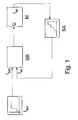
- In der
Figur 1 ist eine schematische Darstellung der Reglerstruktur gezeigt. Dabei wird an der Maschine, beispielhaft ein Elektromotor M, der Stromistwert I_Ist erfasst. Diese Erfassung erfolgt zeitdiskret, also zu jedem Zeitschritt des zeitdiskreten Reglers einmal. - Da der Strom der Maschine eine mehrdimensionale Größe ist, wenn die Maschine eine dreiphasige Versorgung aufweist, ist der Strom als Vektor darzustellen.
- Dieser Vektor ist in einem Koordinatensystem darstellbar, wie Flusskoordinatensystem, Rotorkoordinatensystem oder dergleichen.
- Der Stromistwert I_IST der Figuren ist dabei als Stromkomponente in diesem Koordinatensystem zu verstehen.
- Bei mehreren Stromkomponenten ist für jede dieser Stromkomponenten eine Regelstruktur gemäß der Figuren anwendbar. Insbesondere ist sie jedoch auf jeden Fall auf die drehmomentbildende Stromkomponente als I_IST anwendbar.
- Der Sollwert I_Soll und der Istwert I_IST werden dem Stromregler zugeführt, welcher die Stellgröße entsprechend der Regelabweichung verändert. Im vorliegenden Fall ist vorzugsweise die Spannung die genannte Stellgröße.
-
Figur 2 zeigt den Verlauf des Sollwertes, wobei ein Sprung vorgesehen ist. Dabei wird die Stellgrenze des Reglers erreicht. Somit sind mehrere Zeitschritte des zeitdiskreten Reglers notwendig bis die Nachführung des Istwertes abgeschlossen ist. Hierbei erfolgt die Nachführung schnellstmöglich. - Dabei wurde vorausgesetzt, dass die Regelstrecke, umfassend die Maschine M, ein lineares und integrierendes Verhalten besitzt, wie beispielsweise eine stromunabhängige Induktivität.
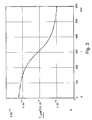
- Wenn jedoch die Induktivität stromabhängig ist in der in
Figur 3 dargestellten Form, ergeben sich die Verläufe nachFigur 4 . - In
Figur 3 nimmt der Wert der Induktivität nach Überschreiten der Sättigungsgrenze auf weniger als ein Drittel ab. - In
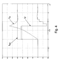
Figur 4 ist der Sollwertverlauf I_Soll entsprechend derFigur 2 ausgeführt. Da wiederum die Stellgrenze für die Spannung als Stellwert überschritten wird, benötigt der Istwert des Stromes wiederum einige Zeitschritte der zeitdiskreten Regelung bis zum Erreichen des stationären Wertes. Allerdings tritt dabei ein Überschwingen auf, das die Stromgrenze des den Motor versorgenden Umrichters überschreiten kann. Dies kann dann zu einem Fehler und einer entsprechenden automatischen Abschaltung des Umrichters führen. - Bei dem erfindungsgemäßen Ausführungsbeispiel wird gemäß
Figur 5 der mittels der zeitdiskreten Stromabtastung Strom erfasst, die Stromkomponente des Stromvektors bestimmt und einem nichtlinearen Übertragungsglied zugeführt. Der Sollwert I_Soll wird ebenfalls einem identischen nichtlinearen Übertragungsglied zugeführt. - Der Regler stellt dann abhängig von der Regelabweichung die Spannung des Motors.
- Als nichtlineares Übertragungsglied wird

verwendet, wobei I der Eingangswert des Gliedes ist, also I_Soll beziehungsweise I_Ist und Ldiff (i) die Stromabhängigkeit der Induktivität des Motors beschreibt. - Somit ist für die Stromkomponente, insbesondere die drehmomentbildende, ein skalarer Regler vorgesehen, der ohne großen Rechenaufwand realisierbar ist und somit als zeitlich schneller Algorithmus realisierbar ist.
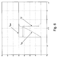
- In
Figur 6 ist wiederum der Sollwertverlauf I_Soll entsprechend derFigur 2 ausgeführt, wobei der Regler nachFigur 5 verwendet ist und eine Stromabhängigkeit der Induktivität gemäβFigur 3 berücksichtigt ist. Da wiederum die Stellgrenze für die Spannung als Stellwert überschritten wird, benötigt der Istwert des Stromes wiederum einige Zeischritte der zeitdiskreten Regelung bis zum Erreichen des stationären Wertes. Es tritt kein Überschwingen auf, wobei der stationäre Wert trotzdem in sehr kurzer Zeit erreicht ist. - Besonders vorteilig ist diese Regelung anwendbar bei synchronmotoren, welche einen hohen Ausnutzungsgrad aufweisen und daher ein stark sättigendes Verhalten haben. Aber auch bei anderen Motoren ist die Erfindung anwendbar.
- Bei weiteren erfindungsgemäßen Ausführungsbeispielen ist als Stellgröße für Spannung zumindest der Betrag des Spannungsvektors der Versorgung des Motors M verwendbar. Alternativ ist aber auch der gesamte Spannungsvektor als Stellgröße verwendbar.
- Als Stromkomponente ist insbesondere die drehmomentbildende vorsehbar.
Claims (8)
- Antrieb, umfassend einen Elektromotor, der von einem Umrichter gespeist ist,
wobei der Umrichter eine zeitdiskrete Regelstruktur umfasst, die den Statorstrom des Elektromotors mittels Stellen der am Motor anliegenden Spannung regelt,
wobei der Strom des Motors zeitdiskret erfasst wird,
wobei die Regelstruklur einen ersten Regler umfasst, dessen Sollwert Ausgangswert eines ersten nichtlinearen Übertragungsgliedes
und dessen Istwert Ausgangswert eines zweiten nichtlinearen Übertragungsgliedes ist,
wobei der Eingangswert des ersten nichtlinearen Obertragungsgliedes der Sollwert einer ersten Stromkomponente des Stromes ist,
wobei der Eingangswert des zweiten nichtlinearen Übertragungsgliedes der Istwert einer ersten Stromkomponente des Stromes ist,- wobei ein nichtlineares Übertragungsglied einer Übertragungsfunktion entspricht, die ein Funktional der stromabhängigen Induktivität des Motors ist- oder wobei ein nichtlineares Übertragungsglied einer Magnetisierungskennlinie des Motors entspricht - Antrieb nach mindestens einem der vorangegangenen Ansprüche,
dadurch gekennzeichnet, dass
das erste und zweite nichtlineare Übertragungsglied gleichartig sind. - Antrieb nach mindestens einem der vorangegangenen Ansprüche,
dadurch gekennzeichnet, dass
das Funktional von der Form
ist, wobei I die Eingangsgröße des Übertragungsgliedes ist. - Antrieb nach mindestens einem der vorangegangenen Ansprüche,
dadurch gekennzeichnet, dass
das Funktional ein Integral der stromabhängigen Induktivität des Motors ist. - Antrieb nach mindestens einem der vorangegangenen Ansprüche,
dadurch gekennzeichnet, dass
der Regler ein linearer Regler, wie P-Regler, ein PI-Regler oder ein PID-Regler, ist, insbesondere mit Vorsteuerung. - Antrieb nach mindestens einem der vorangegangenen Ansprüche,
dadurch gekennzeichnet, dass
aus dem erfassten Strom die Stromkomponenten in einem Koordinatensystem bestimmt werden. - Antrieb nach mindestens einem der vorangegangenen Ansprüche,
dadurch gekennzeichnet, dass
der Umrichter für jede Stromkomponente eine Regelstruktur umfasst, die der Regelstruktur für die erste Stromkomponente gleicht. - Verfahren zur Regelung des Motorstromes bei einem von einem Umrichter gespeisten Elektromotor,
wobei das Verfahren zeitdiskret ausgeführt wird und der Statorstrom des Motors zeitdiskret erfasst wird,
wobei der Statorstrom des Elektromotors geregelt wird,
wobei der Sollwert einer ersten Stromkomponente Eingangswert eines ersten nichtlinearen Übertragungsgliedes ist, dessen Ausgangswert einem Regler als Sollwert zugeführt wird,
wobei der Istwert einer ersten Stromkomponente Eingangswert eines zweiten nichtlinearen Übertragungsgliedes ist, dessen Ausgangswert dem Regler als Istwert zugeführt wird,
wobei die Stellgröße des Reglers die am Motor anliegenden Spannung ist,- wobei ein nichtlineares Übertragungsglied einer Übertragungsfunktion entspricht, die ein Funktional der stromabhängigen Induktivität des Motors ist- oder wobei ein nichtlineares Übertragungsglied einer Magnetisierungskennlinie des Motors entspricht.
Applications Claiming Priority (2)
| Application Number | Priority Date | Filing Date | Title |
|---|---|---|---|
| DE102006035891A DE102006035891B4 (de) | 2006-07-31 | 2006-07-31 | Antrieb, umfassend einen Elektromotor, der von einem Umrichter gespeist ist, und Verfahren zur Regelung des Motorstromes bei einem von einem Umrichter gespeisten Elektromotor |
| PCT/EP2007/005813 WO2008014855A1 (de) | 2006-07-31 | 2007-06-30 | Antrieb und verfahren |
Publications (2)
| Publication Number | Publication Date |
|---|---|
| EP2050186A1 EP2050186A1 (de) | 2009-04-22 |
| EP2050186B1 true EP2050186B1 (de) | 2011-12-21 |
Family
ID=38779745
Family Applications (1)
| Application Number | Title | Priority Date | Filing Date |
|---|---|---|---|
| EP07764973A Active EP2050186B1 (de) | 2006-07-31 | 2007-06-30 | Antrieb und verfahren |
Country Status (8)
| Country | Link |
|---|---|
| US (1) | US9948225B2 (de) |
| EP (1) | EP2050186B1 (de) |
| JP (1) | JP5350239B2 (de) |
| CN (1) | CN101496274B (de) |
| AT (1) | ATE538530T1 (de) |
| DE (1) | DE102006035891B4 (de) |
| DK (1) | DK2050186T3 (de) |
| WO (1) | WO2008014855A1 (de) |
Families Citing this family (2)
| Publication number | Priority date | Publication date | Assignee | Title |
|---|---|---|---|---|
| DE102017006629A1 (de) * | 2016-08-22 | 2018-02-22 | Sew-Eurodrive Gmbh & Co Kg | Verfahren zum Betreiben eines Systems mit mechanisch miteinander gekopelten Antrieben und übergeordnetem Rechner und System |
| CN112019119B (zh) * | 2020-08-31 | 2021-09-07 | 合肥工业大学 | 可调阻尼的永磁同步电机离散域电流环控制方法 |
Family Cites Families (36)
| Publication number | Priority date | Publication date | Assignee | Title |
|---|---|---|---|---|
| DE199752C (de) | ||||
| DE1941312B2 (de) * | 1969-08-14 | 1972-11-23 | Siemens AG, 1000 Berlin u. 8000 München | Verfahren und einrichtung zur steuerung von asynchronmaschinen |
| DE2340506B2 (de) | 1973-08-10 | 1979-02-08 | Brown, Boveri & Cie Ag, 6800 Mannheim | Adaptiver Stromregler |
| DE2721459C2 (de) | 1977-05-12 | 1979-02-22 | Siemens Ag, 1000 Berlin Und 8000 Muenchen | Schaltungsanordnung zum Regeln des Erregerstroms einer elektrischen Maschine, insbesondere einer Gleichstrommaschine |
| DE3149402A1 (de) | 1980-11-26 | 1983-06-16 | Licentia Patent-Verwaltungs-Gmbh, 6000 Frankfurt | Synchronmaschinenfuehrung ueber ein aufgeteiltes maschinenmodell |
| DE3438504A1 (de) * | 1984-10-20 | 1986-04-24 | Brown, Boveri & Cie Ag, 6800 Mannheim | Verfahren und einrichtung zur regelung einer drehfeldmaschine |
| DE4115338A1 (de) * | 1991-05-10 | 1992-11-12 | Bosch Gmbh Robert | Verfahren zum sensorlosen erfassen und/oder regeln einer elektrischen maschine |
| JP2755011B2 (ja) * | 1992-02-13 | 1998-05-20 | 三菱電機株式会社 | モータ駆動制御装置 |
| JPH06195104A (ja) | 1992-12-24 | 1994-07-15 | Hitachi Ltd | プロセス制御方法 |
| DE4306350C1 (de) * | 1993-02-23 | 1994-04-21 | Licentia Gmbh | Stromregler |
| FI97654C (fi) | 1994-09-09 | 1997-01-27 | Abb Industry Oy | Menetelmä epätahtikoneen käynnistämiseksi |
| US6025691A (en) * | 1995-05-29 | 2000-02-15 | Toyota Jidosha Kabushiki Kaisha | Synchronous motor control system and method of controlling synchronous motor |
| JPH09238489A (ja) | 1996-03-04 | 1997-09-09 | Olympus Optical Co Ltd | モータ速度制御方法及びモータ速度制御装置 |
| DE59601892D1 (de) * | 1996-11-04 | 1999-06-17 | Siemens Ag | Feldorientierte Regelung einer Drehfeldmaschine an der Spannungsdecke |
| JPH11150996A (ja) * | 1997-11-13 | 1999-06-02 | Toyota Motor Corp | モータ制御装置 |
| US5929400A (en) * | 1997-12-22 | 1999-07-27 | Otis Elevator Company | Self commissioning controller for field-oriented elevator motor/drive system |
| US7103425B1 (en) * | 1999-01-08 | 2006-09-05 | Lexmark International, Inc. | Method of regulating a target system using a frequency comparison of feedback and reference pulse trains |
| DE19919752C5 (de) | 1999-04-29 | 2010-12-16 | Sew-Eurodrive Gmbh & Co. Kg | Verfahren zum Zuschalten eines Umrichters an einen Asynchronmotor |
| JP3520002B2 (ja) * | 1999-12-08 | 2004-04-19 | 三菱電機株式会社 | 誘導電動機のベクトル制御装置 |
| JP4411796B2 (ja) * | 2001-04-27 | 2010-02-10 | 富士電機システムズ株式会社 | 速度センサを持たない誘導モータドライブの制御システム、オブザーバ及び制御方法 |
| US6469916B1 (en) * | 2001-10-01 | 2002-10-22 | Rockwell Automation Technologies, Inc. | Method and apparatus for compensating for device dynamics and voltage drop in inverter based control systems |
| US6586914B2 (en) * | 2001-11-19 | 2003-07-01 | General Electric Company | Wound field synchronous machine control system and method |
| US6630809B2 (en) * | 2001-11-29 | 2003-10-07 | Ballard Power Systems Corporation | System and method for induction motor control |
| JP3855157B2 (ja) | 2002-03-05 | 2006-12-06 | 独立行政法人科学技術振興機構 | 非線形分離制御方法および装置 |
| DE10228824A1 (de) * | 2002-06-27 | 2004-05-19 | Siemens Ag | Verfahren und Vorrichtung zur Ermittlung eines Durchgehens eines drehzahlgeregelten, permanenterregten Synchronmotors |
| DE10300953B4 (de) | 2003-01-13 | 2006-04-27 | Siemens Ag | Verfahren zum Bremsen eines mittels eines Stromrichter gespeisten Motors |
| US7023190B2 (en) * | 2003-02-10 | 2006-04-04 | Power-One, Inc. | ADC transfer function providing improved dynamic regulation in a switched mode power supply |
| US20050031140A1 (en) * | 2003-08-07 | 2005-02-10 | Tymphany Corporation | Position detection of an actuator using a capacitance measurement |
| US20060104451A1 (en) * | 2003-08-07 | 2006-05-18 | Tymphany Corporation | Audio reproduction system |
| KR100608656B1 (ko) * | 2003-09-20 | 2006-08-04 | 엘지전자 주식회사 | 모터의 속도제어장치 |
| DE10361430B4 (de) | 2003-12-23 | 2005-12-01 | Sew-Eurodrive Gmbh & Co. Kg | Umrichter |
| KR100634588B1 (ko) * | 2003-12-30 | 2006-10-13 | 현대자동차주식회사 | 영구자석 동기모터 제어시스템 및 제어방법 |
| JP2006238631A (ja) * | 2005-02-25 | 2006-09-07 | Mitsubishi Heavy Ind Ltd | Id/Iqテーブルを使用したモータの制御方法 |
| FR2884658B1 (fr) * | 2005-04-13 | 2007-05-18 | Schneider Toshiba Inverter | Procede d'ajustement de parametres d'un moteur electrique et variateur de vitesse utilisant un tel procede |
| US7187152B1 (en) * | 2005-10-14 | 2007-03-06 | Delta Electronic Inc. | AC servo drive without current sensor |
| EP1777806A2 (de) * | 2005-10-21 | 2007-04-25 | NSK Ltd. | Steuervorrichtung des elektrischen Antriebs und elektrische Servolenkung |
-
2006
- 2006-07-31 DE DE102006035891A patent/DE102006035891B4/de active Active
-
2007
- 2007-06-30 JP JP2009522119A patent/JP5350239B2/ja active Active
- 2007-06-30 CN CN2007800278231A patent/CN101496274B/zh active Active
- 2007-06-30 WO PCT/EP2007/005813 patent/WO2008014855A1/de active Application Filing
- 2007-06-30 US US12/376,116 patent/US9948225B2/en active Active
- 2007-06-30 AT AT07764973T patent/ATE538530T1/de active
- 2007-06-30 DK DK07764973.9T patent/DK2050186T3/da active
- 2007-06-30 EP EP07764973A patent/EP2050186B1/de active Active
Also Published As
| Publication number | Publication date |
|---|---|
| CN101496274B (zh) | 2011-09-07 |
| CN101496274A (zh) | 2009-07-29 |
| JP5350239B2 (ja) | 2013-11-27 |
| ATE538530T1 (de) | 2012-01-15 |
| US9948225B2 (en) | 2018-04-17 |
| WO2008014855A1 (de) | 2008-02-07 |
| DK2050186T3 (da) | 2012-01-30 |
| DE102006035891A1 (de) | 2008-02-07 |
| DE102006035891B4 (de) | 2009-04-16 |
| JP2009545937A (ja) | 2009-12-24 |
| US20090322263A1 (en) | 2009-12-31 |
| EP2050186A1 (de) | 2009-04-22 |
Similar Documents
| Publication | Publication Date | Title |
|---|---|---|
| DE102011009935B4 (de) | Verfahren zum Ansteuern eines optimalen Betriebspunktes bei einer Synchronmaschine und eine umrichtergespeiste Synchronmaschine | |
| DE102008013799B4 (de) | Verfahren und System zur Steuerung von Permanentmagnet-AC-Maschinen | |
| DE102009024138B4 (de) | Verfahren zur Regelung der Temperatur einer Glühkerze | |
| DE102015223365A1 (de) | Verfahren zur Ermittlung eines d- und q-Stromes zur Ansteuerung einer permanenterregten Synchronmaschine | |
| DE102012205371A1 (de) | Reglerstruktur und Verfahren zur feldorientierten Regelung einer Drehfeldmaschine bei Feldschwächung | |
| EP3593448B1 (de) | Regelvorrichtung für eine elektrische maschine, elektrisches antriebssystem und verfahren zur regelung einer elektrischen maschine | |
| EP2050186B1 (de) | Antrieb und verfahren | |
| EP2619900B1 (de) | Verfahren zur (kupfer-)verlustoptimalen regelung einer asynchronmaschine mit einem umrichter | |
| DE102007027827B4 (de) | Antrieb und Verfahren | |
| DE102010021488A1 (de) | Verfahren zur (kupfer-)verlustoptimalen Regelung einer Asynchronmaschine mit einem Frequenzumrichter | |
| EP2199879A1 (de) | Vorrichtung und Verfahren zur Minimierung eines dynamischen Schleppfehlers | |
| WO2022122262A1 (de) | ELEKTRISCHES SYSTEM UND VERFAHREN UND VORRICHTUNG ZUM BESTIMMEN EINES WERTEVERLAUFS EINER STEUERGRÖßE | |
| DE102014215479A1 (de) | Verfahren zum Betreiben einer geschalteten Reluktanzmaschine | |
| EP3152829B1 (de) | Verfahren und vorrichtung zur steuerung eines betriebs eines elektromotors | |
| DE102012018819A1 (de) | Verfahren zum Betreiben eines Umrichters zur Speisung einer Elektromaschine und Elektromaschine | |
| EP3878089B1 (de) | Verfahren und vorrichtung zur stellwertbegrenzung für die feldorientierte stromregelung | |
| WO2018162335A1 (de) | Verfahren zur regelung einer elektrischen maschine, regelvorrichtung für eine elektrische maschine und elektrisches antriebssystem | |
| DE102021203591A1 (de) | Verfahren zur feldorientierten Regelung eines Elektromotors | |
| EP4342070A1 (de) | SPRITZGIEßMASCHINE MIT ELEKTRISCHEN SCHALTEINHEITEN UND VERFAHREN ZUM SYNCHRONISIEREN VON STRÖMEN VON ELEKTRISCHEN SCHALTEINHEITEN | |
| EP2132606B1 (de) | Verfahren zum regeln einer position und antrieb | |
| DE102018133058A1 (de) | Verfahren zum steuern eines automatisierungsprozesses in echtzeit | |
| DE102004030974A1 (de) | Verfahren und Vorrichtung zur Reduzierung der Momentwelligkeit eines Drehmoments einer direkt geregelten elektrischen Drehfeldmaschine | |
| DE102015114750A1 (de) | Verfahren zur Steuerung einer elektrischen Maschine, Computerprogramm, Reglereinrichtung sowie elektrische Maschine |
Legal Events
| Date | Code | Title | Description |
|---|---|---|---|
| PUAI | Public reference made under article 153(3) epc to a published international application that has entered the european phase |
Free format text: ORIGINAL CODE: 0009012 |
|
| 17P | Request for examination filed |
Effective date: 20090302 |
|
| AK | Designated contracting states |
Kind code of ref document: A1 Designated state(s): AT BE BG CH CY CZ DE DK EE ES FI FR GB GR HU IE IS IT LI LT LU LV MC MT NL PL PT RO SE SI SK TR |
|
| AX | Request for extension of the european patent |
Extension state: AL BA HR MK RS |
|
| 17Q | First examination report despatched |
Effective date: 20110406 |
|
| GRAP | Despatch of communication of intention to grant a patent |
Free format text: ORIGINAL CODE: EPIDOSNIGR1 |
|
| GRAS | Grant fee paid |
Free format text: ORIGINAL CODE: EPIDOSNIGR3 |
|
| GRAA | (expected) grant |
Free format text: ORIGINAL CODE: 0009210 |
|
| AK | Designated contracting states |
Kind code of ref document: B1 Designated state(s): AT BE BG CH CY CZ DE DK EE ES FI FR GB GR HU IE IS IT LI LT LU LV MC MT NL PL PT RO SE SI SK TR |
|
| DAX | Request for extension of the european patent (deleted) | ||
| REG | Reference to a national code |
Ref country code: GB Ref legal event code: FG4D Free format text: NOT ENGLISH |
|
| REG | Reference to a national code |
Ref country code: CH Ref legal event code: EP Ref country code: CH Ref legal event code: NV Representative=s name: HEPP WENGER RYFFEL AG |
|
| REG | Reference to a national code |
Ref country code: AT Ref legal event code: REF Ref document number: 538530 Country of ref document: AT Kind code of ref document: T Effective date: 20120115 |
|
| REG | Reference to a national code |
Ref country code: IE Ref legal event code: FG4D |
|
| REG | Reference to a national code |
Ref country code: DK Ref legal event code: T3 |
|
| REG | Reference to a national code |
Ref country code: DE Ref legal event code: R096 Ref document number: 502007008917 Country of ref document: DE Effective date: 20120308 |
|
| REG | Reference to a national code |
Ref country code: NL Ref legal event code: VDEP Effective date: 20111221 |
|
| PG25 | Lapsed in a contracting state [announced via postgrant information from national office to epo] |
Ref country code: LT Free format text: LAPSE BECAUSE OF FAILURE TO SUBMIT A TRANSLATION OF THE DESCRIPTION OR TO PAY THE FEE WITHIN THE PRESCRIBED TIME-LIMIT Effective date: 20111221 |
|
| LTIE | Lt: invalidation of european patent or patent extension |
Effective date: 20111221 |
|
| PG25 | Lapsed in a contracting state [announced via postgrant information from national office to epo] |
Ref country code: LV Free format text: LAPSE BECAUSE OF FAILURE TO SUBMIT A TRANSLATION OF THE DESCRIPTION OR TO PAY THE FEE WITHIN THE PRESCRIBED TIME-LIMIT Effective date: 20111221 Ref country code: SI Free format text: LAPSE BECAUSE OF FAILURE TO SUBMIT A TRANSLATION OF THE DESCRIPTION OR TO PAY THE FEE WITHIN THE PRESCRIBED TIME-LIMIT Effective date: 20111221 Ref country code: NL Free format text: LAPSE BECAUSE OF FAILURE TO SUBMIT A TRANSLATION OF THE DESCRIPTION OR TO PAY THE FEE WITHIN THE PRESCRIBED TIME-LIMIT Effective date: 20111221 Ref country code: GR Free format text: LAPSE BECAUSE OF FAILURE TO SUBMIT A TRANSLATION OF THE DESCRIPTION OR TO PAY THE FEE WITHIN THE PRESCRIBED TIME-LIMIT Effective date: 20120322 Ref country code: SE Free format text: LAPSE BECAUSE OF FAILURE TO SUBMIT A TRANSLATION OF THE DESCRIPTION OR TO PAY THE FEE WITHIN THE PRESCRIBED TIME-LIMIT Effective date: 20111221 |
|
| PG25 | Lapsed in a contracting state [announced via postgrant information from national office to epo] |
Ref country code: CY Free format text: LAPSE BECAUSE OF FAILURE TO SUBMIT A TRANSLATION OF THE DESCRIPTION OR TO PAY THE FEE WITHIN THE PRESCRIBED TIME-LIMIT Effective date: 20111221 |
|
| REG | Reference to a national code |
Ref country code: IE Ref legal event code: FD4D |
|
| PG25 | Lapsed in a contracting state [announced via postgrant information from national office to epo] |
Ref country code: SK Free format text: LAPSE BECAUSE OF FAILURE TO SUBMIT A TRANSLATION OF THE DESCRIPTION OR TO PAY THE FEE WITHIN THE PRESCRIBED TIME-LIMIT Effective date: 20111221 Ref country code: EE Free format text: LAPSE BECAUSE OF FAILURE TO SUBMIT A TRANSLATION OF THE DESCRIPTION OR TO PAY THE FEE WITHIN THE PRESCRIBED TIME-LIMIT Effective date: 20111221 Ref country code: IE Free format text: LAPSE BECAUSE OF FAILURE TO SUBMIT A TRANSLATION OF THE DESCRIPTION OR TO PAY THE FEE WITHIN THE PRESCRIBED TIME-LIMIT Effective date: 20111221 Ref country code: BG Free format text: LAPSE BECAUSE OF FAILURE TO SUBMIT A TRANSLATION OF THE DESCRIPTION OR TO PAY THE FEE WITHIN THE PRESCRIBED TIME-LIMIT Effective date: 20120321 Ref country code: IS Free format text: LAPSE BECAUSE OF FAILURE TO SUBMIT A TRANSLATION OF THE DESCRIPTION OR TO PAY THE FEE WITHIN THE PRESCRIBED TIME-LIMIT Effective date: 20120421 Ref country code: CZ Free format text: LAPSE BECAUSE OF FAILURE TO SUBMIT A TRANSLATION OF THE DESCRIPTION OR TO PAY THE FEE WITHIN THE PRESCRIBED TIME-LIMIT Effective date: 20111221 |
|
| PG25 | Lapsed in a contracting state [announced via postgrant information from national office to epo] |
Ref country code: PL Free format text: LAPSE BECAUSE OF FAILURE TO SUBMIT A TRANSLATION OF THE DESCRIPTION OR TO PAY THE FEE WITHIN THE PRESCRIBED TIME-LIMIT Effective date: 20111221 Ref country code: PT Free format text: LAPSE BECAUSE OF FAILURE TO SUBMIT A TRANSLATION OF THE DESCRIPTION OR TO PAY THE FEE WITHIN THE PRESCRIBED TIME-LIMIT Effective date: 20120423 Ref country code: RO Free format text: LAPSE BECAUSE OF FAILURE TO SUBMIT A TRANSLATION OF THE DESCRIPTION OR TO PAY THE FEE WITHIN THE PRESCRIBED TIME-LIMIT Effective date: 20111221 |
|
| PLBE | No opposition filed within time limit |
Free format text: ORIGINAL CODE: 0009261 |
|
| STAA | Information on the status of an ep patent application or granted ep patent |
Free format text: STATUS: NO OPPOSITION FILED WITHIN TIME LIMIT |
|
| 26N | No opposition filed |
Effective date: 20120924 |
|
| BERE | Be: lapsed |
Owner name: SEW-EURODRIVE G.M.B.H. & CO. KG Effective date: 20120630 |
|
| REG | Reference to a national code |
Ref country code: DE Ref legal event code: R097 Ref document number: 502007008917 Country of ref document: DE Effective date: 20120924 |
|
| PG25 | Lapsed in a contracting state [announced via postgrant information from national office to epo] |
Ref country code: MC Free format text: LAPSE BECAUSE OF NON-PAYMENT OF DUE FEES Effective date: 20120630 |
|
| PG25 | Lapsed in a contracting state [announced via postgrant information from national office to epo] |
Ref country code: BE Free format text: LAPSE BECAUSE OF NON-PAYMENT OF DUE FEES Effective date: 20120630 Ref country code: ES Free format text: LAPSE BECAUSE OF FAILURE TO SUBMIT A TRANSLATION OF THE DESCRIPTION OR TO PAY THE FEE WITHIN THE PRESCRIBED TIME-LIMIT Effective date: 20120401 |
|
| PG25 | Lapsed in a contracting state [announced via postgrant information from national office to epo] |
Ref country code: MT Free format text: LAPSE BECAUSE OF FAILURE TO SUBMIT A TRANSLATION OF THE DESCRIPTION OR TO PAY THE FEE WITHIN THE PRESCRIBED TIME-LIMIT Effective date: 20111221 |
|
| PG25 | Lapsed in a contracting state [announced via postgrant information from national office to epo] |
Ref country code: TR Free format text: LAPSE BECAUSE OF FAILURE TO SUBMIT A TRANSLATION OF THE DESCRIPTION OR TO PAY THE FEE WITHIN THE PRESCRIBED TIME-LIMIT Effective date: 20111221 |
|
| PG25 | Lapsed in a contracting state [announced via postgrant information from national office to epo] |
Ref country code: LU Free format text: LAPSE BECAUSE OF NON-PAYMENT OF DUE FEES Effective date: 20120630 |
|
| PG25 | Lapsed in a contracting state [announced via postgrant information from national office to epo] |
Ref country code: HU Free format text: LAPSE BECAUSE OF FAILURE TO SUBMIT A TRANSLATION OF THE DESCRIPTION OR TO PAY THE FEE WITHIN THE PRESCRIBED TIME-LIMIT Effective date: 20070630 |
|
| REG | Reference to a national code |
Ref country code: FR Ref legal event code: PLFP Year of fee payment: 10 |
|
| REG | Reference to a national code |
Ref country code: FR Ref legal event code: PLFP Year of fee payment: 11 |
|
| REG | Reference to a national code |
Ref country code: FR Ref legal event code: PLFP Year of fee payment: 12 |
|
| PGFP | Annual fee paid to national office [announced via postgrant information from national office to epo] |
Ref country code: IT Payment date: 20230510 Year of fee payment: 17 Ref country code: FR Payment date: 20230510 Year of fee payment: 17 Ref country code: DK Payment date: 20230613 Year of fee payment: 17 Ref country code: DE Payment date: 20230630 Year of fee payment: 17 |
|
| PGFP | Annual fee paid to national office [announced via postgrant information from national office to epo] |
Ref country code: FI Payment date: 20230615 Year of fee payment: 17 Ref country code: AT Payment date: 20230609 Year of fee payment: 17 |
|
| PGFP | Annual fee paid to national office [announced via postgrant information from national office to epo] |
Ref country code: GB Payment date: 20230511 Year of fee payment: 17 Ref country code: CH Payment date: 20230905 Year of fee payment: 17 |