EP2048046B1 - Fahrzeugsteuersystem - Google Patents
Fahrzeugsteuersystem Download PDFInfo
- Publication number
- EP2048046B1 EP2048046B1 EP20070791825 EP07791825A EP2048046B1 EP 2048046 B1 EP2048046 B1 EP 2048046B1 EP 20070791825 EP20070791825 EP 20070791825 EP 07791825 A EP07791825 A EP 07791825A EP 2048046 B1 EP2048046 B1 EP 2048046B1
- Authority
- EP
- European Patent Office
- Prior art keywords
- vehicle
- mobile terminal
- behavioral pattern
- pattern information
- current location
- Prior art date
- Legal status (The legal status is an assumption and is not a legal conclusion. Google has not performed a legal analysis and makes no representation as to the accuracy of the status listed.)
- Active
Links
Images
Classifications
-
- B—PERFORMING OPERATIONS; TRANSPORTING
- B60—VEHICLES IN GENERAL
- B60R—VEHICLES, VEHICLE FITTINGS, OR VEHICLE PARTS, NOT OTHERWISE PROVIDED FOR
- B60R25/00—Fittings or systems for preventing or indicating unauthorised use or theft of vehicles
- B60R25/10—Fittings or systems for preventing or indicating unauthorised use or theft of vehicles actuating a signalling device
-
- B—PERFORMING OPERATIONS; TRANSPORTING
- B60—VEHICLES IN GENERAL
- B60R—VEHICLES, VEHICLE FITTINGS, OR VEHICLE PARTS, NOT OTHERWISE PROVIDED FOR
- B60R25/00—Fittings or systems for preventing or indicating unauthorised use or theft of vehicles
- B60R25/01—Fittings or systems for preventing or indicating unauthorised use or theft of vehicles operating on vehicle systems or fittings, e.g. on doors, seats or windscreens
- B60R25/04—Fittings or systems for preventing or indicating unauthorised use or theft of vehicles operating on vehicle systems or fittings, e.g. on doors, seats or windscreens operating on the propulsion system, e.g. engine or drive motor
-
- B—PERFORMING OPERATIONS; TRANSPORTING
- B60—VEHICLES IN GENERAL
- B60R—VEHICLES, VEHICLE FITTINGS, OR VEHICLE PARTS, NOT OTHERWISE PROVIDED FOR
- B60R25/00—Fittings or systems for preventing or indicating unauthorised use or theft of vehicles
- B60R25/10—Fittings or systems for preventing or indicating unauthorised use or theft of vehicles actuating a signalling device
- B60R25/1004—Alarm systems characterised by the type of sensor, e.g. current sensing means
-
- B—PERFORMING OPERATIONS; TRANSPORTING
- B60—VEHICLES IN GENERAL
- B60R—VEHICLES, VEHICLE FITTINGS, OR VEHICLE PARTS, NOT OTHERWISE PROVIDED FOR
- B60R25/00—Fittings or systems for preventing or indicating unauthorised use or theft of vehicles
- B60R25/30—Detection related to theft or to other events relevant to anti-theft systems
- B60R25/305—Detection related to theft or to other events relevant to anti-theft systems using a camera
-
- B—PERFORMING OPERATIONS; TRANSPORTING
- B60—VEHICLES IN GENERAL
- B60R—VEHICLES, VEHICLE FITTINGS, OR VEHICLE PARTS, NOT OTHERWISE PROVIDED FOR
- B60R25/00—Fittings or systems for preventing or indicating unauthorised use or theft of vehicles
- B60R25/30—Detection related to theft or to other events relevant to anti-theft systems
- B60R25/33—Detection related to theft or to other events relevant to anti-theft systems of global position, e.g. by providing GPS coordinates
-
- H—ELECTRICITY
- H04—ELECTRIC COMMUNICATION TECHNIQUE
- H04L—TRANSMISSION OF DIGITAL INFORMATION, e.g. TELEGRAPHIC COMMUNICATION
- H04L12/00—Data switching networks
- H04L12/66—Arrangements for connecting between networks having differing types of switching systems, e.g. gateways
-
- H—ELECTRICITY
- H04—ELECTRIC COMMUNICATION TECHNIQUE
- H04L—TRANSMISSION OF DIGITAL INFORMATION, e.g. TELEGRAPHIC COMMUNICATION
- H04L12/00—Data switching networks
- H04L12/28—Data switching networks characterised by path configuration, e.g. LAN [Local Area Networks] or WAN [Wide Area Networks]
- H04L12/40—Bus networks
- H04L2012/40267—Bus for use in transportation systems
- H04L2012/40273—Bus for use in transportation systems the transportation system being a vehicle
Definitions
- the present invention relates to a vehicle control system that controls vehicle apparatuses installed in a vehicle, in accordance with a positional relationship between a current location of a mobile terminal and a current location of the vehicle.
- Document DE 19826904 shows a system according to the preamble of claim 1.
- the predetermined instructions are inflexibly determined in accordance with the distance and the positional relationship between the mobile communications apparatus and the vehicle. Therefore, instructions may be made in contradiction to a behavioral pattern of the user.
- the present invention has been made in order to eliminate the above problem, and the objective of the present invention is to appropriately control the vehicle apparatuses installed in the vehicle.
- one embodiment of the present invention provides a vehicle control system that includes a mobile terminal that transmits a current location of the mobile terminal, a receiving portion that is installed in a vehicle and receives the current location transmitted from the mobile terminal, a vehicle location detecting portion that detects a current location of the vehicle, a controlling portion that controls a vehicle apparatus installed in the vehicle in accordance with a positional relationship between the current position of the mobile terminal received by the receiving portion and the current location of the vehicle detected by the vehicle location detecting portion, and a memory portion that automatically creates and stores behavioral pattern information of a user of the vehicle.
- the controlling portion controls the vehicle apparatus in accordance with the behavioral pattern information stored in the memory portion and the positional relationship between the current location of the mobile terminal and the current location of the vehicle.
- the controlling portion controls the vehicle apparatus in accordance with the behavioral pattern stored in the storing portion and the positional relationship between the current location of the mobile terminal and the current location of the vehicle.
- the vehicle apparatus can be appropriately controlled in consideration of the behavioral pattern of the user and the positional relationship between the vehicle and the user carrying the mobile terminal.
- the behavioral pattern information stored in the memory portion may include at least one of time when the vehicle is used, a location of the vehicle, and content about operation of the vehicle apparatus.
- the vehicle apparatus can be preferably controlled in accordance with the time when the vehicle is used by the user, the location of the vehicle, or the content about the operation of the vehicle apparatus.
- an in-vehicle transceiver may be turned to the off-standby state (turned off) outside of the time when the vehicle is being used, thereby reducing standby electricity consumption.
- the behavioral pattern information may be obtained by associating time when the vehicle is used, a location of the vehicle, and content about operation of the vehicle apparatus with one another.
- the receiving portion and the mobile terminal communicate via an information center, where the memory portion is arranged in one of the vehicle, the mobile terminal, and the information center, and where the behavioral pattern information stored in the memory portion may be subjected to one of registration, alteration, and deletion via one of the mobile terminal, the information center, and an input/output apparatus arranged in the vehicle.
- the behavioral pattern information is kept reliable and updated, since the user can carry out at least one of registration, alteration, and deletion of the behavioral pattern information in any location and at any time (e.g., immediately).
- the receiving portion and the mobile terminal communicate via an information center, where the memory portion is arranged in the vehicle, and where the behavioral pattern information stored in the memory portion may be subjected to one of registration, alteration, and deletion only via the input/output apparatus arranged in the vehicle.
- communications cost can be reduced for the communications between the receiving portion and the information center when the behavioral pattern information is registered, deleted, or altered.
- access to the behavior database from outside is restricted, the information in the behavior database is kept highly confidential.
- the controlling portion may include a behavior estimation portion that estimates the content about the operation of the vehicle apparatus in accordance with the behavioral pattern information stored in the memory portion, and the content about the operation of the vehicle apparatus, the content being estimated by the behavior estimation portion, may be performed when the distance between the current location of the mobile terminal and the current location of the vehicle is less than a predetermined distance.
- the content about the operation of the vehicle apparatus estimated in accordance with the behavioral pattern of the user can be automatically carried out depending on the distance between the user and the vehicle.
- the behavioral pattern information may further include a time period of nonuse when the vehicle is not being used by the user, and the controlling portion may prevent the content about the operation of the vehicle apparatus from being performed during the time period of nonuse. With this, the vehicle apparatus can be assuredly prevented from malfunctioning during the time period of nonuse.
- the behavioral pattern information may further include a location of nonuse where the vehicle is not used by the user, and the controlling portion may prevent the content about the operation of the vehicle apparatus from being performed when the vehicle is in the location of nonuse. With this, the vehicle apparatus can be assuredly prevented from malfunctioning when the vehicle is in the location of nonuse.
- the vehicle apparatuses installed in a vehicle can be appropriately controlled.
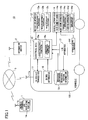
- FIG. 1 is a schematic block diagram of an example of a vehicle control system according to one embodiment of the present invention.
- a vehicle control system 10 includes a mobile terminal 1, an in-vehicle transceiver (receiving portion) 11 that transmits/receives data to/from the mobile terminal 1, a navigation apparatus (vehicle location detecting portion) 12 that detects a current location of a vehicle 100, a behavior database (memory unit) 13 that stores information on a behavioral pattern of a user (e.g., an owner of the vehicle), a control ECU (controlling portion) 15 that controls vehicle apparatuses 14 installed in the vehicle 100, and a clock apparatus 16 that detects a present year, month, date and time.
- the mobile terminal 1 incorporates a Global Positioning System (GPS) receiving portion 1a that detects a current location of the mobile terminal 1.
- the mobile terminal 1 may be any terminal such as a mobile telephone, a portable computer, or the like.
- the GPS receiving portion 1a receives GPS radio waves and computes the current location of the mobile terminal 1.
- the mobile terminal 1 has a display portion made of, for example, a liquid crystal screen that displays various types of information, and plural buttons that enable input operations.
- the in-vehicle transceiver 11 is, for example, a Data Communication Module (DCM) apparatus, an in-vehicle telephone, or the like, installed in the vehicle 100.
- DCM Data Communication Module
- the in-vehicle transceiver 11 transmits/receives data to/from the mobile terminal 1 via antennas 1b, 11a.
- the in-vehicle transceiver 11 serves as a server and is configured to transmit/receive data to/from the mobile terminal 1 via an information center 2 and a communication network 3
- the in-vehicle transceiver 11 may be configured to directly communicate with the mobile terminal 1, not via the information center 2 and the communication network 3.
- the mobile terminal 1 transmits data on the current location of the mobile terminal 1, the current location having been detected by the GPS receiving portion 1a, to the in-vehicle transceiver 11 via the information center 2 and the communications network 3.
- the in-vehicle transceiver 11 is connected to the control ECU 15 and transmits the received data to the control ECU 15.
- the in-vehicle transceiver 11 transmits data received from the control ECU and transmits this received data to the outside such as the information center 2 or the like.
- the navigation apparatus 12 has a GPS receiving portion 12a that receives the GPS radio waves transmitted from plural GPS satellites so as to detect the current location of the vehicle 100, a route setting portion 12b that plans a travel route to a destination, and a map storage portion 12c that stores terrain information.
- the GPS receiving portion 12a may be an independent element.
- the navigation apparatus 12 is connected to the control ECU 15 and transmits data on the current location of the vehicle 100 to the control ECU 15, for example.
- the behavior database 13 is composed of, for example, a hard-disk drive and stores plural behavioral patterns of the user in the form of tables, maps, or the like.
- the behavior database 13 stores as behavioral pattern information, for example, when and how the vehicle 100 is used, location of the vehicle 100, and content about the operation of the vehicle apparatuses 14, all of which are associated with one another.
- a user behavioral pattern is "activating an air conditioner 14a of the vehicle 100 in his/her residence parking lot in a time period of 7 am to 8 am
- content about operation of vehicle apparatuses 14: activating the air conditioner 14a” are stored in association with one anther in the behavior database 13.
- the behavior database 13 stores various arbitrary types of behavioral pattern information.
- the behavioral pattern information may include, "time period of use: 6 am to 7 am, vehicle location: residence parking lot, content about the operation of vehicle apparatuses 14: activating the engine for warming-up” or "time period of use: 8 pm to 9 pm, vehicle location: long-term parking lot, content about the operation of vehicle apparatuses 14: activating a seat heater apparatus 14e".
- the behavioral pattern information may include a time period of nonuse indicating that the vehicle 100 is not expected to be used. For example, when the user does not use the vehicle 100 for an extended period of time due to a business trip in his/her schedule, the period of time is assumed to be the time period of nonuse. (This time period includes year, month, date, and time).
- schedule information may be stored in advance in the mobile terminal 1 of the user and automatically transmitted to the behavior database 13 through wireless communications between the mobile terminal 1 and the in-vehicle transceiver 11 so as to be stored in the behavior database 13.
- the behavioral pattern information may include a location of nonuse indicating a location (e.g., a parking lot at an airport) where the vehicle 100 is not used for a predetermined extended period of time (e.g., 6 hours or more).
- a location of nonuse may be a parking lot at an airport.
- the user tends to go far away and thus the vehicle 100 is expected not to be used for a long time after having been parked.
- the system 100 is configured so that the behavioral pattern information of the user can be newly registered, modified, deleted.
- the behavior database 13 may be connected to an input/output apparatus device 17 having a touch-panel display.
- the user can register new behavioral pattern information in the behavior database 13, and modify, edit, and delete the behavioral pattern information that has already been registered, via the touch-panel display of the input/output apparatus device 17.
- Behavioral pattern information input via the touch-panel display of the input/output apparatus device 17 is stored in the behavior database 13 via the input/output apparatus device 17.
- the user may register new behavioral pattern information in the behavior database 13, and modify, edit, and delete the pre-registered behavioral pattern information via the mobile terminal 1.
- Behavioral pattern information input via the mobile terminal 1 is stored in the behavior database 13 via the mobile terminal 1, the information center 2, and the in-vehicle transceiver 11.
- the user carrying the mobile terminal 1 can register, modify, edit, and delete the behavioral pattern information anywhere and anytime, thereby providing the user with improved convenience.
- the behavioral pattern information becomes reliable and updated.
- the clock apparatus 16 has a calendar function that detects the present year, month, and date (including national holidays), and a clock function that detects the present time. By the way, the clock apparatus 16 may be incorporated in the control ECU 15.
- the control ECU 15 controls the vehicle apparatuses 14 installed in the vehicle 100.
- the vehicle apparatuses 14 may include optional apparatuses for controlling the vehicle, including the air conditioner 14a for air-conditioning the in-vehicle environment, an anticrime (security) apparatus 14b that prevents a third party from entering the vehicle, an engine control apparatus 14c that starts/stops the engine, a locking device 14d that locks/unlocks doors of the vehicle 100, the seat heater apparatus 14e that heats vehicle seats, and the like.
- the in-vehicle transceiver 11 may be included in the vehicle apparatuses 14.
- the air conditioner 14a has cooling and heating functions so as to control the in-vehicle temperature at a predetermined temperature.
- the security apparatus 14b detects a third party entry by employing a shock sensor such as an acceleration sensor that detects shock applied to the vehicle 100 and/or a camera that captures an image of the vehicle cabin, and reports the entry to the user.
- a shock sensor such as an acceleration sensor that detects shock applied to the vehicle 100 and/or a camera that captures an image of the vehicle cabin
- the control ECU (Electronic Control Unit) 15 is composed of a micro-computer and performs various processes in accordance with controlling and computing programs.
- the control ECU 15 has a CPU (Central Processing Unit) that mainly administers various controls, a ROM (Read Only Memory) that stores an execution program of the CPU, a readable/rewritable RAM (Random Access Memory) that stores computational results and the like, a timer, a counter, an input interface, an output interface, and the like.
- CPU Central Processing Unit
- ROM Read Only Memory
- RAM Random Access Memory
- the control ECU 15 has a controlling portion 15a that transmits a control signal to the vehicle apparatuses 14 so as to control the vehicle apparatuses 14, and a behavior estimation portion 15b that estimates the behavioral pattern of the user.
- the controlling portion 15a and the behavior estimation portion 15b may be stored in the ROM and realized by a program that runs on the CPU.
- the controlling portion 15a transmits a control signal, for example, to the air conditioner 14a so as to activate the air conditioner 14a.
- the air conditioner 14a controls the in-vehicle temperature to be a predetermined temperature.
- the controlling portion 15a transmits a control signal to the security apparatus 14b so as to start/stop the security apparatus 14b.
- the controlling portion 15a transmits a control signal to the engine control apparatus 14c so as to start a warm-up operation of the engine.
- the controlling portion 15a transmits a control signal to the security apparatus 14b so as to change security levels of the security apparatus 14b.
- the controlling portion 15a may control the security apparatus 14b so as to enhance the security level of the security apparatus 14b by activating all break-in sensors (e.g., the shock sensors and cameras).
- the controlling portion 15a may control the security apparatus 14b so as to reduce the security level of the security apparatus 14b by activating only a part of break-in sensors (e.g., the above shock sensors and cameras).
- the above-stated contents about the operations of the individual vehicle apparatuses 14 are included in the behavioral pattern information of the behavior database 13.
- the contents about the operations of the vehicle apparatuses 14 are not limited to the above; any operations of the vehicle apparatuses 14 may be included.
- the behavior estimation portion 15b estimates a behavioral pattern of the user in accordance with the behavioral pattern information stored in the behavior database 13.
- the behavior estimation portion 15b estimates the behavioral pattern by extracting the content about the operation of the vehicle apparatuses 14 from the corresponding behavioral pattern information in accordance with, for example, the present year, month, date, and time detected by the clock apparatus 1 and the current location of the vehicle 100 detected by the navigation apparatus 12.
- the behavior database 13 stores "time period of use: 7 am to 8 am, vehicle location: residence parking lot, content about the operation of vehicle apparatus 14: activating the air conditioner 14a" in an associated manner.
- the behavior estimation portion 15b determines, for example, that the present time detected by the clock apparatus 16 is 7 o'clock and the current location of the vehicle 100 detected by the navigation apparatus 12 is the residence parking lot, the behavior estimation portion 15b extracts the content about the operation of the air conditioner 14a, which is "activating the air conditioner 14a" so as to estimate the behavioral pattern of the user.
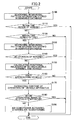
- FIG. 2 is a flowchart illustrating an example of a control process flow of the vehicle control system 10 according to this example of an embodiment of the present invention.
- the control process flow shown in FIG. 2 is repeated at every short period of predetermined time.
- the behavior estimation portion 15b of the control ECU 15 searches the behavioral pattern of the user stored in the behavior database 13 (S100).
- the behavior estimation portion 15b compares a time period of nonuse stored in the behavior database 13 with the present year, month, and day detected by the clock apparatus 16 so as to determine whether the present year, month, and day fall within the time period of nonuse (S110).
- the time period of nonuse as the behavioral pattern information may be a long time period of absence of the user in the behavior database 13.
- a user approaching determining process (described later) is not carried out, when the user is determined to be absent for a long time in the above determining process (S110). Therefore, since the vehicle apparatuses 14 are not activated, the system 100 is assuredly prevented from malfunctioning.
- the behavior estimation portion 15b determines that the present year, month, and date do not fall within the time period of nonuse (S110: No)
- the behavior estimation portion 15b compares the present year, month, and date with the time period of use in the behavioral pattern information stored in the behavior database 13 so as to determine whether the present year, month, and date fall within the time period of use in the behavioral pattern information (S120).
- the behavior estimation portion 15b determines that the present year, month, and date fall with the time period of nonuse (S110: Yes)
- this routine of the control process is completed.
- the in-vehicle transceiver 11 may be turned off since it is expected that no communications are to be carried out between the mobile phone 11 and the vehicle 100. With this, use of standby electricity can be reduced.
- the behavior estimation portion 15b determines that the present time detected by the clock apparatus 16 falls within the time period of use in the behavioral pattern information (S120: Yes)
- the behavior estimation portion 15b searches for a location of nonuse in the behavioral pattern information stored in the behavior database 13 so as to determine whether the current location 100 detected by the navigation apparatus 12 is in the location of nonuse (S140).
- the location of nonuse may be the airport parking lot, as stated above, as the behavioral pattern information in the behavior database 13.
- the user approaching determining process S160 (described later) is not carried out. Therefore, since the vehicle apparatuses 14 are not activated, the system 100 is assuredly prevented from malfunctioning during absence of the user due to, for example, a trip far away from the airport.
- the behavior estimation portion 15b determines that the vehicle 100 currently does not exist in the location of nonuse in the behavioral pattern information (S140: No)
- the behavior estimation portion 15b calculates a positional relationship between the current location of the mobile terminal 1 possessed by the user and the current location of the vehicle 100.
- the behavior estimation portion 15b may calculate the distance between the current location of the mobile terminal 1 and the current location of the vehicle 100, in accordance with the current location of the mobile terminal 1 transmitted from the mobile terminal 1 and the current location of the vehicle detected by the navigation apparatus 12 (S150).
- the behavior estimation portion 15b determines that the vehicle 100 is currently in the location of nonuse in the behavioral pattern information (S140: Yes)
- this routine of the control process in completed.
- the in-vehicle transceiver 11 may be turned off, similar to the above, thereby reducing standby electricity use.
- the controlling portion 15a determines whether the distance between the current location of the mobile terminal 1 and the current location of the vehicle 100, the distance having been calculated by the behavior estimation portion 15b, is within a predetermined distance (e.g., a distance in which the user can have visual contact with the vehicle 100), and whether the user carrying the mobile terminal 1 approaches the vehicle 100 (S160).
- a predetermined distance e.g., a distance in which the user can have visual contact with the vehicle 100
- the controlling portion 15a determines that the user carrying the mobile terminal 1 approaches the vehicle 100 (S160: Yes)
- the controlling portion 15a extracts the content about the operation of the vehicle apparatuses 14 to be operated, in accordance with the behavioral pattern information stored in the behavior database 13 (S170).
- the controlling portion 15a extracts the content about the operation of the vehicle apparatuses 14 corresponding to the present time detected by the clock apparatus 16 and the current location of the vehicle 100 detected by the navigation apparatus 12 in the behavioral pattern information stored in the behavior database 13.
- the behavior database 13 stores "time period of use: 7 am to 8 am, vehicle location: residence parking lot, content about operation of vehicle apparatuses 14: activating the air conditioner 14a" in an associated manner.
- the behavior estimation portion 15b extracts the content about the operation of the vehicle apparatuses 14, which is "activating the air conditioner 14a".
- the controlling portion 15a determines whether a temperature in the vehicle 100 detected by a temperature sensor 14f is lower than a predetermined set temperature (or in an operational range) (S180).
- the controlling portion 15a transmits to the air conditioner 14a a control signal for activating and starting air conditioning (S190).
- the air conditioner 14a starts air heating (pre-heating) so as to increase the temperature in the vehicle 100 to the predetermined set temperature range.
- this routine of the control process is completed.
- the controlling portion 15a of the control ECU 15 controls the vehicle apparatuses 14 in accordance with the behavioral pattern information of the user stored in the behavior database 13 and the positional relationship between the current location of the mobile terminal 1 and the current location of the vehicle 100.
- the vehicle apparatuses 14 can preferably be controlled in consideration of the behavioral pattern of the user and the positional relationship between the user carrying the mobile terminal 1 and the vehicle 100.
- the behavior database 13 that stores the behavioral pattern information of the user is arranged in the vehicle 100 in the above example, the behavior database 13 may be arranged in the mobile terminal 1 or the information center 2.
- new behavioral pattern information may be input to the behavior database 13 of the mobile terminal 1 and the pre-stored behavioral pattern information may be changed or deleted in the behavior database 13 of the mobile terminal 1 via the information center 2 or the input/output apparatus device 17 of the vehicle 100.
- new behavioral pattern information may be registered in the behavior database 13 of the information center 2 and the pre-stored behavioral pattern information may be changed or deleted in the behavior database 13 of the information center 2 via the mobile terminal 1 or the input/output apparatus device 17 of the vehicle 100.
- the above example may be configured so that new behavioral pattern information is registered in the behavior database 13 and the pre-stored behavioral pattern information is changed or deleted in the behavior database 13 only via the input/output apparatus device 17 arranged in the vehicle 100. With this, no communications are needed between the mobile terminal 1 or the information center 2 and the in-vehicle transceiver 11 at the time of registration, deletion, and/or change of the behavioral pattern information, thereby reducing telecommunication cost. Moreover, since external access to the behavior database 13 is restricted, the information in the behavior database 13 is kept highly confidential.
- the behavioral pattern information stored in the behavior database 13 is configured to be subjected to learnability. For example, times of the vehicle apparatus 14 being used, locations of the vehicle 100, and contents about the operations of the vehicle apparatuses 14 are automatically stored in the behavior database 13 and associated with one another in a probability (frequency) order. In this case, the behavior database 13 may update the behavioral pattern information that has already been stored, in accordance with such learning. With this, the behavioral pattern information that has been stored in the behavior database 13 may correspond to an actual behavioral pattern of the user.
- the controlling portion 15a of the control ECU 15 may control the security apparatus 14b so as to reduce the security level of the security apparatus 14b when the distance between the current location of the mobile terminal 1 and the current location of the vehicle 100 is within a predetermined distance, or when the user is in the vicinity of the vehicle 100 (the user can have visual contract with the vehicle 100, or the user is near the vehicle 100 so that he/she can immediately return to the vehicle 100).
- the security level of the vehicle 100 is preferably reduced, thereby securely preventing the security apparatus 14b from malfunctioning.
- the controlling portion 15a determines that the distance between the current location of the mobile terminal 1 transmitted from the mobile terminal 1 and the current location of the vehicle 100 detected by the navigation apparatus 12 is within a predetermined distance, the controlling portion 15a transmits a control signal so as to reduce the security level.
- controlling portion 15a of the control ECU 15 may control the vehicle apparatus 14 in accordance with the current location of the mobile terminal 1 transmitted from the mobile terminal 1.
- the controlling portion 15a may control so as to turn the in-vehicle transceiver 11 off when the controlling portion 15a determines that the mobile terminal 1 currently exists in a transport vehicle other than his/her vehicle (e.g., a train, another vehicle, an airplane, or the like).
- a transport vehicle other than his/her vehicle e.g., a train, another vehicle, an airplane, or the like.
- the controlling portion 15a of the control ECU 15 determines that the distance between the current location of the mobile terminal 1 and the current location of the vehicle 100 is within a predetermined distance (e.g., the user is in close range of the vehicle 100 but has difficulty in making visual contact with the vehicle 100)
- the controlling portion 15a transmits an instruction signal to the mobile terminal 1 so as to allow the mobile terminal 1 to display the location of the vehicle 100 on the display of the mobile terminal 1.
- the user can confirm the location of the vehicle 100 on the display of the mobile terminal 1 at an appropriate time.
- the present invention may be applicable to a vehicle control system that controls a vehicle apparatus installed in a vehicle, in accordance with a positional relationship between a current location of a mobile terminal and a current location of the vehicle. Appearance, weight, size, traveling performance, and the like of the vehicle in which the vehicle apparatus is installed are not considerations.
Landscapes
- Engineering & Computer Science (AREA)
- Mechanical Engineering (AREA)
- Computer Networks & Wireless Communication (AREA)
- Signal Processing (AREA)
- Radar, Positioning & Navigation (AREA)
- Remote Sensing (AREA)
- Traffic Control Systems (AREA)
- Telephonic Communication Services (AREA)
- Selective Calling Equipment (AREA)
- Navigation (AREA)
- Mobile Radio Communication Systems (AREA)
Claims (7)
- Fahrzeugsteuersystem (10) umfassend:ein mobiles Terminal (1), das einen gegenwärtigen Standort des mobilen Terminals überträgt,einen Empfangsabschnitt (11), der in einem Fahrzeug (100) installiert ist und den von dem mobilen Terminal übertragenen gegenwärtigen Standort empfängt,einen Fahrzeugstandortdetektionsabschnitt (12), der einen gegenwärtigen Standort des Fahrzeugs detektiert,einen Steuerabschnitt (15), der eine in dem Fahrzeug installierte Fahrzeugvorrichtung (14a, 14b, 14c, 14d, 14e) in Übereinstimmung mit einer Positionsbeziehung zwischen der durch den Empfangsabschnitt empfangenen gegenwärtigen Position des mobilen Terminals und dem durch den Fahrzeugstandortdetektionsabschnitt detektierten gegenwärtigen Standort des Fahrzeugs steuert,dadurch gekennzeichnet, daß das Fahrzeugsteuersystem ferner umfaßt:einen Speicherabschnitt (13), der automatisch Verhaltensmusterinformationen eines Nutzers des Fahrzeugs erzeugt und speichert,wobei der Steuerabschnitt (15) die Fahrzeugvorrichtung in Übereinstimmung mit den in dem Speicherabschnitt gespeicherten Verhaltensmusterinformationen und der Positionsbeziehung zwischen dem gegenwärtigen Standort des mobilen Terminals und dem gegenwärtigen Standort des Fahrzeugs steuert.
- Fahrzeugsteuersystem (10) nach Anspruch 1, wobei die in dem Speicherabschnitt gespeicherten Verhaltensmusterinformationen wenigstens eines von einer Zeit, wenn das Fahrzeug verwendet wird, einem Standort des Fahrzeugs und Informationen über den Betrieb der Fahrzeugvorrichtung umfassen.
- Fahrzeugsteuersystem nach Anspruch 1 oder 2, wobei der Empfangsabschnitt (11) und das mobile Terminal (1) über ein Informationszentrum (2) kommunizieren,
wobei der Speicherabschnitt (13) in einem von dem Fahrzeug (100), dem mobilen Terminal (1) und dem Informationszentrum (2) angeordnet ist, und
wobei die in dem Speicherabschnitt gespeicherten Verhaltensmusterinformationen einer von einer Registrierung, einer Änderung und
einer Löschung mittels einem/r von dem mobilen Terminal, dem Informationszentrum und einer in dem Fahrzeug angeordneten Eingabe-/Ausgabevorrichtung (17) unterzogen werden können. - Fahrzeugsteuersystem nach Anspruch 1 oder 2, wobei der Empfangsabschnitt (11) und das mobile Terminal (1) über ein Informationszentrum (2) kommunizieren,
wobei der Speicherabschnitt (13) in dem Fahrzeug (100) angeordnet ist, und
wobei die in dem Speicherabschnitt gespeicherten Verhaltensmusterinformationen einer von einer Registrierung, einer Änderung und einer Löschung mittels einer in dem Fahrzeug angeordneten Eingabe-/Ausgabevorrichtung (17) unterzogen werden können. - Fahrzeugsteuersystem nach Anspruch 2, wobei der Steuerabschnitt (15) einen Verhaltensabschätzabschnitt (15b) umfaßt, der Informationen über den Betrieb der Fahrzeugvorrichtung in Übereinstimmung mit den in dem Speicherabschnitt (13) gespeicherten Verhaltensmusterinformationen abschätzt, und
wobei die Informationen über den Betrieb der Fahrzeugvorrichtung, wobei die Informationen durch den Verhaltensabschätzabschnitt abgeschätzt werden, genutzt werden, wenn der Abstand zwischen dem gegenwärtigen Standort des mobilen Terminals und dem gegenwärtigen Standort des Fahrzeugs kleiner als ein vorbestimmter Abstand ist. - Fahrzeugsteuersystem nach Anspruch 5, wobei die Verhaltensmusterinformationen ferner einen Stillstandszeitraum umfassen, wenn das Fahrzeug nicht durch den Nutzer genutzt wird, und
wobei der Steuerabschnitt (15) verhindert, daß die Informationen über den Betrieb der Fahrzeugvorrichtung während des Stillstandszeitraum genutzt werden. - Fahrzeugsteuersystem nach Anspruch 5, wobei die Verhaltensmusterinformationen ferner einen Stillstandsort umfassen, an dem das Fahrzeug nicht durch den Nutzer genutzt wird, und
wobei der Steuerabschnitt (15) verhindert, daß die Informationen über den Betrieb der Fahrzeugvorrichtung genutzt werden, wenn das Fahrzeug (100) sich am Stillstandsort befindet.
Applications Claiming Priority (2)
| Application Number | Priority Date | Filing Date | Title |
|---|---|---|---|
| JP2006212458A JP4400599B2 (ja) | 2006-08-03 | 2006-08-03 | 車両制御システム |
| PCT/JP2007/065145 WO2008016104A1 (en) | 2006-08-03 | 2007-08-02 | Vehicle control system |
Publications (3)
| Publication Number | Publication Date |
|---|---|
| EP2048046A1 EP2048046A1 (de) | 2009-04-15 |
| EP2048046A4 EP2048046A4 (de) | 2010-08-25 |
| EP2048046B1 true EP2048046B1 (de) | 2013-06-12 |
Family
ID=38997278
Family Applications (1)
| Application Number | Title | Priority Date | Filing Date |
|---|---|---|---|
| EP20070791825 Active EP2048046B1 (de) | 2006-08-03 | 2007-08-02 | Fahrzeugsteuersystem |
Country Status (5)
| Country | Link |
|---|---|
| US (1) | US7912591B2 (de) |
| EP (1) | EP2048046B1 (de) |
| JP (1) | JP4400599B2 (de) |
| CN (1) | CN101351361B (de) |
| WO (1) | WO2008016104A1 (de) |
Cited By (1)
| Publication number | Priority date | Publication date | Assignee | Title |
|---|---|---|---|---|
| EP3825189A1 (de) | 2019-11-20 | 2021-05-26 | Volkswagen Ag | Diebstahlwarnsystem und diebstahlwarnverfahren |
Families Citing this family (22)
| Publication number | Priority date | Publication date | Assignee | Title |
|---|---|---|---|---|
| JP5347556B2 (ja) * | 2009-02-23 | 2013-11-20 | トヨタ自動車株式会社 | 飲酒検知装置 |
| JP5551388B2 (ja) * | 2009-07-21 | 2014-07-16 | トヨタ自動車株式会社 | 節電システム |
| US8907768B2 (en) * | 2009-11-25 | 2014-12-09 | Visa International Service Association | Access using a mobile device with an accelerometer |
| DE102009057926B4 (de) * | 2009-12-11 | 2014-04-24 | Continental Automotive Gmbh | Verfahren und Vorrichtung zum Schutz eines Fahrzeugs vor Diebstahl |
| DE102010004756A1 (de) * | 2010-01-14 | 2011-07-21 | Yazgan, Osman, 47800 | Verfahren zum Melden eines Diebstahls und/oder eines unbefugten Bewegens eines abgestellten Fahrzeuges |
| US9227483B2 (en) * | 2010-03-12 | 2016-01-05 | GM Global Technology Operations LLC | Vehicle connectivity systems, methods, and applications |
| JP5621852B2 (ja) * | 2010-11-11 | 2014-11-12 | トヨタ自動車株式会社 | 通信端末利用システム |
| CN102176768A (zh) * | 2010-12-28 | 2011-09-07 | 东莞宇龙通信科技有限公司 | 一种位置监测方法及装置 |
| EP2597838B1 (de) * | 2011-11-28 | 2018-09-05 | Lg Electronics Inc. | Mobiles endgerät und in einem auto angebrachte bildanzeigevorrichtung |
| US9417329B2 (en) * | 2012-03-19 | 2016-08-16 | Qualcomm Incorporated | User experience of the connected automobile |
| JP2014125098A (ja) * | 2012-12-26 | 2014-07-07 | Mitsubishi Motors Corp | 車載機器の遠隔操作システム |
| CN104442702B (zh) * | 2014-07-28 | 2020-07-28 | 冯林 | 一种汽车无钥匙进入系统 |
| CN104192094A (zh) * | 2014-08-28 | 2014-12-10 | 郑州瑞合信电子科技有限公司 | 一种车辆防盗方法和系统 |
| KR101610539B1 (ko) * | 2014-11-13 | 2016-04-07 | 현대자동차주식회사 | 차량용 공조장치의 증발기 표면의 미생물 번식 억제 장치 및 방법 |
| CN104590213B (zh) * | 2014-12-30 | 2017-10-20 | 钟志华 | 一种基于物联网的汽车发动机定位方法及系统 |
| JP6369362B2 (ja) * | 2015-03-13 | 2018-08-08 | 株式会社オートネットワーク技術研究所 | 車両用通信システム及び車載通信装置 |
| JP6267818B1 (ja) | 2017-03-27 | 2018-01-24 | 株式会社ラック | 処理装置、処理方法およびプログラム |
| EP3720741B1 (de) * | 2017-12-07 | 2022-03-16 | Toyota Motor Europe | Verfahren und vorrichtung zur sicherung eines fahrzeugs durch verhinderung von selbständiger entriegelung |
| CN110217186A (zh) * | 2018-03-02 | 2019-09-10 | 上海博泰悦臻网络技术服务有限公司 | 车辆自动启动方法及云端服务器 |
| US10909866B2 (en) * | 2018-07-20 | 2021-02-02 | Cybernet Systems Corp. | Autonomous transportation system and methods |
| KR102128410B1 (ko) * | 2018-12-10 | 2020-07-01 | 주식회사 성우하이텍 | 차량의 도어락 제어 시스템 및 그 방법 |
| JP2021172275A (ja) | 2020-04-28 | 2021-11-01 | トヨタ自動車株式会社 | 自動バレー駐車サービスの管理装置、サービス提供方法、及びサービス利用車両 |
Family Cites Families (14)
| Publication number | Priority date | Publication date | Assignee | Title |
|---|---|---|---|---|
| JPH06199191A (ja) * | 1992-12-28 | 1994-07-19 | Mazda Motor Corp | 自動車用制御装置の制御ゲイン変更方法及びその変更装置 |
| JPH06206475A (ja) * | 1993-01-09 | 1994-07-26 | Mazda Motor Corp | 自動車用制御装置の制御ゲイン変更装置 |
| DE19826904C2 (de) | 1998-06-17 | 2003-07-31 | Siemens Ag | Funkschlüssel |
| JP2001317398A (ja) | 2000-05-11 | 2001-11-16 | Auto Bank:Kk | 無線電話機の通信網を利用した車両の遠隔操作によるエンジン制御システム |
| JP2002083393A (ja) | 2000-09-07 | 2002-03-22 | Denso Corp | スケジュール管理システム及び車載装置 |
| JP2003042045A (ja) | 2001-07-27 | 2003-02-13 | Matsushita Electric Ind Co Ltd | 自動車用エンジン遠隔始動装置 |
| JP3948286B2 (ja) * | 2002-01-15 | 2007-07-25 | 日立建機株式会社 | 建設機械の管理システム及び管理方法 |
| JP4042567B2 (ja) | 2003-01-09 | 2008-02-06 | 株式会社デンソー | 車載無線通信装置 |
| JP4604461B2 (ja) * | 2003-05-20 | 2011-01-05 | パナソニック株式会社 | 電波受付装置、電波送信装置、および乗物 |
| DE10341286A1 (de) | 2003-09-04 | 2005-04-28 | Daimler Chrysler Ag | Zugangskontrollsystem für Fahrzeuge |
| JP2005318335A (ja) * | 2004-04-28 | 2005-11-10 | Toyota Infotechnology Center Co Ltd | 車両指示システム、プログラム、記録媒体および車両指示方法 |
| JP2005319911A (ja) * | 2004-05-10 | 2005-11-17 | Toyota Motor Corp | 遠隔制御装置及び遠隔制御方法 |
| JP4380459B2 (ja) * | 2004-08-05 | 2009-12-09 | トヨタ自動車株式会社 | 遠隔制御装置 |
| JP4225254B2 (ja) * | 2004-08-05 | 2009-02-18 | 株式会社日立製作所 | 列車制御システム及び地上システム |
-
2006
- 2006-08-03 JP JP2006212458A patent/JP4400599B2/ja not_active Expired - Fee Related
-
2007
- 2007-08-02 WO PCT/JP2007/065145 patent/WO2008016104A1/ja not_active Ceased
- 2007-08-02 EP EP20070791825 patent/EP2048046B1/de active Active
- 2007-08-02 US US11/992,165 patent/US7912591B2/en not_active Expired - Fee Related
- 2007-08-02 CN CN2007800010872A patent/CN101351361B/zh active Active
Cited By (1)
| Publication number | Priority date | Publication date | Assignee | Title |
|---|---|---|---|---|
| EP3825189A1 (de) | 2019-11-20 | 2021-05-26 | Volkswagen Ag | Diebstahlwarnsystem und diebstahlwarnverfahren |
Also Published As
| Publication number | Publication date |
|---|---|
| CN101351361A (zh) | 2009-01-21 |
| US20090265046A1 (en) | 2009-10-22 |
| WO2008016104A1 (en) | 2008-02-07 |
| EP2048046A4 (de) | 2010-08-25 |
| CN101351361B (zh) | 2011-06-08 |
| US7912591B2 (en) | 2011-03-22 |
| JP2008037215A (ja) | 2008-02-21 |
| EP2048046A1 (de) | 2009-04-15 |
| JP4400599B2 (ja) | 2010-01-20 |
Similar Documents
| Publication | Publication Date | Title |
|---|---|---|
| US7912591B2 (en) | Vehicle control system | |
| US8972079B2 (en) | Conditional vehicle remote starting | |
| US9316196B2 (en) | Vehicle controller | |
| US9230425B2 (en) | Vehicle controller | |
| US8325025B2 (en) | Automated geo-fence boundary configuration and activation | |
| US20130151036A1 (en) | Remote starter | |
| RU2700217C2 (ru) | Система планирования работы беспроводного маяка транспортного средства (варианты) | |
| CN108701065B (zh) | 控制设备、程序更新方法和计算机程序 | |
| CN104853965B (zh) | 用于通过服务供应商选择性地打开车辆的系统 | |
| US20090212978A1 (en) | System for managing a fleet of automotive vehicles | |
| US7613551B2 (en) | Vehicle remote operation device and method | |
| US9367048B2 (en) | Vehicle controller | |
| US10919490B1 (en) | Sustained neutral operation of vehicles | |
| US20140371951A1 (en) | Remote vehicle start system with advance dynamic scheduling system | |
| US20030073448A1 (en) | Terminal device and termainal device operation management system and operation management method | |
| CN111754688B (zh) | 车辆管理系统 | |
| US11284232B2 (en) | Vehicle control system | |
| US20160283896A1 (en) | Operating an inventory system of a vehicle | |
| JP4380459B2 (ja) | 遠隔制御装置 | |
| US7680572B2 (en) | Onboard-equipment control apparatus and onboard-equipment control system | |
| US10724866B2 (en) | Vehicle system, information processing device, and vehicle | |
| US10943482B2 (en) | Selection of identifiers | |
| CN117605359B (zh) | 车门控制方法、装置、车辆及计算机可读存储介质 | |
| CN101163615A (zh) | 远程操作系统、远程操作设备以及服务中心 | |
| JP3692132B2 (ja) | 車両運行管理システム |
Legal Events
| Date | Code | Title | Description |
|---|---|---|---|
| PUAI | Public reference made under article 153(3) epc to a published international application that has entered the european phase |
Free format text: ORIGINAL CODE: 0009012 |
|
| 17P | Request for examination filed |
Effective date: 20080331 |
|
| AK | Designated contracting states |
Kind code of ref document: A1 Designated state(s): AT BE BG CH CY CZ DE DK EE ES FI FR GB GR HU IE IS IT LI LT LU LV MC MT NL PL PT RO SE SI SK TR |
|
| AX | Request for extension of the european patent |
Extension state: AL BA HR MK RS |
|
| RBV | Designated contracting states (corrected) |
Designated state(s): DE FR GB |
|
| A4 | Supplementary search report drawn up and despatched |
Effective date: 20100723 |
|
| DAX | Request for extension of the european patent (deleted) | ||
| GRAP | Despatch of communication of intention to grant a patent |
Free format text: ORIGINAL CODE: EPIDOSNIGR1 |
|
| RAP1 | Party data changed (applicant data changed or rights of an application transferred) |
Owner name: TOYOTA JIDOSHA KABUSHIKI KAISHA |
|
| GRAS | Grant fee paid |
Free format text: ORIGINAL CODE: EPIDOSNIGR3 |
|
| GRAA | (expected) grant |
Free format text: ORIGINAL CODE: 0009210 |
|
| AK | Designated contracting states |
Kind code of ref document: B1 Designated state(s): DE FR GB |
|
| REG | Reference to a national code |
Ref country code: GB Ref legal event code: FG4D |
|
| RIN1 | Information on inventor provided before grant (corrected) |
Inventor name: SEKIYAMA, HIROAKI Inventor name: NAMBA, TOSHIYUKI |
|
| REG | Reference to a national code |
Ref country code: DE Ref legal event code: R096 Ref document number: 602007031036 Country of ref document: DE Effective date: 20130808 |
|
| PLBE | No opposition filed within time limit |
Free format text: ORIGINAL CODE: 0009261 |
|
| STAA | Information on the status of an ep patent application or granted ep patent |
Free format text: STATUS: NO OPPOSITION FILED WITHIN TIME LIMIT |
|
| 26N | No opposition filed |
Effective date: 20140313 |
|
| REG | Reference to a national code |
Ref country code: DE Ref legal event code: R097 Ref document number: 602007031036 Country of ref document: DE Effective date: 20140313 |
|
| REG | Reference to a national code |
Ref country code: DE Ref legal event code: R084 Ref document number: 602007031036 Country of ref document: DE |
|
| REG | Reference to a national code |
Ref country code: GB Ref legal event code: 746 Effective date: 20150603 |
|
| REG | Reference to a national code |
Ref country code: FR Ref legal event code: PLFP Year of fee payment: 10 |
|
| REG | Reference to a national code |
Ref country code: FR Ref legal event code: PLFP Year of fee payment: 11 |
|
| REG | Reference to a national code |
Ref country code: FR Ref legal event code: PLFP Year of fee payment: 12 |
|
| P01 | Opt-out of the competence of the unified patent court (upc) registered |
Effective date: 20230427 |
|
| PGFP | Annual fee paid to national office [announced via postgrant information from national office to epo] |
Ref country code: GB Payment date: 20250612 Year of fee payment: 19 |
|
| PGFP | Annual fee paid to national office [announced via postgrant information from national office to epo] |
Ref country code: FR Payment date: 20250610 Year of fee payment: 19 |
|
| PGFP | Annual fee paid to national office [announced via postgrant information from national office to epo] |
Ref country code: DE Payment date: 20250611 Year of fee payment: 19 |