EP2043208A2 - Optische Kommunikationslichtquelleneinheit und Wellenlängenüberwachungssteuerverfahren - Google Patents
Optische Kommunikationslichtquelleneinheit und Wellenlängenüberwachungssteuerverfahren Download PDFInfo
- Publication number
- EP2043208A2 EP2043208A2 EP08018484A EP08018484A EP2043208A2 EP 2043208 A2 EP2043208 A2 EP 2043208A2 EP 08018484 A EP08018484 A EP 08018484A EP 08018484 A EP08018484 A EP 08018484A EP 2043208 A2 EP2043208 A2 EP 2043208A2
- Authority
- EP
- European Patent Office
- Prior art keywords
- optical output
- drive current
- twenty
- output power
- light emitting
- Prior art date
- Legal status (The legal status is an assumption and is not a legal conclusion. Google has not performed a legal analysis and makes no representation as to the accuracy of the status listed.)
- Granted
Links
Images


Classifications
-
- H—ELECTRICITY
- H01—ELECTRIC ELEMENTS
- H01S—DEVICES USING THE PROCESS OF LIGHT AMPLIFICATION BY STIMULATED EMISSION OF RADIATION [LASER] TO AMPLIFY OR GENERATE LIGHT; DEVICES USING STIMULATED EMISSION OF ELECTROMAGNETIC RADIATION IN WAVE RANGES OTHER THAN OPTICAL
- H01S5/00—Semiconductor lasers
- H01S5/06—Arrangements for controlling the laser output parameters, e.g. by operating on the active medium
- H01S5/068—Stabilisation of laser output parameters
- H01S5/0683—Stabilisation of laser output parameters by monitoring the optical output parameters
- H01S5/0687—Stabilising the frequency of the laser
-
- H—ELECTRICITY
- H01—ELECTRIC ELEMENTS
- H01S—DEVICES USING THE PROCESS OF LIGHT AMPLIFICATION BY STIMULATED EMISSION OF RADIATION [LASER] TO AMPLIFY OR GENERATE LIGHT; DEVICES USING STIMULATED EMISSION OF ELECTROMAGNETIC RADIATION IN WAVE RANGES OTHER THAN OPTICAL
- H01S5/00—Semiconductor lasers
- H01S5/06—Arrangements for controlling the laser output parameters, e.g. by operating on the active medium
- H01S5/068—Stabilisation of laser output parameters
- H01S5/0683—Stabilisation of laser output parameters by monitoring the optical output parameters
-
- H—ELECTRICITY
- H01—ELECTRIC ELEMENTS
- H01S—DEVICES USING THE PROCESS OF LIGHT AMPLIFICATION BY STIMULATED EMISSION OF RADIATION [LASER] TO AMPLIFY OR GENERATE LIGHT; DEVICES USING STIMULATED EMISSION OF ELECTROMAGNETIC RADIATION IN WAVE RANGES OTHER THAN OPTICAL
- H01S5/00—Semiconductor lasers
- H01S5/06—Arrangements for controlling the laser output parameters, e.g. by operating on the active medium
- H01S5/0617—Arrangements for controlling the laser output parameters, e.g. by operating on the active medium using memorised or pre-programmed laser characteristics
-
- H—ELECTRICITY
- H01—ELECTRIC ELEMENTS
- H01S—DEVICES USING THE PROCESS OF LIGHT AMPLIFICATION BY STIMULATED EMISSION OF RADIATION [LASER] TO AMPLIFY OR GENERATE LIGHT; DEVICES USING STIMULATED EMISSION OF ELECTROMAGNETIC RADIATION IN WAVE RANGES OTHER THAN OPTICAL
- H01S5/00—Semiconductor lasers
- H01S5/06—Arrangements for controlling the laser output parameters, e.g. by operating on the active medium
- H01S5/068—Stabilisation of laser output parameters
- H01S5/06804—Stabilisation of laser output parameters by monitoring an external parameter, e.g. temperature
Definitions
- the device temperature is coarsely adjusted using the means 13 for automatically controlling the device temperature such that the device temperature is maintained at a given target value as shown in Fig. 2(a) , and thereby the optical output wavelength ⁇ is put in a pull-in range 25 shown in Fig. 2(b) corresponding to optical output separately specified wavelength ⁇ s of the wavelength locker 15.
- the means 12 for automatically controlling the optical output power such that the optical output power is maintained at a given target value is simultaneously operated to set and control the optical output power at the separately specified value while the optical output wavelength is maintained in the pull-in range 25.
- the intersection point of the isoplethic curves (two open curves) concerning the optical output wavelength characteristics and optical output power characteristics of each light emitting device is determined directly and uniquely by utilizing the "monotonous" optical output wavelength characteristics and optical output power characteristics.
- the intersection point is used as a target values (target value "it” for the drive current in automatic control and target value Tt for the device temperature in the automatic control) in automatically controlling the operating conditions (the drive current or optical output power and the device temperature) of each light emitting device.
- the first aspect of the invention also relates to a configuration and an operating procedure for realizing the determination of the intersection point and the use of the intersection point as the target value.
- means for monitoring the drive current of the light emitting device is monitored to make comparison determination whether or not the drive current is located in a specific allowable fluctuation range, the means predicting the dependence of the optical output power on the drive current and device temperature in the drive current fluctuation of the light emitting device based on the comparison determination result, is provided in the optical communication light source unit.
- the complicated adjustment and control and the extremely expensive optical components are not required, and the automatic adjustment and control can simply be performed automatically at a moderate price such that both the optical output wavelength and the optical output power become the specified values.
- the second optical communication light source unit can sufficiently be applied to the access system or metropolitan area system in which the low cost and the simplification are required.
- the communication light source unit according to the second aspect of the invention is suitable to a light source unit applied to dense wavelength division multiplexing (DWDM) communication in which high stabilization is required to the optical output wavelength for a long term.
- DWDM dense wavelength division multiplexing
- a measuring point 361 i s1 ,T s1
- a measuring point 362 i s1 ,T s2
- a measuring point 363 i s2 ,T s1
- a measuring point 364 i s2 ,T s2
- three points in the above four points can be selected as the measuring point to determine the coefficient of the linear function in the three-dimensional space.
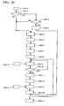
- the reference numeral 101 designates the eleventh means including a light emitting device such as LD to emit the light.
- the reference numeral 102 designates the twelfth means for automatically controlling the drive current or optical output power of the light emitting device constituting the eleventh means 101 by feedback control or the like such that the drive current or optical output power is maintained at a given target value.
- the reference numeral 103 designates the thirteenth means for automatically controlling the device temperature of the light emitting device constituting the eleventh means 101 by the feedback control or the like such that the device temperature is maintained at a given target value.
- the case in which the dependence of the optical output wavelength and optical output power of the light emitting device on the drive current and the dependence of the optical output wavelength and optical output power on the device temperature are well expressed by the planes (linear function of drive current and device temperature) is described for the sake of simplification.
- the dependence of the optical output wavelength and optical output power of the light emitting device on the drive current and the dependence of the optical output wavelength and optical output power on the device temperature are well expressed by a quadratic surface or a more general function, or well expressed by a plane or a curved surface in each of divided plural regions, the coefficients of the functions expressing the characteristics can numerically be determined by the similar procedure, so that the effect of the invention is not changed.
- Fig. 7 shows an operating procedure of the second embodiment. The portions which are different from the operating procedure shown in Fig. 5 will mainly be described below.
- the seventeenth means 107 monitors both the optical output wavelength and optical output power of the light a1 from the eleventh means 101 which is driven while the drive current or optical output power c1 and the device temperature d1 are set as the target values.
- the drive current or optical output power c1 and the device temperature d1 are determined by the fifteenth means 105.
- the reference numeral 205 designates the twenty-fifth means for monitoring the drive current of the light emitting device constituting the twenty-first means 201.
- the twenty-fifth means 205 makes the comparison determination whether or not the drive current is located in the separately specified allowable fluctuation range.
- thetwenty-fifthmeans205 predictstherelationshipamong the drive current, device temperature, and optical output power in the drive current fluctuation of the light emitting device from the relationship among the drive current, device temperature, and optical output power of the light emitting device.
- the relationship among is determined at least one value for the light emitting device constituting the twenty-first means 201, the value being stored in the twenty-fourth means 204.
- the reference numeral 206 designates the twenty-sixth means for determining the latest drive current or optical output power and the latest device temperature at which both the optical output wavelength and the optical output power in the drive current fluctuation of the light emitting device become the separately specifiedvalues from the relationship among the drive current, device temperature, and optical output wavelength determined by at least one value stored in the twenty-fourth means 204 for the light emitting device constituting the twenty-first means 201 and the relationship among the drive current, device temperature, and optical output power in the drive current fluctuation of the light emitting device predicted by the twenty-fifth means 205.
- the optical output wavelength value of the light emitting device, stored in the twenty-fourth means 204, for the determined drive current and device temperature are read and inputted to the twenty-sixth means 206.
- the eighth embodiment shown in Fig. 24 differs from the seventh embodiment shown in Fig. 23 in the procedures S302-2 and S302-3, although the procedures S302-1 and S302-4 in the eighth embodiment are similar to the procedures S301-1 and S301-4 in the seventh embodiment.
- the portions different from the seventh embodiment of Fig. 23 will mainly be described below.
Landscapes
- Physics & Mathematics (AREA)
- Condensed Matter Physics & Semiconductors (AREA)
- General Physics & Mathematics (AREA)
- Electromagnetism (AREA)
- Optics & Photonics (AREA)
- Semiconductor Lasers (AREA)
- Optical Communication System (AREA)
Applications Claiming Priority (3)
| Application Number | Priority Date | Filing Date | Title |
|---|---|---|---|
| JP2005075245A JP4081095B2 (ja) | 2005-03-16 | 2005-03-16 | 光通信用光源部に格納する光出力波長特性及び光出力電力特性の測定点の選定方法 |
| JP2005236375A JP4064986B2 (ja) | 2005-08-17 | 2005-08-17 | 光出力波長特性、光出力電力特性及びrf振幅特性の測定点の選定方法 |
| EP06712946A EP1772932B1 (de) | 2005-03-16 | 2006-02-02 | Lichtquelle für optische kommunikation und verfahren zur überwachung/steuerung ihrer wellenlänge |
Related Parent Applications (2)
| Application Number | Title | Priority Date | Filing Date |
|---|---|---|---|
| EP06712946A Division EP1772932B1 (de) | 2005-03-16 | 2006-02-02 | Lichtquelle für optische kommunikation und verfahren zur überwachung/steuerung ihrer wellenlänge |
| EP06712946.0 Division | 2006-02-02 |
Publications (3)
| Publication Number | Publication Date |
|---|---|
| EP2043208A2 true EP2043208A2 (de) | 2009-04-01 |
| EP2043208A3 EP2043208A3 (de) | 2009-12-09 |
| EP2043208B1 EP2043208B1 (de) | 2011-05-25 |
Family
ID=36991450
Family Applications (5)
| Application Number | Title | Priority Date | Filing Date |
|---|---|---|---|
| EP08018484A Expired - Fee Related EP2043208B1 (de) | 2005-03-16 | 2006-02-02 | Optische Kommunikationslichtquelleneinheit und Wellenlängenüberwachungssteuerverfahren |
| EP12002642.2A Expired - Fee Related EP2479854B1 (de) | 2005-03-16 | 2006-02-02 | Optische Kommunikationslichtquelleneinheit |
| EP09014055A Expired - Fee Related EP2146408B1 (de) | 2005-03-16 | 2006-02-02 | Lichtquelle für optische Kommunikation und Verfahren zur Steuerung ihrer Wellenlänge |
| EP06712946A Expired - Fee Related EP1772932B1 (de) | 2005-03-16 | 2006-02-02 | Lichtquelle für optische kommunikation und verfahren zur überwachung/steuerung ihrer wellenlänge |
| EP09014056.7A Expired - Fee Related EP2146409B1 (de) | 2005-03-16 | 2006-02-02 | Lichtquelle für optische Kommunikation |
Family Applications After (4)
| Application Number | Title | Priority Date | Filing Date |
|---|---|---|---|
| EP12002642.2A Expired - Fee Related EP2479854B1 (de) | 2005-03-16 | 2006-02-02 | Optische Kommunikationslichtquelleneinheit |
| EP09014055A Expired - Fee Related EP2146408B1 (de) | 2005-03-16 | 2006-02-02 | Lichtquelle für optische Kommunikation und Verfahren zur Steuerung ihrer Wellenlänge |
| EP06712946A Expired - Fee Related EP1772932B1 (de) | 2005-03-16 | 2006-02-02 | Lichtquelle für optische kommunikation und verfahren zur überwachung/steuerung ihrer wellenlänge |
| EP09014056.7A Expired - Fee Related EP2146409B1 (de) | 2005-03-16 | 2006-02-02 | Lichtquelle für optische Kommunikation |
Country Status (7)
| Country | Link |
|---|---|
| US (1) | US7869717B2 (de) |
| EP (5) | EP2043208B1 (de) |
| KR (1) | KR100865428B1 (de) |
| CN (1) | CN101867152B (de) |
| CA (1) | CA2560143C (de) |
| DE (1) | DE602006011692D1 (de) |
| WO (1) | WO2006098094A1 (de) |
Families Citing this family (5)
| Publication number | Priority date | Publication date | Assignee | Title |
|---|---|---|---|---|
| JP6048204B2 (ja) * | 2013-02-20 | 2016-12-21 | 株式会社リコー | 情報処理装置、情報処理システム、及び情報処理プログラム |
| JP2016096191A (ja) * | 2014-11-12 | 2016-05-26 | 住友電気工業株式会社 | 光送信器及び駆動電流制御方法 |
| WO2019116660A1 (ja) * | 2017-12-15 | 2019-06-20 | 株式会社堀場製作所 | 半導体レーザ装置、半導体レーザ装置の駆動方法及び駆動プログラム |
| JP7118141B2 (ja) * | 2018-05-09 | 2022-08-15 | 三菱電機株式会社 | 光送信モジュールの調整検査システム、光送信モジュールの調整検査方法、および光送信モジュールの製造方法 |
| JP2021111678A (ja) * | 2020-01-09 | 2021-08-02 | 富士通株式会社 | レーザ波長制御装置及びレーザ波長制御方法 |
Family Cites Families (20)
| Publication number | Priority date | Publication date | Assignee | Title |
|---|---|---|---|---|
| US5077748A (en) | 1991-04-01 | 1991-12-31 | International Business Machines Corporation | Laser system and method |
| JP3218999B2 (ja) | 1996-12-18 | 2001-10-15 | 安藤電気株式会社 | 外部共振器型波長可変半導体レーザ光源 |
| JPH11163462A (ja) | 1997-11-27 | 1999-06-18 | Hitachi Ltd | 光波長安定制御装置、光送信器、光波長多重送信器 |
| JP3445176B2 (ja) * | 1998-12-24 | 2003-09-08 | 富士通株式会社 | 光送信機 |
| JP2000323785A (ja) * | 1999-05-10 | 2000-11-24 | Nec Corp | 半導体レーザモジュールの制御装置及びその制御方法 |
| US6580531B1 (en) * | 1999-12-30 | 2003-06-17 | Sycamore Networks, Inc. | Method and apparatus for in circuit biasing and testing of a modulated laser and optical receiver in a wavelength division multiplexing optical transceiver board |
| JP4103287B2 (ja) | 2000-02-14 | 2008-06-18 | 横河電機株式会社 | Dfbレーザ駆動装置、dfbレーザ駆動方法、及び記憶媒体 |
| US6807206B2 (en) * | 2001-04-16 | 2004-10-19 | The Furukawa Electric Co., Ltd. | Semiconductor laser device and drive control method for a semiconductor laser device |
| US6850398B2 (en) | 2001-06-07 | 2005-02-01 | Xicor, Inc. | Feed forward programmable current controller |
| JP2003008138A (ja) * | 2001-06-13 | 2003-01-10 | Motorola Inc | レーザーダイオード制御装置 |
| US7120183B2 (en) * | 2001-07-11 | 2006-10-10 | Optium Corporation | Electro-absorption modulated laser with high operating temperature tolerance |
| JP2003086889A (ja) | 2001-09-10 | 2003-03-20 | Opnext Japan Inc | 半導体レーザ装置 |
| JP3815995B2 (ja) * | 2001-10-11 | 2006-08-30 | 松下電器産業株式会社 | 光送信装置および光波長割り当て方法 |
| CN1192520C (zh) | 2002-01-30 | 2005-03-09 | 华为技术有限公司 | 数字调节光发送模块及其调节方法 |
| JP2003224326A (ja) * | 2002-01-30 | 2003-08-08 | Ntt Electornics Corp | レーザダイオード制御用半導体集積回路および光送信モジュールならびに光出力設定方法 |
| EP1345296A1 (de) | 2002-03-16 | 2003-09-17 | Agilent Technologies, Inc. (a Delaware corporation) | System zur Leistungskontrol, Wellenlänge und Extinktionsratio in ioptischen Quellen und Rechnerprogram dafür |
| US6885685B2 (en) | 2002-06-11 | 2005-04-26 | Sumitomo Electric Industries, Ltd. | Control system for a laser diode and a method for controlling the same |
| JP3810008B2 (ja) * | 2002-07-09 | 2006-08-16 | ユーディナデバイス株式会社 | 光通信モジュール、波長ロッカーモジュール、その設定値取得装置及び設定値取得方法、並びにそのプログラム及びそのプログラムを記録した記録媒体 |
| JP4108400B2 (ja) | 2002-07-24 | 2008-06-25 | 富士通株式会社 | 電界吸収型光変調器を備えた半導体レーザモジュールの駆動回路および駆動方法 |
| US7460572B2 (en) * | 2003-05-13 | 2008-12-02 | Nippon Telegraph And Telephone Corporation | Optical module and method for monitoring and controlling wavelengths |
-
2006
- 2006-02-02 EP EP08018484A patent/EP2043208B1/de not_active Expired - Fee Related
- 2006-02-02 CN CN2010101639298A patent/CN101867152B/zh not_active Expired - Fee Related
- 2006-02-02 CA CA002560143A patent/CA2560143C/en not_active Expired - Fee Related
- 2006-02-02 EP EP12002642.2A patent/EP2479854B1/de not_active Expired - Fee Related
- 2006-02-02 EP EP09014055A patent/EP2146408B1/de not_active Expired - Fee Related
- 2006-02-02 EP EP06712946A patent/EP1772932B1/de not_active Expired - Fee Related
- 2006-02-02 DE DE602006011692T patent/DE602006011692D1/de active Active
- 2006-02-02 KR KR1020067021872A patent/KR100865428B1/ko not_active IP Right Cessation
- 2006-02-02 WO PCT/JP2006/301803 patent/WO2006098094A1/ja not_active Application Discontinuation
- 2006-02-02 EP EP09014056.7A patent/EP2146409B1/de not_active Expired - Fee Related
- 2006-02-02 US US11/568,109 patent/US7869717B2/en not_active Expired - Fee Related
Non-Patent Citations (3)
| Title |
|---|
| A. ZADOK ET AL.: "Spectral shift and broadening of DFB lasers under direct modulation", IEEE PHOTON. TECHNOL. LETT., vol. 10, no. 12, 1998, pages 1709 - 1711, XP000802162, DOI: doi:10.1109/68.730477 |
| POWER SOURCE(TM) TUNABLE HIGH POWER CW LASER MODULE WITH INTEGRATED WAVELENGTH MONITORING, 23 July 2004 (2004-07-23), Retrieved from the Internet <URL:http://www.avanex.com/Products/appnotes/PwrSource.1935> |
| TAKAGI ET AL., 25 GHZ-SPACING INTERVAL WAVELENGTH MONITOR INTEGRATED DFB LASER MODULE, 2002, pages 349 |
Also Published As
| Publication number | Publication date |
|---|---|
| KR20070065260A (ko) | 2007-06-22 |
| CN101867152A (zh) | 2010-10-20 |
| DE602006011692D1 (de) | 2010-03-04 |
| WO2006098094A1 (ja) | 2006-09-21 |
| EP1772932A4 (de) | 2008-08-13 |
| US7869717B2 (en) | 2011-01-11 |
| EP2479854A2 (de) | 2012-07-25 |
| KR100865428B1 (ko) | 2008-10-24 |
| EP2479854B1 (de) | 2013-09-18 |
| US20090161708A1 (en) | 2009-06-25 |
| CA2560143A1 (en) | 2006-09-21 |
| EP2146408A2 (de) | 2010-01-20 |
| EP1772932A1 (de) | 2007-04-11 |
| EP2043208A3 (de) | 2009-12-09 |
| EP2146408A3 (de) | 2010-05-26 |
| EP1772932B1 (de) | 2010-01-13 |
| CA2560143C (en) | 2009-06-23 |
| EP2146409B1 (de) | 2013-09-18 |
| EP2146409A2 (de) | 2010-01-20 |
| EP2146408B1 (de) | 2012-07-04 |
| CN101867152B (zh) | 2011-10-05 |
| EP2043208B1 (de) | 2011-05-25 |
| EP2146409A3 (de) | 2010-05-26 |
| EP2479854A3 (de) | 2012-09-19 |
Similar Documents
| Publication | Publication Date | Title |
|---|---|---|
| US6928092B2 (en) | Method and apparatus for active numeric temperature compensation of an etalon in a wavelength stabilized laser | |
| EP1624543B1 (de) | Optisches modul und verfahren zum überwachen und steuern einer wellenlänge | |
| US6400737B1 (en) | Automatic closed-looped gain adjustment for a temperature tuned, wavelength stabilized laser source in a closed-loop feedback control system | |
| US6233262B1 (en) | Device and method for monitoring and controlling laser wavelength | |
| US20070258494A1 (en) | Wavelength Control of Laser Light | |
| EP2043208B1 (de) | Optische Kommunikationslichtquelleneinheit und Wellenlängenüberwachungssteuerverfahren | |
| JP2009081512A (ja) | 光送信装置および設定値決定方法 | |
| US20060239306A1 (en) | Characterization and non-invasive correction of operational control currents of a tuneable laser | |
| CN1300123A (zh) | 稳定激光波长的方法和装置 | |
| US10673205B2 (en) | Wavelength tunable laser module and method of controlling wavelength thereof | |
| CN107086432B (zh) | 波长可变型激光器模块及其波长控制方法 | |
| CA2592373C (en) | Optical communication light source unit and wavelength monitoring control method | |
| JP4081095B2 (ja) | 光通信用光源部に格納する光出力波長特性及び光出力電力特性の測定点の選定方法 | |
| JP4141714B2 (ja) | 半導体レーザ装置 | |
| JP2018190874A (ja) | 半導体レーザ光源 | |
| GB2380058A (en) | Telecommunication laser transmitter systems and methods of operating such systems | |
| JP6815885B2 (ja) | 波長可変光源の制御装置および制御方法 | |
| JP2007053184A (ja) | 直接変調型光通信用光源部、並びに直接変調型光通信用光源部に格納する光出力波長特性、光出力電力特性及びrf振幅特性の測定点の選定方法 | |
| US20030113058A1 (en) | Control system for dynamic gain equalization filter | |
| JP2004228368A (ja) | 直接変調方式を用いた波長可変光源制御回路及び方法 | |
| US20020176453A1 (en) | System for fine tuning of a wavelength produced by a laser diode |
Legal Events
| Date | Code | Title | Description |
|---|---|---|---|
| PUAI | Public reference made under article 153(3) epc to a published international application that has entered the european phase |
Free format text: ORIGINAL CODE: 0009012 |
|
| 17P | Request for examination filed |
Effective date: 20081022 |
|
| AC | Divisional application: reference to earlier application |
Ref document number: 1772932 Country of ref document: EP Kind code of ref document: P |
|
| AK | Designated contracting states |
Kind code of ref document: A2 Designated state(s): DE FR GB IT |
|
| PUAL | Search report despatched |
Free format text: ORIGINAL CODE: 0009013 |
|
| AK | Designated contracting states |
Kind code of ref document: A3 Designated state(s): DE FR GB IT |
|
| AKX | Designation fees paid |
Designated state(s): DE FR GB IT |
|
| GRAP | Despatch of communication of intention to grant a patent |
Free format text: ORIGINAL CODE: EPIDOSNIGR1 |
|
| GRAS | Grant fee paid |
Free format text: ORIGINAL CODE: EPIDOSNIGR3 |
|
| GRAA | (expected) grant |
Free format text: ORIGINAL CODE: 0009210 |
|
| AC | Divisional application: reference to earlier application |
Ref document number: 1772932 Country of ref document: EP Kind code of ref document: P |
|
| AK | Designated contracting states |
Kind code of ref document: B1 Designated state(s): DE FR GB IT |
|
| REG | Reference to a national code |
Ref country code: GB Ref legal event code: FG4D |
|
| REG | Reference to a national code |
Ref country code: DE Ref legal event code: R096 Ref document number: 602006022239 Country of ref document: DE Effective date: 20110707 |
|
| PLBE | No opposition filed within time limit |
Free format text: ORIGINAL CODE: 0009261 |
|
| STAA | Information on the status of an ep patent application or granted ep patent |
Free format text: STATUS: NO OPPOSITION FILED WITHIN TIME LIMIT |
|
| 26N | No opposition filed |
Effective date: 20120228 |
|
| REG | Reference to a national code |
Ref country code: DE Ref legal event code: R097 Ref document number: 602006022239 Country of ref document: DE Effective date: 20120228 |
|
| REG | Reference to a national code |
Ref country code: FR Ref legal event code: PLFP Year of fee payment: 10 |
|
| REG | Reference to a national code |
Ref country code: FR Ref legal event code: PLFP Year of fee payment: 11 |
|
| REG | Reference to a national code |
Ref country code: FR Ref legal event code: PLFP Year of fee payment: 12 |
|
| REG | Reference to a national code |
Ref country code: FR Ref legal event code: PLFP Year of fee payment: 13 |
|
| PGFP | Annual fee paid to national office [announced via postgrant information from national office to epo] |
Ref country code: GB Payment date: 20180216 Year of fee payment: 13 Ref country code: DE Payment date: 20180219 Year of fee payment: 13 |
|
| PGFP | Annual fee paid to national office [announced via postgrant information from national office to epo] |
Ref country code: IT Payment date: 20180227 Year of fee payment: 13 Ref country code: FR Payment date: 20180223 Year of fee payment: 13 |
|
| REG | Reference to a national code |
Ref country code: DE Ref legal event code: R119 Ref document number: 602006022239 Country of ref document: DE |
|
| GBPC | Gb: european patent ceased through non-payment of renewal fee |
Effective date: 20190202 |
|
| PG25 | Lapsed in a contracting state [announced via postgrant information from national office to epo] |
Ref country code: DE Free format text: LAPSE BECAUSE OF NON-PAYMENT OF DUE FEES Effective date: 20190903 Ref country code: GB Free format text: LAPSE BECAUSE OF NON-PAYMENT OF DUE FEES Effective date: 20190202 |
|
| PG25 | Lapsed in a contracting state [announced via postgrant information from national office to epo] |
Ref country code: IT Free format text: LAPSE BECAUSE OF NON-PAYMENT OF DUE FEES Effective date: 20190202 Ref country code: FR Free format text: LAPSE BECAUSE OF NON-PAYMENT OF DUE FEES Effective date: 20190228 |