EP2039892A1 - Dispositif de vanne de moteur - Google Patents
Dispositif de vanne de moteur Download PDFInfo
- Publication number
- EP2039892A1 EP2039892A1 EP07767439A EP07767439A EP2039892A1 EP 2039892 A1 EP2039892 A1 EP 2039892A1 EP 07767439 A EP07767439 A EP 07767439A EP 07767439 A EP07767439 A EP 07767439A EP 2039892 A1 EP2039892 A1 EP 2039892A1
- Authority
- EP
- European Patent Office
- Prior art keywords
- valve
- hydraulic
- engine
- piston
- hydraulic oil
- Prior art date
- Legal status (The legal status is an assumption and is not a legal conclusion. Google has not performed a legal analysis and makes no representation as to the accuracy of the status listed.)
- Granted
Links
Images


Classifications
-
- F—MECHANICAL ENGINEERING; LIGHTING; HEATING; WEAPONS; BLASTING
- F01—MACHINES OR ENGINES IN GENERAL; ENGINE PLANTS IN GENERAL; STEAM ENGINES
- F01L—CYCLICALLY OPERATING VALVES FOR MACHINES OR ENGINES
- F01L13/00—Modifications of valve-gear to facilitate reversing, braking, starting, changing compression ratio, or other specific operations
- F01L13/0015—Modifications of valve-gear to facilitate reversing, braking, starting, changing compression ratio, or other specific operations for optimising engine performances by modifying valve lift according to various working parameters, e.g. rotational speed, load, torque
-
- F—MECHANICAL ENGINEERING; LIGHTING; HEATING; WEAPONS; BLASTING
- F01—MACHINES OR ENGINES IN GENERAL; ENGINE PLANTS IN GENERAL; STEAM ENGINES
- F01L—CYCLICALLY OPERATING VALVES FOR MACHINES OR ENGINES
- F01L1/00—Valve-gear or valve arrangements, e.g. lift-valve gear
- F01L1/12—Transmitting gear between valve drive and valve
- F01L1/14—Tappets; Push rods
- F01L1/146—Push-rods
-
- F—MECHANICAL ENGINEERING; LIGHTING; HEATING; WEAPONS; BLASTING
- F01—MACHINES OR ENGINES IN GENERAL; ENGINE PLANTS IN GENERAL; STEAM ENGINES
- F01L—CYCLICALLY OPERATING VALVES FOR MACHINES OR ENGINES
- F01L1/00—Valve-gear or valve arrangements, e.g. lift-valve gear
- F01L1/12—Transmitting gear between valve drive and valve
- F01L1/18—Rocking arms or levers
- F01L1/181—Centre pivot rocking arms
-
- F—MECHANICAL ENGINEERING; LIGHTING; HEATING; WEAPONS; BLASTING
- F01—MACHINES OR ENGINES IN GENERAL; ENGINE PLANTS IN GENERAL; STEAM ENGINES
- F01L—CYCLICALLY OPERATING VALVES FOR MACHINES OR ENGINES
- F01L13/00—Modifications of valve-gear to facilitate reversing, braking, starting, changing compression ratio, or other specific operations
- F01L13/06—Modifications of valve-gear to facilitate reversing, braking, starting, changing compression ratio, or other specific operations for braking
-
- F—MECHANICAL ENGINEERING; LIGHTING; HEATING; WEAPONS; BLASTING
- F01—MACHINES OR ENGINES IN GENERAL; ENGINE PLANTS IN GENERAL; STEAM ENGINES
- F01L—CYCLICALLY OPERATING VALVES FOR MACHINES OR ENGINES
- F01L9/00—Valve-gear or valve arrangements actuated non-mechanically
- F01L9/10—Valve-gear or valve arrangements actuated non-mechanically by fluid means, e.g. hydraulic
-
- F—MECHANICAL ENGINEERING; LIGHTING; HEATING; WEAPONS; BLASTING
- F01—MACHINES OR ENGINES IN GENERAL; ENGINE PLANTS IN GENERAL; STEAM ENGINES
- F01M—LUBRICATING OF MACHINES OR ENGINES IN GENERAL; LUBRICATING INTERNAL COMBUSTION ENGINES; CRANKCASE VENTILATING
- F01M1/00—Pressure lubrication
- F01M1/16—Controlling lubricant pressure or quantity
-
- F—MECHANICAL ENGINEERING; LIGHTING; HEATING; WEAPONS; BLASTING
- F01—MACHINES OR ENGINES IN GENERAL; ENGINE PLANTS IN GENERAL; STEAM ENGINES
- F01L—CYCLICALLY OPERATING VALVES FOR MACHINES OR ENGINES
- F01L1/00—Valve-gear or valve arrangements, e.g. lift-valve gear
- F01L1/20—Adjusting or compensating clearance
-
- F—MECHANICAL ENGINEERING; LIGHTING; HEATING; WEAPONS; BLASTING
- F01—MACHINES OR ENGINES IN GENERAL; ENGINE PLANTS IN GENERAL; STEAM ENGINES
- F01L—CYCLICALLY OPERATING VALVES FOR MACHINES OR ENGINES
- F01L1/00—Valve-gear or valve arrangements, e.g. lift-valve gear
- F01L1/26—Valve-gear or valve arrangements, e.g. lift-valve gear characterised by the provision of two or more valves operated simultaneously by same transmitting-gear; peculiar to machines or engines with more than two lift-valves per cylinder
- F01L1/267—Valve-gear or valve arrangements, e.g. lift-valve gear characterised by the provision of two or more valves operated simultaneously by same transmitting-gear; peculiar to machines or engines with more than two lift-valves per cylinder with means for varying the timing or the lift of the valves
-
- F—MECHANICAL ENGINEERING; LIGHTING; HEATING; WEAPONS; BLASTING
- F01—MACHINES OR ENGINES IN GENERAL; ENGINE PLANTS IN GENERAL; STEAM ENGINES
- F01L—CYCLICALLY OPERATING VALVES FOR MACHINES OR ENGINES
- F01L1/00—Valve-gear or valve arrangements, e.g. lift-valve gear
- F01L1/34—Valve-gear or valve arrangements, e.g. lift-valve gear characterised by the provision of means for changing the timing of the valves without changing the duration of opening and without affecting the magnitude of the valve lift
- F01L1/344—Valve-gear or valve arrangements, e.g. lift-valve gear characterised by the provision of means for changing the timing of the valves without changing the duration of opening and without affecting the magnitude of the valve lift changing the angular relationship between crankshaft and camshaft, e.g. using helicoidal gear
- F01L1/3442—Valve-gear or valve arrangements, e.g. lift-valve gear characterised by the provision of means for changing the timing of the valves without changing the duration of opening and without affecting the magnitude of the valve lift changing the angular relationship between crankshaft and camshaft, e.g. using helicoidal gear using hydraulic chambers with variable volume to transmit the rotating force
- F01L2001/34423—Details relating to the hydraulic feeding circuit
- F01L2001/34426—Oil control valves
-
- F—MECHANICAL ENGINEERING; LIGHTING; HEATING; WEAPONS; BLASTING
- F01—MACHINES OR ENGINES IN GENERAL; ENGINE PLANTS IN GENERAL; STEAM ENGINES
- F01L—CYCLICALLY OPERATING VALVES FOR MACHINES OR ENGINES
- F01L1/00—Valve-gear or valve arrangements, e.g. lift-valve gear
- F01L1/34—Valve-gear or valve arrangements, e.g. lift-valve gear characterised by the provision of means for changing the timing of the valves without changing the duration of opening and without affecting the magnitude of the valve lift
- F01L1/344—Valve-gear or valve arrangements, e.g. lift-valve gear characterised by the provision of means for changing the timing of the valves without changing the duration of opening and without affecting the magnitude of the valve lift changing the angular relationship between crankshaft and camshaft, e.g. using helicoidal gear
- F01L1/3442—Valve-gear or valve arrangements, e.g. lift-valve gear characterised by the provision of means for changing the timing of the valves without changing the duration of opening and without affecting the magnitude of the valve lift changing the angular relationship between crankshaft and camshaft, e.g. using helicoidal gear using hydraulic chambers with variable volume to transmit the rotating force
- F01L2001/34423—Details relating to the hydraulic feeding circuit
- F01L2001/34446—Fluid accumulators for the feeding circuit
-
- F—MECHANICAL ENGINEERING; LIGHTING; HEATING; WEAPONS; BLASTING
- F01—MACHINES OR ENGINES IN GENERAL; ENGINE PLANTS IN GENERAL; STEAM ENGINES
- F01L—CYCLICALLY OPERATING VALVES FOR MACHINES OR ENGINES
- F01L13/00—Modifications of valve-gear to facilitate reversing, braking, starting, changing compression ratio, or other specific operations
- F01L13/0015—Modifications of valve-gear to facilitate reversing, braking, starting, changing compression ratio, or other specific operations for optimising engine performances by modifying valve lift according to various working parameters, e.g. rotational speed, load, torque
- F01L2013/0089—Modifications of valve-gear to facilitate reversing, braking, starting, changing compression ratio, or other specific operations for optimising engine performances by modifying valve lift according to various working parameters, e.g. rotational speed, load, torque with means for delaying valve closing
-
- F—MECHANICAL ENGINEERING; LIGHTING; HEATING; WEAPONS; BLASTING
- F01—MACHINES OR ENGINES IN GENERAL; ENGINE PLANTS IN GENERAL; STEAM ENGINES
- F01L—CYCLICALLY OPERATING VALVES FOR MACHINES OR ENGINES
- F01L2305/00—Valve arrangements comprising rollers
Definitions
- the present invention relates to an engine valve device and technology allowing variable motion of the engine valve device.
- FIG. 7 is a sectional side view showing a structure of a known engine valve device.
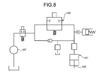
- FIG. 8 is a circuit diagram showing a configuration of a fluid circuit of the engine valve device shown in FIG. 7 .
- an engine valve device 100 is configured to maintain an open state of an intake valve 103 by a fluid actuator 101 via a rocker arm 102.
- this engine valve device 100 includes the fluid actuator 101 that follows the rocker arm 102, a direction control valve 105 that stops a flow of fluid from fluid actuator 101 at a predetermined timing, and a fluid source that supplies fluid to the direction control valve 105.
- the direction control valve 105 stops the flow of fluid from the fluid actuator 101 at the predetermined timing, and the fluid actuator 101 acts on the rocker arm 102. Therefore, the engine valve device 100 can maintain the open state of the intake valve 103.
- the fluid source used as such usage is, for example shown in FIG. 8 , a part of a lubrication unit 107, which is attached to the engine to supply lubricating oil to the engine, and is capable of supplying pressurized oil of a pressure from about 210 KPa to 620 KPa.
- a pump may be provided separately from the lubrication unit 107 attached to the engine to supply pressurized oil of a pressure from 10 MPa to 35 MPa to the direction control valve 105 (for example, see Patent Document 1).
- Patent Document 1 Japanese Patent Application Laid-Open No. 2003-328715
- a piston 106 cannot follow an open-close motion of the intake valve 103 when the engine is at a high revolution, for example, over 1000 rpm. Therefore, the piston 106 can not reach to a predetermined position and can not put the intake valve into the open state at a desired amount of opening.
- the pump is provided separately from the lubrication unit 107 attached to the engine to supply pressurized oil of a pressure from 10 MPa to 35 MPa, it is subject to a considerable increase in cost as well as the engine becomes larger. Also, because the lubrication unit 107 attached to the engine supplies and discharges pressurized oil every time the fluid actuator 101 acts on, an energy loss becomes tremendously large.
- the present invention is made in view of the above problems and an object of the present invention is to provide an engine valve device which is capable of following a high revolution of an engine and of highly efficient operating although the engine valve device is configured to vary a motion, utilizing a part of a lubricating oil unit attached to the engine as an oil source.
- an engine valve device includes a cam which rotates by engaging with a crankshaft, a rocker arm which follows a movement of the cam, and an intake valve which opens and closes an intake port by interacting the rocker arm and a spring.
- the engine valve device comprises: a piston which is movable in a same direction as the intake valve; a cylinder which houses the piston such that the piston is movable inside the cylinder; a hydraulic actuator including the piston and the cylinder; a hydraulic pipe line which communicates with a pressure chamber formed by the piston and the cylinder; an accumulation unit which accumulates hydraulic oil flowed out from the pressure chamber via the hydraulic pipe line; and an electromagnetic on-off valve which controls a flow of the hydraulic oil between the pressure chamber and the accumulation unit.
- the hydraulic actuator, the hydraulic pipe line, the accumulation unit, and the electromagnetic on-off valve make up a hydraulic circuit.
- the electromagnetic on-off valve is arranged on the hydraulic pipe line between the hydraulic actuator and the accumulation unit.
- an engine valve device includes a cam which rotates by engaging with a crankshaft, a rocker arm which follows a movement of the cam, an intake valve which opens or closes an intake port by interacting the rocker arm and a spring, and a hydraulic circuit.
- the hydraulic circuit includes: a hydraulic actuator which is activated by an open and close motion of the intake valve, the hydraulic actuator stopping a closing motion of the intake valve in an open state when hydraulic oil is sealed in a pressure chamber; an accumulation unit which accumulates the hydraulic oil flowed out from the pressure chamber of the hydraulic actuator when the intake valve moves to close, and which provides the hydraulic oil to the pressure chamber of the hydraulic actuator when the intake valve moves to open; and an electromagnetic on-off valve which controls a flow of the hydraulic oil from the hydraulic actuator to the accumulation unit.
- the electromagnetic on-off valve is arranged between the hydraulic actuator and the accumulation unit.
- the invention described above further comprises a hydraulic oil supply unit which provides the hydraulic oil to the hydraulic circuit.
- the hydraulic oil supply unit is a lubrication unit which provides lubricating oil to an engine and is attached to the engine.
- the invention described above further comprises an auxiliary pipe line which allows the flow of the hydraulic oil from the pressure chamber of the hydraulic actuator to the accumulation unit.
- the auxiliary pipe line includes a port which opens when the piston of the hydraulic actuator comes to a predetermined interval, the piston of the hydraulic actuator follows the intake valve moving to a closing direction.
- the invention described above further comprises a check valve which supplies the hydraulic oil from the hydraulic oil supply unit to the hydraulic circuit only if an oil pressure of the hydraulic circuit is lower than that of the hydraulic oil supply unit, and the check valve is arranged between the hydraulic oil supply unit and the hydraulic circuit.
- the pressure chamber of the hydraulic actuator is configured to cushion a shock when the intake valve closes.
- the invention described above further comprises: a push rod which transmits motion from the cam to the rocker arm, the push rod being disposed between the cam and the rocker arm; and a biasing unit which biases the rocker arm to tightly contact with the push rod.
- the engine valve device includes the hydraulic circuit including the accumulation unit which accumulates hydraulic oil flowed out from the pressure chamber of the hydraulic actuator when the intake valve moves to close, and provides hydraulic oil to the pressure chamber of the hydraulic actuator when the intake valve moves to open, and the electromagnetic on-off valve which controls a flow of the hydraulic oil from the hydraulic actuator to the accumulation unit.
- the electromagnetic on-off valve is arranged between the hydraulic actuator and the accumulation unit. Accordingly, to precisely make the intake valve an open state, the engine valve device can follow a high revolution of the engine and be efficiently operated.
- the lubrication unit which is attached to the engine and provides lubricating oil to the engine, provides hydraulic oil to the hydraulic circuit. Accordingly, there is no need to provide an oil pump separately from the lubrication unit attached to the engine, there is no need to grow in size, and an increase in cost is suppressed.
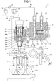
- FIG. 1 is a schematic view of an engine valve device according to an embodiment of the present invention
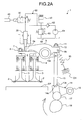
- FIG. 2 is a view showing a behavior of the engine valve device shown in FIG. 1
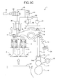
- FIG. 3 is a view showing a hydraulic circuit of the engine valve device shown in FIG. 1
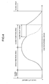
- FIG. 4 is a view showing a relationship between a cam rotating angle and an amount of valve lift for an intake stroke of the engine valve device shown in FIG. 1
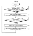
- FIG. 5 is a flowchart showing control of the engine valve device shown in FIG. 1
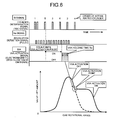
- FIG. 6 is a timing chart showing control timing of the engine valve device shown in FIG. 1
- An engine valve device 1 according to an embodiment of the present invention is applied to an engine valve device of a four-cycle diesel engine.
- the diesel engine includes a cylinder block and a cylinder head CH.
- the cylinder block is provided with a cylindrically shaped cylinder which allows an engine piston EP slides in up-and-down direction.
- the cylinder head is provides with a pair of intake ports 2 which are in communication with an outside of the cylinder and a pair of exhaust ports which is not shown in the figure.
- an intake valve 3 is provided such that the intake valve 3 closes or opens the intake port 2 by moving up and down with respect to FIG. 1 .
- an exhaust valve is provided such that the exhaust valve closes or opens the exhaust port by moving up and down.
- the intake valve 3 and the exhaust valve are poppet valves which are formed in an umbrella shape, and include valve portions (umbrella shaped portion) 3a that close the intake port 2 and the exhaust port and stems (rod shaped portion) 3b that slides through the cylinder head CH.
- the stem 3b of the intake valve 3 which is in communication with the intake port 2 is provided with a valve spring 4, and the valve portion 3a of the intake valve 3 is biased to close the intake port 2.
- the stem of the exhaust valve which is in communication with the exhaust port is provided with a valve spring, not shown in the figure, and the valve portion of the exhaust valve is biased to close the exhaust port.
- a crosshead 5 which has a side view of a T shape and pushes the ends of stems of the pair of the intake valves 3 at the same time is provides.
- the crosshead 5 is guided by a shaft 6 provided to be placed parallel to a moving direction of the intake valve 3 and the exhaust valve, and is allowed to move up and down with respect to FIG. 1 . Therefore, the crosshead 5 pushes the ends of the stems of the intake valves 3 to open the intake valves 3 against biasing forces of the valve springs 4 when the crosshead 5 moves down.
- One side of arm 5a of the crosshead 5 (left side arm in FIG. 1 ) is provided with an adjustable screw 7 such that the crosshead 5 closely contacts with the intake valve 3.
- the adjustable screw 7 can be screwed with respect to the crosshead 5 to adjust a clearance of one of the pear of the intake valves 3 (left side intake valve in FIG. 1 ).
- it is adjustable such that one of the intake valves 3 opens the intake port 2 at the same time the other of the intake valves 3 opens the intake port 2.
- a locknut 8 is threadably mounted on the adjustable screw 7 to prevent from loosening by closely sticking the locknut 8 to the crosshead 5 after adjusting.
- a rocker arm 9 is provided above the crosshead 5 as shown in FIG. 1 .
- the rocker arm 9 is rotatable around a rocker shaft 10 as an axis.
- the rocker arm 9 includes a pressing portion 9a which pushes the crosshead 5 on an end portion (left side portion in FIG. 1 ) and an action portion 9b on the other end portion.
- the pressing portion 9a of the rocker arm 9 is allowed to push around a central portion of the crosshead 5.
- the intake valve 3 opens the intake port 2.
- the intake valve 3 closes the intake port 2 by the biasing force of the valve spring 4 and moves up the crosshead 5.
- a groove 9c which has a planar view of a U shape is formed on a central portion of the pressing portion 9a.
- An adjust screw 11 is threadably mounted on the action portion 9b of the rocker arm 9 to adjust a clearance between the pressing portion 9a and the crosshead 5.
- the adjust screw 11 includes a hemisphere portion on an end portion and a male screw on the other end portion.
- a locknut 12 is threadably mounted on the adjust screw 11 which is threadably mounted on the other end portion of the rocker arm 9. The adjust screw 11 is allowed to prevent from loosening by closely sticking the locknut 12 to the rocker arm 9.
- the end portion of hemisphere of the adjust screw 11 is housed in an end portion of a push rod 13.
- the end portion of the push rod 13 is provided with a concave portion 13a of hemisphere and has a capacity of housing the end portion of hemisphere of the adjust screw 11.
- the push rod 13 rotates the rocker arm 9 counterclockwise with respect to FIG. 1 .
- the other end portion 13b of the push rod 13 is housed in a push rod housing 14a provided above an arm portion of a tappet arm 14.
- a return spring 15 is tacked between the action portion 9b of the rocker arm 9 and the cylinder head CH.
- the return spring 15 pushes the rocker arm 9 clockwise with respect to FIG. 1 , and is capable of maintaining to house the end portion of the adjust screw 11 in the concave portion 13a of the push rod 13. Meanwhile, the return spring 15 is to push the rocker arm 9 clockwise with respect to FIG. 1 , and the return spring 15 is replaced by a torsion coil spring which is wound around the rocker shaft 10. In this case, an end of the coil spring is fixed to the rocker arm 9, and the other end is fixed to the cylinder head CH.
- a tappet arm 14 is rotatably attached to a tappet shaft as an axis.
- the tappet arm 14 rotates clockwise with respect to FIG. 2
- the tappet arm 14 pushes up the push rod 13 and causes the rocker arm 9 to rotate counterclockwise with respect to FIG. 2 .
- a roller follower 17 is rotatably attached below an arm portion of the tappet arm 14, below the roller follower 17, a cam 18 is rotatably provided to allow a rolling contact with the roller follower 17.
- the cam 18 rotates by engaging with a crankshaft, not shown in the figure, of the engine.
- the cam 18 moves (lifts) the intake valve 3 via the tappet arm 14, the push rod 13, the rocker arm 9, and the crosshead 5, thereby, allowing the intake port 2 to open.
- an opening timing of the intake port 2 and a valve lift amount of the intake valve 3 are controlled by a surface configuration (cam profile) of the cam 18.
- the valve lift amount describes an action toward an open direction at a closing time of 0 as a lift, and takes a positive value at the moment.
- the crankshaft is connected to the other end portion of a con-rod of which an end portion is connected to the engine piston EP sliding in the cylinder.
- the intake valve 3 can be opened and closed in the intake stroke, and the intake valve 3 can be closed in a compression stroke, a combustion stroke, and an exhaust stroke.
- an hydraulic actuator 20 is provided above the crosshead 5.
- the hydraulic actuator 20 is arranged such that a tip of a rod portion 23c of a piston 23 contacts with the crosshead 5 and is capable of engaging with a movement of the crosshead 5.
- the hydraulic actuator 20 pushes the crosshead 5 at a predetermined timing and maintains an open state of the intake valve 3 regardless of movements of the cam 18, the tappet arm 14, the push rod 13, and the rocker arm 9.
- the hydraulic actuator 20 applied to the embodiment is a single acting type.
- a cylinder portion 22 is integrally formed with a block 21, and an electromagnetic on-off valve 30 can be housed to be attached.
- a supply discharge pipe line 21d which communicates with an output port 30b of the electromagnetic on-off valve 30 is formed on the block 21. Also, a first pipe line 21b which communicates with an output port 50a of an accumulator 50, which will be explained later in detail, is formed. The first pipe line 21b communicates with an intake port 30a of the electromagnetic on-off valve 30 and a flow pipe line 21e, which will be explained later in detail, by a second pipe line 21c.
- the cylinder portion 22 includes a small diameter chamber 22a and a large diameter chamber 22b, which constitute a pressure chamber and have cylindrical shapes.
- One end of the large diameter chamber 22b is opened to accept an insertion of the piston 23, and closed by the piston 23.
- the other end of the large diameter chamber 22b is formed such that the small diameter chamber 22a coincides and communicates with an axis of the large diameter chamber 22b.
- the small diameter chamber 22a communicates with the supply discharge pipe line 21d.
- a step 22c is formed on a border of the large diameter chamber 22b and the small diameter chamber 22a.
- An oil groove 22b1 is formed on a predetermined section of the large diameter chamber 22b.
- the flow pipe line 21e which communicates with a second pipe line 21c is formed on the oil groove 22b1.
- the cylinder portion 22 houses the piston 23 which slides in an axial direction of the large diameter chamber 22b and the small diameter chamber 22a (up and down direction with respect to FIG. 1 ).
- the piston 23 includes a piston portion 23a, a buffering portion 23b, and a rod portion 23c.
- the piston portion 23a is a portion which slides in the large diameter chamber 22b of the cylinder portion 22.
- the buffering portion 23b is a portion which is housed in the small diameter chamber 22a of the cylinder portion 22, and is provided to one end of axial direction (above the piston portion in FIG. 1 ) of the piston portion 23a.
- the buffering portion 23b is capable of, by interaction between the buffering portion 23b and the small diameter chamber 22a of the cylinder portion 22, cushioning a shock caused when the intake valve 3 closes.
- the pressure chamber is configured to cushion the shock caused when the intake valve 3 is closed.
- the buffering portion 23b includes a buffering shape which cushions the shock caused when the intake valve 3 is closed (when the intake valve 3 seats).
- the buffering shape is, for example, a plurality of longitudinal grooves 23b1 (four longitudinal grooves in this embodiment) which are formed from a circumferential root to a tip of the buffering portion 23b.
- the buffering shape is not limited to the longitudinal groove 23b1, and may be formed in a tapered shape which gradually tapers from the circumferential root to the tip of the buffering portion 23b. Also, the buffering shape may be formed in a tapered shape in which the small diameter chamber 22a gradually gets thick from a bottom portion to the large diameter chamber 22b.
- the rod portion 23c is a portion which extends outside of the cylinder portion 22, and is provided to an end opposite to the buffering portion 23b in axial direction of the piston portion 23a (below the piston portion 23a with respect to FIG. 1 ).
- the rod portion 23c is formed in a taper shape which gradually tapers from the root to the tip.
- the rod portion 23c is capable of pushing the crosshead 5 without interference of the rocker arm 9 by inserting the groove 9c formed on the pressing portion 9a of the rocker arm 9.
- the rod portion 23c is capable of pushing the crosshead 5 separately from the rocker arm 9.
- a gap sensor (clearance measurement means) 24 is provided on a side of the rod portion 23c of the piston 23.
- the gap sensor 24 measures a clearance between the rod portion 23c and the gap sensor 24, and is connected to an engine control unit (ECU) 40.
- the gap sensor 24 is capable of measuring the clearance, for example, by measuring a current surge.
- the engine control unit 40 is capable of monitoring an action of the hydraulic actuator 20 by monitoring the clearance of the rod portion 23c measured by the gap sensor 24. To be more specific, since the clearance becomes small when the rod portion 23c protrudes from the cylinder portion 22, and the clearance becomes large when the rod portion 23c recedes in the cylinder portion 22, the monitoring of the hydraulic actuator 20 can be achieved by monitoring the clearance.
- the electromagnetic on-off valve 30 is housed in the concave portion 21a of the block 21.
- the electromagnetic on-off valve 30 is a two port type electromagnetic on-off valve which includes an intake port 30a and an output port 30b.
- the intake port 30a communicates with the second pipe line 21c of the block 21, and the output port 30b communicates with the supply discharge pipe line 21d of the block 21.
- the electromagnetic on-off valve 30 includes inside a spool 31 as well as a spring and a solenoid, not shown in the figure.
- the spring pushes the spool 31 to connect the intake port 30a and the output port 30b when a normal condition, and the spool 31 cuts off the communication between the intake port 30a and the output port 30b against a biasing force of the spring when the solenoid is excited.
- the electromagnetic on-off valve 30 is capable of switching between a hydraulic oil supply discharge condition and a hydraulic oil cut off condition.
- the intake port 30a and the output port 30b returns to a condition in which the intake port 30a and the output port 30b are in communication.
- the piston 23 moves upward and hydraulic oil flows out from the supply discharge pipe line 21d of the block 21.
- the flowed hydraulic oil flows out outside of the hydraulic actuator 20 via the output port 30b and intake port 30a of the electromagnetic on-off valve 30, the second pipe line 21c, and the first pipe line 21b.
- the buffering portion 23b of the piston 23 is housed in the small diameter chamber 22a of the cylinder portion 22, and a sequence of functions of the hydraulic actuator 20 ends.
- the electromagnetic on-off valve 30 is connected to the engine control unit 40.
- the engine control unit 40 controls an exciting timing and an exciting time period of the electromagnetic on-off valve 30, and is capable of controlling the electromagnetic on-off valve 30 in units of milliseconds (1/1000 seconds) as desired.
- An output port 50a of the accumulator 50 is connected to the first pipe line 21b of the block 21.
- the accumulator 50 is an accumulating means for accumulating oil pressure, and the accumulator 50 according to the embodiment is a mechanical accumulator.
- the accumulator 50 includes the output port 50a explained above, an output pipe line 50b which extends from the output port 50a, an input pipe line 50c which crosses to the output pipe line 50b, and a input port 50d which communicates with the input pipe line 50c.
- the input pipe line 50c communicates with a pressure accumulating portion 52.
- the pressure accumulating portion 52 includes a cylinder 55 formed on a body of the accumulator 50.
- the cylinder 55 communicates with the input pipe line 50c, and is configured such that hydraulic oil provided from the input port 50d and hydraulic oil provided from the output port 50a can flow in.
- the cylinder 55 includes inside a plunger 56 which slides in an axial direction of the cylinder 55 and a compression spring 57 which pushes the plunger 56 toward a bottom wall of the cylinder 55 (toward left in the figure).
- hydraulic oil is provided from the input port 50d of the accumulator 50 and hydraulic oil pushes plunger 56 toward the side (right side with respect to FIG. 1 ), the plunger 56 can not resist a basing force of the compression spring 57, and hydraulic oil flows out from the output port 50a.
- hydraulic oil which is flowed out from the hydraulic actuator 20 and posses a higher oil pressure than an oil pressure of hydraulic oil provided from the input port 50d, is provided from the output port 50a of the accumulator 50, the hydraulic oil pushes the plunger 56 toward the side (right side with respect to FIG. 1 ), and the plunger 56 moves toward the side (toward left in the figure) against the biasing force of the compression spring 57.
- hydraulic oil is accumulated (pressure accumulation) in the pressure accumulating portion 52.
- the hydraulic actuator 20, the electromagnetic on-off valve 30, and the accumulator 50 make up a hydraulic circuit 60, as shown in FIG. 3 .
- a lubrication unit 61 which is attached to the engine and provides lubricating oil to the engine is capable of providing low pressure hydraulic oil to the hydraulic circuit 60.
- a check valve 62 is arranged between the lubrication unit 61 attached to the engine and the hydraulic circuit 60. The check valve 62 allows providing hydraulic oil to the hydraulic circuit 60 from the lubrication unit 61 attached to the engine only if an oil pressure of the hydraulic circuit 60 is lower than that of the lubrication unit 61 attached to the engine, and does not allow hydraulic oil to flow from the hydraulic circuit 60 side to the lubrication unit 61 attached to the engine.
- a relief valve 63 is provided between the check valve 62 and the hydraulic circuit 60 explained above.
- the relief valve 63 is capable of discharging hydraulic oil of the hydraulic circuit 60 to an oil pan 64 of the engine when the oil pressure of the hydraulic circuit 60 becomes higher than a predetermined pressure.
- the engine control unit 40 connected to the gap sensor 24 and the electromagnetic on-off valve 30 is configured to detect which cylinder has the engine piston EP come to a top dead center, based on a cylinder determination signal (G signal) entered from TDC (Top Dead Center) sensor (cylinder determination signal output means), as shown in FIG. 6 . Also, the engine control unit 40 calculates a revolution based on a revolution detection signal (Ne signal) entered from a crank angle sensor (revolution detection signal output means), not shown in the figure. The engine control unit 40 is configured to start to count number of pulses of the revolution detection signal (square wave) when the engine piston EP of a cylinder to delay a closing timing (for example, cylinder 5 in FIG. 6 ) comes to the upper dead center.
- the engine control unit 40 turns on a VVA activation signal and excites the electromagnetic on-off valve 30 for a preset VVA holding time Tw.
- the lubrication unit 61 attached to the engine provides hydraulic oil to the hydraulic circuit 60 by starting the engine.
- hydraulic oil is provided to in order of the accumulator 50, the electromagnetic on-off valve 30, and the hydraulic actuator 20 via the check valve 62.
- hydraulic oil is filled in the electromagnetic on-off valve 30 and the hydraulic actuator 20.
- the intake valve 3 opens and closes the intake port 2 during the intake stroke of the engine, and the intake valve 3 closes the intake port 2 during the compression stroke, the combustion stroke, and the exhaust stroke of the engine.
- the intake valve 3 closes the intake port 2 by the biasing force of the valve spring 4.
- a relation between a rotational angle of the cam 14 and the valve lift amount has a relation shown by a close area in FIG. 4 . More specifically, it has a relation in which the valve lift amount is 0 regardless of the rotational angle of the cam 18.
- the rod portion 23c of the piston 23 gradually protrudes (downward with respect to FIG. 1 ), contacting with the crosshead 5, by gradually providing hydraulic oil accumulated in the accumulator 50 to the small diameter chamber 22a and the large diameter chamber 22b of the cylinder portion 22.
- hydraulic oil is provided to in order of the electromagnetic on-off valve 30 and the hydraulic actuator 20.
- hydraulic oil is gradually provided to the hydraulic circuit 60 from the lubrication unit 61 attached to the engine via the check valve 62.
- a relation between the cam rotational angle and the valve lift amount has a relation shown by a close function area in FIG. 4 . More specifically, it has a relation in which the valve lift amount gradually decreases as the rotational angle of the cam 18 increases.
- the hydraulic actuator 20 has a function of a piston pump. To be more specific, hydraulic oil is accumulated in the accumulator 50 via the electromagnetic on-off valve 30 and the hydraulic actuator 20.
- the spool 31 cuts off the communication between the intake port 30a and the output port 30b against the biasing force of the spring. More specifically, the electromagnetic on-off valve 30 makes a transition from the hydraulic oil supply discharge state to the hydraulic oil cut off state. Then, the piston 23 is pushed into the cylinder portion 22 until the piston portion 23a of the piston 23 closes the oil groove 22b1 communicated with the flow pipe line 21e of the block 21, and, afterward, hydraulic oil is sealed in the small diameter chamber 22a and the large diameter chamber 22b of the cylinder portion 22. Thus, the piston 23 is stopped by hydraulic oil sealed in the small diameter chamber 22a and the large diameter chamber 22b.
- the rod portion 23c of the piston 23 pushes the crosshead 5, and the intake valve 3 keeps to open at a predetermined gate opening, as shown in FIG. 2D . More specifically, the closing timing of the intake port 2 by the intake valve 3 during the intake stroke is delayed. Because of a mechanism in which the oil groove 22b1 is provided inside the cylinder portion 22 and the piston portion 23a closes the oil groove 22b1, the open state is maintained at the same gate opening. At this time, a relation between the cam rotational angle and the valve lift amount has a relation shown by a close delay area in FIG. 4 . More specifically, it has a relation in which the valve lift amount is constant although the rotational angle of the cam 18 increases.
- the intake port 30a becomes in communication with the output port 30b again.
- the intake valve 3 gradually closes the intake port 2 by the biasing force of the valve spring 4.
- the engine control unit 40 starts to count the number of pulses of the revolution detection signal (Step S2), when the engine piston EP of the cylinder to delay a closing timing (for example, cylinder 5 in FIG. 6 ) comes to the upper dead center (Step S1: Yes), as shown in FIG. 5 and FIG. 6 . Then, when the counted number of pulses of the revolution detection signal reaches to the preset VVA activation setup pulse (Step S3: Yes), the engine control unit 40 turns on the VVA activation signal (Step S4).
- Step S5 the electromagnetic on-off valve 30 is excited for the preset VVA holding time Tw (Step S5). Afterward, these routines are repeated to control the closing timing of the intake port 2 to be delayed by the intake valve 3.
- the intake valve 3 engages with the rocker arm 9 until the piston 23 of the hydraulic actuator 20 closes the oil groove 22b1 (flow pipe line 21e). After closing the oil groove 22b1 which is communicated with the flow pipe line 21e, the open state of the intake valve 3 is maintained until the electromagnetic on-off valve 30 is opened. Thus, the open state of the intake port 2 is maintained at the preset amount of opening regardless of the closing timing of the electromagnetic on-off valve 30.
- an engine valve device of the present invention is applicable to an engine valve device which varies an action of an engine valve, especially, is adapted to an engine valve of a diesel engine.
Landscapes
- Engineering & Computer Science (AREA)
- Mechanical Engineering (AREA)
- General Engineering & Computer Science (AREA)
- Valve Device For Special Equipments (AREA)
Applications Claiming Priority (2)
| Application Number | Priority Date | Filing Date | Title |
|---|---|---|---|
| JP2006182121 | 2006-06-30 | ||
| PCT/JP2007/062630 WO2008001699A1 (fr) | 2006-06-30 | 2007-06-22 | Dispositif de vanne de moteur |
Publications (3)
| Publication Number | Publication Date |
|---|---|
| EP2039892A1 true EP2039892A1 (fr) | 2009-03-25 |
| EP2039892A4 EP2039892A4 (fr) | 2009-11-04 |
| EP2039892B1 EP2039892B1 (fr) | 2012-03-21 |
Family
ID=38845464
Family Applications (1)
| Application Number | Title | Priority Date | Filing Date |
|---|---|---|---|
| EP07767439A Expired - Fee Related EP2039892B1 (fr) | 2006-06-30 | 2007-06-22 | Dispositif de vanne de moteur |
Country Status (6)
| Country | Link |
|---|---|
| US (1) | US20090199796A1 (fr) |
| EP (1) | EP2039892B1 (fr) |
| JP (1) | JPWO2008001699A1 (fr) |
| KR (1) | KR101083613B1 (fr) |
| CN (1) | CN101473111B (fr) |
| WO (1) | WO2008001699A1 (fr) |
Cited By (3)
| Publication number | Priority date | Publication date | Assignee | Title |
|---|---|---|---|---|
| EP2357327A4 (fr) * | 2008-11-20 | 2012-09-05 | Komatsu Mfg Co Ltd | Distribution variable et son procédé de commande |
| WO2014106681A1 (fr) * | 2013-01-03 | 2014-07-10 | Wärtsilä Finland Oy | Agencement de soupape d'échappement et procédé de commande de fermeture de soupape d'échappement |
| US8967103B2 (en) | 2013-03-04 | 2015-03-03 | Caterpillar Inc. | Variable valve timing arrangement |
Families Citing this family (14)
| Publication number | Priority date | Publication date | Assignee | Title |
|---|---|---|---|---|
| JP2010121571A (ja) * | 2008-11-20 | 2010-06-03 | Komatsu Ltd | 可変弁装置およびその制御方法 |
| JP5463837B2 (ja) * | 2009-10-06 | 2014-04-09 | いすゞ自動車株式会社 | 内燃機関 |
| DE102011005472A1 (de) * | 2011-03-14 | 2012-09-20 | Schaeffler Technologies Gmbh & Co. Kg | Druckspeichereinhgeit für eine Nockenwelle sowie Hubkolben für eine Druckspeichereinheit |
| JP5993251B2 (ja) | 2012-08-31 | 2016-09-14 | 株式会社山田製作所 | エンジン潤滑制御システム |
| JP6006047B2 (ja) * | 2012-08-31 | 2016-10-12 | 株式会社山田製作所 | エンジン潤滑制御システム |
| KR101382327B1 (ko) * | 2012-10-17 | 2014-04-08 | 현대자동차 주식회사 | 가변 밸브 리프트 장치 |
| CN104265395B (zh) * | 2013-07-26 | 2017-01-11 | 皆可博车辆控制系统公司 | 用于多气缸内燃机的空气激活供油装置 |
| KR101713755B1 (ko) * | 2015-12-14 | 2017-03-08 | 현대자동차 주식회사 | 제동력 제어장치 및 제어방법 |
| CN105804827A (zh) * | 2016-05-04 | 2016-07-27 | 哈尔滨工程大学 | 压电控制增压式配气系统 |
| DE102016112447A1 (de) * | 2016-07-07 | 2018-01-11 | Man Diesel & Turbo Se | Ventiltrieb für eine Brennkraftmaschine und Brennkraftmaschine |
| CN110185513A (zh) * | 2019-07-01 | 2019-08-30 | 贵州大学 | 一种电液式可变气门正时调节装置 |
| CN111535894B (zh) * | 2020-04-28 | 2021-02-19 | 一汽解放汽车有限公司 | 一种电控液压式气门系统及发动机 |
| CN113833544B (zh) | 2021-11-25 | 2022-03-18 | 江苏卓联精密机械有限公司 | 专用驱动凸轮组合式发动机气门驱动装置 |
| CN113818943B (zh) * | 2021-11-25 | 2022-03-18 | 江苏卓联精密机械有限公司 | 专用固定式双活塞液压发动机气门驱动装置 |
Citations (6)
| Publication number | Priority date | Publication date | Assignee | Title |
|---|---|---|---|---|
| US5462025A (en) * | 1994-09-28 | 1995-10-31 | Diesel Engine Retarders, Inc. | Hydraulic circuits for compression release engine brakes |
| WO1996011328A1 (fr) * | 1994-10-07 | 1996-04-18 | Diesel Engine Retarders, Inc. | Freins moteur a commande de decompression et a commande electronique |
| EP0974740A2 (fr) * | 1998-07-20 | 2000-01-26 | Cummins Engine Company, Ltd. | Dispositif de frein moteur à décompression |
| US6321701B1 (en) * | 1997-11-04 | 2001-11-27 | Diesel Engine Retarders, Inc. | Lost motion valve actuation system |
| WO2003087544A2 (fr) * | 2002-04-08 | 2003-10-23 | Diesel Engine Retarders, Inc. | Systeme compact de perte de mouvement pour actionnement variable de soupape |
| WO2005079491A2 (fr) * | 2004-02-17 | 2005-09-01 | Jacobs Vehicle Systems, Inc. | Systeme et procede destines a la commande de soupape a disques multiples |
Family Cites Families (15)
| Publication number | Priority date | Publication date | Assignee | Title |
|---|---|---|---|---|
| JPH04330309A (ja) * | 1991-04-26 | 1992-11-18 | Mitsubishi Motors Corp | 内燃機関用動弁装置 |
| JP2792314B2 (ja) * | 1992-03-05 | 1998-09-03 | 三菱自動車工業株式会社 | 内燃機関の動弁装置 |
| JPH0960506A (ja) * | 1995-08-25 | 1997-03-04 | Kubota Corp | 頭上弁式エンジンの動弁装置 |
| KR100222857B1 (ko) | 1996-12-20 | 1999-10-01 | 정몽규 | 자동차용 엔진의 밸브 개폐 기구 |
| US6053134A (en) * | 1998-08-28 | 2000-04-25 | Linebarger; Terry Glyn | Cam operating system |
| WO2003060293A1 (fr) * | 2002-01-15 | 2003-07-24 | Robert Bosch Gmbh | Dispositif pour commander une section d'ouverture d'un cylindre de combustion d'un moteur a combustion interne |
| US20050247286A1 (en) * | 2002-02-04 | 2005-11-10 | Weber James R | Combustion engine including fluidically-controlled engine valve actuator |
| US6732685B2 (en) * | 2002-02-04 | 2004-05-11 | Caterpillar Inc | Engine valve actuator |
| US7004122B2 (en) * | 2002-05-14 | 2006-02-28 | Caterpillar Inc | Engine valve actuation system |
| US20030213444A1 (en) * | 2002-05-14 | 2003-11-20 | Cornell Sean O. | Engine valve actuation system |
| US6941909B2 (en) * | 2003-06-10 | 2005-09-13 | Caterpillar Inc | System and method for actuating an engine valve |
| US20050235953A1 (en) * | 2002-05-14 | 2005-10-27 | Weber James R | Combustion engine including engine valve actuation system |
| US7069887B2 (en) * | 2002-05-14 | 2006-07-04 | Caterpillar Inc. | Engine valve actuation system |
| US6907851B2 (en) * | 2002-05-14 | 2005-06-21 | Caterpillar Inc | Engine valve actuation system |
| CN2779075Y (zh) * | 2004-01-03 | 2006-05-10 | 马银良 | 一种发动机缓速器 |
-
2007
- 2007-06-22 US US12/308,716 patent/US20090199796A1/en not_active Abandoned
- 2007-06-22 JP JP2008522553A patent/JPWO2008001699A1/ja active Pending
- 2007-06-22 EP EP07767439A patent/EP2039892B1/fr not_active Expired - Fee Related
- 2007-06-22 WO PCT/JP2007/062630 patent/WO2008001699A1/fr active Application Filing
- 2007-06-22 KR KR1020087030930A patent/KR101083613B1/ko not_active IP Right Cessation
- 2007-06-22 CN CN2007800230425A patent/CN101473111B/zh not_active Expired - Fee Related
Patent Citations (6)
| Publication number | Priority date | Publication date | Assignee | Title |
|---|---|---|---|---|
| US5462025A (en) * | 1994-09-28 | 1995-10-31 | Diesel Engine Retarders, Inc. | Hydraulic circuits for compression release engine brakes |
| WO1996011328A1 (fr) * | 1994-10-07 | 1996-04-18 | Diesel Engine Retarders, Inc. | Freins moteur a commande de decompression et a commande electronique |
| US6321701B1 (en) * | 1997-11-04 | 2001-11-27 | Diesel Engine Retarders, Inc. | Lost motion valve actuation system |
| EP0974740A2 (fr) * | 1998-07-20 | 2000-01-26 | Cummins Engine Company, Ltd. | Dispositif de frein moteur à décompression |
| WO2003087544A2 (fr) * | 2002-04-08 | 2003-10-23 | Diesel Engine Retarders, Inc. | Systeme compact de perte de mouvement pour actionnement variable de soupape |
| WO2005079491A2 (fr) * | 2004-02-17 | 2005-09-01 | Jacobs Vehicle Systems, Inc. | Systeme et procede destines a la commande de soupape a disques multiples |
Non-Patent Citations (1)
| Title |
|---|
| See also references of WO2008001699A1 * |
Cited By (3)
| Publication number | Priority date | Publication date | Assignee | Title |
|---|---|---|---|---|
| EP2357327A4 (fr) * | 2008-11-20 | 2012-09-05 | Komatsu Mfg Co Ltd | Distribution variable et son procédé de commande |
| WO2014106681A1 (fr) * | 2013-01-03 | 2014-07-10 | Wärtsilä Finland Oy | Agencement de soupape d'échappement et procédé de commande de fermeture de soupape d'échappement |
| US8967103B2 (en) | 2013-03-04 | 2015-03-03 | Caterpillar Inc. | Variable valve timing arrangement |
Also Published As
| Publication number | Publication date |
|---|---|
| WO2008001699A1 (fr) | 2008-01-03 |
| EP2039892A4 (fr) | 2009-11-04 |
| EP2039892B1 (fr) | 2012-03-21 |
| CN101473111B (zh) | 2011-08-31 |
| US20090199796A1 (en) | 2009-08-13 |
| JPWO2008001699A1 (ja) | 2009-11-26 |
| CN101473111A (zh) | 2009-07-01 |
| KR20090027649A (ko) | 2009-03-17 |
| KR101083613B1 (ko) | 2011-11-16 |
Similar Documents
| Publication | Publication Date | Title |
|---|---|---|
| EP2039892B1 (fr) | Dispositif de vanne de moteur | |
| US6253730B1 (en) | Engine compression braking system with integral rocker lever and reset valve | |
| KR100812888B1 (ko) | 내연 기관의 밸브 동작 제어 장치 | |
| US7610881B2 (en) | Apparatus for an internal combustion engine | |
| US9970336B2 (en) | Internal-combustion engine with an electronically controlled hydraulic system for variable actuation of the intake valves, provided with a device for refilling the system with fluid | |
| US10151221B2 (en) | System and method for variable actuation of a valve of an internalcombustion engine, with an electrically operated control valve having an improved control | |
| EP3137743B1 (fr) | Systeme de comande de soupapes | |
| US20130340694A1 (en) | Variably operated valve system for internal combustion engine | |
| JP2014503752A (ja) | バルブ不作動化付ロストモーション可変バルブ作動システム | |
| EP2357327A1 (fr) | Distribution variable et son procédé de commande | |
| KR890003588B1 (ko) | 엔진의 압축 해제 지연방법 및 장치 | |
| US20110220045A1 (en) | Variable valve device and control method thereof | |
| CN113574250B (zh) | 气门配气机构及发动机 | |
| EP2574746B1 (fr) | Système de soupape variable | |
| JP2008008267A (ja) | エンジンバルブ装置 | |
| KR101657752B1 (ko) | 내연 기관의 가스 교환 밸브를 작동시키는 장치 및 방법, 실린더 헤드, 및 내연 기관을 업그레이드하는 방법 | |
| CN107829795B (zh) | 内燃机的可变气门装置 | |
| JPH11223114A (ja) | エンジンブレーキ装置 | |
| KR100569377B1 (ko) | 엔진의 연속 가변 밸브 리프트 장치 | |
| WO2023037321A1 (fr) | Ensemble culbuteur de fermeture de soupape en deux étapes | |
| AU714090B2 (en) | Valve operating system |
Legal Events
| Date | Code | Title | Description |
|---|---|---|---|
| PUAI | Public reference made under article 153(3) epc to a published international application that has entered the european phase |
Free format text: ORIGINAL CODE: 0009012 |
|
| 17P | Request for examination filed |
Effective date: 20081127 |
|
| AK | Designated contracting states |
Kind code of ref document: A1 Designated state(s): AT BE BG CH CY CZ DE DK EE ES FI FR GB GR HU IE IS IT LI LT LU LV MC MT NL PL PT RO SE SI SK TR |
|
| AX | Request for extension of the european patent |
Extension state: AL BA HR MK RS |
|
| DAX | Request for extension of the european patent (deleted) | ||
| RBV | Designated contracting states (corrected) |
Designated state(s): DE GB SE |
|
| A4 | Supplementary search report drawn up and despatched |
Effective date: 20091005 |
|
| RIC1 | Information provided on ipc code assigned before grant |
Ipc: F01L 13/06 20060101ALI20090929BHEP Ipc: F01L 9/02 20060101AFI20080307BHEP |
|
| 17Q | First examination report despatched |
Effective date: 20100329 |
|
| GRAP | Despatch of communication of intention to grant a patent |
Free format text: ORIGINAL CODE: EPIDOSNIGR1 |
|
| GRAS | Grant fee paid |
Free format text: ORIGINAL CODE: EPIDOSNIGR3 |
|
| GRAA | (expected) grant |
Free format text: ORIGINAL CODE: 0009210 |
|
| AK | Designated contracting states |
Kind code of ref document: B1 Designated state(s): DE GB SE |
|
| REG | Reference to a national code |
Ref country code: GB Ref legal event code: FG4D |
|
| REG | Reference to a national code |
Ref country code: SE Ref legal event code: TRGR |
|
| REG | Reference to a national code |
Ref country code: DE Ref legal event code: R096 Ref document number: 602007021475 Country of ref document: DE Effective date: 20120516 |
|
| PGFP | Annual fee paid to national office [announced via postgrant information from national office to epo] |
Ref country code: DE Payment date: 20120620 Year of fee payment: 6 |
|
| PGFP | Annual fee paid to national office [announced via postgrant information from national office to epo] |
Ref country code: GB Payment date: 20120620 Year of fee payment: 6 Ref country code: SE Payment date: 20120612 Year of fee payment: 6 |
|
| PLBE | No opposition filed within time limit |
Free format text: ORIGINAL CODE: 0009261 |
|
| STAA | Information on the status of an ep patent application or granted ep patent |
Free format text: STATUS: NO OPPOSITION FILED WITHIN TIME LIMIT |
|
| 26N | No opposition filed |
Effective date: 20130102 |
|
| REG | Reference to a national code |
Ref country code: DE Ref legal event code: R097 Ref document number: 602007021475 Country of ref document: DE Effective date: 20130102 |
|
| PG25 | Lapsed in a contracting state [announced via postgrant information from national office to epo] |
Ref country code: SE Free format text: LAPSE BECAUSE OF NON-PAYMENT OF DUE FEES Effective date: 20130623 |
|
| REG | Reference to a national code |
Ref country code: SE Ref legal event code: EUG |
|
| GBPC | Gb: european patent ceased through non-payment of renewal fee |
Effective date: 20130622 |
|
| REG | Reference to a national code |
Ref country code: DE Ref legal event code: R119 Ref document number: 602007021475 Country of ref document: DE Effective date: 20140101 |
|
| PG25 | Lapsed in a contracting state [announced via postgrant information from national office to epo] |
Ref country code: DE Free format text: LAPSE BECAUSE OF NON-PAYMENT OF DUE FEES Effective date: 20140101 Ref country code: GB Free format text: LAPSE BECAUSE OF NON-PAYMENT OF DUE FEES Effective date: 20130622 |