EP2039335A1 - Aufrichtrollstuhl - Google Patents
Aufrichtrollstuhl Download PDFInfo
- Publication number
- EP2039335A1 EP2039335A1 EP08016103A EP08016103A EP2039335A1 EP 2039335 A1 EP2039335 A1 EP 2039335A1 EP 08016103 A EP08016103 A EP 08016103A EP 08016103 A EP08016103 A EP 08016103A EP 2039335 A1 EP2039335 A1 EP 2039335A1
- Authority
- EP
- European Patent Office
- Prior art keywords
- footrest
- seat
- wheelchair according
- chassis
- angle
- Prior art date
- Legal status (The legal status is an assumption and is not a legal conclusion. Google has not performed a legal analysis and makes no representation as to the accuracy of the status listed.)
- Granted
Links
Images



Classifications
-
- A—HUMAN NECESSITIES
- A61—MEDICAL OR VETERINARY SCIENCE; HYGIENE
- A61G—TRANSPORT, PERSONAL CONVEYANCES, OR ACCOMMODATION SPECIALLY ADAPTED FOR PATIENTS OR DISABLED PERSONS; OPERATING TABLES OR CHAIRS; CHAIRS FOR DENTISTRY; FUNERAL DEVICES
- A61G5/00—Chairs or personal conveyances specially adapted for patients or disabled persons, e.g. wheelchairs
- A61G5/10—Parts, details or accessories
- A61G5/14—Standing-up or sitting-down aids
-
- A—HUMAN NECESSITIES
- A61—MEDICAL OR VETERINARY SCIENCE; HYGIENE
- A61G—TRANSPORT, PERSONAL CONVEYANCES, OR ACCOMMODATION SPECIALLY ADAPTED FOR PATIENTS OR DISABLED PERSONS; OPERATING TABLES OR CHAIRS; CHAIRS FOR DENTISTRY; FUNERAL DEVICES
- A61G5/00—Chairs or personal conveyances specially adapted for patients or disabled persons, e.g. wheelchairs
- A61G5/10—Parts, details or accessories
- A61G5/12—Rests specially adapted therefor, e.g. for the head or the feet
- A61G5/128—Rests specially adapted therefor, e.g. for the head or the feet for feet
Definitions
- the invention relates to a Clothingrichtrollstuhl with a chassis, a pivotally mounted on the chassis seat, which is pivotable during a Friedtzi of a substantially horizontal seating position in a substantially vertical standing position and at least one footrest arranged on the chassis, which lowered in the standing position on the ground is.
- Such Aufrichtrollstuhl is for example from the EP 0 815 822 B1 known.
- the long-term sitting posture of a wheelchair user leads to the physical degradation of bodily functions, such as reduced mobility of the lower limbs, slowing of bowel activities, and worsening of blood circulation. Sitting also causes the risk of decubitus.
- a sit-up wheelchair helps to reduce these consequences, as changing the posture to the point of standing reduces the degradation of body functions.
- the swiveling seat is mounted on a chassis with backrest and footrest. The correct adaptation to the anatomical requirements of the user is a very important criterion for the comfort the wheelchair offers.
- Raising wheelchairs also offer the user the opportunity to exercise.
- the disabled person can play golf.
- it is particularly important that the wheelchair in the erected position provides high stability.
- a requirement is that the footrest in the erected position stand up on the ground or be supported on it.
- the backrest must be parallel to the seat and the golfer must be provided with sufficient movement (turning of the upper body) to be able to swing to the beat.
- the footrest When changing from the sitting to the standing position, the footrest is lowered in the direction of the floor. By changing the footrest height relative to the ground, the distance between the seat surface and the footrest is changed at the same time. This is necessary because the anatomical axis of rotation in the knee joint does not coincide with the axis of rotation of the seat.
- the footrest plan In order for the wheelchair to stand securely in the standing position, the footrest plan must rest on the ground, that is to say be aligned substantially perpendicular to the chassis.
- a comfortable sitting position is taken when the footrest (or the foot contact surface) is inclined relative to the horizontal, that is not parallel to the ground. Since the stability is to assess higher than the seating comfort, the footrest is not inclined in the seat position in the known wheelchair, but runs parallel to the ground. The patient thus takes an anatomically unfavorable sitting posture, at a larger knee angle, the patient then suffers a Spitzfuß (malformation of the foot).
- a generic wheelchair is characterized in that the footrest is inclined in the sitting position of the seat relative to the horizontal at an angle ⁇ and during the righting the angle ⁇ is zero.
- the inclination angle ⁇ of the footrest is preferably adjustable.
- the patient assumes a comfortable posture in the sitting position.
- the footrest is then forcibly set parallel to the floor, so that a secure standing position is generated.
- the angle ⁇ at the beginning of Aufrichtamba is zero.
- the suspension of the footrest is oriented vertically.
- the footrest is further lowered vertically, resulting in a much lower pressure load on the knee. The lowering can also begin immediately with the initiation of the erection movement.
- the footrest is telescopically received in a guide tube and forms together with this a footrest unit. This makes it possible to change the distance of the footrest to the seat and to adapt to the anatomy of the patient.
- the footrest unit is pivotably mounted on a pivotable chassis arranged lever and this lever is in particular preferably in communication with the seat. The erection movement of the seat then leads directly to an angular reduction of the footrest to the horizontal.
- a particularly simple construction occurs when the lever is connected to the seat by means of a connecting lug and the connecting lug is articulated at one end to the seat and at the other end hinged to the lever.
- the lever may be spring loaded, thereby reducing the force required to pivot the footrest unit.
- the inclination angle ⁇ of the footrest unit relative to the vertical is adjustable.
- the wheelchair can also be driven in this position.
- the vertical height of the seat pillar which is part of the chassis and on which the footrest unit is articulated, is adjustable.
- the seat pillar may be releasably connected to the chassis.
- the wheelchair consists of the chassis 29 with the erection unit 33 mounted thereon, the drive wheels 30 and the two steerable front wheels 31.
- the erection unit 33 has a seat 2, a backrest 32 and a predominantlyauflage16 telescopically arranged in the guide tube 9 and together with this forms a footrest unit 169. Via an actuator 15, the erecting unit 33 can be pivoted.
- the seat of the seat 2 comes to a vertical position.
- the backrest 32 maintains its vertical position and is then parallel to the seat. Simultaneously with the tilting of the seat 2, the footrest 16 is lowered.
- the center of gravity is in the standing position between the drive wheels 30 and the front wheels 31.
- the footrest is spaced from the ground, so that it is possible to drive in the standing position with the wheelchair.
- a seat post 22 is part of the chassis and releasably connected to the chassis 29. In order to allow the erection of the lowering of the footrest unit, the vertical height of the seat post 22 is adjustable.
- the connecting plate 1 with the axes of rotation 4 and 5 connects the seat 2 with the lever 3.
- the guide tube 9 in which theticianauflage16 is telescopically connected to the cancelled withnrohr 17 is rotatable about the axis 6 connected to the lever 3.
- the stop carrier 8 is permanently connected to the guide tube 9.
- the stopper 7 is detachably connected to the stop carrier 8. As a result of gravity, the weight of the footrest unit 169 and the tension spring 12 pushes the stopper 7 against the lever 3.
- Both the stopper 7 and the stopper 8 fixed to the guide tube 9 is provided with a plurality of holes 14, via which the relative position of the stop 7 can be set to the stop carrier 8 and fixed by means of screw.
- the stop carrier 8 can be connected to the stop 7 in the longitudinal direction of the guide tube 9.
- FIGS. 1 to 4 is shown by the chassis 29, only the seat post 22.
- the connecting plate 1, the reversing lever 3 and the stop carrier 8 with the stopper 7 are arranged on the left and right of the seat post 22.
- the footrest tube 17 is telescopically connected to the guide tube 9.
- the footrest 16 is hingedly connected about the axis of rotation 19 with the footrest tube 17. It is adjustable relative to the seat column 22 at an angle ⁇ .
- the inclination (angle ⁇ ) of the seat 2 moves into negative when it is tilted.
- the connecting plate 1 moves when tilting the lever 3 and thus the entire footrest unit 169.
- the footrest angle ⁇ increases.
- the tension spring 12 of the footrest angle ⁇ can be increased manually to a limit.
- the footrest angle ⁇ is the rotatably mounted about the axis 23 guide rail 10 with the guided therein sliding block 18.
- the stop pin 11 On the guide rail 10 is the stop pin 11, which moves within the arc segment 24.
- the consisting of guide rail 10 and sliding block 18 limit can be arranged on both sides, one side or the center of the seat column 22.
- the connecting plate 25 is permanently connected to the guide tube 9, and the slide pin 27 with the axis 26 is permanently connected to the connecting plate 25.
Landscapes
- Life Sciences & Earth Sciences (AREA)
- Animal Behavior & Ethology (AREA)
- General Health & Medical Sciences (AREA)
- Public Health (AREA)
- Veterinary Medicine (AREA)
- Health & Medical Sciences (AREA)
- Chairs For Special Purposes, Such As Reclining Chairs (AREA)
- Accommodation For Nursing Or Treatment Tables (AREA)
- Handcart (AREA)
- Passenger Equipment (AREA)
- Aiming, Guidance, Guns With A Light Source, Armor, Camouflage, And Targets (AREA)
- Other Liquid Machine Or Engine Such As Wave Power Use (AREA)
- Golf Clubs (AREA)
Abstract
Description
- Die Erfindung betrifft einen Aufrichtrollstuhl mit einem Fahrgestell, einem am Fahrgestell schwenkbar angeordneten Sitz, der während einer Aufrichtbewegung von einer im Wesentlichen horizontalen Sitzposition in eine im Wesentlichen vertikale Stehposition verschwenkbar ist und mindestens einer am Fahrgestell angeordneten Fußstütze, die in der Stehposition auf den Boden abgesenkt ist.
- Ein solcher Aufrichtrollstuhl ist beispielsweise aus der
EP 0 815 822 B1 bekannt. - Die über einen langen Zeitraum andauernde sitzende Körperhaltung eines Rollstuhlfahrers führt zum physischen Abbau von Körperfunktionen, wie zum Beispiel reduzierte Beweglichkeit der unteren Gliedmaße, Verlangsamung der Darmaktivitäten und Verschlechterung der Blutzirkulation. Durch das Sitzen besteht außerdem die Gefahr eines Dekubitus. Ein Aufrichtrollstuhl hilft, diese Folgen zu reduzieren, da durch Veränderung der Körperhaltung, bis hin zum Stehen, der Abbau der Körperfunktionen reduziert wird. Die schwenkbare Sitzfläche wird mit Rücken- und Fußauflage auf ein Fahrgestell montiert. Die korrekte Anpassung an die anatomischen Erfordernisse des Benutzers ist ein sehr wichtiges Kriterium für den Komfort, den der Rollstuhl bietet.
- Aufrichtrollstühle bieten dem Benutzer auch die Möglichkeit, sich sportlich zu betätigen. So kann der Behinderte beispielsweise Golf spielen. In einem solchen Fall ist es besonders wichtig, dass der Rollstuhl in der aufgerichteten Position eine hohe Standfestigkeit bietet. So ist beispielsweise eine Anforderung, dass die Fußauflage in der aufgerichteten Position auf dem Erdboden aufsteht bzw. sich auf ihm abstützt. Die Rückenlehne muss parallel zur Sitzfläche stehen und dem Golfer muss ausreichend Bewegungsmöglichkeit (Drehen des Oberkörpers) geboten werden, um zum Schlag schwingen zu können.
- Beim Wechsel von der Sitz- in die Stehposition wird die Fußauflage in Richtung Boden abgesenkt. Durch die Veränderung der Fußstützenhöhe relativ zum Boden wird auch gleichzeitig der Abstand zwischen Sitzfläche und Fußauflage verändert. Dies ist notwendig, da die anatomische Drehachse im Kniegelenk nicht mit der Drehachse der Sitzfläche übereinstimmt. Damit der Rollstuhl in der Stehposition sicher steht, muss die Fußauflageplan auf dem Boden aufliegen, also im Wesentlichen senkrecht zum Fahrgestell ausgerichtet sein. Eine komfortable Sitzposition wird hingegen dann eingenommen, wenn die Fußanlage (bzw. die Fußaufstandsfläche) gegenüber der Horizontalen geneigt ist, also nicht parallel zum Boden verläuft. Da die Standsicherheit höher zu bewerten ist als der Sitzkomfort, ist bei dem bekannten Rollstuhl die Fußauflage auch in der Sitzposition nicht geneigt, sondern verläuft parallel zum Boden. Der Patient nimmt folglich eine anatomisch ungünstige Sitzhaltung ein, bei größerem Kniewinkel erleidet der Patient dann einen Spitzfuß (Fehlbildung des Fußes).
- Von dieser Problemstellung ausgehend soll der eingangs beschriebene Aufrichtrollstuhl dahingehend verbessert werden, dass ein anatomischer Fußstützenausgleich möglich ist.
- Zur Problemlösung zeichnet sich ein gattungsgemäßer Rollstuhl dadurch aus, dass die Fußauflage in der Sitzposition des Sitzes gegenüber der Horizontalen im Winkel α geneigt ist und während der Aufrichtbewegung der Winkel α zu Null wird.
- Durch diese Ausgestaltung folgt die Fußauflage bei der Aufrichtbewegung von der Sitzposition in die Stehposition der natürlichen Bewegung des Menschen beim Aufstehen. Zum Aufstehen aus einem Stuhl bewegt eine nicht behinderte Person die Füße nach hinten in eine für das Stehen sichere Position. Mit dieser konstruktiven Ausgestaltung wird der natürliche Aufstehvorgang mechanisch nachempfunden.
- Der Neigungswinkel α der Fußauflage ist vorzugsweise einstellbar.
- Der Patient nimmt in der Sitzposition eine komfortable Haltung ein. Während der Aufrichtbewegung wird die Fußauflage dann zwangsweise parallel zum Boden gestellt, so dass eine sichere Stehposition erzeugt wird.
- Vorzugsweise wird der Winkel α zu Beginn der Aufrichtbewegung zu Null. Wenn der Winkel zur Horizontalen Null ist, ist die Aufhängung der Fußauflage in der Vertikalen ausgerichtet. In Abhängigkeit vom Ausgangswinkel kann die vertikale Position (α=0) bereits nach einer geringen Aufrichtbewegung erreicht werden. Vorzugsweise wird dann die Fußauflage weiter vertikal abgesenkt, was zu einer wesentlich geringeren Druckbelastung der Knie führt. Die Absenkung kann aber auch bereits unmittelbar mit Einleitung der Aufrichtbewegung beginnen.
- Vorzugsweise ist die Fußauflage teleskopierbar in einem Führungsrohr aufgenommen und bildet zusammen mit diesem eine Fußstützeneinheit. Dadurch ist es möglich, den Abstand der Fußauflage zur Sitzfläche zu verändern und die an die Anatomie des Patienten anzupassen.
- Insbesondere vorteilhaft ist es, wenn die Fußstützeneinheit gelenkig an einem schwenkbaren Fahrgestell angeordneten Hebel befestigt ist und dieser Hebel insbesondere vorzugsweise mit dem Sitz in Verbindung steht. Die Aufrichtbewegung des Sitzes führt dann unmittelbar zu einer Winkelverkleinerung der Fußauflage zur Horizontalen.
- Eine besonders einfache Konstruktion stellt sich ein, wenn der Hebel mittels einer Verbindungslasche mit dem Sitz in Verbindung steht und die Verbindungslasche mit ihrem einen Ende gelenkig am Sitz und mit ihrem anderen Ende gelenkig am Hebel befestigt ist.
- Der Hebel kann federbelastet sein, wodurch die zum Verschwenken der Fußstützeneinheit notwendige Kraft reduziert wird.
- Vorzugsweise ist der Neigungswinkel γ der Fußstützeneinheit gegenüber der Vertikalen einstellbar.
- Wenn die Fußstützeneinheit sich in der Stehposition verriegeln, kann auch in dieser Position mit dem Rollstuhl gefahren werden.
- In der Sitzposition ist ein vertikaler Abstand zwischen der Fußauflage und dem Boden erforderlich, um beim Aufrichten die Absenkung der Fußstützeneinheit zu ermöglichen. Vorteilhaft ist es in diesem Fall, wenn die vertikale Höhe der Sitzsäule, die Teil des Fahrgestells ist und an der die Fußstützeneinheit gelenkig angeordnet ist, einstellbar ist. Die Sitzsäule kann die lösbar mit dem Fahrgestell verbunden sein.
- Mit Hilfe einer Zeichnung soll ein Ausführungsbeispiel der Erfindung nachfolgend näher beschrieben werden.
- Es zeigt:
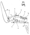
- Figur 1 -
- die schematische Teil-Seitenansicht eines Aufrichtrollstuhls in der Sitz- position;
- Figur 2 -
- die Darstellung nach
Figur 1 mit gekanteltem Sitz; - Figur 3 -
- die Darstellung nach
Figur 1 während der Aufrichtbewegung des Sitzes; - Figur 4 -
- die Darstellung nach
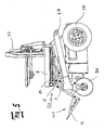
Figur 1 in der Stehposition; - Figur 5 -
- die Seitenansicht eines Aufrichtrollstuhls.
- Der Rollstuhl besteht aus dem Fahrgestell 29 mit der darauf befestigten Aufrichteeinheit 33, den Antriebsrädern 30 und den beiden lenkbaren Vorderrädern 31. Die Aufrichteeinheit 33 weist einen Sitz 2, eine Rückenlehne 32 und eine Fußauflage16 auf, die teleskopierbar in dem Führungsrohr 9 angeordnet und zusammen mit diesem eine Fußstützeneinheit 169 bildet. Über einen Aktuator 15 kann die Aufrichteeinheit 33 geschwenkt werden. Die Sitzfläche des Sitzes 2 gelangt dazu in eine vertikale Lage. Die Rückenlehne 32 behält ihre vertikale Lage bei und steht dann parallel zur Sitzfläche. Gleichzeitig mit dem Abkippen des Sitzes 2 wird die Fußauflage 16 abgesenkt. Der Schwerpunkt befindet sich in der Stehstellung zwischen den Antriebsrädern 30 und den Vorderrädern 31. Die Fußauflage ist vom Boden beabstandet, so dass es möglich ist, in der Stehstellung mit dem Rollstuhl zu fahren.
- Eine Sitzsäule 22 ist Teil des Fahrgestells und mit dem Fahrgestell 29 lösbar verbunden. Um beim Aufrichten die Absenkung der Fußstützeneinheit zu ermöglichen ist die vertikale Höhe der Sitzsäule 22 einstellbar.
- Die Anlenkung der Fußstützeneinheit 169 erfolgt über den Sitz 2. Die Verbindungslasche 1 mit den Drehachsen 4 und 5 verbindet die Sitzfläche 2 mit dem Umlenkhebel 3. Das Führungsrohr 9 in dem die Fußauflage16 mit dem Fußstützenrohr 17 teleskopierbar verbunden ist, ist über die Achse 6 drehbar mit dem Umlenkhebel 3 verbunden. Der Anschlagträger 8 ist unlösbar mit dem Führungsrohr 9 verbunden. Der Anschlag 7 ist mit dem Anschlagträger 8 lösbar verbunden. Infolge der Schwerkraft drückt das Eigengewicht der Fußstützeneinheit 169 und die Zugfeder 12 den Anschlag 7 gegen den Umlenkhebel 3. Sowohl der Anschlag 7 als auch der am Führungsrohr 9 befestigte Anschlagträger 8 ist mit einer Mehrzahl von Bohrungen 14 versehen, über die die relative Lage des Anschlags 7 zum Anschlagträger 8 eingestellt und mittels Schraubverbindung fixiert werden kann. Durch die wahlweise Befestigung des Anschlags 7 auf dem Anschlagträger 8 wird der Fußstützenwinkel γ, die Neigung der Fußstützeneinheit 169 gegenüber der Vertikalen eingestellt. Alternativ kann zur Einstellung des Fußstützenwinkels γ der Anschlagträger 8 mit dem Anschlag 7 in Längsrichtung zum Führungsrohr 9 verbunden werden. In den
Figuren 1 bis 4 ist vom Fahrgestell 29 nur die Sitzsäule 22 dargestellt. Die Verbindungslasche 1, der Umlenkhebel 3 und der Anschlagträger 8 mit dem Anschlag 7 sind links und rechts von der Sitzsäule 22 angeordnet. Es können zwei Fußstützeneinheiten 169 oder eine einzige für beide Beine vorgesehen sein. - Zur Anpassung der Unterschenkellänge des Patienten ist das Fußstützenrohr 17 teleskopisch mit dem Führungsrohr 9 verbunden. Die Fußauflage 16 ist hochklappbar um die Drehachse 19 mit dem Fußstützenrohr 17 verbunden. Sie ist im Winkel γ relativ zur Sitzsäule 22 einstellbar.
- Wie
Figur 2 zeigt, bewegt sich die Neigung (Winkel β) des Sitzes 2 ins Negative, wenn dieser gekantelt wird. Die Verbindungslasche 1 bewegt beim Kanteln den Umlenkhebel 3 und somit die gesamte Fußstützeneinheit 169. Der Fußstützenwinkel γ vergrößert sich. Gegen die Schwerkraft und die Zugfeder 12 kann der Fußstützenwinkel γ manuell bis zu einer Begrenzung vergrößert werden. Als Begrenzung für den Fußstützenwinkel γ dient die drehbar um die Achse 23 gelagerte Führungsschiene 10 mit dem darin geführten Gleitstein 18. An der Führungsschiene 10 befindet sich der Anschlagbolzen 11, der sich innerhalb des Bogensegmentes 24 bewegt. - Die aus Führungsschiene 10 und Gleitstein 18 bestehende Begrenzung kann beidseitig, einseitig oder mittig der Sitzsäule 22 angeordnet werden. Das Verbindungsblech 25 ist unlösbar mit dem Führungsrohr 9 verbunden, und der Gleitbolzen 27 mit der Achse 26 ist unlösbar mit dem Verbindungsblech 25 verbunden.
- Beim Aufrichten bewegt sich die Fußstützeneinheit 169 angetrieben durch die Schwerkraft und die Zugfeder 12 in der Führungsschiene 10 mit dem Gleitstein 18 geführt in die Vertikale. Der Winkel α der Fußauflage16 zur Horizontalen H verringert sich dabei, bis er zu Null wird. Dann erreicht die Fußstützeneinheit 169 die Vertikale und der Anschlag 7 verliert den Kontakt zum Umlenkhebel 3. Die Fußstützeneinheit 169 senkt sich nun in vertikaler Richtung bis zum Erreichen der Stehposition (
Figur 4 ) ab. Beim Erreichen der Stehposition befindet sich der Gleitbolzen 27 mit der Achse 26 unterhalb der Drehachse 23. In dieser Position ist die Fußstützeneinheit 169 fixiert. Eine Vorwärtsbewegung verhindert der Anschlagbolzen 11 im Bogensegment 24 und die Rückwärtsbewegung wird durch das von der Zugfeder 12 erzeugte Drehmoment verhindert. -
- 1
- Verbindungslaschen
- 2
- Sitz
- 3
- Umlenkhebel
- 4
- Drehachse
- 5
- Drehachse
- 6
- Achse
- 7
- Anschlag
- 8
- Anschlagträger
- 9
- Führungsrohr
- 10
- Führungsschiene
- 11
- Anschlagbolzen
- 12
- Zugfeder
- 14
- Bohrung
- 15
- Aktuator
- 16
- Fußauflage
- 17
- Fußstützenrohr
- 18
- Gleitstein
- 19
- Drehachse
- 22
- Sitzsäule
- 23
- Drehachse
- 24
- Bogensegment
- 25
- Verbindungsblech
- 26
- Achse
- 27
- Gleitbolzen
- 29
- Fahrgestell
- 30
- Hinterrad
- 31
- Vorderrad
- 32
- Rückenlehne
- 33
- Aufrichteeinheit
- 169
- Fußstützeneinheit
- α
- Winkel (Neigung der Fußauflage16 zur Horizontalen H)
- β
- Sitzwinkel
- γ
- Fußstützenwinkel
- H
- Horizontale
Claims (13)
- Aufrichtrollstuhl mit einem Fahrgestell (29, 22), einem am Fahrgestell (29, 22) schwenkbar angeordneten Sitz (2), der während einer Aufrichtbewegung von einer im Wesentlichen horizontalen Sitzposition in eine im Wesentlichen vertikale Stehposition verschwenkbar ist, und mindestens einer am Fahrgestell (29, 22) angeordneten Fußauflage (16), die in der Stehposition zum Boden hin abgesenkt ist, dadurch gekennzeichnet, dass in der Sitzposition des Sitzes (2) die Fußauflage (16) gegenüber der Horizontalen (H) im Winkel (α) geneigt ist und während der Aufrichtbewegung der Winkel (α) zu Null wird.
- Aufrichtrollstuhl nach Anspruch 1, dadurch gekennzeichnet, dass der Winkel (α) zu Beginn der Aufrichtbewegung zu Null wird.
- Aufrichtrollstuhl nach Anspruch 1 oder 2, dadurch gekennzeichnet, dass die vertikale Absenkung der Fußauflage (16) erst beginnt, wenn α=0 erreicht ist.
- Aufrichtrollstuhl nach einem oder mehreren der vorstehenden Ansprüche, dadurch gekennzeichnet, dass die Fußauflage (16) teleskopierbar in einem Führungsrohr (9) aufgenommen ist und zusammen mit diesem eine Fußstützeneinheit (169) bildet.
- Aufrichtrollstuhl nach Anspruch 4, dadurch gekennzeichnet, dass die Fußstützeneinheit (169) gelenkig an einem schwenkbar am Fahrgestell (22) angeordneten Umlenkhebel (3) befestigt ist.
- Aufrichtrollstuhl nach Anspruch 5, dadurch gekennzeichnet, dass der Umlenkhebel (3) mit dem Sitz (2) in Verbindung steht.
- Aufrichtrollstuhl nach Anspruch 6, dadurch gekennzeichnet, dass der Umlenkhebel (3) mittels einer Verbindungslasche (1) mit dem Sitz (2) in Verbindung steht und die Verbindungslasche (1) mit ihrem einen Ende (1') gelenkig am Sitz und mit ihrem anderen Ende (1 ") gelenkig am Umlenkhebel (3) befestigt ist.
- Aufrichtrollstuhl nach einem oder mehreren der vorstehenden Ansprüche, dadurch gekennzeichnet, dass der Umlenkhebel (3) federbelastet ist.
- Aufrichtrollstuhl nach einem oder mehreren der vorstehenden Ansprüche, dadurch gekennzeichnet, dass die Neigung der Fußstützeneinheit (169) gegenüber der Vertikalen im Winkel (γ) einstellbar ist.
- Aufrichtrollstuhl nach einem oder mehreren der vorstehenden Ansprüche, dadurch gekennzeichnet, dass die vertikale Absenkung der Fußauflage (16) zusammen mit der Aufrichtbewegung eingeleitet wird.
- Aufrichtrollstuhl nach einem oder mehreren der vorstehenden Ansprüche, dadurch gekennzeichnet, dass die Fußstützeneinheit (169) in der Stehposition verriegelt ist.
- Aufrichtrollstuhl nach Anspruch 4, dadurch gekennzeichnet, dass der Teil des Fahrgestells (22), an dem die Fußstützeneinheit (169) gelenkig befestigt ist, in der Höhe einstellbar ist.
- Aufrichtrollstuhl nach einem oder mehreren der vorstehenden Ansprüche, dadurch gekennzeichnet, dass der Neigungswinkel (α) der Fußauflage (16) einstellbar ist.
Applications Claiming Priority (1)
| Application Number | Priority Date | Filing Date | Title |
|---|---|---|---|
| DE102007044832A DE102007044832A1 (de) | 2007-09-18 | 2007-09-18 | Aufrichtrollstuhl |
Publications (2)
| Publication Number | Publication Date |
|---|---|
| EP2039335A1 true EP2039335A1 (de) | 2009-03-25 |
| EP2039335B1 EP2039335B1 (de) | 2011-02-16 |
Family
ID=40044089
Family Applications (1)
| Application Number | Title | Priority Date | Filing Date |
|---|---|---|---|
| EP08016103A Active EP2039335B1 (de) | 2007-09-18 | 2008-09-12 | Aufrichtrollstuhl |
Country Status (7)
| Country | Link |
|---|---|
| US (1) | US7891695B2 (de) |
| EP (1) | EP2039335B1 (de) |
| JP (1) | JP2009072591A (de) |
| CN (1) | CN101467928B (de) |
| AT (1) | ATE498383T1 (de) |
| AU (1) | AU2008217006B2 (de) |
| DE (2) | DE102007044832A1 (de) |
Cited By (3)
| Publication number | Priority date | Publication date | Assignee | Title |
|---|---|---|---|---|
| WO2011015876A3 (en) * | 2009-08-06 | 2011-04-14 | Vernacare Limited | Portering chair. |
| EP2063847A4 (de) * | 2006-09-19 | 2013-06-26 | Handicare Produksjon As | Vorrichtung und verfahren zur einstellung einer beinauflage für einen rollstuhl |
| EP3437614A4 (de) * | 2016-03-31 | 2020-04-15 | Young Bae You | Fussstützenvorrichtung und sicherheitsvorrichtung für rollstuhl |
Families Citing this family (15)
| Publication number | Priority date | Publication date | Assignee | Title |
|---|---|---|---|---|
| US8302221B1 (en) | 2009-03-03 | 2012-11-06 | Pivot Assist, Llc | Medical assist device with lift seat |
| US8596719B2 (en) * | 2010-10-01 | 2013-12-03 | Permobil Ab | Wheelchair backrest assembly |
| DE102012003763A1 (de) * | 2012-02-24 | 2013-08-29 | Volkswagen Aktiengesellschaft | Modulares karosseriefestes Unterschenkelauflageteil mit pneumatisch veränderbarer Auflagefläche |
| CN105030445A (zh) * | 2014-12-24 | 2015-11-11 | 艾玮 | 辅助起坐装置 |
| EP3251649B1 (de) * | 2015-01-29 | 2020-03-18 | France Bed Co., Ltd. | Rollstuhl |
| WO2016121158A1 (ja) * | 2015-01-29 | 2016-08-04 | フランスベッド株式会社 | 車椅子 |
| EP3243492B1 (de) * | 2016-05-09 | 2019-02-13 | 4 Power 4 | Rollstuhl zur einnahme einer aufrechten position mit rückwärtig vertikalisierendem und abwärts gerichtetem bewegungsverlauf der fussstütze |
| CN108618903A (zh) * | 2018-05-04 | 2018-10-09 | 李秀荣 | 一种医用互联网智能救护床 |
| US10792200B1 (en) | 2019-04-06 | 2020-10-06 | RapAdapt LLC | Assistive mobility device |
| US11813212B2 (en) | 2019-04-06 | 2023-11-14 | Rapadapt Corporation | Assistive mobility device |
| CN110897801A (zh) * | 2019-10-22 | 2020-03-24 | 奥佳华智能健康科技集团股份有限公司 | 助站椅 |
| NL2026723B1 (nl) * | 2020-10-21 | 2022-06-28 | Anthonius Johannes Tolboom | Zitinrichting |
| JP7750750B2 (ja) * | 2021-01-20 | 2025-10-07 | 中央発條株式会社 | 車椅子 |
| CN113520736B (zh) * | 2021-07-29 | 2024-07-30 | 四川大学华西医院 | 一种可方便站立的轮椅 |
| EP4302741B1 (de) | 2022-07-07 | 2025-01-29 | Permobil AB | Motorisierter rollstuhl mit mittelradantrieb mit standfähigkeit |
Citations (5)
| Publication number | Priority date | Publication date | Assignee | Title |
|---|---|---|---|---|
| EP0155918A2 (de) * | 1984-03-19 | 1985-09-25 | Amici Ivano | Rollstuhl für Invaliden |
| EP0155981A2 (de) | 1980-10-20 | 1985-10-02 | Hoechst-Roussel Pharmaceuticals Incorporated | Alkoxythiophenolabkömmlinge; Alkoxyphenolthiocarbamate |
| FR2697418A1 (fr) | 1992-11-05 | 1994-05-06 | Konior Mario | Assise multipositions notamment pour personnes handicapées. |
| US5356172A (en) | 1991-07-23 | 1994-10-18 | Zvi Gilad Smolinsky | Sliding seat assembly for a propelled wheel chair |
| EP0815822B1 (de) | 1996-06-27 | 1999-01-20 | Levo AG Dottikon | Aufrichtrollstuhl |
Family Cites Families (11)
| Publication number | Priority date | Publication date | Assignee | Title |
|---|---|---|---|---|
| AU430169B2 (en) * | 1968-10-11 | 1972-11-15 | Hodge Investments Proprietary Limited' | Invalid chair |
| CH608186A5 (de) * | 1976-01-30 | 1978-12-29 | Valutec Ag | |
| US4231614A (en) * | 1978-10-27 | 1980-11-04 | Shaffer Gene P | Wheelchair |
| SE438960B (sv) * | 1982-05-04 | 1985-05-28 | Permobil Ab | Fotplatteanordning for rullstol |
| CN2055033U (zh) * | 1989-02-27 | 1990-03-28 | 中国康复研究中心 | 站立轮椅 |
| AUPQ534500A0 (en) | 2000-01-31 | 2000-02-17 | Internet Development Professionals Pty Ltd. | A system for delivering educational information |
| FR2813520B1 (fr) * | 2000-09-07 | 2002-12-06 | Idc Medical | Dispositif de maintien corporel pour fauteuil verticalisateur et fauteuil en faisant application |
| DE20221016U1 (de) * | 2002-08-19 | 2004-11-25 | Nachtwey, Christian | Elektrisch betreibbares mittels Joystick steuerbares, mehrrädriges Fahrzeug für Rollstuhlfahrer |
| US6976698B2 (en) * | 2003-04-24 | 2005-12-20 | Rehabilitation Institute Of Chicago | Manually operable standing wheelchair |
| TW590768B (en) * | 2003-05-12 | 2004-06-11 | Advantek Taiwan Inc | Wheelchair structure |
| DE102005038029B3 (de) * | 2005-08-08 | 2006-11-09 | Otto Bock Healthcare Ip Gmbh & Co. Kg | Aufrichtrollstuhl |
-
2007
- 2007-09-18 DE DE102007044832A patent/DE102007044832A1/de not_active Withdrawn
-
2008
- 2008-09-12 DE DE502008002599T patent/DE502008002599D1/de active Active
- 2008-09-12 AT AT08016103T patent/ATE498383T1/de active
- 2008-09-12 EP EP08016103A patent/EP2039335B1/de active Active
- 2008-09-15 US US12/210,623 patent/US7891695B2/en not_active Expired - Fee Related
- 2008-09-15 AU AU2008217006A patent/AU2008217006B2/en not_active Ceased
- 2008-09-18 CN CN2008102470839A patent/CN101467928B/zh active Active
- 2008-09-18 JP JP2008239892A patent/JP2009072591A/ja active Pending
Patent Citations (5)
| Publication number | Priority date | Publication date | Assignee | Title |
|---|---|---|---|---|
| EP0155981A2 (de) | 1980-10-20 | 1985-10-02 | Hoechst-Roussel Pharmaceuticals Incorporated | Alkoxythiophenolabkömmlinge; Alkoxyphenolthiocarbamate |
| EP0155918A2 (de) * | 1984-03-19 | 1985-09-25 | Amici Ivano | Rollstuhl für Invaliden |
| US5356172A (en) | 1991-07-23 | 1994-10-18 | Zvi Gilad Smolinsky | Sliding seat assembly for a propelled wheel chair |
| FR2697418A1 (fr) | 1992-11-05 | 1994-05-06 | Konior Mario | Assise multipositions notamment pour personnes handicapées. |
| EP0815822B1 (de) | 1996-06-27 | 1999-01-20 | Levo AG Dottikon | Aufrichtrollstuhl |
Cited By (3)
| Publication number | Priority date | Publication date | Assignee | Title |
|---|---|---|---|---|
| EP2063847A4 (de) * | 2006-09-19 | 2013-06-26 | Handicare Produksjon As | Vorrichtung und verfahren zur einstellung einer beinauflage für einen rollstuhl |
| WO2011015876A3 (en) * | 2009-08-06 | 2011-04-14 | Vernacare Limited | Portering chair. |
| EP3437614A4 (de) * | 2016-03-31 | 2020-04-15 | Young Bae You | Fussstützenvorrichtung und sicherheitsvorrichtung für rollstuhl |
Also Published As
| Publication number | Publication date |
|---|---|
| US7891695B2 (en) | 2011-02-22 |
| DE102007044832A1 (de) | 2009-04-02 |
| ATE498383T1 (de) | 2011-03-15 |
| DE502008002599D1 (de) | 2011-03-31 |
| EP2039335B1 (de) | 2011-02-16 |
| CN101467928B (zh) | 2012-03-21 |
| CN101467928A (zh) | 2009-07-01 |
| AU2008217006B2 (en) | 2012-05-24 |
| US20090072513A1 (en) | 2009-03-19 |
| JP2009072591A (ja) | 2009-04-09 |
| AU2008217006A1 (en) | 2009-04-02 |
Similar Documents
| Publication | Publication Date | Title |
|---|---|---|
| EP2039335B1 (de) | Aufrichtrollstuhl | |
| EP2190396B1 (de) | Aufrichtrollstuhl | |
| EP1802263B1 (de) | Aufrichtrollstuhl | |
| EP2175821B1 (de) | Aufrichteinheit für aufrichtrollstühle und stühle, insbesondere therapiestühle | |
| DE69533978T2 (de) | Rollstuhl | |
| EP2758016B1 (de) | Rollstuhl mit in der höhe und neigung verstellbarem sitz | |
| EP2830565B1 (de) | Aufstehtrainer | |
| DE102005038029B3 (de) | Aufrichtrollstuhl | |
| DE60017617T2 (de) | Hebevorrichtung für Behinderte | |
| DE3333570A1 (de) | Faltbarer rollstuhl | |
| EP2258331B1 (de) | Einrichtung zum Aufrichten einer Person | |
| DE102016100661B4 (de) | Aufrichtstuhl | |
| DE4208559C1 (en) | U=shaped walking aid carriage for early mobilisation of patients with leg damage - has min. load on damaged leg achieved with pedal movable via two links and giving way under effect of adjustable step load pressure. | |
| DE202009014560U1 (de) | Toilettensitz | |
| DE102013104050B4 (de) | Sitzsystem | |
| DE19912830B4 (de) | Hebestuhl für Behinderte und Invalide | |
| DE4115385C2 (de) | ||
| DE102008027793A1 (de) | Behandlungsstuhl | |
| DE7043924U (de) | Vorrichtung zur koerperlichen schulung und zur fortbewegung von koerperbehinderten | |
| DE19546115C2 (de) | Stehtrainer | |
| DE19912840B4 (de) | Hebestuhl für Behinderte und Invalide | |
| DE102024204020A1 (de) | Stehgerät zum Stehtraining einer Person | |
| DE1183199B (de) | Krankenfahrstuhl | |
| DE1541327A1 (de) | Rollstuhl | |
| DE3019299A1 (de) | Orthopaedische selbstfahrliege |
Legal Events
| Date | Code | Title | Description |
|---|---|---|---|
| PUAI | Public reference made under article 153(3) epc to a published international application that has entered the european phase |
Free format text: ORIGINAL CODE: 0009012 |
|
| AK | Designated contracting states |
Kind code of ref document: A1 Designated state(s): AT BE BG CH CY CZ DE DK EE ES FI FR GB GR HR HU IE IS IT LI LT LU LV MC MT NL NO PL PT RO SE SI SK TR |
|
| AX | Request for extension of the european patent |
Extension state: AL BA MK RS |
|
| 17P | Request for examination filed |
Effective date: 20090922 |
|
| RAP1 | Party data changed (applicant data changed or rights of an application transferred) |
Owner name: OTTO BOCK HEALTHCARE GMBH |
|
| AKX | Designation fees paid |
Designated state(s): AT BE BG CH CY CZ DE DK EE ES FI FR GB GR HR HU IE IS IT LI LT LU LV MC MT NL NO PL PT RO SE SI SK TR |
|
| GRAP | Despatch of communication of intention to grant a patent |
Free format text: ORIGINAL CODE: EPIDOSNIGR1 |
|
| GRAS | Grant fee paid |
Free format text: ORIGINAL CODE: EPIDOSNIGR3 |
|
| GRAA | (expected) grant |
Free format text: ORIGINAL CODE: 0009210 |
|
| AK | Designated contracting states |
Kind code of ref document: B1 Designated state(s): AT BE BG CH CY CZ DE DK EE ES FI FR GB GR HR HU IE IS IT LI LT LU LV MC MT NL NO PL PT RO SE SI SK TR |
|
| REG | Reference to a national code |
Ref country code: GB Ref legal event code: FG4D Free format text: NOT ENGLISH |
|
| REG | Reference to a national code |
Ref country code: CH Ref legal event code: EP |
|
| REG | Reference to a national code |
Ref country code: IE Ref legal event code: FG4D Free format text: LANGUAGE OF EP DOCUMENT: GERMAN |
|
| REF | Corresponds to: |
Ref document number: 502008002599 Country of ref document: DE Date of ref document: 20110331 Kind code of ref document: P |
|
| REG | Reference to a national code |
Ref country code: DE Ref legal event code: R096 Ref document number: 502008002599 Country of ref document: DE Effective date: 20110331 |
|
| REG | Reference to a national code |
Ref country code: SE Ref legal event code: TRGR |
|
| REG | Reference to a national code |
Ref country code: NL Ref legal event code: T3 |
|
| LTIE | Lt: invalidation of european patent or patent extension |
Effective date: 20110216 |
|
| PG25 | Lapsed in a contracting state [announced via postgrant information from national office to epo] |
Ref country code: LT Free format text: LAPSE BECAUSE OF FAILURE TO SUBMIT A TRANSLATION OF THE DESCRIPTION OR TO PAY THE FEE WITHIN THE PRESCRIBED TIME-LIMIT Effective date: 20110216 Ref country code: HR Free format text: LAPSE BECAUSE OF FAILURE TO SUBMIT A TRANSLATION OF THE DESCRIPTION OR TO PAY THE FEE WITHIN THE PRESCRIBED TIME-LIMIT Effective date: 20110216 Ref country code: LV Free format text: LAPSE BECAUSE OF FAILURE TO SUBMIT A TRANSLATION OF THE DESCRIPTION OR TO PAY THE FEE WITHIN THE PRESCRIBED TIME-LIMIT Effective date: 20110216 Ref country code: ES Free format text: LAPSE BECAUSE OF FAILURE TO SUBMIT A TRANSLATION OF THE DESCRIPTION OR TO PAY THE FEE WITHIN THE PRESCRIBED TIME-LIMIT Effective date: 20110527 Ref country code: GR Free format text: LAPSE BECAUSE OF FAILURE TO SUBMIT A TRANSLATION OF THE DESCRIPTION OR TO PAY THE FEE WITHIN THE PRESCRIBED TIME-LIMIT Effective date: 20110517 Ref country code: PT Free format text: LAPSE BECAUSE OF FAILURE TO SUBMIT A TRANSLATION OF THE DESCRIPTION OR TO PAY THE FEE WITHIN THE PRESCRIBED TIME-LIMIT Effective date: 20110616 Ref country code: NO Free format text: LAPSE BECAUSE OF FAILURE TO SUBMIT A TRANSLATION OF THE DESCRIPTION OR TO PAY THE FEE WITHIN THE PRESCRIBED TIME-LIMIT Effective date: 20110516 |
|
| PG25 | Lapsed in a contracting state [announced via postgrant information from national office to epo] |
Ref country code: PL Free format text: LAPSE BECAUSE OF FAILURE TO SUBMIT A TRANSLATION OF THE DESCRIPTION OR TO PAY THE FEE WITHIN THE PRESCRIBED TIME-LIMIT Effective date: 20110216 Ref country code: CY Free format text: LAPSE BECAUSE OF FAILURE TO SUBMIT A TRANSLATION OF THE DESCRIPTION OR TO PAY THE FEE WITHIN THE PRESCRIBED TIME-LIMIT Effective date: 20110216 Ref country code: BG Free format text: LAPSE BECAUSE OF FAILURE TO SUBMIT A TRANSLATION OF THE DESCRIPTION OR TO PAY THE FEE WITHIN THE PRESCRIBED TIME-LIMIT Effective date: 20110516 Ref country code: SI Free format text: LAPSE BECAUSE OF FAILURE TO SUBMIT A TRANSLATION OF THE DESCRIPTION OR TO PAY THE FEE WITHIN THE PRESCRIBED TIME-LIMIT Effective date: 20110216 Ref country code: FI Free format text: LAPSE BECAUSE OF FAILURE TO SUBMIT A TRANSLATION OF THE DESCRIPTION OR TO PAY THE FEE WITHIN THE PRESCRIBED TIME-LIMIT Effective date: 20110216 |
|
| REG | Reference to a national code |
Ref country code: IE Ref legal event code: FD4D |
|
| PG25 | Lapsed in a contracting state [announced via postgrant information from national office to epo] |
Ref country code: IE Free format text: LAPSE BECAUSE OF FAILURE TO SUBMIT A TRANSLATION OF THE DESCRIPTION OR TO PAY THE FEE WITHIN THE PRESCRIBED TIME-LIMIT Effective date: 20110216 Ref country code: EE Free format text: LAPSE BECAUSE OF FAILURE TO SUBMIT A TRANSLATION OF THE DESCRIPTION OR TO PAY THE FEE WITHIN THE PRESCRIBED TIME-LIMIT Effective date: 20110216 Ref country code: DK Free format text: LAPSE BECAUSE OF FAILURE TO SUBMIT A TRANSLATION OF THE DESCRIPTION OR TO PAY THE FEE WITHIN THE PRESCRIBED TIME-LIMIT Effective date: 20110216 |
|
| PG25 | Lapsed in a contracting state [announced via postgrant information from national office to epo] |
Ref country code: RO Free format text: LAPSE BECAUSE OF FAILURE TO SUBMIT A TRANSLATION OF THE DESCRIPTION OR TO PAY THE FEE WITHIN THE PRESCRIBED TIME-LIMIT Effective date: 20110216 Ref country code: CZ Free format text: LAPSE BECAUSE OF FAILURE TO SUBMIT A TRANSLATION OF THE DESCRIPTION OR TO PAY THE FEE WITHIN THE PRESCRIBED TIME-LIMIT Effective date: 20110216 Ref country code: SK Free format text: LAPSE BECAUSE OF FAILURE TO SUBMIT A TRANSLATION OF THE DESCRIPTION OR TO PAY THE FEE WITHIN THE PRESCRIBED TIME-LIMIT Effective date: 20110216 |
|
| PLBE | No opposition filed within time limit |
Free format text: ORIGINAL CODE: 0009261 |
|
| STAA | Information on the status of an ep patent application or granted ep patent |
Free format text: STATUS: NO OPPOSITION FILED WITHIN TIME LIMIT |
|
| 26N | No opposition filed |
Effective date: 20111117 |
|
| REG | Reference to a national code |
Ref country code: DE Ref legal event code: R097 Ref document number: 502008002599 Country of ref document: DE Effective date: 20111117 |
|
| BERE | Be: lapsed |
Owner name: OTTO BOCK HEALTHCARE G.M.B.H. Effective date: 20110930 |
|
| PG25 | Lapsed in a contracting state [announced via postgrant information from national office to epo] |
Ref country code: MC Free format text: LAPSE BECAUSE OF NON-PAYMENT OF DUE FEES Effective date: 20110930 |
|
| PG25 | Lapsed in a contracting state [announced via postgrant information from national office to epo] |
Ref country code: BE Free format text: LAPSE BECAUSE OF NON-PAYMENT OF DUE FEES Effective date: 20110930 |
|
| PG25 | Lapsed in a contracting state [announced via postgrant information from national office to epo] |
Ref country code: MT Free format text: LAPSE BECAUSE OF FAILURE TO SUBMIT A TRANSLATION OF THE DESCRIPTION OR TO PAY THE FEE WITHIN THE PRESCRIBED TIME-LIMIT Effective date: 20110216 |
|
| REG | Reference to a national code |
Ref country code: CH Ref legal event code: PL |
|
| PG25 | Lapsed in a contracting state [announced via postgrant information from national office to epo] |
Ref country code: LU Free format text: LAPSE BECAUSE OF NON-PAYMENT OF DUE FEES Effective date: 20110912 |
|
| PG25 | Lapsed in a contracting state [announced via postgrant information from national office to epo] |
Ref country code: IS Free format text: LAPSE BECAUSE OF FAILURE TO SUBMIT A TRANSLATION OF THE DESCRIPTION OR TO PAY THE FEE WITHIN THE PRESCRIBED TIME-LIMIT Effective date: 20110216 Ref country code: LI Free format text: LAPSE BECAUSE OF NON-PAYMENT OF DUE FEES Effective date: 20120930 Ref country code: CH Free format text: LAPSE BECAUSE OF NON-PAYMENT OF DUE FEES Effective date: 20120930 |
|
| PG25 | Lapsed in a contracting state [announced via postgrant information from national office to epo] |
Ref country code: TR Free format text: LAPSE BECAUSE OF FAILURE TO SUBMIT A TRANSLATION OF THE DESCRIPTION OR TO PAY THE FEE WITHIN THE PRESCRIBED TIME-LIMIT Effective date: 20110216 |
|
| PG25 | Lapsed in a contracting state [announced via postgrant information from national office to epo] |
Ref country code: HU Free format text: LAPSE BECAUSE OF FAILURE TO SUBMIT A TRANSLATION OF THE DESCRIPTION OR TO PAY THE FEE WITHIN THE PRESCRIBED TIME-LIMIT Effective date: 20110216 |
|
| REG | Reference to a national code |
Ref country code: AT Ref legal event code: MM01 Ref document number: 498383 Country of ref document: AT Kind code of ref document: T Effective date: 20130912 |
|
| PG25 | Lapsed in a contracting state [announced via postgrant information from national office to epo] |
Ref country code: AT Free format text: LAPSE BECAUSE OF NON-PAYMENT OF DUE FEES Effective date: 20130912 |
|
| REG | Reference to a national code |
Ref country code: DE Ref legal event code: R082 Ref document number: 502008002599 Country of ref document: DE Representative=s name: GRAMM, LINS & PARTNER PATENT- UND RECHTSANWAEL, DE |
|
| REG | Reference to a national code |
Ref country code: FR Ref legal event code: PLFP Year of fee payment: 9 |
|
| REG | Reference to a national code |
Ref country code: FR Ref legal event code: PLFP Year of fee payment: 10 |
|
| REG | Reference to a national code |
Ref country code: DE Ref legal event code: R082 Ref document number: 502008002599 Country of ref document: DE Representative=s name: GRAMM, LINS & PARTNER PATENT- UND RECHTSANWAEL, DE Ref country code: DE Ref legal event code: R081 Ref document number: 502008002599 Country of ref document: DE Owner name: OTTOBOCK SE & CO. KGAA, DE Free format text: FORMER OWNER: OTTO BOCK HEALTHCARE GMBH, 37115 DUDERSTADT, DE |
|
| REG | Reference to a national code |
Ref country code: FR Ref legal event code: PLFP Year of fee payment: 11 |
|
| PGFP | Annual fee paid to national office [announced via postgrant information from national office to epo] |
Ref country code: SE Payment date: 20220922 Year of fee payment: 15 Ref country code: NL Payment date: 20220922 Year of fee payment: 15 Ref country code: GB Payment date: 20220927 Year of fee payment: 15 |
|
| PGFP | Annual fee paid to national office [announced via postgrant information from national office to epo] |
Ref country code: FR Payment date: 20220920 Year of fee payment: 15 |
|
| PGFP | Annual fee paid to national office [announced via postgrant information from national office to epo] |
Ref country code: IT Payment date: 20220930 Year of fee payment: 15 |
|
| REG | Reference to a national code |
Ref country code: SE Ref legal event code: EUG |
|
| REG | Reference to a national code |
Ref country code: NL Ref legal event code: MM Effective date: 20231001 |
|
| GBPC | Gb: european patent ceased through non-payment of renewal fee |
Effective date: 20230912 |
|
| PG25 | Lapsed in a contracting state [announced via postgrant information from national office to epo] |
Ref country code: NL Free format text: LAPSE BECAUSE OF NON-PAYMENT OF DUE FEES Effective date: 20231001 |
|
| PG25 | Lapsed in a contracting state [announced via postgrant information from national office to epo] |
Ref country code: NL Free format text: LAPSE BECAUSE OF NON-PAYMENT OF DUE FEES Effective date: 20231001 |
|
| PG25 | Lapsed in a contracting state [announced via postgrant information from national office to epo] |
Ref country code: GB Free format text: LAPSE BECAUSE OF NON-PAYMENT OF DUE FEES Effective date: 20230912 |
|
| PG25 | Lapsed in a contracting state [announced via postgrant information from national office to epo] |
Ref country code: GB Free format text: LAPSE BECAUSE OF NON-PAYMENT OF DUE FEES Effective date: 20230912 Ref country code: FR Free format text: LAPSE BECAUSE OF NON-PAYMENT OF DUE FEES Effective date: 20230930 |
|
| PG25 | Lapsed in a contracting state [announced via postgrant information from national office to epo] |
Ref country code: SE Free format text: LAPSE BECAUSE OF NON-PAYMENT OF DUE FEES Effective date: 20230913 |
|
| PG25 | Lapsed in a contracting state [announced via postgrant information from national office to epo] |
Ref country code: IT Free format text: LAPSE BECAUSE OF NON-PAYMENT OF DUE FEES Effective date: 20230912 |
|
| PG25 | Lapsed in a contracting state [announced via postgrant information from national office to epo] |
Ref country code: IT Free format text: LAPSE BECAUSE OF NON-PAYMENT OF DUE FEES Effective date: 20230912 |
|
| PGFP | Annual fee paid to national office [announced via postgrant information from national office to epo] |
Ref country code: DE Payment date: 20250919 Year of fee payment: 18 |