EP2036729B1 - Ensemble d'encres, ensemble de cartouches d'encre, procédé d'impression à jet d'encre, unité d'impression et appareil d'impression à jet d'encre - Google Patents
Ensemble d'encres, ensemble de cartouches d'encre, procédé d'impression à jet d'encre, unité d'impression et appareil d'impression à jet d'encre Download PDFInfo
- Publication number
- EP2036729B1 EP2036729B1 EP07767638.5A EP07767638A EP2036729B1 EP 2036729 B1 EP2036729 B1 EP 2036729B1 EP 07767638 A EP07767638 A EP 07767638A EP 2036729 B1 EP2036729 B1 EP 2036729B1
- Authority
- EP
- European Patent Office
- Prior art keywords
- ink
- inks
- specific gravity
- ejection orifice
- orifice line
- Prior art date
- Legal status (The legal status is an assumption and is not a legal conclusion. Google has not performed a legal analysis and makes no representation as to the accuracy of the status listed.)
- Active
Links
Images


Classifications
-
- B—PERFORMING OPERATIONS; TRANSPORTING
- B41—PRINTING; LINING MACHINES; TYPEWRITERS; STAMPS
- B41J—TYPEWRITERS; SELECTIVE PRINTING MECHANISMS, i.e. MECHANISMS PRINTING OTHERWISE THAN FROM A FORME; CORRECTION OF TYPOGRAPHICAL ERRORS
- B41J2/00—Typewriters or selective printing mechanisms characterised by the printing or marking process for which they are designed
- B41J2/005—Typewriters or selective printing mechanisms characterised by the printing or marking process for which they are designed characterised by bringing liquid or particles selectively into contact with a printing material
- B41J2/01—Ink jet
- B41J2/17—Ink jet characterised by ink handling
- B41J2/175—Ink supply systems ; Circuit parts therefor
- B41J2/17503—Ink cartridges
- B41J2/1752—Mounting within the printer
-
- B—PERFORMING OPERATIONS; TRANSPORTING
- B41—PRINTING; LINING MACHINES; TYPEWRITERS; STAMPS
- B41J—TYPEWRITERS; SELECTIVE PRINTING MECHANISMS, i.e. MECHANISMS PRINTING OTHERWISE THAN FROM A FORME; CORRECTION OF TYPOGRAPHICAL ERRORS
- B41J2/00—Typewriters or selective printing mechanisms characterised by the printing or marking process for which they are designed
- B41J2/005—Typewriters or selective printing mechanisms characterised by the printing or marking process for which they are designed characterised by bringing liquid or particles selectively into contact with a printing material
- B41J2/01—Ink jet
- B41J2/17—Ink jet characterised by ink handling
- B41J2/175—Ink supply systems ; Circuit parts therefor
- B41J2/17503—Ink cartridges
- B41J2/17513—Inner structure
-
- B—PERFORMING OPERATIONS; TRANSPORTING
- B41—PRINTING; LINING MACHINES; TYPEWRITERS; STAMPS
- B41J—TYPEWRITERS; SELECTIVE PRINTING MECHANISMS, i.e. MECHANISMS PRINTING OTHERWISE THAN FROM A FORME; CORRECTION OF TYPOGRAPHICAL ERRORS
- B41J2/00—Typewriters or selective printing mechanisms characterised by the printing or marking process for which they are designed
- B41J2/005—Typewriters or selective printing mechanisms characterised by the printing or marking process for which they are designed characterised by bringing liquid or particles selectively into contact with a printing material
- B41J2/01—Ink jet
- B41J2/17—Ink jet characterised by ink handling
- B41J2/175—Ink supply systems ; Circuit parts therefor
- B41J2/17503—Ink cartridges
- B41J2/17553—Outer structure
-
- B—PERFORMING OPERATIONS; TRANSPORTING
- B41—PRINTING; LINING MACHINES; TYPEWRITERS; STAMPS
- B41J—TYPEWRITERS; SELECTIVE PRINTING MECHANISMS, i.e. MECHANISMS PRINTING OTHERWISE THAN FROM A FORME; CORRECTION OF TYPOGRAPHICAL ERRORS
- B41J29/00—Details of, or accessories for, typewriters or selective printing mechanisms not otherwise provided for
- B41J29/02—Framework
-
- C—CHEMISTRY; METALLURGY
- C09—DYES; PAINTS; POLISHES; NATURAL RESINS; ADHESIVES; COMPOSITIONS NOT OTHERWISE PROVIDED FOR; APPLICATIONS OF MATERIALS NOT OTHERWISE PROVIDED FOR
- C09D—COATING COMPOSITIONS, e.g. PAINTS, VARNISHES OR LACQUERS; FILLING PASTES; CHEMICAL PAINT OR INK REMOVERS; INKS; CORRECTING FLUIDS; WOODSTAINS; PASTES OR SOLIDS FOR COLOURING OR PRINTING; USE OF MATERIALS THEREFOR
- C09D11/00—Inks
- C09D11/30—Inkjet printing inks
- C09D11/40—Ink-sets specially adapted for multi-colour inkjet printing
Definitions
- This invention relates to the use of an ink set including a plurality of inks which is stored respectively in ink cartridges having ink storage portions which is brought into a hermetically-closed state, an ink jet recording method, a recording unit and an ink jet recording apparatus.
- ink jet recording apparatuses it is required to supply ink stably from an ink cartridge to a recording head so as not to cause any leakage of the ink from the recording head or any lowering of recording performance because of excess ink supply.
- JP 2005-325298 (A ) relates to an ink jet recording device comprising an ink set composed of at least two types of ink compositions formulated at different viscosities and to the same density, ink holder members and to hold the ink compositions respectively, a temperature detecting device for detecting the environmental temperature, and a mixing means for mixing, at a proper mixing ratio, the at least two types of ink compositions contained in the ink set, based on the environmental temperature detected by the temperature detecting device.
- WO 02/066565 (A1 ) relates to a dye-based, thermal ink jet printer ink being formulated by combining a water miscible organic solvent, water, and a dye, and blending the water miscible organic solvent, the water, and the dye together.
- the ink has the ability to form printed images on a variety of textile media and can be used to achieve acceptable results on both coated silk and coated cotton substrates.
- US 2003/048336 (A1 ) relates to an ink path through which ink is delivered from an ink source to a printhead unit including an ink tube and a joint.
- EP 1044815 (A2 ) relates to a liquid storing container attachable and detachable to and from a recording device including a negative pressure producing member storage chamber made to accommodate a negative pressure producing member and equipped with a liquid supplying section and an atmosphere communication section, a liquid storage chamber having a communicating hole for establishing communication with the negative pressure producing member storage chamber and made to define a substantially hermetic space for storing a liquid to be supplied to the negative pressure producing member, a partition wall for establishing a partition between the negative pressure producing member storage chamber and the liquid storage chamber and for defining the communicating hole.
- the present inventors have studies the use of an ink cartridge having such an ink storage portion as stated below, as an ink cartridge suited for storing therein an ink containing a pigment as a coloring material (i.e., a pigment ink). Specifically, the inventors have studied the use of an ink cartridge not having any porous ink storing member. It is considered that such an ink cartridge can keep the pigment from sedimentation and that the amount of ink remaining in the ink cartridge after being used up can be reduced to an amount as small as possible. Further, the present inventors have made studies by using as an ink jet recording apparatus an ink jet recording apparatus on which the ink cartridge as stated above can be mounted in plurality.
- the present inventors have conducted a so-called cleaning operation in which, when the ink jet recording apparatus is not operated, negative pressure is produced by means of a purging pump communicating with a cap with which ejection orifice lines of the recording head are covered, to discharge any unnecessary ink from ejection orifices by purging. Thereafter, the inventors again operated the apparatus to eject an ink from the recording head. As a result, the inventors have found the following problem to come about.
- this color mixing phenomenon was a phenomenon caused by the same mechanism as in the color mixing phenomenon hitherto known in the art. More specifically, the ink adhered to the surface of the recording head or the ink present inside the cap (such ink is hereinafter referred to as "ink residue") comes into ink channels due to capillary force exerted by the ink channels, so that a different ink comes into the vicinity of ejection orifices of the ink channels. They have considered in this way.
- the present inventors have conducted operations in which the ink is ejected inside the cap before the recording is started (this operation is hereinafter referred to as "preliminary ejection"), which is conventionally conducted as a common method for avoiding the color mixing phenomenon.
- this operation is hereinafter referred to as "preliminary ejection"
- the color mixing phenomenon has by no means been resolved even when the number of ink droplets ejected in the preliminary ejection (the number of preliminary ejection droplets) is greatly increased as compared with the number of preliminary ejection droplets that is large enough to resolve the conventional color mixing phenomenon.
- the present inventors have conducted the cleaning operation several times for the purpose of discharging all the ink remaining at the part inside the ink channels where the color mixing phenomenon has occurred.
- the cleaning operation was performed many times, the color mixing phenomenon was not resolved; instead, a serious degree of the color mixing phenomenon occurred, bringing about a result contrary to their expectations.
- the present inventors have studied in detail the color mixing phenomenon. As a result, the inventors have found the following. That is, the inventors have found that this color mixing phenomenon involved in the present invention is not the color mixing phenomenon conventionally observed in the vicinity of ejection orifices of ink channels or in the vicinity of ink channels in a common liquid chamber communicating with individual ejection orifices, but a new color mixing phenomenon such that a different ink comes into the insides of ink channels.
- the "common liquid chamber” refers to a common liquid chamber communicating, in common, with a plurality of ink channels which communicate respectively with a plurality of ejection orifices in the recording head from which ink is to be ejected.
- the “insides of ink channels” refer to the whole of the ink channels and common liquid chamber of the recording head and further ink supply paths through which ink is to be fed to the common liquid chamber from the ink storage portion of the ink cartridge.
- the ink jet recording apparatus was left standing for a while after the cleaning operation has been conducted, in the state the ink is not ejected from the recording head. Thereafter, the inventors conducted again recording, where, in the beginning, the recording head ejected the ink that should originally be ejected from the ejection orifices. However, upon continuing the recording in that state for a while, an ink which is not the ink that should originally be ejected from the ejection orifices has suddenly been ejected. It has been found that such a new phenomenon has never been observed occur.
- the ink which is not the ink that should originally be ejected from the ejection orifices has been found to be the different ink stated above that has come into the insides of ink channels. Further, as the lapsed time has increased during which the recording is not performed after the cleaning operation has been conducted, a phenomenon has occurred in which a different ink that had begun to come into particular ink channels comes into the insides of the ink channels. It has been found that, when such a state is brought about, the matter is far beyond the level of a color mixing phenomenon which can be resolved by somewhat increasing the number of preliminary ejection droplets or by other adjustments.
- an object of the present invention is to provide the use of an ink set which can prevent such a new color mixing phenomenon as stated above.
- Another object of the present invention is to provide an ink jet recording method, a recording unit and an ink jet recording apparatus which use the above ink set.
- an ink set which includes a plurality of inks including a first ink and a second ink, is used in an ink injection method in which the first ink and the second ink are ejected from a recording head having a first ejection orifice line for ejecting the first ink and a second ejection orifice line for ejecting the second ink and wherein the first ejection orifice line and the second ejection orifice line are capped with the same cap, wherein the plurality of inks constituting the ink set is stored respectively in ink cartridges each having an ink storage portion which is brought into a hermetically-closed state such that the ink stored in the ink storage portion communicates with the atmosphere only through an ink supply opening, wherein the difference in specific gravity between the first ink having the largest specific gravity and the second ink having the smallest specific gravity among the plurality of ink
- the ink jet recording method is an ink jet recording method including ejecting inks by an ink jet method, wherein the method uses the above ink set, wherein the plurality of inks constituting the ink set is stored respectively in ink cartridges each having an ink storage portion which is brought into a hermetically-closed state such that the ink stored in the ink storage portion communicates with the atmosphere only through an ink supply opening and wherein the first ink and the second ink are ejected from a recording head having a first ejection orifice line for ejecting the first ink and a second ejection orifice line for ejecting the second ink and wherein the first ejection orifice line and the second ejection orifice line are capped with the same cap.
- the recording unit according to claim 8 of the present invention is a recording unit including ink cartridges each having an ink storage portion, which stores a respective ink and which is brought into a hermetically-closed state such that the ink stored in the ink storage portion communicates with the atmosphere only through an ink supply opening, and a recording head for ejecting the inks and which has a first ejection orifice line for ejecting the first ink and a second ejection orifice line for ejecting the second ink and the first ejection orifice line and the second ejection orifice line are capped with the same cap, wherein the inks are the plurality of inks that constitutes the ink set as defined above.
- the ink jet recording apparatus is an ink jet recording apparatus including ink cartridges each having an ink storage portion, which stores are respective ink and which is brought into a hermetically-closed state such that the ink stored in the ink storage portion communicates with the atmosphere only through an ink supply opening, and a recording head for ejecting inks and which has a first ejection orifice line for ejecting the first ink and a second ejection orifice line for ejecting the second ink and the first ejection orifice line and the second ejection orifice line are capped with the same cap, wherein the inks are the plurality of inks that constitutes the ink set as defined above.
- an ink set is used which can prevent the color mixing phenomenon even when ink cartridges whose ink storage portions are brought into a hermetically-closed state are used.
- good images can be provided by performing the preliminary ejection to the same degree as conventionally performed.
- an ink jet recording method, a recording unit and an ink jet recording apparatus can be provided which use the ink set.
- the specific gravities of inks, water-soluble organic solvents and coloring materials, and the viscosities and surface tensions of inks can be measured at 25°C by a conventional method.
- the specific gravities of inks, water-soluble organic solvents and coloring materials were measured at 25°C by using a float type specific gravity hydrometer (trade name: Standard Specific Gravity Hydrometer; manufactured by Tech-Jam Co., Ltd.).
- the viscosities of inks were measured at 25°C by using RE80L Type Viscometer (manufactured by Toki Sangyo Co., Ltd.).
- the surface tensions of inks were measured at 25°C by using an automatic surface tension meter CBVP-Z (manufactured by Kyowa Interface Science Co., Ltd.). Further, in the present invention, the value of difference is taken as an absolute value.
- the present inventors have conducted various studies. First, the present inventors have studied what conditions should be satisfied for causing such a color mixing phenomenon. As a result, the inventors have found that the color mixing phenomenon remarkably occurs when the following conditions are satisfied.
- the conditions are as follows: (1) among the plurality of inks in an ink jet recording apparatus, at least two types of inks ejected from the ejection orifices adjacent to each other are different in specific gravity by 0.020 or more; and (2) the at least two types of inks are stored respectively in ink cartridges whose ink storage portions storing the inks are brought into a hermetically-closed state.
- ink storage portion which is brought into a hermetically-closed state is used to mean that a state can be brought about in which, at the time of cleaning operation, there is substantially no part where the ink storage portion comes into contact with the atmosphere. Specifically, it means that the part where the ink storage portion comes into contact with the atmosphere is only an ink supply opening, namely, the ink stored in the ink storage portion communicates with the atmosphere only through an ink supply opening.
- the ink storage portion is set up in the following way.
- the ink jet recording apparatus is designed so that the ejection orifices of the recording head can be covered with a cap in order to prevent the ink from evaporating, and the cap is so set up as to communicate with a waste ink absorber through a tube. While the cleaning operation is conducted, the ejection orifices of the recording head come into touch with the cap.
- the tube communicating with the cap communicates with the waste ink absorber, but the interior of the tube is filled with the ink during the cleaning operation.
- the ink storage portion in which the part where the ink storage portion comes into contact with the atmosphere is only the ink supply opening is substantially brought into a hermetically-closed state.
- the cap is so set up as to cap by itself the plurality of ink ejection orifice lines all together to effect the cleaning operation, i.e., purging.
- the cause of occurrence of the first color mixing phenomenon upon satisfying the conditions (1) and (2) is unclear.
- the present inventors are presuming the cause to be as stated below.
- the ink communicates with the atmosphere through only the ink supply opening. While the cleaning operation is carried out in an ink jet recording apparatus on which such an ink cartridge is mounted, the ink storage portion is substantially brought into a hermetically-closed state. On the other hand, after the cleaning operation has been completed, the ink storage portion is again brought into an open state.
- the variation of negative pressure in the insides of ink channels of the recording head (such variation is hereinafter referred to as "ripple") is larger than that in an ink cartridge which is set up so that the ink storage portion is always in contact with the atmosphere, e.g., an ink cartridge having an atmosphere communication opening in addition to the ink supply opening.
- an ink cartridge having an atmosphere communication opening in addition to the ink supply opening has a ripple of about 10 mmHg.
- the ink cartridge having the ink storage portion which is brought into a hermetically-closed state has a ripple of from about 20 mmHg to about 30 mmHg.
- the present inventors presume that, because of such a large ripple, the force of drawing the ink residue into the insides of ink channels is abruptly increased, and this is one of major causes of occurrence of the first color mixing phenomenon.
- the following phenomenon has been found to occur when, among the plurality of ink cartridges mounted on an ink jet recording apparatus, an ink cartridge is present in which the quantity of ink remaining therein is extremely smaller quantity than that in other ink cartridge(s). More specifically, it has been found that the ink channels of a recording head which communicate with the ink cartridge in which the quantity of ink remaining therein is small have a larger ripple before and after the cleaning operation, than ink channels of the recording head which communicate with other ink cartridges. As a result, the ink residue is especially remarkably drawn into the insides of ink channels communicating with the ink cartridge in which the quantity of ink remaining therein is small.
- the ink residue is present in the insides of ink channels, unlike the color mixing phenomenon conventionally observed in the vicinity of ejection orifices of ink channels or in the vicinity of ink channels in a common liquid chamber communicating with individual ejection orifices (hereinafter referred to as "second color mixing phenomenon").
- second color mixing phenomenon the state of the ink residue present in ink channels immediately after the cleaning operation is considered to be substantially the same. That is, the ink residue is distributed over broader range in the insides of ink channels in the case when the first color mixing phenomenon occurs.
- the influence of the movement of a fluid due to the ripple begins to decrease, where the movement of a fluid due to the difference in specific gravity between the plurality of inks, i.e., gravity becomes predominant. More specifically, an ink having a large specific gravity and being originally present in the insides of ink channels moves to the vicinity of ejection orifices of the ink channels. An ink residue having a small specific gravity among ink residues drawn into the ink channels moves up to the insides of ink channels, in particular, the ink supply paths through which the ink is to be fed from the ink storage portion to the common liquid chamber in an ink cartridge.
- the concentration distribution of coloring materials comes to be present in the insides of ink channels of individual inks.
- the ink jet recording is left standing for a while after the cleaning operation has been conducted, in the state no ink is ejected from ejection orifices, and thereafter the recording is again performed, an ink which should be ejected from particular ejection orifices is ejected.
- an ink which should not be ejected from those ejection orifices i.e., a different ink having been drawn into the insides of the ink channels is suddenly ejected. It is presumed that such a phenomenon that has never been observed has occurred.
- the first color mixing phenomenon is quite different from the second color mixing phenomenon known conventionally.
- the present inventors have further ascertained that the first color mixing phenomenon stated above remarkably occurs when inks (pigment inks) containing pigments as coloring materials are used, as compared with inks (dye inks) containing dyes as coloring materials.
- inks pigment inks
- dye inks dyes as coloring materials.
- the present inventors presume the reason to be as stated below. That is, in the pigments, in particular, polymer dispersion type pigments described later, coloring materials themselves, i.e., the pigments or pigment dispersions themselves are more different in specific gravity than the dyes.
- the coloring materials in ink residues having come into the insides of ink channels come more deeply into the insides of the ink channels as the lapsed time is increased during which the recording is not performed, after the cleaning operation has been conducted. Such a phenomenon is presumed to be caused by the difference in specific gravity between these coloring materials.
- the present inventors have found that the problems discussed above can be resolved by allowing the properties of the plurality of inks constituting an ink set to have the following relationship. That is, it has been found that, where ink cartridges whose ink storage portions are brought into a hermetically-closed state are used as ink cartridges each of which stores each of the plurality of inks constituting an ink set, the following constitution should be satisfied.
- the difference in specific gravity between a first ink having the largest specific gravity and a second ink having the smallest specific gravity is set to be less than 0.020, whereby the first color mixing phenomenon can be prevented from occurring.
- the present inventors have made studies by using ink cartridges whose ink storage portions are so set up as to come in contact with the atmosphere, e.g., ink cartridges having atmosphere communication openings in addition to ink supply openings.
- ink cartridges having atmosphere communication openings in addition to ink supply openings.
- the following has been found. That is, a plurality of inks different in specific gravity by 0.020 or more are respectively filled respectively in the above ink cartridges, and, after the cleaning operation has been conducted, the ink jet recording apparatus is left standing for a while in the state any ink is not ejected from the ejection orifices, and thereafter the recording is performed again.
- the first color mixing phenomenon has been found not to occur.
- the ripple before and after the cleaning operation differs between the case of using the ink cartridges having atmosphere communication openings in addition to ink supply openings and the case of using the ink cartridges whose ink storage portions are brought into a hermetically-closed state.
- the ripple before and after the cleaning operation is relatively larger in the case of using the ink cartridges whose ink storage portions are brought into a hermetically-closed state.
- the movement of fluids due to the difference in specific gravity between the plurality of inks is considered to be a phenomenon that may come about without regard to the value of the ripple.
- it is considered that the movement of fluids due to the difference in specific gravity is not brought about until the rate of the movement of fluids due to a ripple having a value larger than a certain value comes to be present.
- ink cartridges whose ink storage portions are brought into a hermetically-closed state are used as ink cartridges each of which stores each of the plurality of inks constituting an ink set
- the following constitution should be satisfied in order to prevent the first color mixing phenomenon. That is, it is important that, among the plurality of inks, the difference in specific gravity between a first ink having the largest specific gravity and a second ink having the smallest specific gravity is set to be less than 0.020.
- the difference in specific gravity between the first ink and the second ink is set to be 0.0030 or more. In the present invention, it is more preferable that the difference in specific gravity between the first ink and the second ink is set to be 0.0030 or more and less than 0.020.
- the present inventors have conceived the idea that the specific gravities of the plurality of inks constituting an ink set is rendered as uniform as possible.
- the inventors have found that the first color mixing phenomenon can be resolved by setting the difference in specific gravity between a first ink having the largest specific gravity and a second ink having the smallest specific gravity among the plurality of inks constituting an ink set to be less than 0.020.
- the inventors have accomplished the present invention.
- the first ink and the second ink each have a specific gravity of 1.030 or more, the first color mixing phenomenon can be more effectively prevented from occurring. If the first ink and the second ink each have a specific gravity of less than 1.030, the movement rate of fluids due to the fact that the ripple before and after the cleaning operation is increased when ink residues are drawn into the insides of ink channels. As a result, the ink residues drawn into the insides of ink channels come to easily move into the insides of ink channels.
- the first ink and the second ink each have a specific gravity of 1.100 or less.
- the first ink and the second ink each have a specific gravity of 1.030 or more and 1.100 or less, and more preferably 1.041 or more and 1.093 or less, because the effect of preventing the color mixing phenomenon can more effectively be achieved.
- all the inks constituting an ink set each have a specific gravity of 1.030 or more and 1.100 or less, and more preferably from 1.041 or more to 1.093 or less.
- the specific gravities of coloring materials contained respectively in the plurality of inks constituting an ink satisfy the following relationship. That is, it is preferable that the difference in specific gravity between a first coloring material having the largest specific gravity and a second coloring material having the smallest specific gravity among a coloring material contained in the first ink and a coloring material contained in the second ink, is set to be 0.020 or less.
- the present inventors have studied the relationship between the specific gravities of coloring materials and the color mixing phenomenon in the case where organic pigments are used as coloring materials.
- the inventors have compared a color mixing phenomenon of C.I. Pigment Green 7 having a relatively large specific gravity and C.I. Pigment Red 122 having an average specific gravity, with a color mixing phenomenon of C.I. Pigment Blue 15:3 having a somewhat large specific gravity and C.I. Pigment Red 122.
- the second color mixing phenomenon can be prevented in a smaller number of preliminary ejection droplets.
- the first coloring material and the second coloring material are different in specific gravity by 0.010 or less.
- the "coloring material” in the present invention refers to a pigment. Further, in the present invention, with the coloring material being a pigment, the coloring material also refers to a pigment dispersion containing the pigment and a dispersing agent.
- the "specific gravity of coloring material” in the present invention refers to the specific gravity of a liquid in which all the components other than the coloring material (in a case where the coloring material is a pigment, the pigment dispersion containing the pigment and a dispersing agent) and water in an ink have been replaced by water.
- the content of the coloring material in each of the first ink and second ink is set as in the following. That is, it is preferable that the content of the first coloring material is equal to the content of the second coloring material or that the content of the first coloring material is smaller than the content of the second coloring material. This is because setting the content of coloring materials in this way makes it difficult to bring about the color mixing phenomenon due to the difference in specific gravity between coloring materials. This phenomenon appears as a more remarkable difference when the coloring material in each of the first ink and second ink has a specific gravity of 1.017 or more and 1.039 or less.
- a water-soluble organic solvent having the smallest specific gravity is defined as a first water-soluble organic solvent.
- the first water-soluble organic solvent and the first coloring material are different in specific gravity by 0.049 or less. This is because the coloring material can be prevented from moving when an ink jet recording apparatus is left standing for a long time in the state that inks are present in the insides of ink channels.
- the flow channel resistance in recording head through which the first ink is ejected is made larger than the flow channel resistance in recording head through which the second ink is ejected.
- the viscosity of ink may be controlled to properly adjust the flow channel resistance in the recording head.
- the viscosity of the first ink may be made larger than the viscosity of the second ink, whereby the flow channel resistance in recording head through which the first ink is ejected can be made larger than the flow channel resistance in recording head through which the second ink is ejected.
- the difference in viscosity between the first ink and the second ink may somewhat differ depending on how ink channels are set up.
- the viscosity of the first ink may preferably be made larger by 10% or more, and more preferably 15% or more, than the viscosity of the second ink.
- the first ink and the second ink each preferably have a viscosity of 2.0 mPa ⁇ s or more and 5.0 mPa ⁇ s or less. It is particularly preferable that all the inks constituting an ink set each have a viscosity of 2.0 mPa ⁇ s or more and 5.0 mPa ⁇ s or less.
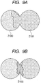
- FIGS. 9A and 9B are diagrammatic views showing how two types of liquids behave when they come into contact with each other.
- the first pattern is such that, as shown in FIG. 9A , one liquid (liquid 2: Z1001) spreads one-sidedly into the other liquid (liquid 1: Z1000).
- the second pattern is such that, as shown in FIG. 9B , liquids act to mutually diffuse into each other, and hence, become in a state of liquid (Z1002) in which these liquids are mixed at the boundary part where they come in contact with each other.
- an ink set is set up so that among the plurality of inks constituting the ink set, the surface tension of the first ink having the largest specific gravity is made smaller than the surface tension of the second ink having the smallest specific gravity. Setting up the ink set in this way, the inventors have made studies with such expectation that an ink residue is pulled toward ink channels through which the first ink is to be ejected.
- the first color mixing phenomenon can be prevented in a smaller number of preliminary ejection droplets in the case where the surface tension of the first ink is smaller than the surface tension of the second.
- the surface tension of the first ink is made smaller than the surface tension of the second ink. Further, it is preferable that the surface tension of the second ink is larger by 3 mN/m or more than the surface tension of the first ink. It has been found that when employing such a constitution, the reliability of ejection stability and storage stability can be achievable at high levels and the first color mixing phenomenon can be more effectively prevented.
- the first ink and the second ink may each preferably have a surface tension of 25.0 mN/m or more and 50.0 mN/m or less, and more preferably 25.0 mN/m or more and 45 mN/m or less. All the inks constituting an ink set preferably have a surface tension of 25.0 mN/m or more and 50.0 mN/m or less, and more preferably from 25.0 mN/m or more to 45 mN/m or less.
- the specific gravities, viscosities and surface tensions of inks can be controlled by properly determining the types and contents of components constituting the inks.
- the specific gravities, viscosities and surface tensions of the inks can be controlled by properly determining the types and contents of polymers.
- the inks constituting an ink set it is preferable to use water and an aqueous medium containing water and a water-soluble organic solvent.
- the content (% by mass) of the water-soluble organic solvent in each ink may preferably be 3.0% by mass or more and 50.0% by mass or less based on the total mass of the ink.
- the content (% by mass) of water in each ink may preferably be 50.0% by mass or more and 95.0% by mass or less based on the total mass of the ink.
- the water-soluble organic solvent the following may be used. Specifically, it is preferable to use the following: alkyl alcohols having 1 to 6 carbon atoms such as methanol, ethanol, propanol, propanediol, butanol, butanediol, pentanol, pentanediol, hexanol and hexanediol; amides such as dimethylformamide and diethylacetamide; ketones or ketoalcohols such as acetone and diacetone alcohol; ethers such as tetrahydrofuran and dioxane; polyalkylene glycols such as polyethylene glycol and polypropylene glycol, having an average molecular weight of 200, 300, 400, 600 or 1,000; alkylene glycols whose alkylene groups have 2 to 6 carbon atoms, such as ethylene glycol, propylene glycol, butylene glycol, triethylene glycol, 1,2,6-hexanetriol,
- deionized water ion-exchange water
- any pigment materials used in conventional inks may be used.
- pigments having an anionic group may be used.
- the following may be used: pigments of a polymer dispersion type (polymer dispersion type pigments) in which a dispersing agent is used to disperse a pigment, and pigments of a self-dispersion type (self-dispersion type pigments) in which hydrophilic groups have been introduced into the pigment particle surface portions.
- pigments in which organic groups containing a high polymer are chemically bonded to the pigment particle surfaces (polymer-bonded self-dispersion type pigments), and microcapsule type pigments in which the dispersibility of the pigment itself is improved so as to be made dispersible without use of any dispersing agent.
- the content (% by mass) of the pigment in the ink may preferably be 0.1% by mass or more and 15.0% by mass or less, and more preferably 1.0% by mass or more and 10.0% by mass or less, based on the total mass of the ink.
- a black ink it is preferable to use carbon black such as furnace black, lamp black, acetylene black or channel black.
- carbon black such as furnace black, lamp black, acetylene black or channel black.
- the following commercially available products may be used, for example: RAVEN 7000, RAVEN 5750, RAVEN 5250, RAVEN 5000 ULTRA, RAVEN 3500, RAVEN 2000, RAVEN 1500, RAVEN 1250, RAVEN 1200, RAVEN 1190 ULTRA-II, RAVEN 1170, and RAVEN 1255 (which are available from Columbian Carbon Japan Limited); BLACK PEARLS L, REGAL 330R, REGAL 400R, REGAL 660R, MOGUL L, MONARCH 700, MONARCH 800, MONARCH 880, MONARCH 900, MONARCH 1000, MONARCH 1100, MONARCH 1300, MONARCH 1400, MONARCH 2000, and VALCAN X
- carbon black prepared newly for the present invention may be used.
- examples are by no means limited to these, and any conventionally known carbon black may be used.
- carbon black not only carbon black, but also fine magnetic-material particles of magnetite, ferrite or the like, and titanium black may also be used.
- the organic pigment the following may be used, for example: water-insoluble azo pigments such as Toluidine Red, Toluidine maroon, Hanza Yellow, Benzidine Yellow and Pyrazolone Red; water-soluble azo pigments such as Lithol Red, Helio Bordeaux, Pigment Scarlet and Permanent Red 2B; derivatives from vat dyes, such as alizarin, indanthrone and Thioindigo maroon; phthalocyanine type pigments such as Phthalocyanine Blue and Phthalocyanine Green; quinacridone type pigments such as Quinacridone Red and Quinacridone Magenta; perylene type pigments such as Perylene Red and Perylene Scarlet; isoindolinone type pigments such as Isoindolinone Yellow and Isoindolinone Orange; imidazolone type pigments such as Benzimidazolone Yellow, Benzimidazolone Orange and Benzimidazolone Red; pyranthrone type pigments such as Pyr
- C.I. Color Index Number
- the following may be used, for example: C.I. Pigment Yellow 12, 13, 14, 17, 20, 24, 74, 83, 86, 93, 97, 109, 110, 117, 120, 125, 128, 137, 138, 147, 148, 150, 151, 153, 154, 166, 168, 180, 185; C.I. Pigment Orange 16, 36, 43, 51, 55, 59, 61, 71; C.I.
- examples are by no means limited to these.
- any water-soluble polymers may be used. Of these, it is particularly preferable to use a dispersing agent having a weight average molecular weight of 1,000 or more and 30,000 or less, and more preferably 3,000 or more and 15,000 or less.
- the content (% by mass) of the dispersing agent in the ink may preferably be 0.1% by mass or more and 5.0% by mass or less based on the total mass of the ink.
- the dispersing agent the following may be used, for example: Polymers formed from monomers such as styrene, vinyl naphthalene, aliphatic alcohol esters of ⁇ , ⁇ -ethylenically unsaturated carboxylic acids, acrylic acid, maleic acid, itaconic acid, fumaric acid, vinyl acetate, vinyl pyrrolidone, acrylamide, and derivatives thereof. At least one of monomers constituting the polymer may preferably be a hydrophilic monomer. Block copolymers, random copolymers, graft copolymers or salts thereof may be used. Natural polymers such as rosin, shellac and starch may also be used. It is preferable that these polymers are soluble in an aqueous solution in which a base has been dissolved, i.e., are of an alkali-soluble type.
- the inks constituting an ink set may each contain a moisture-retentive solid component such as urea, a urea derivative, trimethylolpropane or trimethylolethane in order to maintain moisture retention.
- the content (% by mass) of the moisture-retentive solid component in the ink may be preferably 0.1% by mass or more and 20.0% by mass or less, and more preferably 3.0% by mass or more and 10.0% by mass or less, based on the total mass of the ink.
- each of the inks constituting an ink set may use a surfactant such as an anionic surfactant, a nonionic surfactant or an amphoteric surfactant.
- a surfactant such as an anionic surfactant, a nonionic surfactant or an amphoteric surfactant.
- the following may be used: polyoxyethylene alkyl ethers, polyoxyethylene alkyl phenols, acetylene glycol compounds, and acetylene glycol ethylene oxide adducts.
- each of the inks constituting an ink set may optionally contain various additives such as a pH adjuster, an antirust, an antiseptic agent, a mildew-proofing agent, an antioxidant, a reduction-preventive agent and an evaporation accelerator.
- various additives such as a pH adjuster, an antirust, an antiseptic agent, a mildew-proofing agent, an antioxidant, a reduction-preventive agent and an evaporation accelerator.
- the ink set or the ink cartridge set according to the present invention may have any form cited below, as long as it uses a plurality of inks in combination.
- an ink set or an ink cartridge set may be cited which is constituted of ink cartridges, or ink cartridges with a recording head, having a structure in which ink storage portions each of which stores each of a cyan ink, a magenta ink, a yellow ink and a black ink are integrally provided.
- An ink set or an ink cartridge set may also be cited which is constituted of ink cartridges, or ink cartridges with a recording head, having a structure in which ink storage portions storing each of a cyan ink, a magenta ink and a yellow ink is integrally provided.
- An ink set or an ink cartridge set may further be cited in which each of separate ink cartridges storing each of such inks as above is detachably attached to an ink jet recording apparatus.
- the present invention specifies the properties of an ink itself relative to other ink used in combination in an ink jet recording apparatus or as ink cartridges, and may have any modified form without being limited to the forms cited above.
- the plurality of inks constituting the ink set according to the present invention is particularly preferably used in an ink jet recording method in which the inks are ejected by ink jet method.
- the ink-jet recording method includes, e.g., a recording method in which mechanical energy is allowed to act on an ink to eject the ink, and a recording method in which thermal energy is allowed to act on an ink to eject the ink.
- the recording method using thermal energy is preferably used in the present invention.
- Ink cartridges suitable for recording performed using the plurality of inks constituting the ink set according to the present invention include ink cartridges having ink storage portions for storing these inks. Each ink cartridge is set up as described below.
- FIG. 8 is an exploded perspective view of an ink cartridge.
- an ink cartridge 100 has a casing member constituted of a housing 1 and a cover member 2, and an upward protrudent sheet 3 bonded to the housing 1 and provided with folded parts. These form an ink storage portion.
- the ink storage portion is provided therein with a pressure plate 4 and a compressed coil spring 5 which put the pressure plate 4 toward the upward protrudent sheet side.
- the upward protrudent sheet 3 is pressed outward to produce negative pressure in the ink storage portion.
- the housing 1 is provided on one side thereof with an ink supply opening 6 coming in contact with ink channels extending to a recording head (not shown).
- the housing 1 constitutes a container storing therein the ink as described above.
- the upward protrudent sheet 3 is welded to the outer periphery of the housing 1.
- the cover member 2 is attached to the open top of the housing 1 to protect the upward protrudent sheet 3 which protrudes outward.
- a recording unit suitable for recording performed using the plurality of inks constituting the ink set according to the present invention includes a recording unit having (i) the ink cartridges having ink storage portions for storing these inks and (ii) a recording head.
- a recording unit in which the inks are ejected from the recording head by the action of heat energy.
- An ink jet recording apparatus of the present invention is characterized by having ink cartridges having ink storage portions each of which stores each of the plurality of inks constituting the ink set of the present invention and a recording head which ejects the inks.
- ink cartridges having ink storage portions each of which stores each of the plurality of inks constituting the ink set of the present invention and a recording head which ejects the inks.
- a remarkable effect can be exhibited particularly in the case of an ink jet recording apparatus whose recording head ejects the inks by applying heat energy to the inks.
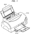
- the schematic construction of the structural mechanical part of an ink jet recording apparatus is described below.
- the ink jet recording apparatus is composed, according to the function of each mechanism, of a sheet feed part, a sheet transport part, a carriage part, a sheet delivery part, a cleaning part, and an exterior housing which protects these and provides design quality. These are schematically described below.
- FIG. 1 is a perspective view of the ink jet recording apparatus.
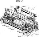
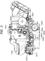
- FIGS. 2 and 3 are views to illustrate the internal structure of the ink jet recording apparatus.
- FIGS. 2 and 3 are a perspective view as viewed form the upper right and a sectional side view of the ink jet recording apparatus, respectively.
- the predetermined number of sheets of recording mediums are sent to a nip zone formed from a sheet feed roller M2080 and a separation roller M2041 (see FIGS. 1 and 3 ).
- the recording mediums thus sent are separated at the nip zone, and only the uppermost recording medium is transported.
- the recording medium sent to the sheet transport part is guided by a pinch roller holder M3000 and a sheet guide flapper M3030, and is sent to a pair of rollers, a transport roller M3060 and a pinch roller M3070.
- the pair of rollers consisting of the transport roller M3060 and the pinch roller M3070 is rotated by an LF motor E0002, and the recording medium is transported over a platen M3040 by this rotation (for the above, see FIGS. 2 and 3 ).
- a recording head H1001 (see FIG. 4 ) is set at the intended image forming position, and ejects inks against the recording medium in accordance with signals sent from an electric circuit board E0014 (see FIG. 2 ).
- the detailed construction of the recording head H1001 will be described later. Recording is performed by the recording head H1001, during which it repeats alternately the primary scanning in which scanning is carried out with a carriage M4000 (see FIG. 2 ) in the column direction and the secondary scanning in which the transport roller M3060 (see FIGS. 2 and 3 ) transports the recording medium in the line direction, whereby images are formed on the recording medium.
- this recording medium is inserted into a nip between a first sheet delivery roller M3110 and a spur M3120 at the sheet delivery part (see FIG. 3 ), is transported therethrough, and is delivered to a sheet delivery tray M3160 (see FIG. 1 ).
- FIG. 7 is a diagrammatic view showing the construction of the cleaning part of the ink jet recording apparatus.
- a pump M5000 is operated in the state a cap M5010 is brought into contact with a face having ink ejection orifices (an ejection orifice face) of the recording head H1001, whereupon inks are purged from the recording head H1001 to conduct cleaning operation for the recording head H1001 (see FIG. 4 ).
- a cap holder M5060 is moved upward by an up and down movable mechanism, and the cap M5010 is brought into contact with the ejection orifice face of the recording head H1001 at appropriate close-contact force to perform capping.
- the pump M5000 is operated in the state the capping has been performed, whereupon negative pressure is produced between the ejection orifice face and the pump M5000, so that inks are purged from respective ejection orifices constituting ejection orifice lines.
- an ejection orifice line which ejects the first ink and an ejection orifice line which ejects the second ink are capped with the same cap.
- the ejection orifice lines are hermetically-closed with purging chambers M5020 and M5030.
- the purging chambers M5020 and M5030 are provided with ink discharge openings M5070 and M5080, respectively.
- the purging chamber M5020 is provided with the ink discharge opening M5070; and the purging chamber M5030, with the ink discharge opening M5080.
- Tubes M5090 and M5100 are connected to these ink discharge openings M5070 and M5080, respectively. Further, the tubes M5090 and M5100 are connected to the pump M5000.
- the cap holder M5060 holds the cap M5010 and is driven in the direction where the cap M5010 is brought into contact with, or separated from, the ejection orifice face of the recording head H1001 by means of a drive mechanism (not shown).
- FIG. 7 construction is shown in which a purging chamber formed of a peripheral wall M5040 is partitioned with a partition wall M5050 into two purging chambers having an equal volume. These purging chambers may be different in volume from each other. Further, the purging chamber may be single. The purging chamber(s) may also be provided therein with an ink absorber.
- the construction of a head cartridge H1000 will be described (see FIG. 4 ).
- the head cartridge H1000 has the recording head H1001, a means for mounting ink cartridges denoted collectively as H1900, and a means for supplying inks from the ink cartridges H1900 to the recording head.
- the head cartridge H1000 is detachably mounted to the carriage M4000 (see FIG. 2 ).
- FIG. 4 illustrates how the ink cartridges H1900 are attached to the head cartridge H1000.
- the ink jet recording apparatus forms images using, e.g., yellow, magenta, cyan, black, light magenta, light cyan and green inks.
- the ink cartridges H1900 as well are each independently prepared for seven colors.
- each ink cartridge is detachably set in the head cartridge H1000.
- the ink cartridges H1900 may be attached or detached in the state the head cartridge H1000 is mounted on the carriage M4000 (see FIG. 2 ).
- FIG. 5 is an exploded perspective view of the head cartridge H1000.
- the head cartridge H1000 is constituted of a recording element board, a plate, an electric wiring circuit board H1300, an ink cartridge holder H1500, an ink channel forming member H1600, filters H1700, seal rubbers H1800, etc.
- the recording element board is constituted of a first recording element board 1100 and a second recording element board 1101.
- the plate is constituted of a first plate H1200 and a second plate H1400.
- the first recording element board 1100 and the second recording element board 1101 are each a silicon board, on one side of which a plurality of recording elements (nozzles) for ejecting inks are formed by photolithography. Al electric wiring through which electric power is supplied to each recording element is formed by a film-forming technique. A plurality of ink channels corresponding to the individual recording elements are also formed by photolithography. Further, ink supply openings for supplying inks to the ink channels are so formed as to be open on the back.
- FIG. 6 is an enlarged front view to illustrate the construction of the first recording element board H1100 and second recording element board H1101.
- Reference characters H2000 to H2600 denote lines of recording elements (hereinafter referred to also as “ejection orifice line(s)") which supply different inks, respectively.
- ejection orifice lines for three colors are formed which are a yellow ink ejection orifice line H2000, a magenta ink ejection orifice line H2100 and a cyan ink ejection orifice line H2200.
- ejection orifice lines for four colors are formed which are a light-cyan ink ejection orifice line H2300, a black ink ejection orifice line H2400, a green ink ejection orifice line H2500 and a light-magenta ink ejection orifice line H2600.
- Each ejection orifice line is constituted of a plurality of nozzles arranged at predetermined intervals in the transport direction of the recording medium. Openings of the nozzles, i.e., the ejection orifices are formed in the direction of gravity.
- FIG. 6 shows an illustration in which part of the nozzles constituting the ejection orifice lines are omitted.
- the head cartridge H1000 is described below with reference to FIGS. 5 and 6 .
- the first recording element board H1100 and the second recording element board H1101 are attached and fixed to the first plate H1200 by bonding.
- an ink supply opening H1201 is formed through which the ink is to be fed to the first recording element board H1100 and second recording element board H1101.
- the second plate H1400 having openings is attached and fixed to the first plate H1200.
- This second plate H1400 holds the electric wiring circuit board H1300 so that the electric wiring circuit board H1300 may be electrically connected with the first recording element board H1100 and second recording element board H1101.
- Electric signals are applied to the electric wiring circuit board H1300 applies for ejecting the inks from the respective nozzles formed on the first recording element board H1100 and second recording element board H1101.
- This electric wiring circuit board H1300 has electric wiring corresponding to the first recording element board H1100 and second recording element board H1101, and an external signal input terminal H1301 which is positioned at an end portion of this electric wiring and receives the electric signals from the ink jet recording apparatus.
- the external signal input terminal H1301 is located and fastened on the back side of the ink cartridge holder H1500.
- the channel forming member H1600 is fastened by, e.g., ultrasonic welding to form ink channels H1501 which connects the ink cartridges H1900 to the first plate H1200.
- the filters H1700 are provided so that any dust and dirt can be prevented from entering from the outside.
- the seal rubbers H1800 are also fitted at the part where the ink channels H1501 engage with the ink cartridges H1900 so that the inks can be prevented from evaporating through the part of engagement.
- the ink cartridge holder part is joined to the recording head H1001 by bonding to set up the head cartridge H1000 as mentioned above.
- the ink cartridge holder part is constituted of the ink cartridge holder H1500, the channel forming member H1600, the filters H1700 and the seal rubbers H1800.
- the recording head H1001 is constituted of the first recording element board H1100, the second recording element board H1101, the first plate H1200, the electric wiring circuit board H1300 and the second plate H1400.
- Pigment Dispersions 1 to 4 were prepared by the procedure shown below.
- the "specific gravity of coloring material” refers to the specific gravity of a liquid in which all the components other than the coloring material (the pigment dispersion containing a pigment and a dispersing agent) and water in an ink have been replaced by water.
- the specific gravity of coloring material was measured at 25°C by using a float type specific gravity hydrometer (trade name: Standard Specific Gravity Hydrometer; manufactured by Tech-Jam Co., Ltd.).
- Pigment Dispersion 1 containing C.I. Pigment Red 122 8 parts of a pigment (C.I. Pigment Red 122), 2.8 parts of a dispersing agent and 89.2 parts of ion-exchange water were mixed, followed by dispersion for 3 hours by means of a batch type vertical sand mill. Thereafter, the fluid dispersion obtained was treated by centrifugation to remove coarse particles, followed by pressure filtration using a micro-filter of 3.0 ⁇ m in pore size (available from Fuji Photo Film Co., Ltd.) to prepare Pigment Dispersion 1 having a pigment concentration of 8% by mass.
- a polymer was used which was obtained by neutralizing poly(benzyl methacrylate-co-acrylic acid) (compositional molar ratio: 70:30) having an acid value of 200 and a weight average molecular weight of 12,000, with a 10% by mass potassium hydroxide aqueous solution.
- Pigment Dispersion 2 containing C.I. Pigment Red 149 8 parts of a pigment (C.I. Pigment Red 149), 5.6 parts of a dispersing agent and 86.4 parts of ion-exchange water were mixed, followed by dispersion for 3 hours by means of a batch type vertical sand mill. Thereafter, the fluid dispersion obtained was treated by centrifugation to remove coarse particles, followed by pressure filtration using a micro-filter of 3.0 ⁇ m in pore size (available from Fuji Photo Film Co., Ltd.) to prepare Pigment Dispersion 2 having a pigment concentration of 8% by mass.
- a polymer was used which was obtained by neutralizing a styrene-acrylic acid copolymer having an acid value of 200 and a weight average molecular weight of 10,000, with a 10% by mass sodium hydroxide aqueous solution.
- Pigment Dispersion 3 containing C.I. Pigment Green 7 8 parts of a pigment (C.I. Pigment Green 7), 4.8 parts of a dispersing agent and 87.2 parts of ion-exchange water were mixed, followed by dispersion for 3 hours by means of a batch type vertical sand mill. Thereafter, the fluid dispersion obtained was treated by centrifugation to remove coarse particles, followed by pressure filtration using a micro-filter of 3.0 ⁇ m in pore size (available from Fuji Photo Film Co., Ltd.) to prepare Pigment Dispersion 3 having a pigment concentration of 8% by mass.
- a polymer was used which was obtained by neutralizing a benzyl methacrylate-acrylic acid AB type block copolymer having an acid value of 250 and a weight average molecular weight of 5,000, with a 10% by mass potassium hydroxide aqueous solution.
- Pigment Dispersion 4 containing C.I. Pigment Blue 15:3: 8 parts of a pigment (C.I. Pigment Blue 15:3), 8 parts of a dispersing agent and 84 parts of ion-exchange water were mixed, followed by dispersion for 3 hours by means of a batch type vertical sand mill. Thereafter, the fluid dispersion obtained was treated by centrifugation to remove coarse particles, followed by pressure filtration using a micro-filter of 3.0 ⁇ m in pore size (available from Fuji Photo Film Co., Ltd.) to prepare Pigment Dispersion 4 having a pigment concentration of 8% by mass.
- a polymer was used which was obtained by neutralizing poly(benzyl methacrylate-co-acrylic acid) (compositional molar ratio: 70:30) having an acid value of 200 and a weight average molecular weight of 12,000, with a 10% by mass sodium hydroxide aqueous solution.
- Table 1 The components shown in the following Table 1 were mixed, and stirred thoroughly, followed by pressure filtration using a micro-filter of 3.0 ⁇ m in pore size (available from Fuji Photo Film Co., Ltd.) to prepare Inks 1 to 12.
- Table 1 the values of specific gravity of each ink and each coloring material and the values of viscosity and surface tension of each ink are shown.
- the specific gravity was measured at 25°C by using a float type specific gravity hydrometer (trade name: Standard Specific Gravity Hydrometer; manufactured by Tech-Jam Co., Ltd.).
- the viscosity is measured at 25°C by using RE80L Type Viscometer (manufactured by Toki Sangyo Co., Ltd.).
- the surface tension is measured at 25°C by using an automatic surface tension meter CBVP-Z (manufactured by Kyowa Interface Science Co., Ltd.).
- the pigment concentrations of Inks 1-7 and 9-12 and Ink 8 are 4% by mass and 5% by mass, respectively.
- the specific gravity of each of the water-soluble organic solvents used in the preparation of the inks is shown in Table 2 below.
- the specific gravity was measured at 25°C by using a float type specific gravity hydrometer (trade name: Standard Specific Gravity Hydrometer; manufactured by Tech-Jam Co., Ltd.).
- the inks obtained as described above were used in such combinations as shown in the upper column of Table 3 shown below, to make up ink sets of Examples 1 to 9 and Comparative Examples 1 to 3.
- the inks constituting the respective ink sets were each filled into the ink cartridge constructed as shown in FIG. 8 .
- the ink cartridge constructed as shown in FIG. 8 has the ink storage portion which is brought into a hermetically-closed state, i.e., has the ink storage portion in which the ink comes into contact with the atmosphere only through the ink supply opening.
- the inks were filled into the ink cartridges, the inks were filled in the following quantities based on the maximum quantity in which each ink could be filled into the ink cartridge.
- the first ink was filled in a half quantity based on the maximum fill of the ink cartridge, and the second ink was filled in the maximum quantity in the ink cartridge.
- the fill of each of the inks constituting the ink set were set as above so that the differences of the ripples in the recording head were more easily brought about.
- various values of the inks constituting the ink set are shown together.
- ink jet recording apparatus (trade name: PIXUS 990i; manufactured by CANON INC.) whose recording head the inks were to be ejected from by the action of thermal energy.
- This ink jet recording apparatus was one which performed recording in one pass and one direction, in which the number of ejection orifices forming the ejection orifice lines of the recording head was 768 for each color, the width between the respective ejection orifice lines was 0.64 inches, and the ejection volume per ink droplet was about 2 pL (picoliters).
- the ink cartridges were mounted to the ink jet recording apparatus in such a manner that the ink cartridge storing the first ink was at the position of yellow and the ink cartridge storing the second ink was at the position of magenta, thus the ejection orifice lines of the inks constituting the ink set were adjacent to each other.
- the ink jet recording apparatus was one in which the ejection orifice lines for yellow and magenta were capped with the same cap, thereby performing cleaning operation.
- Professional Photopaper PR-101 (available from CANON INC.) was used as the recording medium.
- the steps of preparing two sheets of recorded matter, performing the cleaning operation, stopping the recording for a predetermined period of time and preparing one sheet of recorded matter were repeated twice in the same way as in the above except that the time periods for which the recording was stopped after the cleaning operation had been performed was made was changed to 30 minutes and 60 minutes, respectively.
- Evaluation was made by visually observing the color mixing state on the sheets of recorded matter obtained after the recording was stopped for the predetermined time periods (10 minutes, 30 minutes and 60 minutes). Evaluation criteria of color mixing are as shown below. The evaluation results are shown in Table 4.
- Example 1 As a result of the evaluation made on the color mixing according to the criteria shown above, entirely the same results were obtained in Examples 1, 3 and 5 to 8.
- Example 3 the color mixing state in the images formed after the recording was stopped for 30 minutes was slightly inferior to that in Examples 1, 5, 6 and 8.
- Example 3 the color mixing state in the images formed after the recording was stopped for 60 minutes was the same as the color mixing state in the images formed after the recording was stopped for 30 minutes.
- Example 1, 5 and 6 the color mixing state in the images formed after the recording was stopped for 30 minutes was slightly superior to that in Example 3, but the color mixing in the images formed after the recording was stopped for 60 minutes was at the same level.
- Example 8 when the color mixing state in the images formed after the recording was stopped for 60 minutes was compared between Examples 5 and 8, the color mixing state in Example 8 was slightly inferior to that in Example 5. Similarly, when the color mixing state in the images formed after the recording was stopped for 60 minutes was compared between Examples 5 and 7, the color mixing state in Example 7 was slightly inferior to that in Example 5.
Landscapes
- Chemical & Material Sciences (AREA)
- Life Sciences & Earth Sciences (AREA)
- Engineering & Computer Science (AREA)
- Materials Engineering (AREA)
- Wood Science & Technology (AREA)
- Organic Chemistry (AREA)
- Inks, Pencil-Leads, Or Crayons (AREA)
- Ink Jet Recording Methods And Recording Media Thereof (AREA)
- Ink Jet (AREA)
Claims (9)
- Utilisation d'un ensemble d'encres comportant une pluralité d'encres comprenant une première encre et une seconde encre pour un procédé d'éjection d'encre dans lequel la première encre et la seconde encre sont éjectées depuis une tête d'enregistrement comportant une première ligne d'orifices d'éjection destinée à éjecter la première encre et une seconde ligne d'orifices d'éjection destinée à éjecter la seconde encre, et la première ligne d'orifices d'éjection et la seconde ligne d'orifices d'éjection étant fermées par le même capuchon,
dans laquelle la pluralité d'encres constituant l'ensemble d'encres est contenue respectivement dans des cartouches d'encre comportant individuellement une partie de stockage d'encre qui est amenée dans un état de fermeture hermétique de sorte que l'encre contenue dans la partie de stockage d'encre ne communique avec l'atmosphère que par l'intermédiaire d'une ouverture d'alimentation en encre,
dans laquelle la différence de gravité spécifique, déterminée conformément à la description, entre la première encre ayant la gravité spécifique la plus grande et la seconde encre ayant la gravité spécifique la plus petite parmi la pluralité d'encres constituant l'ensemble d'encres est inférieure à 0,020, et
dans laquelle les matériaux colorants contenus dans la pluralité d'encres sont des pigments. - Utilisation selon la revendication 1, dans laquelle, entre un matériau colorant contenu dans la première encre et un matériau colorant contenu dans la seconde encre, une différence de gravité spécifique, déterminée conformément à la description, entre un premier matériau colorant ayant la gravité spécifique la plus grande et un second matériau colorant ayant la gravité spécifique la plus petite est inférieure ou égale à 0,010.
- Utilisation selon la revendication 1 ou 2, dans laquelle, entre un solvant organique soluble dans l'eau contenu dans la première encre et un solvant organique soluble dans l'eau contenu dans la seconde encre, une différence de gravité spécifique, déterminée conformément à la description, entre le premier solvant organique soluble dans l'eau ayant la gravité spécifique la plus petite et le premier matériau colorant est inférieure ou égale à 0,049.
- Utilisation selon l'une quelconque des revendications 1 à 3, dans laquelle la viscosité de la première encre est supérieure à la viscosité de la seconde encre, la viscosité étant déterminée conformément à la description.
- Utilisation selon l'une quelconque des revendications 1 à 4, dans laquelle la tension superficielle de la première encre est inférieure à la tension superficielle de la seconde encre, la tension superficielle étant déterminée conformément à la description.
- Utilisation selon l'une quelconque des revendications 1 à 5, dans laquelle la tension superficielle de la seconde encre est supérieure d'une valeur supérieure ou égale à 3 mN/m à la tension superficielle de la première encre, la tension superficielle étant déterminée conformément à la description.
- Procédé d'enregistrement par jet d'encre consistant à éjecter des encres par un procédé de jet d'encre, le procédé utilisant l'ensemble d'encres selon l'une quelconque des revendications 1 à 6, dans lequel la pluralité d'encres constituant l'ensemble d'encres est contenue respectivement dans des cartouches d'encre comportant individuellement une partie de stockage d'encre qui est amenée dans un état de fermeture hermétique de sorte que l'encre contenue dans la partie de stockage d'encre ne communique avec l'atmosphère que par l'intermédiaire d'une ouverture d'alimentation en encre, et dans lequel la première encre et la seconde encre sont éjectées depuis une tête d'enregistrement comportant une première ligne d'orifices d'éjection destinée à éjecter la première encre et une seconde ligne d'orifices d'éjection destinée à éjecter la seconde encre, et dans lequel la première ligne d'orifices d'éjection et la seconde ligne d'orifices d'éjection sont fermées par le même capuchon.
- Unité d'enregistrement comprenant des cartouches d'encre comportant individuellement une partie de stockage d'encre, qui contient une encre respective et qui est amenée dans un état de fermeture hermétique de sorte que l'encre contenue dans la partie de stockage d'encre ne communique avec l'atmosphère que par l'intermédiaire d'une ouverture d'alimentation en encre, et une tête d'enregistrement destinée à éjecter les encres et comportant une première ligne d'orifices d'éjection destinée à éjecter la première encre et une seconde ligne d'orifices d'éjection destinée à éjecter la seconde encre, et la première ligne d'orifices d'éjection et la seconde ligne d'orifices d'éjection sont fermées par le même capuchon, dans laquelle les encres sont la pluralité d'encres qui constitue l'ensemble d'encres selon l'une quelconque des revendications 1 à 6.
- Appareil d'enregistrement à jet d'encre comprenant des cartouches d'encre comportant individuellement une partie de stockage d'encre, qui contient une encre respective et qui est amenée dans un état de fermeture hermétique de sorte que l'encre contenue dans la partie de stockage d'encre ne communique avec l'atmosphère que par l'intermédiaire d'une ouverture d'alimentation en encre, et une tête d'enregistrement destinée à éjecter les encres et comportant une première ligne d'orifices d'éjection destinée à éjecter la première encre et une seconde ligne d'orifices d'éjection destinée à éjecter la seconde encre, et la première ligne d'orifices d'éjection et la seconde ligne d'orifices d'éjection sont fermées par le même capuchon, dans lequel les encres sont la pluralité d'encres qui constitue l'ensemble d'encres selon l'une quelconque des revendications 1 à 6.
Applications Claiming Priority (2)
| Application Number | Priority Date | Filing Date | Title |
|---|---|---|---|
| JP2006172714 | 2006-06-22 | ||
| PCT/JP2007/062832 WO2007148824A1 (fr) | 2006-06-22 | 2007-06-20 | Ensemble d'encres, ensemble de cartouches d'encre, procédé d'impression à jet d'encre, unité d'impression et appareil d'impression à jet d'encre |
Publications (3)
| Publication Number | Publication Date |
|---|---|
| EP2036729A1 EP2036729A1 (fr) | 2009-03-18 |
| EP2036729A4 EP2036729A4 (fr) | 2014-01-22 |
| EP2036729B1 true EP2036729B1 (fr) | 2018-10-17 |
Family
ID=38833557
Family Applications (1)
| Application Number | Title | Priority Date | Filing Date |
|---|---|---|---|
| EP07767638.5A Active EP2036729B1 (fr) | 2006-06-22 | 2007-06-20 | Ensemble d'encres, ensemble de cartouches d'encre, procédé d'impression à jet d'encre, unité d'impression et appareil d'impression à jet d'encre |
Country Status (4)
| Country | Link |
|---|---|
| US (1) | US7883199B2 (fr) |
| EP (1) | EP2036729B1 (fr) |
| CN (1) | CN101370665B (fr) |
| WO (1) | WO2007148824A1 (fr) |
Families Citing this family (24)
| Publication number | Priority date | Publication date | Assignee | Title |
|---|---|---|---|---|
| CN101193989B (zh) * | 2005-06-10 | 2012-01-04 | 佳能株式会社 | 喷墨墨、生产喷墨墨的方法、喷墨记录方法、墨盒以及青色墨 |
| WO2007148824A1 (fr) | 2006-06-22 | 2007-12-27 | Canon Kabushiki Kaisha | Ensemble d'encres, ensemble de cartouches d'encre, procédé d'impression à jet d'encre, unité d'impression et appareil d'impression à jet d'encre |
| JP5578772B2 (ja) * | 2007-05-25 | 2014-08-27 | キヤノン株式会社 | インクジェット用インク、インクジェット記録方法、インクカートリッジ及びインクジェット記録装置 |
| JP5995396B2 (ja) * | 2008-08-08 | 2016-09-21 | キヤノン株式会社 | インクセット、インクジェット記録方法、及びインクジェット記録装置 |
| JP5852301B2 (ja) * | 2009-07-02 | 2016-02-03 | キヤノン株式会社 | クリアインク、インクジェット記録方法、インクセット、インクカートリッジ、記録ユニット、及びインクジェット記録装置 |
| US8362108B2 (en) | 2010-04-28 | 2013-01-29 | Canon Kabushiki Kaisha | Transfer ink jet recording aqueous ink |
| JP5911215B2 (ja) | 2010-08-03 | 2016-04-27 | キヤノン株式会社 | インク、インクカートリッジ、インクジェット記録方法、及びインクジェット記録装置 |
| JP5911211B2 (ja) | 2010-08-03 | 2016-04-27 | キヤノン株式会社 | インク、インクカートリッジ、及びインクジェット記録方法 |
| JP6039213B2 (ja) | 2011-04-19 | 2016-12-07 | キヤノン株式会社 | インク、インクカートリッジ及びインクジェット記録方法 |
| CN103289474B (zh) * | 2012-02-22 | 2016-07-06 | 精工爱普生株式会社 | 喷墨用油墨组和清洗方法 |
| US8986435B2 (en) | 2012-04-13 | 2015-03-24 | Canon Kabushiki Kaisha | Ink, ink cartridge and ink jet recording method |
| JP6161434B2 (ja) | 2012-08-09 | 2017-07-12 | キヤノン株式会社 | インク、インクカートリッジ、及びインクジェット記録方法 |
| JP6210778B2 (ja) | 2012-09-05 | 2017-10-11 | キヤノン株式会社 | インク、インクカートリッジ、及びインクジェット記録方法 |
| JP2014162819A (ja) * | 2013-02-22 | 2014-09-08 | Seiko Epson Corp | インクジェット用インクセット、及び記録装置 |
| JP2015028137A (ja) | 2013-06-26 | 2015-02-12 | キヤノン株式会社 | インク、インクカートリッジ、及びインクジェット記録方法 |
| JP6604812B2 (ja) | 2014-11-28 | 2019-11-13 | キヤノン株式会社 | 水性インクセット、インクジェット記録方法、及びインクジェット記録装置 |
| US9624395B2 (en) | 2015-01-08 | 2017-04-18 | Canon Kabushiki Kaisha | Image recording method, ink, and liquid composition |
| EP3385343B1 (fr) | 2015-01-08 | 2021-03-10 | Canon Kabushiki Kaisha | Procédé d'enregistrement d'image, encre et composition liquide |
| US9783694B2 (en) | 2015-02-10 | 2017-10-10 | Canon Kabushiki Kaisha | Image recording method and liquid set used for the method |
| US10017656B2 (en) | 2015-05-18 | 2018-07-10 | Canon Kabushiki Kaisha | Image recording method, treatment liquid and ink set |
| JP6833475B2 (ja) | 2015-12-28 | 2021-02-24 | キヤノン株式会社 | インク、インクカートリッジ、及びインクジェット記録方法 |
| JP5996136B1 (ja) * | 2016-03-04 | 2016-09-21 | 理想科学工業株式会社 | 油性インクジェットインクセット |
| US10125284B2 (en) | 2016-05-20 | 2018-11-13 | Canon Kabushiki Kaisha | Aqueous ink, ink cartridge, and ink jet recording method |
| JP7352127B2 (ja) * | 2019-01-17 | 2023-09-28 | ブラザー工業株式会社 | システム |
Family Cites Families (44)
| Publication number | Priority date | Publication date | Assignee | Title |
|---|---|---|---|---|
| JPS63118260A (ja) | 1987-10-09 | 1988-05-23 | Seiko Epson Corp | インクジェットプリンタ |
| US4794409A (en) | 1987-12-03 | 1988-12-27 | Hewlett-Packard Company | Ink jet pen having improved ink storage and distribution capabilities |
| JP3155871B2 (ja) * | 1992-10-30 | 2001-04-16 | キヤノン株式会社 | インクジェット記録装置 |
| JP3224643B2 (ja) | 1993-08-31 | 2001-11-05 | キヤノン株式会社 | インクジェットカートリッジ |
| US5790157A (en) * | 1993-08-31 | 1998-08-04 | Canon Kabushiki Kaisha | Ink filling method and apparatus for ink cartridge |
| JP3466800B2 (ja) * | 1995-11-30 | 2003-11-17 | キヤノン株式会社 | インクジェット用インク、インクジェット記録方法及びインクジェット機器 |
| JP3554110B2 (ja) * | 1996-06-28 | 2004-08-18 | キヤノン株式会社 | インクジェット記録装置 |
| US5833743A (en) * | 1996-09-10 | 1998-11-10 | Colorspan Corporation | Method of selecting an ink set of an ink jet printer |
| JP3880151B2 (ja) * | 1996-10-11 | 2007-02-14 | キヤノン株式会社 | 水溶性付加重合体、それを用いた水系インク、該水系インクを用いたインクジェット記録方法及びインクジェット捺染方法 |
| JP3745161B2 (ja) * | 1999-04-15 | 2006-02-15 | キヤノン株式会社 | 液体収納容器 |
| US6676254B2 (en) * | 2000-12-21 | 2004-01-13 | Canon Kabushiki Kaisha | Recording method, ink cartridge, printing device and information recording apparatus |
| JP2006172714A (ja) | 2000-12-28 | 2006-06-29 | Victor Co Of Japan Ltd | 情報記録担体、その再生装置及びその記録装置 |
| US6698876B2 (en) * | 2001-01-31 | 2004-03-02 | Canon Kabushiki Kaisha | Aqueous fluorescent ink, recording unit, ink cartridge, ink jet recording apparatus, and ink jet recording method |
| JP2002234183A (ja) | 2001-02-13 | 2002-08-20 | Seiko Epson Corp | インクパックおよびこれを備えたインク供給装置 |
| WO2002066565A1 (fr) * | 2001-02-16 | 2002-08-29 | Macdermid Colorspan, Inc. | Encres a colorant direct et procede de fabrication correspondant |
| US6886926B2 (en) * | 2001-09-11 | 2005-05-03 | Brother Kogyo Kabushiki Kaisha | Ink-jet printer with ink path and method of forming the ink path |
| US6854836B2 (en) * | 2001-10-05 | 2005-02-15 | Canon Kabushiki Kaisha | Liquid container, liquid supply system, liquid using apparatus, ink tank, ink supply system, inkjet print head and print apparatus |
| JP2003251821A (ja) | 2001-10-05 | 2003-09-09 | Canon Inc | 液体収納容器、液体供給システム、液体使用装置、インクタンク、インク供給システム、インクジェット記録ヘッド及び記録装置 |
| JP2003191489A (ja) | 2001-12-27 | 2003-07-08 | Canon Inc | 液体収納容器 |
| US6932465B2 (en) * | 2002-09-17 | 2005-08-23 | Canon Kabushiki Kaisha | Reaction solution, set of reaction solution and ink, ink jet recording apparatus and image recording method |
| JP4343632B2 (ja) * | 2002-09-17 | 2009-10-14 | キヤノン株式会社 | 反応液、反応液とインクとのセット、インクジェット記録装置及び画像記録方法 |
| AU2003264466A1 (en) * | 2002-09-17 | 2004-04-08 | Canon Kabushiki Kaisha | Ink set, method of forming image and water base ink for use therein |
| DE602004026799D1 (de) * | 2003-03-05 | 2010-06-10 | Seiko Epson Corp | Verfahren zur Herstellung eines Flüssigkeitsbehälters |
| CA2523885C (fr) * | 2003-05-02 | 2009-09-22 | Canon Kabushiki Kaisha | Encre fluorescente aqueuse, image enregistree y faisant appel et methode d'appreciation |
| US7431956B2 (en) * | 2003-06-20 | 2008-10-07 | Sensient Imaging Technologies, Inc. | Food grade colored fluids for printing on edible substrates |
| CN1890330B (zh) * | 2003-12-11 | 2011-01-12 | 佳能株式会社 | 水性油墨和使用它的墨盒、喷墨记录方法和记录品 |
| US7195340B2 (en) * | 2003-12-26 | 2007-03-27 | Canon Kabushiki Kaisha | Ink-jet recording method and ink-jet ink |
| JP4856885B2 (ja) * | 2004-03-16 | 2012-01-18 | キヤノン株式会社 | 液体組成物、液体組成物とインクのセット及び画像記録方法 |
| JP4981260B2 (ja) * | 2004-03-16 | 2012-07-18 | キヤノン株式会社 | 水性インク、反応液と水性インクのセット及び画像形成方法 |
| JP3958325B2 (ja) * | 2004-03-16 | 2007-08-15 | キヤノン株式会社 | プリント媒体用塗布液、インクジェット用インク、画像形成方法、プリント媒体用塗布液とインクジェット用インクとのセット、及びインクジェット記録装置 |
| JP2005325298A (ja) * | 2004-05-17 | 2005-11-24 | Seiko Epson Corp | インクジェット記録用インクセット及びインクジェット記録装置 |
| CN1972809B (zh) * | 2004-06-28 | 2011-09-07 | 佳能株式会社 | 记录方法、墨盒及图像形成方法 |
| DE602005024397D1 (de) * | 2004-06-28 | 2010-12-09 | Canon Kk | Wässrige tinte, wässriger tintensatz, tintenpatrone, tintenstrahlaufzeichner, tintenstrahlaufzeichnungsverfahren und bilderzeugungsverfahren |
| BRPI0511981B1 (pt) * | 2004-06-28 | 2020-11-03 | Canon Kabushiki Kaisha | tinta aquosa, método de formação de imagem, cartucho de tinta, unidade de gravação e aparelho de gravação de jato de tinta |
| CA2565704C (fr) * | 2004-06-28 | 2009-08-04 | Canon Kabushiki Kaisha | Encre aqueuse, systeme d'encre et procede de formation d'image |
| CN103965689B (zh) * | 2005-01-18 | 2017-04-12 | 佳能株式会社 | 墨、成套墨、喷墨记录方法、墨盒和喷墨记录设备 |
| JP2006225637A (ja) * | 2005-01-18 | 2006-08-31 | Canon Inc | インク、インクセット、インクジェット記録方法、インクカートリッジ及びインクジェット記録装置 |
| US20080032011A1 (en) * | 2005-07-01 | 2008-02-07 | Sensient Colors Inc. | Flavored and Edible Colored Fluids for Printing on Edible Substrates and Precision Deposition Thereof |
| EP1780247B1 (fr) * | 2005-10-28 | 2011-04-06 | Canon Kabushiki Kaisha | Encre aqueuse, méthode d'enregistrement par jet d'encre, réservoir d'encre, unité d'enregistrement et appareil d'enregistrement par jet d'encre |
| EP1780246B1 (fr) * | 2005-10-28 | 2009-12-16 | Canon Kabushiki Kaisha | Encre aqueuse, procédé d' enregistrement par jet d' encre, cartouche d' encre, unite d' enregistrement et appareil d' enregistrement par jet d' encre |
| DE602006013566D1 (de) * | 2005-10-28 | 2010-05-27 | Canon Kk | Wässrige Tinte, Tintenstrahlaufzeichnungsverfahren, Tintenpatrone, Aufzeichnungseinheit und Tintenstrahlaufzeichnungsgerät |
| US7705071B2 (en) * | 2006-02-15 | 2010-04-27 | Canon Kabushiki Kaisha | Aqueous ink, ink-jet recording method, ink cartridge, recording unit and ink jet recording apparatus |
| JP2007331308A (ja) * | 2006-06-16 | 2007-12-27 | Canon Inc | インクジェット記録装置およびインクジェット記録方法 |
| WO2007148824A1 (fr) | 2006-06-22 | 2007-12-27 | Canon Kabushiki Kaisha | Ensemble d'encres, ensemble de cartouches d'encre, procédé d'impression à jet d'encre, unité d'impression et appareil d'impression à jet d'encre |
-
2007
- 2007-06-20 WO PCT/JP2007/062832 patent/WO2007148824A1/fr active Application Filing
- 2007-06-20 EP EP07767638.5A patent/EP2036729B1/fr active Active
- 2007-06-20 CN CN2007800029455A patent/CN101370665B/zh active Active
- 2007-09-24 US US11/860,160 patent/US7883199B2/en active Active
Non-Patent Citations (1)
| Title |
|---|
| None * |
Also Published As
| Publication number | Publication date |
|---|---|
| EP2036729A4 (fr) | 2014-01-22 |
| EP2036729A1 (fr) | 2009-03-18 |
| US20080252708A1 (en) | 2008-10-16 |
| CN101370665A (zh) | 2009-02-18 |
| US7883199B2 (en) | 2011-02-08 |
| WO2007148824A1 (fr) | 2007-12-27 |
| CN101370665B (zh) | 2010-11-03 |
Similar Documents
| Publication | Publication Date | Title |
|---|---|---|
| EP2036729B1 (fr) | Ensemble d'encres, ensemble de cartouches d'encre, procédé d'impression à jet d'encre, unité d'impression et appareil d'impression à jet d'encre | |
| EP1918109B1 (fr) | Unité d'enregistrement, enregistreur à jet d'encre et procédé d'enregistrement à jet d'encre | |
| EP1820828B1 (fr) | Encre aqueuse, procédé d'enregistrement par jet d'encre, cartouche d'encre, unité d'enregistrement et appareil d'enregistrement par jet d'encre | |
| EP2103660B1 (fr) | Encre pour impression à jet d'encre, méthode d'impression à jet d'encre, cartouche d'encre, unité d'impression et appareil pour impression à jet d'encre | |
| US7160376B2 (en) | Aqueous ink, and ink-jet recording method, ink-jet recording apparatus, and image forming method using the same | |
| EP1995287B1 (fr) | Jeu d'encre, procédé d'enregistrement par jet d'encre, cartouche d'encre, unité d'enregistrement et appareil d'enregistrement par jet d'encre | |
| EP1748059B1 (fr) | Jeu d'encre, procédé d'enregistrement a jet d'encre, cartouche d'encre, unite d'enregistrement, appareil d'enregistrement a jet d'encre, et procede de formation d'image | |
| EP1990383B1 (fr) | Jeu d'encre, procédé d'enregistrement par jet d'encre, cartouche d'encre, unité d'enregistrement et appareil d'enregistrement par jet d'encre | |
| US8217097B2 (en) | Aqueous ink, ink jet recording method, ink cartridge, recording unit and ink jet recording apparatus | |
| US6733120B2 (en) | Ink set for ink-jet recording, recording method, ink cartridge, recording unit, and ink-jet recording apparatus | |
| JP4273104B2 (ja) | 水性インク、インクジェット記録方法、インクカートリッジ、記録ユニット、インクジェット記録方法及び画像形成方法 | |
| JP4182135B2 (ja) | 記録ユニット、インクジェット記録装置、及びインクセット | |
| JP2008260172A (ja) | インクジェット記録装置および該装置のメンテナンス方法 | |
| JP4182134B2 (ja) | インクセット、インクカートリッジのセット、記録ユニット、及びインクジェット記録装置 | |
| JP2008001801A (ja) | インクセット、インクジェット記録方法、記録ユニット、及びインクジェット記録装置 | |
| JP2009035629A (ja) | インクジェット用インク、インクジェット記録方法、インクカートリッジ、記録ユニット、及びインクジェット記録装置 | |
| JP5241110B2 (ja) | 水性インク、インクジェット記録方法、インクカートリッジ、記録ユニット、及びインクジェット記録装置 | |
| JP2008001800A (ja) | インクセット、インクジェット記録方法、記録ユニット、及びインクジェット記録装置 | |
| JP2009091492A (ja) | インクセット、インクジェット記録方法、インクカートリッジ、記録ユニット、及びインクジェット記録装置 | |
| JP2004352981A (ja) | 水性インク、インクジェット記録方法、インクカートリッジ、記録ユニット、インクジェット記録装置及び画像形成方法 | |
| JP2009091491A (ja) | インクセット、インクジェット記録方法、インクカートリッジ、記録ユニット、インクジェット記録装置、及びインク |
Legal Events
| Date | Code | Title | Description |
|---|---|---|---|
| PUAI | Public reference made under article 153(3) epc to a published international application that has entered the european phase |
Free format text: ORIGINAL CODE: 0009012 |
|
| 17P | Request for examination filed |
Effective date: 20090122 |
|
| AK | Designated contracting states |
Kind code of ref document: A1 Designated state(s): AT BE BG CH CY CZ DE DK EE ES FI FR GB GR HU IE IS IT LI LT LU LV MC MT NL PL PT RO SE SI SK TR |
|
| AX | Request for extension of the european patent |
Extension state: AL BA HR MK RS |
|
| RBV | Designated contracting states (corrected) |
Designated state(s): DE FR GB IT |
|
| DAX | Request for extension of the european patent (deleted) | ||
| RIC1 | Information provided on ipc code assigned before grant |
Ipc: B41J 29/02 20060101ALI20131129BHEP Ipc: B41J 2/01 20060101ALI20131129BHEP Ipc: C09D 11/00 20060101ALI20131129BHEP Ipc: B41J 2/175 20060101AFI20131129BHEP Ipc: B41M 5/00 20060101ALI20131129BHEP |
|
| A4 | Supplementary search report drawn up and despatched |
Effective date: 20140107 |
|
| RIC1 | Information provided on ipc code assigned before grant |
Ipc: B41J 2/175 20060101AFI20131219BHEP Ipc: B41J 2/01 20060101ALI20131219BHEP Ipc: B41J 29/02 20060101ALI20131219BHEP Ipc: B41M 5/00 20060101ALI20131219BHEP Ipc: C09D 11/00 20060101ALI20131219BHEP |
|
| 17Q | First examination report despatched |
Effective date: 20170221 |
|
| RIC1 | Information provided on ipc code assigned before grant |
Ipc: B41J 2/175 20060101AFI20180314BHEP Ipc: B41M 5/00 20060101ALI20180314BHEP Ipc: B41J 29/02 20060101ALI20180314BHEP Ipc: C09D 11/40 20140101ALI20180314BHEP Ipc: B41J 2/01 20060101ALI20180314BHEP |
|
| GRAJ | Information related to disapproval of communication of intention to grant by the applicant or resumption of examination proceedings by the epo deleted |
Free format text: ORIGINAL CODE: EPIDOSDIGR1 |
|
| GRAP | Despatch of communication of intention to grant a patent |
Free format text: ORIGINAL CODE: EPIDOSNIGR1 |
|
| INTG | Intention to grant announced |
Effective date: 20180508 |
|
| RIN1 | Information on inventor provided before grant (corrected) |
Inventor name: IMAI, TAKASHI Inventor name: HAKAMADA, SHINICHI Inventor name: IWATA, TETSU Inventor name: FUJIOKA, FUMIAKI |
|
| GRAS | Grant fee paid |
Free format text: ORIGINAL CODE: EPIDOSNIGR3 |
|
| GRAA | (expected) grant |
Free format text: ORIGINAL CODE: 0009210 |
|
| AK | Designated contracting states |
Kind code of ref document: B1 Designated state(s): DE FR GB IT |
|
| REG | Reference to a national code |
Ref country code: GB Ref legal event code: FG4D |
|
| REG | Reference to a national code |
Ref country code: DE Ref legal event code: R096 Ref document number: 602007056519 Country of ref document: DE |
|
| REG | Reference to a national code |
Ref country code: DE Ref legal event code: R097 Ref document number: 602007056519 Country of ref document: DE |
|
| PLBE | No opposition filed within time limit |
Free format text: ORIGINAL CODE: 0009261 |
|
| STAA | Information on the status of an ep patent application or granted ep patent |
Free format text: STATUS: NO OPPOSITION FILED WITHIN TIME LIMIT |
|
| 26N | No opposition filed |
Effective date: 20190718 |
|
| PGFP | Annual fee paid to national office [announced via postgrant information from national office to epo] |
Ref country code: FR Payment date: 20200626 Year of fee payment: 14 |
|
| PGFP | Annual fee paid to national office [announced via postgrant information from national office to epo] |
Ref country code: IT Payment date: 20200618 Year of fee payment: 14 |
|
| PG25 | Lapsed in a contracting state [announced via postgrant information from national office to epo] |
Ref country code: FR Free format text: LAPSE BECAUSE OF NON-PAYMENT OF DUE FEES Effective date: 20210630 |
|
| PG25 | Lapsed in a contracting state [announced via postgrant information from national office to epo] |
Ref country code: IT Free format text: LAPSE BECAUSE OF NON-PAYMENT OF DUE FEES Effective date: 20210620 |
|
| PGFP | Annual fee paid to national office [announced via postgrant information from national office to epo] |
Ref country code: DE Payment date: 20230523 Year of fee payment: 17 |
|
| PGFP | Annual fee paid to national office [announced via postgrant information from national office to epo] |
Ref country code: GB Payment date: 20230523 Year of fee payment: 17 |