EP2036609A1 - Structure en nid d'abeilles et procédé pour sa fabrication - Google Patents
Structure en nid d'abeilles et procédé pour sa fabrication Download PDFInfo
- Publication number
- EP2036609A1 EP2036609A1 EP07767832A EP07767832A EP2036609A1 EP 2036609 A1 EP2036609 A1 EP 2036609A1 EP 07767832 A EP07767832 A EP 07767832A EP 07767832 A EP07767832 A EP 07767832A EP 2036609 A1 EP2036609 A1 EP 2036609A1
- Authority
- EP
- European Patent Office
- Prior art keywords
- honeycomb
- formed body
- axial direction
- honeycomb structure
- honeycomb formed
- Prior art date
- Legal status (The legal status is an assumption and is not a legal conclusion. Google has not performed a legal analysis and makes no representation as to the accuracy of the status listed.)
- Granted
Links
- 238000004519 manufacturing process Methods 0.000 title claims description 54
- 230000002093 peripheral effect Effects 0.000 claims abstract description 106
- 238000005192 partition Methods 0.000 claims abstract description 32
- 239000012530 fluid Substances 0.000 claims abstract description 11
- 238000000034 method Methods 0.000 claims description 46
- 239000000463 material Substances 0.000 claims description 40
- 239000011248 coating agent Substances 0.000 claims description 38
- 238000000576 coating method Methods 0.000 claims description 38
- 238000000227 grinding Methods 0.000 claims description 33
- 230000000994 depressogenic effect Effects 0.000 claims description 14
- 238000003754 machining Methods 0.000 claims description 4
- 229910052751 metal Inorganic materials 0.000 abstract description 23
- 239000002184 metal Substances 0.000 abstract description 23
- 230000002401 inhibitory effect Effects 0.000 abstract description 3
- 239000004575 stone Substances 0.000 description 21
- 238000001035 drying Methods 0.000 description 17
- 239000000919 ceramic Substances 0.000 description 10
- 239000004927 clay Substances 0.000 description 6
- 238000009924 canning Methods 0.000 description 5
- 239000002994 raw material Substances 0.000 description 5
- 238000002485 combustion reaction Methods 0.000 description 4
- 230000000052 comparative effect Effects 0.000 description 4
- 238000010304 firing Methods 0.000 description 4
- 238000004901 spalling Methods 0.000 description 4
- VYPSYNLAJGMNEJ-UHFFFAOYSA-N Silicium dioxide Chemical compound O=[Si]=O VYPSYNLAJGMNEJ-UHFFFAOYSA-N 0.000 description 3
- 229910052878 cordierite Inorganic materials 0.000 description 3
- 238000005520 cutting process Methods 0.000 description 3
- JSKIRARMQDRGJZ-UHFFFAOYSA-N dimagnesium dioxido-bis[(1-oxido-3-oxo-2,4,6,8,9-pentaoxa-1,3-disila-5,7-dialuminabicyclo[3.3.1]nonan-7-yl)oxy]silane Chemical compound [Mg++].[Mg++].[O-][Si]([O-])(O[Al]1O[Al]2O[Si](=O)O[Si]([O-])(O1)O2)O[Al]1O[Al]2O[Si](=O)O[Si]([O-])(O1)O2 JSKIRARMQDRGJZ-UHFFFAOYSA-N 0.000 description 3
- 238000001125 extrusion Methods 0.000 description 3
- 238000010438 heat treatment Methods 0.000 description 3
- 238000007602 hot air drying Methods 0.000 description 3
- 238000004898 kneading Methods 0.000 description 3
- GWEVSGVZZGPLCZ-UHFFFAOYSA-N Titan oxide Chemical compound O=[Ti]=O GWEVSGVZZGPLCZ-UHFFFAOYSA-N 0.000 description 2
- MCMNRKCIXSYSNV-UHFFFAOYSA-N Zirconium dioxide Chemical compound O=[Zr]=O MCMNRKCIXSYSNV-UHFFFAOYSA-N 0.000 description 2
- 238000005299 abrasion Methods 0.000 description 2
- PNEYBMLMFCGWSK-UHFFFAOYSA-N aluminium oxide Inorganic materials [O-2].[O-2].[O-2].[Al+3].[Al+3] PNEYBMLMFCGWSK-UHFFFAOYSA-N 0.000 description 2
- 239000011230 binding agent Substances 0.000 description 2
- 239000003054 catalyst Substances 0.000 description 2
- 238000002276 dielectric drying Methods 0.000 description 2
- 239000000428 dust Substances 0.000 description 2
- 239000000835 fiber Substances 0.000 description 2
- 230000036961 partial effect Effects 0.000 description 2
- 239000013618 particulate matter Substances 0.000 description 2
- 239000011148 porous material Substances 0.000 description 2
- 229910052581 Si3N4 Inorganic materials 0.000 description 1
- 238000001354 calcination Methods 0.000 description 1
- 239000008119 colloidal silica Substances 0.000 description 1
- 238000001816 cooling Methods 0.000 description 1
- RKTYLMNFRDHKIL-UHFFFAOYSA-N copper;5,10,15,20-tetraphenylporphyrin-22,24-diide Chemical compound [Cu+2].C1=CC(C(=C2C=CC([N-]2)=C(C=2C=CC=CC=2)C=2C=CC(N=2)=C(C=2C=CC=CC=2)C2=CC=C3[N-]2)C=2C=CC=CC=2)=NC1=C3C1=CC=CC=C1 RKTYLMNFRDHKIL-UHFFFAOYSA-N 0.000 description 1
- 230000003247 decreasing effect Effects 0.000 description 1
- 230000006866 deterioration Effects 0.000 description 1
- KZHJGOXRZJKJNY-UHFFFAOYSA-N dioxosilane;oxo(oxoalumanyloxy)alumane Chemical compound O=[Si]=O.O=[Si]=O.O=[Al]O[Al]=O.O=[Al]O[Al]=O.O=[Al]O[Al]=O KZHJGOXRZJKJNY-UHFFFAOYSA-N 0.000 description 1
- 238000002347 injection Methods 0.000 description 1
- 239000007924 injection Substances 0.000 description 1
- 239000011159 matrix material Substances 0.000 description 1
- 239000000203 mixture Substances 0.000 description 1
- 238000012986 modification Methods 0.000 description 1
- 230000004048 modification Effects 0.000 description 1
- 229910052863 mullite Inorganic materials 0.000 description 1
- 239000005416 organic matter Substances 0.000 description 1
- 239000002245 particle Substances 0.000 description 1
- 230000005855 radiation Effects 0.000 description 1
- 230000002829 reductive effect Effects 0.000 description 1
- 239000011347 resin Substances 0.000 description 1
- 229920005989 resin Polymers 0.000 description 1
- -1 sialon Chemical compound 0.000 description 1
- HBMJWWWQQXIZIP-UHFFFAOYSA-N silicon carbide Chemical compound [Si+]#[C-] HBMJWWWQQXIZIP-UHFFFAOYSA-N 0.000 description 1
- 229910010271 silicon carbide Inorganic materials 0.000 description 1
- 239000000377 silicon dioxide Substances 0.000 description 1
- HQVNEWCFYHHQES-UHFFFAOYSA-N silicon nitride Chemical compound N12[Si]34N5[Si]62N3[Si]51N64 HQVNEWCFYHHQES-UHFFFAOYSA-N 0.000 description 1
- 238000007669 thermal treatment Methods 0.000 description 1
- 238000001291 vacuum drying Methods 0.000 description 1
- 238000009777 vacuum freeze-drying Methods 0.000 description 1
- 238000003466 welding Methods 0.000 description 1
- 239000002023 wood Substances 0.000 description 1
- 229910000166 zirconium phosphate Inorganic materials 0.000 description 1
- LEHFSLREWWMLPU-UHFFFAOYSA-B zirconium(4+);tetraphosphate Chemical compound [Zr+4].[Zr+4].[Zr+4].[O-]P([O-])([O-])=O.[O-]P([O-])([O-])=O.[O-]P([O-])([O-])=O.[O-]P([O-])([O-])=O LEHFSLREWWMLPU-UHFFFAOYSA-B 0.000 description 1
Images


Classifications
-
- B—PERFORMING OPERATIONS; TRANSPORTING
- B01—PHYSICAL OR CHEMICAL PROCESSES OR APPARATUS IN GENERAL
- B01D—SEPARATION
- B01D46/00—Filters or filtering processes specially modified for separating dispersed particles from gases or vapours
- B01D46/24—Particle separators, e.g. dust precipitators, using rigid hollow filter bodies
- B01D46/2403—Particle separators, e.g. dust precipitators, using rigid hollow filter bodies characterised by the physical shape or structure of the filtering element
- B01D46/2418—Honeycomb filters
- B01D46/2451—Honeycomb filters characterized by the geometrical structure, shape, pattern or configuration or parameters related to the geometry of the structure
- B01D46/2455—Honeycomb filters characterized by the geometrical structure, shape, pattern or configuration or parameters related to the geometry of the structure of the whole honeycomb or segments
-
- B—PERFORMING OPERATIONS; TRANSPORTING
- B01—PHYSICAL OR CHEMICAL PROCESSES OR APPARATUS IN GENERAL
- B01D—SEPARATION
- B01D46/00—Filters or filtering processes specially modified for separating dispersed particles from gases or vapours
- B01D46/24—Particle separators, e.g. dust precipitators, using rigid hollow filter bodies
- B01D46/2403—Particle separators, e.g. dust precipitators, using rigid hollow filter bodies characterised by the physical shape or structure of the filtering element
- B01D46/2418—Honeycomb filters
- B01D46/2451—Honeycomb filters characterized by the geometrical structure, shape, pattern or configuration or parameters related to the geometry of the structure
- B01D46/2462—Honeycomb filters characterized by the geometrical structure, shape, pattern or configuration or parameters related to the geometry of the structure the outer peripheral sealing
-
- B—PERFORMING OPERATIONS; TRANSPORTING
- B01—PHYSICAL OR CHEMICAL PROCESSES OR APPARATUS IN GENERAL
- B01J—CHEMICAL OR PHYSICAL PROCESSES, e.g. CATALYSIS OR COLLOID CHEMISTRY; THEIR RELEVANT APPARATUS
- B01J35/00—Catalysts, in general, characterised by their form or physical properties
- B01J35/50—Catalysts, in general, characterised by their form or physical properties characterised by their shape or configuration
- B01J35/56—Foraminous structures having flow-through passages or channels, e.g. grids or three-dimensional monoliths
-
- F—MECHANICAL ENGINEERING; LIGHTING; HEATING; WEAPONS; BLASTING
- F01—MACHINES OR ENGINES IN GENERAL; ENGINE PLANTS IN GENERAL; STEAM ENGINES
- F01N—GAS-FLOW SILENCERS OR EXHAUST APPARATUS FOR MACHINES OR ENGINES IN GENERAL; GAS-FLOW SILENCERS OR EXHAUST APPARATUS FOR INTERNAL COMBUSTION ENGINES
- F01N3/00—Exhaust or silencing apparatus having means for purifying, rendering innocuous, or otherwise treating exhaust
- F01N3/08—Exhaust or silencing apparatus having means for purifying, rendering innocuous, or otherwise treating exhaust for rendering innocuous
- F01N3/10—Exhaust or silencing apparatus having means for purifying, rendering innocuous, or otherwise treating exhaust for rendering innocuous by thermal or catalytic conversion of noxious components of exhaust
- F01N3/24—Exhaust or silencing apparatus having means for purifying, rendering innocuous, or otherwise treating exhaust for rendering innocuous by thermal or catalytic conversion of noxious components of exhaust characterised by constructional aspects of converting apparatus
- F01N3/28—Construction of catalytic reactors
- F01N3/2803—Construction of catalytic reactors characterised by structure, by material or by manufacturing of catalyst support
- F01N3/2825—Ceramics
- F01N3/2828—Ceramic multi-channel monoliths, e.g. honeycombs
-
- F—MECHANICAL ENGINEERING; LIGHTING; HEATING; WEAPONS; BLASTING
- F01—MACHINES OR ENGINES IN GENERAL; ENGINE PLANTS IN GENERAL; STEAM ENGINES
- F01N—GAS-FLOW SILENCERS OR EXHAUST APPARATUS FOR MACHINES OR ENGINES IN GENERAL; GAS-FLOW SILENCERS OR EXHAUST APPARATUS FOR INTERNAL COMBUSTION ENGINES
- F01N3/00—Exhaust or silencing apparatus having means for purifying, rendering innocuous, or otherwise treating exhaust
- F01N3/08—Exhaust or silencing apparatus having means for purifying, rendering innocuous, or otherwise treating exhaust for rendering innocuous
- F01N3/10—Exhaust or silencing apparatus having means for purifying, rendering innocuous, or otherwise treating exhaust for rendering innocuous by thermal or catalytic conversion of noxious components of exhaust
- F01N3/24—Exhaust or silencing apparatus having means for purifying, rendering innocuous, or otherwise treating exhaust for rendering innocuous by thermal or catalytic conversion of noxious components of exhaust characterised by constructional aspects of converting apparatus
- F01N3/28—Construction of catalytic reactors
- F01N3/2839—Arrangements for mounting catalyst support in housing, e.g. with means for compensating thermal expansion or vibration
- F01N3/2853—Arrangements for mounting catalyst support in housing, e.g. with means for compensating thermal expansion or vibration using mats or gaskets between catalyst body and housing
-
- F—MECHANICAL ENGINEERING; LIGHTING; HEATING; WEAPONS; BLASTING
- F01—MACHINES OR ENGINES IN GENERAL; ENGINE PLANTS IN GENERAL; STEAM ENGINES
- F01N—GAS-FLOW SILENCERS OR EXHAUST APPARATUS FOR MACHINES OR ENGINES IN GENERAL; GAS-FLOW SILENCERS OR EXHAUST APPARATUS FOR INTERNAL COMBUSTION ENGINES
- F01N2260/00—Exhaust treating devices having provisions not otherwise provided for
- F01N2260/12—Exhaust treating devices having provisions not otherwise provided for for resisting high pressure
-
- F—MECHANICAL ENGINEERING; LIGHTING; HEATING; WEAPONS; BLASTING
- F01—MACHINES OR ENGINES IN GENERAL; ENGINE PLANTS IN GENERAL; STEAM ENGINES
- F01N—GAS-FLOW SILENCERS OR EXHAUST APPARATUS FOR MACHINES OR ENGINES IN GENERAL; GAS-FLOW SILENCERS OR EXHAUST APPARATUS FOR INTERNAL COMBUSTION ENGINES
- F01N2350/00—Arrangements for fitting catalyst support or particle filter element in the housing
- F01N2350/02—Fitting ceramic monoliths in a metallic housing
-
- F—MECHANICAL ENGINEERING; LIGHTING; HEATING; WEAPONS; BLASTING
- F01—MACHINES OR ENGINES IN GENERAL; ENGINE PLANTS IN GENERAL; STEAM ENGINES
- F01N—GAS-FLOW SILENCERS OR EXHAUST APPARATUS FOR MACHINES OR ENGINES IN GENERAL; GAS-FLOW SILENCERS OR EXHAUST APPARATUS FOR INTERNAL COMBUSTION ENGINES
- F01N2450/00—Methods or apparatus for fitting, inserting or repairing different elements
- F01N2450/02—Fitting monolithic blocks into the housing
-
- Y—GENERAL TAGGING OF NEW TECHNOLOGICAL DEVELOPMENTS; GENERAL TAGGING OF CROSS-SECTIONAL TECHNOLOGIES SPANNING OVER SEVERAL SECTIONS OF THE IPC; TECHNICAL SUBJECTS COVERED BY FORMER USPC CROSS-REFERENCE ART COLLECTIONS [XRACs] AND DIGESTS
- Y10—TECHNICAL SUBJECTS COVERED BY FORMER USPC
- Y10T—TECHNICAL SUBJECTS COVERED BY FORMER US CLASSIFICATION
- Y10T428/00—Stock material or miscellaneous articles
- Y10T428/24—Structurally defined web or sheet [e.g., overall dimension, etc.]
- Y10T428/24149—Honeycomb-like
- Y10T428/24157—Filled honeycomb cells [e.g., solid substance in cavities, etc.]
Definitions
- the present invention relates to a honeycomb structure and a method for manufacturing the honeycomb structure. More preferably, the present invention relates to a honeycomb structure capable of inhibiting damages such as chipping in an end portion from being caused upon a treatment of exhaust gas or the like while being fixed in a metal container, and a method for manufacturing such a honeycomb structure.
- Honeycomb structures of ceramic are used in order to trap particulate matter such as dust contained in automobile exhaust gas or combustion exhaust gas or the like generated upon combustion of wastes and further in order to adsorb and absorb NO x , CO, HC, and the like, in the above exhaust gas by a catalyst loaded on the honeycomb structures.
- Such a ceramic honeycomb structure is generally fixed (canning) in a cylindrical metal container (converter container), where high temperature exhaust gas or the like is sent.
- a honeycomb structure thus fixed in a metal container sometimes had damages such as chipping when it was heated by high temperature exhaust gas or the like.
- a honeycomb structure having an outer peripheral coat portion on the outer peripheral face thereof has a problem of being damaged in the outer peripheral coat portion or partition walls in an outer peripheral portion of both the end portions.
- both the end faces of the honeycomb structure are held by holding members (retainer rings) lest the honeycomb structure should move in the axial direction.
- the retainer rings are generally fixed on the inside surface of the metal container by welding or the like. Since a cylindrical metal container thermally expands in an outward direction (toward outside in a diametrical direction in a cross-section perpendicular to the axial direction of the cylindrical shape (direction of increasing the diameter)) by high temperature exhaust gas or the like, the retainer rings fixed on the inside surface of the metal container also move in the outward direction at the same time.
- a ceramic honeycomb structure has a lower thermal expansion coefficient than the metal container and, therefore, has a small amount of expansion in the outward direction
- the retainer rings holding the end faces of the honeycomb structure relatively moves on the end faces of the honeycomb structure in the outward direction. This causes a state that the retainer rings make a scratch in the outward direction on the end faces of the honeycomb structure to generate tensile stress in the outward direction in the outer peripheral portion of the end faces of the honeycomb structure, which is prone to cause a chipping in the outer peripheral coat portion and partition walls.
- the present invention has been made in view of the above problem and is characterized by providing a honeycomb structure capable of inhibiting damages such as chipping in an end portion from being caused upon a treatment of exhaust gas or the like while being fixed in a metal container, and a method for manufacturing such a honeycomb structure.
- a honeycomb structure comprising: a honeycomb structured portion having porous partition walls separating and forming a plurality of cells functioning as fluid passages and extending in an axial direction, and an outer peripheral coat portion disposed on the outer periphery of the honeycomb structured portion; wherein an end face of the outer peripheral coat portion is located on the inside, in the axial direction, of an end face of the honeycomb structured portion in at least one end portion in the axial direction.
- a method for manufacturing a honeycomb structure comprising: a step of forming a ground honeycomb formed body by grinding a peripheral edge portion of a honeycomb formed body having porous partition walls separating and forming a plurality of cells functioning as fluid passages and extending in an axial direction, and a step of forming the outer peripheral coat portion on a portion (unengaged portion) other than portions (engaged portions) engaged with cams of the outer periphery of the ground honeycomb formed body by interposing the ground honeycomb formed body between the two cams each having a depressed portion capable of engaging with an end portion of the ground honeycomb formed body in a state that the depressed portion of each of the cams is engaged with each end portion of the ground honeycomb formed body, supplying an outer periphery-coating material to the outer periphery of the ground honeycomb formed body with leveling the outer periphery-coating material with a spatula in a state that the ground honeycomb formed body and the two cams are rotated around an
- a method for manufacturing a honeycomb structure comprising: a step of forming a ground honeycomb formed body by grinding a peripheral edge portion of a honeycomb formed body having porous partition walls separating and forming a plurality of cells functioning as fluid passages and extending in an axial direction, a step of forming an outer periphery-coated honeycomb formed body by forming the outer peripheral coat portion by interposing the ground honeycomb formed body between the two cams, supplying the outer periphery-coating material to the outer periphery of the ground honeycomb formed body with leveling the outer periphery-coating material with a spatula in a state that the ground honeycomb formed body and the two cams are rotated around the axis of the ground honeycomb formed body, and a step of machining at least one end portion in the axial direction of the outer periphery-coated honeycomb formed body into a tapered shape (second aspect of the manufacturing method).
- an end face of the outer peripheral coat portion is formed to be located on the inside in the axial portion of an end face of the honeycomb structured portion. Therefore, when the honeycomb structure is fixed in a metal container in a state that both the end portions are held by retainer rings, the retainer rings are inhibited from being brought into contact with the end faces of the outer peripheral coat portion, and thereby the outer peripheral coat portion and partition walls can be inhibited from chipping.
- the aforementioned honeycomb structure of the present invention can effectively be manufactured.
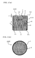
- Figs. 1(a) and 1(b) schematically show an embodiment of a honeycomb structure of the present invention.
- Fig. 1(a) is a cross-sectional view taken along a plane including the central axis (hereinbelow sometimes referred to simply as "axis") (cross-sectional view including the central axis)
- Fig. 1(b) is a cross-sectional view taken along a plane perpendicular to the central axis (cross-sectional view perpendicular to the central axis).
- axis central axis
- Fig. 1(b) is a cross-sectional view taken along a plane perpendicular to the central axis (cross-sectional view perpendicular to the central axis).
- a honeycomb structure 100 of the present embodiment is provided with a honeycomb structured portion 1, and an outer peripheral coat portion 2 disposed in the outer periphery 1b of the honeycomb structured portion 1.
- an end face 2a of the outer peripheral coat portion 2 is located on the inside, in the axial direction, of an end face 1a of the honeycomb structured portion 1.
- “inside, in the axial direction” of "an end face 2a of the outer peripheral coat portion 2 is located on the inside, in the axial direction, of an end face 1a of the honeycomb structured portion” means, as shown in Fig.
- a honeycomb structured portion 1 has porous partition walls separating and forming a plurality of cells functioning as fluid passages and extending in the axial direction.
- end faces 2a of the outer peripheral coat portion in both the end portions 3, 3 in the axial direction are located on the inside, in the axial direction, of the end faces 1a of the honeycomb structured portion.
- an end face 2a of the outer peripheral coat portion may be located on the inside, in the axial direction, of the end face 1a of the honeycomb structural portion.
- a honeycomb structure of the present embodiment is formed in such a manner that, in at least one end portion in the axial direction, the end face of the outer peripheral coat portion is located on the inside, in the axial direction, of the end face of the honeycomb structured portion. Therefore, when the honeycomb structure is fixed in the metal container in the state that both the end portions of the honeycomb structure are held by retainer rings, the retainer rings are inhibited from being brought into contact with end faces of the outer peripheral coat portion, and chipping of the outer peripheral coat portion and partition walls (partition walls of the honeycomb structured portion).
- Fig. 2 is a cross-sectional view including the central axis and schematically showing a state that a honeycomb structure 100 of the present embodiment is fixed in a cylindrical metal container 200.
- the honeycomb structure 100 is held by and fixed in the metal container 200 by disposing a wire mesh mat 203 and a gas seal 202 between the outer periphery of the honeycomb structure 100 (outer periphery of the outer peripheral coat portion).
- a gas seal 202 is disposed near the end portion on the gas inlet port 204 of the metal container 200.
- a honeycomb structure 100 of the present embodiment is formed in such a manner that, in end portions in the axial direction, the end faces of the outer peripheral coat portions are located on the inside, in the axial direction, of the end faces of the honeycomb structured portion. Therefore, it is understood that the retainer rings are brought into contact with the end faces of the honeycomb structured portion and are not brought into contact with end faces of the outer peripheral coat portions. This enables to inhibit the outer peripheral coat portions and partition walls from chipping.
- the distance D in the axial direction between the end faces 2a of the outer peripheral coat portion and the end faces 1a of the honeycomb structured portion is preferably 0.01 mm or more, more preferably 0.1 mm or more, and particularly preferably 0.5 mm or more.
- the distance D in the axial direction is preferably 5 mm or less, more preferably 3 mm or less, and particularly preferably 1 mm or less.
- the distance D is determined as the distance between the position nearest to the end face 1a of the honeycomb structured portion among the end face 2a of the outer peripheral coat portion and the end face 1a of the honeycomb structured portion.
- a honeycomb structure of the present embodiment is provided with plugging portions plugging openings of predetermined cells on one end portion side and openings of remaining cells on the other end portion side. It is further preferable that the predetermined cells and the remaining cells are alternately arranged in such a manner that plugging members are disposed to form a checkerwise pattern at each end face.
- a surface (outer peripheral surface) of the outer periphery 1b preferably has a plurality of grooves 4 extending in the axial direction and being formed by partition walls constituting the outer peripheral surface.
- Such grooves 4 can be formed, for example, by grinding the peripheral edge portion of a honeycomb formed body obtained by extrusion-forming a predetermined raw material to expose partition walls (except for the outer edge portion) forming the cells to the outer peripheral surface. In this case, a portion which has been inside a cell is exposed to the outer peripheral surface, and this portion forms a groove 4 on the outer peripheral surface of the honeycomb structured portion 1.
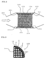
- Fig. 3 schematically shows an embodiment of a honeycomb structure 100 of the present invention and is a cross-sectional view where a part of a cross-section perpendicular to the central axis is enlarged.
- the honeycomb structured portion 1 has porous partition walls separating and forming a plurality of cells extending in the axial direction as described above, and the shape of the honeycomb structured portion is not particularly limited.
- the shape is preferably cylindrical columnar as shown in Figs. 1(a) and 1(b) .
- any shapes may be employed such as a polygonal column, e.g., quadrangular prism and hexagonal prism, and elliptic column.
- the shape of the cross section (cross-section perpendicular to the axial direction) of a cell is not particularly limited, but preferably tetragonal as shown in Fig. 1(b) .
- the shape may be a polygon such as a triangle and a hexagon.
- the porosity and the mean pore diameter of the partition walls of the honeycomb structured portion 1 are not particularly limited as long as the ceramic having the porosity and the mean pore diameter can be used for an exhaust gas treatment or the like.
- the partition walls preferably have a thickness of 100 to 100 ⁇ m, more preferably 200 to 800 ⁇ m.
- the material for the porous partition walls may preferably be ceramic, and further preferably at least one kind selected from the group consisting of cordierite, silicon carbide, sialon, mullite, silicon nitride, zirconium phosphate, zirconia, titania, alumina, and silica.
- the cell density of the honeycomb structured portion 1 is preferably 5 to 300 cells/cm 2 , more preferably 10 to 100 cells/cm 2 , particularly preferably 15 to 50 cells/cm 2 .
- the "outermost periphery 5 of the honeycomb structured portion” means, as shown in Fig. 4 , the outer periphery formed by linking the outermost positions of the partition walls exposed to the outer peripheral surface of the honeycomb structured portion.
- Fig. 4 schematically shows an embodiment of a honeycomb structure of the present invention and is a cross-sectional view where a part of a cross-section perpendicular to the central axis is enlarged.
- the materials described in the Patent Documents 1 and 2 are preferable. There may be employed, for example, a material using powdered potsherd of cordierite, ceramic fibers, and an inorganic binder in combination and a material using cordierite particles and/or ceramic fibers and an oxide matrix of crystalloid formed with colloidal silica or colloidal alumina in combination.
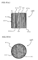
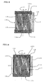
- Figs. 5(a) and 5(b) schematically show another embodiment of a honeycomb structure of the present invention.
- Fig. 5(a) is a cross-sectional view including the central axis
- Fig. 5 (b) is a cross-sectional view perpendicular to the central axis.
- a honeycomb structure 150 of the present embodiment is provided with a honeycomb structured portion 51 and an outer peripheral coat portion 52 disposed on the outer periphery 51b of the honeycomb structural portion 51.
- the end faces 52a of the outer peripheral coat portion 52 are located on the inside, in the axial direction, of the end faces 51a of the honeycomb structured portion 51, and both the end portions in the axial direction are formed to have a tapered shape. Only one end portion in the axial direction may be formed into a tapered shape.
- “the end portions in the axial direction are formed to have a tapered shape” means that the outer peripheral region (tapered portion) 61 of each end face in the axial direction of the honeycomb structure is formed to be inclined in such a manner that the outside becomes closer to the inside in the axial direction than the inside of the tapered portion.
- a honeycomb structure of the present embodiment is constituted in such a manner that the end face of the outer peripheral coat portion is located on the inside, in the axial direction, of the end face of the honeycomb structured portion by forming an end portion in the axial direction into a tapered shape.
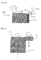
- Fig. 6 schematically shows another embodiment of a honeycomb structure of the present invention and is a partial cross-sectional view where a tapered portion 61 in a cross-section including the central axis is enlarged.
- a honeycomb structure 150 of the present embodiment when the innermost position of the tapered portion 61 is determined as the starting point 62 of tapering, the starting point 62 of tapering is located on the honeycomb structured portion 51.
- an end face 52a of the outer peripheral coat portion is located on the inside, in the axial direction, of an end face 51a of the honeycomb structured portion.
- the entire end face of the outer peripheral coat portion 52 is located on the tapered portion 61 by arranging the starting point 62 of tapering not on the outer peripheral coat portion 52 but on the honeycomb structured portion 51, the entire end face 52a of the outer peripheral coat portion is located on the inside, in the axial direction, of the end face 51a of the honeycomb structured portion.
- the distance in the radial direction from the outermost periphery of the honeycomb structured portion 51 to the starting point 62 of tapering with cell width employed as a standard is preferably 0.5 cell or more, more preferably 1 cell or more, and particularly preferably 1.5 cells or more.
- the distance in the above radial direction is 5 cells or less, more preferably 3 cells or less, particularly preferably 2 cells or less.
- 1 cell means the maximum width in a cross section perpendicular to the axial direction of a cell.
- the length of a diagonal line corresponds to the maximum width, which is the length for "1 cell”.
- the distance H in the axial direction between the starting point 62 of tapering and the terminal point 63 of tapering is preferably 0.01 mm or more, more preferably 0.1 mm or more, and particularly preferably 0.3 mm or more.
- the distance H is preferably 5 mm or less, more preferably 3 mm or less, particularly preferably 2 mm or less, and most preferably 1 mm or less.
- the end face of the honeycomb structure may be formed not in a flat shape but in a mildly protruded shape. In the outer peripheral portion, a slant is formed as the tapered portion is formed.
- a honeycomb structure of the present embodiment is preferably in the same conditions as the case of the aforementioned embodiment of a honeycomb structure of the present invention except for the constitution where an end face of the outer peripheral coat portion is located on the inside, in the axial direction, of the end face of the honeycomb structured portion by forming the end portion in the axial direction into a tapered shape.
- An embodiment of a method for manufacturing a honeycomb structure (first aspect of the manufacturing method) of the'present invention will be described.
- An embodiment of the aforementioned honeycomb structure of the present invention can be manufactured by a manufacturing method of the present embodiment.
- a honeycomb-shaped formed body having a unitarily formed outer wall is manufactured by preparing clay by kneading a predetermined forming raw material and forming the clay.
- the honeycomb-shaped formed body is dried and fired to manufacture a honeycomb formed body.
- the obtained honeycomb formed body has porous partition walls separating and forming a plurality of cells functioning as fluid passages and extending in the axial direction.
- this honeycomb formed body is to serve as the honeycomb structured body constituting a honeycomb structure obtained in a method for manufacturing a honeycomb structure of the present embodiment, elements in common with the honeycomb structured portion constituting the aforementioned embodiment of a honeycomb structure of the present invention preferably satisfy similar conditions.
- a method for preparing clay by kneading the forming raw material there may be employed a method using a kneader, a vacuum kneading machine, or the like.
- the predetermined forming raw material may suitably be selected according to a desired material.
- a method for manufacturing a honeycomb-shaped formed body there may be employed a conventionally known forming method such as extrusion forming, injection forming, and press forming.
- a method of subjecting clay prepared as described above to extrusion forming using a die having predetermined thickness of the outer peripheral wall, thickness of partition walls, and cell density is a suitable example.
- a method for drying there may be employed a conventionally known drying method such as hot air drying, microwave drying, dielectric drying, drying under reduced pressure, vacuum drying, freeze drying, and superheated steam drying.
- a drying method where hot air drying is combined with microwave drying or dielectric drying is preferable so that the entire formed body can be dried quickly and uniformly.
- the drying conditions can suitably be selected according to the shape of the honeycomb-shaped forming body, the material, and the like.
- the honeycomb-shaped formed body dried in the aforementioned method is fired in a furnace to manufacture a honeycomb formed body.
- the furnace and the firing conditions can suitably be selected according to the shape, material, and the like, of the honeycomb-shaped formed body.
- An organic matter such as a binder may be combusted and removed by calcination before firing.
- plugging may be performed on both the end faces in a checkerwise pattern after drying or firing the honeycomb-shaped formed body.
- a known method may be employed as the plugging method.
- FIG. 7 is a cross-sectional view including the axial direction and schematically showing grinding of a peripheral edge portion of a honeycomb formed body with a grinding stone.
- a grinding stone 13 is brought into contact with the outer peripheral wall 12 with rotating a honeycomb-shaped fired body 11 around the central axis to grind the peripheral edge portion including the outer wall 12.
- the grinding stone 13 is brought into contact with the outer wall 12 with being rotated and that the honeycomb-shaped fired body 11 is machined in a traverse grinding method where the entire outer wall of the honeycomb-shaped fired body 11 is ground with moving the grinding stone 13 from one end portion to the other end portion of the honeycomb-shaped fired body 11 in parallel with the central axis thereof in that machining quality is secured.
- chipping may be caused at a corner upon detachment in the end portion where the grinding stone is detached
- a method where the grinding stone is detached outside the honeycomb-shaped fired body 11 in the middle of the honeycomb-shaped fired body 11 to move the other end portion and then grinds the entire outer wail of the honeycomb-shaped fired body 11 with moving the grind stone from the other end portion to the starting end portion in the opposite direction.
- a method for rotating the honeycomb structure 11 and an apparatus therefor There may be employed a plunge grinding where grinding is performed with a grinding stone at one time over the entire length of the honeycomb formed body. Alternatively, substituting for grinding, cutting may be performed with a cutting tool or a screw-shaped cutting tool.
- a ground honeycomb formed body 14 obtained above is held by two cams 15 and 15 each having a depressed portion 16 capable of being engaged with each end portion of the ground-honeycomb formed body 14 in a state that each of the depressed portions 16 and 16 is engaged with each of the end portions 14a and 14a of the ground honeycomb formed body 14; and an outer periphery-coating material 17 is supplied to the outer periphery of the ground honeycomb formed body 14 with leveling the outer periphery-coating material 17 with a spatula 18 in a state that the ground honeycomb formed body 14 and the two cams 15 and 15 are rotated around the axis of the ground honeycomb formed body 14.
- an outer peripheral coat portion 2 is formed on a portion (unengaged portion) 20 other than portions (engaged portions) 19 engaged with the cams 15 of the outer periphery of the ground honeycomb formed body 14 to manufacture a honeycomb structure 100.
- the outer peripheral coat portion 2 is formed in a portion corresponding to a gap between the outer periphery of the ground honeycomb formed body 14 and the spatula 18.
- Fig. 8 is a cross-sectional view including the central axis and schematically showing a step in an embodiment of a method for manufacturing a honeycomb structure (first aspect of the manufacturing method) of the present invention, and Fig.
- FIG. 9 is a cross-sectional view including the central axis and schematically showing a state that a honeycomb structure is manufactured in an embodiment of a method for manufacturing a honeycomb structure (first aspect of the manufacturing method) of the present invention.
- each step is performed with disposing the honeycomb structure in such a state that the direction of the entire length is perpendicular to the surface where the honeycomb structure is disposed in Figs. 7 to 10
- the direction of disposition of the honeycomb structure is not limited in the perpendicular direction, and it may be disposed in the horizontal direction or an oblique direction may be employed to conduct the same steps.
- the outer periphery-coating material 17 is supplied in the state that each of the two cams 15 and 15 is engaged with each of both the end portions of the ground honeycomb formed body 14, the outer periphery-coating material 17 is not applied on the engaged portions 19 which are not exposed outside by the engagement of the cams 15 but applied on the unengaged portion 20 in the state that it is exposed outside because the cams 15 are not engaged therewith.
- This enables to obtain a honeycomb structure where the end portions of the outer peripheral coat portion 2 are located on the inside, in the peripheral direction, of the end faces of the honeycomb structured portion 1 in the end portions in the axial direction.
- the cam 15 having a depressed portion 16 is engaged with at least one end portion of the ground honeycomb formed body 14, and the ground honeycomb formed body may be held between a cam 15 having a depressed portion 16 and a cam having no depressed portion.
- the cam 15 is preferably a disc-shaped (or cylindrical) member having a depressed portion of a predetermined size in the central portion on a face on one side.
- the predetermined size means a diameter with which the cam can be engaged with the ground honeycomb formed body and a depth corresponding to the distance between the end face of the honeycomb structured portion and the end portion of the outer peripheral coat portion of the resultant honeycomb structure. Since the depressed portion of the cam 15 is formed in such a manner that it can be engaged with the end portion of the ground honeycomb formed body, the outer diameter of the cam 15 is larger than that of the ground honeycomb formed body.
- the material for the cam 15, and ceramic, metal, resin, or wood may be'employed. Since a sliding portion of a spatula has hard wear, abrasion resistant material is preferably used.
- the spatula 18 for coating is preferably a plate-like member which is longer than a length of the unengaged portion 20 in the central axial direction.
- the outer periphery-coating material 17 is supplied to the outer periphery of the ground honeycomb formed body 14, it is preferable to level the outer periphery-coating material 17 with bringing a spatula 18 for coating into contact with both the two cams 15 and 15 in such a manner that the spatula 18 is disposed in parallel with the central axis of the ground honeycomb formed body 14.
- the thickness of the outer peripheral coat portion corresponds to the size of the gap between the outermost periphery of the ground honeycomb formed body and the spatula 18 for coating.
- the material for the spatula 18 for coating is not particularly limited, the spatula 18 has hard wear with the holding member 14, abrasion resistant material such as ceramic and metal is suitably used.
- a subtle difference in level is generated on a surface of the coat layer.
- the supply of the coating material is stopped, and the spatula for coating is rotated; or after the completion of coating, the portion having the difference is removed.
- the difference may be left intact.
- the method and apparatus for rotating the ground honeycomb formed body 14 is preferably the same as those for rotating the honeycomb formed body 11 (see Fig. 7 ) described above.
- hot air drying at 100 to 200°C is general as a method for drying the outer peripheral coat layer, outdoor sun drying, indoor natural drying, or a combination with windless drying by an electric heater, far-infrared radiation, or the like, is suitable in order to inhibit the coat layer from crack due to drying.
- a combination with a means for adjusting a drying rate by humidification is suitable.
- the peripheral edge portion of the honeycomb formed body having porous partition walls separating and forming a plurality of cells functioning as fluid passages and extending in the axial direction is ground to form a ground honeycomb formed body. It is preferable that the method for manufacturing a honeycomb formed body and the method for manufacturing the ground honeycomb formed body are the same as those of the aforementioned first aspect of the manufacturing method.
- the ground honeycomb formed body 74 is interposed between the two cams 75 and 75, and the outer periphery-coating material 77 is supplied to the outer periphery of the ground honeycomb formed body 74 with leveling the outer periphery-coating material 77 with the spatula 78 for coating to form the outer peripheral coat portion in the state that the ground honeycomb formed body 74 and the two cams 75 and 75 are rotated around the axis of the round honeycomb formed body 74 to obtain the outer periphery-coated honeycomb formed body 81 having the outer peripheral coat portion 82 as shown in Fig. 11 .
- Fig. 10 is a cross-sectional view including the central axis and schematically showing a step in an embodiment of a method for manufacturing a honeycomb structure (second aspect of the manufacturing method) of the present invention
- Fig. 11 is a cross-sectional view including the central axis and schematically showing an outer periphery-coated honeycomb formed body obtained in an intermediate stage in an embodiment of a method for manufacturing a honeycomb structure (second aspect of the manufacturing method) of the present invention.
- the cams 75 holding both the end portions in the axial direction of the ground honeycomb formed body 74 do not need to have a depressed portion as the cams 15 (see Fig. 18) used in the aforementioned first aspect of the manufacturing method and may hold the end faces of the ground honeycomb formed body with a flat surface.
- the outer periphery-coating material 77 is applied on the entire outer peripheral surface of the ground honeycomb formed body 74 to obtain, as shown in Fig.
- the shape of the cams 75 is not particularly limited, and any shape such as a disk shape and a cylindrical shape may be employed.
- the size (diameter) of the cams 75 is preferably larger than the diameter of the end faces of the honeycomb formed body.
- the shape, material, and method for use of the spatula 78 for coating are preferably the same as those of the spatula 18 for coating in the aforementioned first aspect of the manufacturing method.
- the method and apparatus for rotating the ground honeycomb formed body 74 in the aforementioned first aspect of the manufacturing method is preferably the same as those for the honeycomb formed body 11 (see Fig. 7 ).
- At least one end portion in the.axial direction (outer peripheral portion of an end face in the axial direction) of the outer periphery-coated honeycomb formed body 81 is machined into a tapered shape to manufacture a honeycomb structure.
- the grinding stone 73 is brought into contact with the outer peripheral region of the end face in the axial direction of the outer periphery-coated honeycomb formed body 81 at a predetermined angle.
- FIG. 12 is a cross-sectional view including the central axis and schematically showing a step in an embodiment of a method for manufacturing a honeycomb structure (second aspect of the manufacturing method) of the present invention.
- the angle where the grind stone 73 is brought into contact with the outer peripheral region of an end face in the axial direction of the outer periphery-coated honeycomb formed body 81 and the amount of grinding (depth of grinding in the axial direction or diametral direction) are preferably under the conditions (conditions of the width W and the depth H of the tapered portion) where the shape of the tapered portion 61 (outer peripheral region) in another embodiment (honeycomb structure 150) of a honeycomb structure of the present invention shown in Figs. 5(a), 5(b) , and 6 can be obtained.
- the material for the grinding stone 73 is not particularly limited, and the same material as the grinding stone 13 (see Fig.
- the shape of the grinding stone 73 is not particularly limited, and, for example, a grinding stone having a cone shaped tip with a slant at a predetermined angle as shown in Fig. 12 is preferable. In this case, it is preferable to grind the outer periphery-coated honeycomb formed body with bringing the tip of the cone shape into contact with the end portion of the outer periphery-coated honeycomb formed body and rotating the grinding stone around the central axis of the cone shape.
- both the central axis of the outer periphery-coated formed body and the central axis of the grinding stone are disposed in the vertical direction in that the angle of tapering can easily be adjusted.
- the shape of the grinding stone 73 may simply be a disc shape. In this case, the grinding stone 73 may be brought into contact with the end face of the outer periphery-coated honeycomb formed body while the central axis (center of the rotation) of the disc is inclined with respect to the central axis of the outer periphery-coated honeycomb formed body at a predetermined angle.
- the angle of the inclination of the cone shape and the angle of the central axis of the disc are preferably the angles at which the shape of the tapered portion (outer peripheral region) 61 in another embodiment (honeycomb structure 150) of a honeycomb structure of the present invention shown in Fig. 6 can be formed.
- the method and apparatus for rotating the outer periphery-coated honeycomb formed body 81 are preferably the same as those for rotating the aforementioned honeycomb formed body 11 (see Fig. 7 ).
- a cordierite-forming material was used as a forming material and kneaded with a kneader to prepare clay.
- the clay was subjected to extrusion forming into a honeycomb shape using a die having a cell structure of tetragonal cells of 12 mil/300 cpsi (0.3048 mm/46.5(cells/cm 2 )), a cell pitch of 1.47 mm, and an outer diameter several millimeters larger than 354 mm.
- both the end faces of the honeycomb-shaped formed body were alternately plugged, dried, and fired to obtain a honeycomb formed body.
- the peripheral edge portion of the honeycomb formed body was ground to obtain a ground honeycomb formed body having the diameter of the outermost periphery of 354 mm.
- the outer peripheral coat portion was formed using the cams 15 having a depressed portion and the spatula 18 for coating as shown in Fig. 8 to obtain a honeycomb structure having a diameter of 356 mm where the end faces of the outer peripheral coat portion were located on the inside in the axial direction of the end faces of the honeycomb structured portion.
- the honeycomb structured portion had a length in the axial direction of 432 mm.
- the distance between the end faces of the outer peripheral coat portion and the end faces of the honeycomb structured portion in the axial direction was 0.2 mm.
- a coating material was applied on the outer periphery to obtain an outer periphery-coated honeycomb formed body 81 of 406 mm in diameter ⁇ 432 mmL (length in the axial direction).
- Fig. 11 a coating material was applied on the outer periphery to obtain an outer periphery-coated honeycomb formed body 81 of 406 mm in diameter ⁇ 432 mmL (length in the axial direction).
- the outer peripheral portion of each end face in the axial direction of the outer periphery-coated honeycomb formed body 81 was ground into a tapered shape using a grinding stone to obtain a honeycomb structure where both the end faces were formed into a tapered shape as shown in Figs. 5(a) and 5(b) .
- the width W of the tapered portion was 5 mm
- the depth H of the tapered portion was 0.4 mm.
- Example 1 As a honeycomb structure in Comparative Example 1, an outer periphery-coated honeycomb formed body 81 shown in Fig. 11 and having the same size and cell structure as in Example 2 was manufactured in the same manner as in Example 2.
- honeycomb structures of Examples 1, 2 and Comparative Example 1 were subjected to canning in a converter to perform a burner spalling test where heating with a gas burner and cooling are repeated under the following conditions, and the state of the end faces of each honeycomb structure was observed.
- Test apparatus Gas burner spalling apparatus Heating condition (for one cycle): Temperature was raised from 100(lowest temperature) to 750°C (highest temperature) for ten minutes, kept at 750°C for 10 minutes, lowered from 750 to 100°C for 30 minutes, and kept at 100°C for 10 minutes. Number of heating cycle: 200 cycles
- the honeycomb structure of Example 1 had no chipped portion at the end faces of the outer peripheral coat portion and little chipped portion in the outer peripheral portion of the end face of the honeycomb structured portion.
- the chipping was not particularly a matter of use of the honeycomb structure.
- the honeycomb structure of Example 2 had no chipping in either the outer peripheral coat portion or the honeycomb structured portion.
- the honeycomb structure of Comparative Example 1 had large chipped portion on the end faces of both the outer peripheral coat portion and the honeycomb structured portion. From these results, it is understood that chipping of the end face can be inhibited by the constitution where the end faces of the outer peripheral coat portion are located on the inside, in the axial direction, of the end faces of the honeycomb structured portion.
- the present invention can be used in order to trap particulate matter such as dust contained in automobile exhaust gas or combustion exhaust gas or the like generated upon combustion of wastes and further in order to adsorb and absorb NO x , CO, HC, and the like, in the above exhaust gas by a catalyst loaded on the honeycomb structures and can inhibit damages such as chipping in an end portion from being caused upon a treatment of exhaust gas or the like while the honeycomb structure of the present invention is fixed in a metal container.
Landscapes
- Chemical & Material Sciences (AREA)
- Chemical Kinetics & Catalysis (AREA)
- Engineering & Computer Science (AREA)
- Physics & Mathematics (AREA)
- Geometry (AREA)
- Combustion & Propulsion (AREA)
- Health & Medical Sciences (AREA)
- Toxicology (AREA)
- Ceramic Engineering (AREA)
- Mechanical Engineering (AREA)
- General Engineering & Computer Science (AREA)
- Materials Engineering (AREA)
- Organic Chemistry (AREA)
- Catalysts (AREA)
- Filtering Materials (AREA)
- Exhaust Gas After Treatment (AREA)
- Devices For Post-Treatments, Processing, Supply, Discharge, And Other Processes (AREA)
Applications Claiming Priority (2)
| Application Number | Priority Date | Filing Date | Title |
|---|---|---|---|
| JP2006183050 | 2006-07-03 | ||
| PCT/JP2007/063039 WO2008004492A1 (fr) | 2006-07-03 | 2007-06-28 | Structure en nid d'abeilles et procédé pour sa fabrication |
Publications (3)
| Publication Number | Publication Date |
|---|---|
| EP2036609A1 true EP2036609A1 (fr) | 2009-03-18 |
| EP2036609A4 EP2036609A4 (fr) | 2012-05-09 |
| EP2036609B1 EP2036609B1 (fr) | 2014-01-29 |
Family
ID=38894464
Family Applications (1)
| Application Number | Title | Priority Date | Filing Date |
|---|---|---|---|
| EP07767832.4A Ceased EP2036609B1 (fr) | 2006-07-03 | 2007-06-28 | Structure en nid d'abeilles et procédé pour sa fabrication |
Country Status (5)
| Country | Link |
|---|---|
| US (1) | US20080176029A1 (fr) |
| EP (1) | EP2036609B1 (fr) |
| JP (1) | JP5361374B2 (fr) |
| CN (1) | CN101346184B (fr) |
| WO (1) | WO2008004492A1 (fr) |
Cited By (1)
| Publication number | Priority date | Publication date | Assignee | Title |
|---|---|---|---|---|
| EP2724814A3 (fr) * | 2012-09-25 | 2016-12-07 | NGK Insulators, Ltd. | Procédé de meulage d'une structure en nid d'abeille |
Families Citing this family (17)
| Publication number | Priority date | Publication date | Assignee | Title |
|---|---|---|---|---|
| JP4998346B2 (ja) * | 2008-03-25 | 2012-08-15 | 株式会社デンソー | セラミックハニカム構造体の製造方法 |
| JP4975689B2 (ja) * | 2008-07-03 | 2012-07-11 | 日本碍子株式会社 | ハニカム構造体 |
| US8617659B2 (en) * | 2008-08-29 | 2013-12-31 | Corning Incorporated | Methods of applying a layer to a honeycomb body |
| JP5877622B2 (ja) * | 2009-02-13 | 2016-03-08 | 日本碍子株式会社 | ハニカム構造体 |
| JP5280922B2 (ja) * | 2009-03-31 | 2013-09-04 | 日本碍子株式会社 | 目封止ハニカム構造体、およびそれを用いたディーゼルパティキュレートフィルタ |
| CN103221772B (zh) * | 2010-11-18 | 2016-08-31 | 日本碍子株式会社 | 导热构件 |
| SE536327C2 (sv) | 2011-11-22 | 2013-08-20 | Scania Cv Ab | Arrangemang för montering av en avgasrenande enhet i en avgaspassage |
| US9962770B2 (en) | 2012-04-02 | 2018-05-08 | Hitachi Metals, Ltd. | Method for producing ceramic honeycomb body |
| JP5805039B2 (ja) * | 2012-09-25 | 2015-11-04 | 日本碍子株式会社 | ハニカム構造体 |
| JP5620447B2 (ja) * | 2012-09-25 | 2014-11-05 | 日本碍子株式会社 | ハニカム構造体の外周塗工方法 |
| JP6012369B2 (ja) * | 2012-09-26 | 2016-10-25 | 日本碍子株式会社 | 目封止ハニカム構造体 |
| JP6014526B2 (ja) * | 2013-03-22 | 2016-10-25 | 日本碍子株式会社 | ハニカム構造体 |
| JP6059181B2 (ja) * | 2013-06-11 | 2017-01-11 | 日本碍子株式会社 | ハニカム構造体 |
| JP6068274B2 (ja) * | 2013-06-11 | 2017-01-25 | 日本碍子株式会社 | ハニカム構造体 |
| JP6206345B2 (ja) * | 2014-06-30 | 2017-10-04 | 株式会社デンソー | ハニカム構造体及びハニカム構造体の設計方法 |
| JP6393340B2 (ja) * | 2014-12-04 | 2018-09-19 | 本田技研工業株式会社 | 内燃機関の排気浄化装置及びその製造方法 |
| JP5965002B2 (ja) * | 2015-02-04 | 2016-08-03 | 日本碍子株式会社 | ハニカム構造体 |
Citations (3)
| Publication number | Priority date | Publication date | Assignee | Title |
|---|---|---|---|---|
| JP2004255377A (ja) * | 2003-02-07 | 2004-09-16 | Hitachi Metals Ltd | セラミックハニカム構造体 |
| EP1538133A1 (fr) * | 2003-06-23 | 2005-06-08 | Ibiden Co., Ltd. | Structure alveolaire |
| US20050229565A1 (en) * | 2004-04-05 | 2005-10-20 | Ibiden Co., Ltd. | Honeycomb structural body, manufacturing method of the honeycomb structural body, and exhaust gas purifying device |
Family Cites Families (13)
| Publication number | Priority date | Publication date | Assignee | Title |
|---|---|---|---|---|
| JPS56162220A (en) * | 1980-05-20 | 1981-12-14 | Ngk Insulators Ltd | Ceramic honeycomb structural body |
| JPS6272553A (ja) * | 1985-09-25 | 1987-04-03 | トヨタ自動車株式会社 | モノリス触媒担体の製造方法 |
| JP2604876B2 (ja) | 1990-03-27 | 1997-04-30 | 日本碍子株式会社 | セラミックハニカム構造体の製造方法 |
| US5629067A (en) * | 1992-01-30 | 1997-05-13 | Ngk Insulators, Ltd. | Ceramic honeycomb structure with grooves and outer coating, process of producing the same, and coating material used in the honeycomb structure |
| JP2613729B2 (ja) | 1992-01-30 | 1997-05-28 | 日本碍子株式会社 | セラミックハニカム構造体及びその製造法並びにそのためのコート材 |
| KR100446205B1 (ko) * | 1999-09-29 | 2004-08-31 | 이비덴 가부시키가이샤 | 하니콤 필터 및 세라믹 필터 집합체, 그리고 이를 갖는 배기가스 정화장치 |
| JP3803009B2 (ja) * | 1999-09-29 | 2006-08-02 | イビデン株式会社 | セラミックフィルタ集合体 |
| JP4680437B2 (ja) * | 2001-07-13 | 2011-05-11 | 日本碍子株式会社 | ハニカム構造体 |
| JP4331575B2 (ja) * | 2003-11-26 | 2009-09-16 | 日本碍子株式会社 | ハニカム構造体及びその製造方法、並びに接合材 |
| JP2006218851A (ja) * | 2005-01-14 | 2006-08-24 | Denso Corp | セラミックハニカム構造体の製造方法及びセラミックハニカム構造体 |
| CN1817452A (zh) * | 2005-01-14 | 2006-08-16 | 株式会社电装 | 蜂窝陶瓷结构体及其制造方法 |
| DE102006056462A1 (de) * | 2006-11-28 | 2008-05-29 | Dr. Johannes Heidenhain Gmbh | Drehgeber |
| ES2577328T3 (es) * | 2006-12-04 | 2016-07-14 | Telit Automotive Solutions Nv | Registrador de datos de vehículo |
-
2007
- 2007-06-28 WO PCT/JP2007/063039 patent/WO2008004492A1/fr active Application Filing
- 2007-06-28 JP JP2008503303A patent/JP5361374B2/ja not_active Expired - Fee Related
- 2007-06-28 CN CN200780000879.8A patent/CN101346184B/zh active Active
- 2007-06-28 EP EP07767832.4A patent/EP2036609B1/fr not_active Ceased
-
2008
- 2008-01-22 US US12/017,756 patent/US20080176029A1/en not_active Abandoned
Patent Citations (3)
| Publication number | Priority date | Publication date | Assignee | Title |
|---|---|---|---|---|
| JP2004255377A (ja) * | 2003-02-07 | 2004-09-16 | Hitachi Metals Ltd | セラミックハニカム構造体 |
| EP1538133A1 (fr) * | 2003-06-23 | 2005-06-08 | Ibiden Co., Ltd. | Structure alveolaire |
| US20050229565A1 (en) * | 2004-04-05 | 2005-10-20 | Ibiden Co., Ltd. | Honeycomb structural body, manufacturing method of the honeycomb structural body, and exhaust gas purifying device |
Non-Patent Citations (1)
| Title |
|---|
| See also references of WO2008004492A1 * |
Cited By (1)
| Publication number | Priority date | Publication date | Assignee | Title |
|---|---|---|---|---|
| EP2724814A3 (fr) * | 2012-09-25 | 2016-12-07 | NGK Insulators, Ltd. | Procédé de meulage d'une structure en nid d'abeille |
Also Published As
| Publication number | Publication date |
|---|---|
| US20080176029A1 (en) | 2008-07-24 |
| CN101346184A (zh) | 2009-01-14 |
| WO2008004492A1 (fr) | 2008-01-10 |
| JP5361374B2 (ja) | 2013-12-04 |
| EP2036609B1 (fr) | 2014-01-29 |
| CN101346184B (zh) | 2012-07-11 |
| JPWO2008004492A1 (ja) | 2009-12-03 |
| EP2036609A4 (fr) | 2012-05-09 |
Similar Documents
| Publication | Publication Date | Title |
|---|---|---|
| EP2036609B1 (fr) | Structure en nid d'abeilles et procédé pour sa fabrication | |
| EP2039428B1 (fr) | Sturcture en nid d'abeilles et son procédé de fabrication | |
| EP1679120B1 (fr) | Structure en nid d'abeille et son procede de production | |
| CN100419230C (zh) | 蜂窝结构体、蜂窝结构体的制造方法以及废气净化装置 | |
| EP2119487B1 (fr) | Structure en nid d'abeilles et son procédé de fabrication | |
| CN203710819U (zh) | 集尘用蜂窝过滤器 | |
| US7396576B2 (en) | Honeycomb structure | |
| US20040128991A1 (en) | Honeycomb structure | |
| JP5805039B2 (ja) | ハニカム構造体 | |
| EP2177253B1 (fr) | Structure en nid d'abeille | |
| EP2127719B1 (fr) | Structure en nid d'abeille | |
| EP2366444B1 (fr) | Structure en nid d'abeille | |
| EP2108436A1 (fr) | Structure en nid d'abeille et son procédé de fabrication | |
| JP2012521345A (ja) | ハニカム構造を硬化させるための方法及び基材 | |
| JP6068274B2 (ja) | ハニカム構造体 | |
| JP6673209B2 (ja) | セラミックハニカム構造体及びその製造方法、並びにハニカム成形用金型 | |
| EP2108430A1 (fr) | Structure en nid d'abeille | |
| JP5501631B2 (ja) | ハニカム構造体 | |
| EP2221099B1 (fr) | Structure en nid d'abeille | |
| EP2127720B1 (fr) | Structure en nids d'abeille | |
| EP2505253B1 (fr) | Structure en nid d'abeille raccordée | |
| JP5450010B2 (ja) | ハニカム構造体 | |
| EP2508241A1 (fr) | Structure en nid d'abeille raccordée | |
| JP2016175789A (ja) | ハニカム構造体 |
Legal Events
| Date | Code | Title | Description |
|---|---|---|---|
| PUAI | Public reference made under article 153(3) epc to a published international application that has entered the european phase |
Free format text: ORIGINAL CODE: 0009012 |
|
| 17P | Request for examination filed |
Effective date: 20080220 |
|
| AK | Designated contracting states |
Kind code of ref document: A1 Designated state(s): AT BE BG CH CY CZ DE DK EE ES FI FR GB GR HU IE IS IT LI LT LU LV MC MT NL PL PT RO SE SI SK TR |
|
| AX | Request for extension of the european patent |
Extension state: AL BA HR MK RS |
|
| DAX | Request for extension of the european patent (deleted) | ||
| RBV | Designated contracting states (corrected) |
Designated state(s): DE FR |
|
| A4 | Supplementary search report drawn up and despatched |
Effective date: 20120405 |
|
| RIC1 | Information provided on ipc code assigned before grant |
Ipc: B01D 46/24 20060101ALI20120330BHEP Ipc: B01D 39/20 20060101ALI20120330BHEP Ipc: B01D 39/00 20060101ALI20120330BHEP Ipc: B01D 46/00 20060101ALI20120330BHEP Ipc: B01D 53/86 20060101ALI20120330BHEP Ipc: F01N 3/28 20060101ALI20120330BHEP Ipc: B01J 35/04 20060101AFI20120330BHEP |
|
| GRAP | Despatch of communication of intention to grant a patent |
Free format text: ORIGINAL CODE: EPIDOSNIGR1 |
|
| INTG | Intention to grant announced |
Effective date: 20130731 |
|
| GRAS | Grant fee paid |
Free format text: ORIGINAL CODE: EPIDOSNIGR3 |
|
| GRAA | (expected) grant |
Free format text: ORIGINAL CODE: 0009210 |
|
| AK | Designated contracting states |
Kind code of ref document: B1 Designated state(s): DE FR |
|
| REG | Reference to a national code |
Ref country code: DE Ref legal event code: R096 Ref document number: 602007035004 Country of ref document: DE Effective date: 20140313 |
|
| REG | Reference to a national code |
Ref country code: DE Ref legal event code: R097 Ref document number: 602007035004 Country of ref document: DE |
|
| PLBE | No opposition filed within time limit |
Free format text: ORIGINAL CODE: 0009261 |
|
| STAA | Information on the status of an ep patent application or granted ep patent |
Free format text: STATUS: NO OPPOSITION FILED WITHIN TIME LIMIT |
|
| 26N | No opposition filed |
Effective date: 20141030 |
|
| REG | Reference to a national code |
Ref country code: DE Ref legal event code: R097 Ref document number: 602007035004 Country of ref document: DE Effective date: 20141030 |
|
| REG | Reference to a national code |
Ref country code: FR Ref legal event code: PLFP Year of fee payment: 10 |
|
| REG | Reference to a national code |
Ref country code: FR Ref legal event code: PLFP Year of fee payment: 11 |
|
| REG | Reference to a national code |
Ref country code: FR Ref legal event code: PLFP Year of fee payment: 12 |
|
| PGFP | Annual fee paid to national office [announced via postgrant information from national office to epo] |
Ref country code: DE Payment date: 20210602 Year of fee payment: 15 Ref country code: FR Payment date: 20210513 Year of fee payment: 15 |
|
| REG | Reference to a national code |
Ref country code: DE Ref legal event code: R119 Ref document number: 602007035004 Country of ref document: DE |
|
| PG25 | Lapsed in a contracting state [announced via postgrant information from national office to epo] |
Ref country code: FR Free format text: LAPSE BECAUSE OF NON-PAYMENT OF DUE FEES Effective date: 20220630 |
|
| PG25 | Lapsed in a contracting state [announced via postgrant information from national office to epo] |
Ref country code: DE Free format text: LAPSE BECAUSE OF NON-PAYMENT OF DUE FEES Effective date: 20230103 |