EP2034249A1 - Vorrichtung zum Einbau eines Solarzellenpaneels auf einem Dach - Google Patents
Vorrichtung zum Einbau eines Solarzellenpaneels auf einem Dach Download PDFInfo
- Publication number
- EP2034249A1 EP2034249A1 EP08164011A EP08164011A EP2034249A1 EP 2034249 A1 EP2034249 A1 EP 2034249A1 EP 08164011 A EP08164011 A EP 08164011A EP 08164011 A EP08164011 A EP 08164011A EP 2034249 A1 EP2034249 A1 EP 2034249A1
- Authority
- EP
- European Patent Office
- Prior art keywords
- frame
- solar panel
- roof
- connection
- width
- Prior art date
- Legal status (The legal status is an assumption and is not a legal conclusion. Google has not performed a legal analysis and makes no representation as to the accuracy of the status listed.)
- Granted
Links
- 241000446313 Lamella Species 0.000 claims description 15
- 241000237536 Mytilus edulis Species 0.000 claims description 2
- 235000020638 mussel Nutrition 0.000 claims description 2
- 230000010354 integration Effects 0.000 description 12
- 238000009434 installation Methods 0.000 description 8
- 238000007789 sealing Methods 0.000 description 4
- XLYOFNOQVPJJNP-UHFFFAOYSA-N water Substances O XLYOFNOQVPJJNP-UHFFFAOYSA-N 0.000 description 3
- 230000006978 adaptation Effects 0.000 description 2
- 238000010586 diagram Methods 0.000 description 2
- 238000004078 waterproofing Methods 0.000 description 2
- 230000004888 barrier function Effects 0.000 description 1
- 230000000295 complement effect Effects 0.000 description 1
- 230000007547 defect Effects 0.000 description 1
- 230000000694 effects Effects 0.000 description 1
- 229940082150 encore Drugs 0.000 description 1
- 230000005484 gravity Effects 0.000 description 1
- WABPQHHGFIMREM-UHFFFAOYSA-N lead(0) Chemical compound [Pb] WABPQHHGFIMREM-UHFFFAOYSA-N 0.000 description 1
- 238000000034 method Methods 0.000 description 1
- 230000000149 penetrating effect Effects 0.000 description 1
Images


Classifications
-
- F—MECHANICAL ENGINEERING; LIGHTING; HEATING; WEAPONS; BLASTING
- F24—HEATING; RANGES; VENTILATING
- F24S—SOLAR HEAT COLLECTORS; SOLAR HEAT SYSTEMS
- F24S40/00—Safety or protection arrangements of solar heat collectors; Preventing malfunction of solar heat collectors
- F24S40/40—Preventing corrosion; Protecting against dirt or contamination
- F24S40/44—Draining rainwater or condensation
-
- F—MECHANICAL ENGINEERING; LIGHTING; HEATING; WEAPONS; BLASTING
- F24—HEATING; RANGES; VENTILATING
- F24S—SOLAR HEAT COLLECTORS; SOLAR HEAT SYSTEMS
- F24S20/00—Solar heat collectors specially adapted for particular uses or environments
- F24S20/60—Solar heat collectors integrated in fixed constructions, e.g. in buildings
- F24S20/67—Solar heat collectors integrated in fixed constructions, e.g. in buildings in the form of roof constructions
-
- F—MECHANICAL ENGINEERING; LIGHTING; HEATING; WEAPONS; BLASTING
- F24—HEATING; RANGES; VENTILATING
- F24S—SOLAR HEAT COLLECTORS; SOLAR HEAT SYSTEMS
- F24S25/00—Arrangement of stationary mountings or supports for solar heat collector modules
- F24S25/20—Peripheral frames for modules
-
- F—MECHANICAL ENGINEERING; LIGHTING; HEATING; WEAPONS; BLASTING
- F24—HEATING; RANGES; VENTILATING
- F24S—SOLAR HEAT COLLECTORS; SOLAR HEAT SYSTEMS
- F24S25/00—Arrangement of stationary mountings or supports for solar heat collector modules
- F24S25/30—Arrangement of stationary mountings or supports for solar heat collector modules using elongate rigid mounting elements extending substantially along the supporting surface, e.g. for covering buildings with solar heat collectors
- F24S25/33—Arrangement of stationary mountings or supports for solar heat collector modules using elongate rigid mounting elements extending substantially along the supporting surface, e.g. for covering buildings with solar heat collectors forming substantially planar assemblies, e.g. of coplanar or stacked profiles
-
- Y—GENERAL TAGGING OF NEW TECHNOLOGICAL DEVELOPMENTS; GENERAL TAGGING OF CROSS-SECTIONAL TECHNOLOGIES SPANNING OVER SEVERAL SECTIONS OF THE IPC; TECHNICAL SUBJECTS COVERED BY FORMER USPC CROSS-REFERENCE ART COLLECTIONS [XRACs] AND DIGESTS
- Y02—TECHNOLOGIES OR APPLICATIONS FOR MITIGATION OR ADAPTATION AGAINST CLIMATE CHANGE
- Y02B—CLIMATE CHANGE MITIGATION TECHNOLOGIES RELATED TO BUILDINGS, e.g. HOUSING, HOUSE APPLIANCES OR RELATED END-USER APPLICATIONS
- Y02B10/00—Integration of renewable energy sources in buildings
- Y02B10/20—Solar thermal
-
- Y—GENERAL TAGGING OF NEW TECHNOLOGICAL DEVELOPMENTS; GENERAL TAGGING OF CROSS-SECTIONAL TECHNOLOGIES SPANNING OVER SEVERAL SECTIONS OF THE IPC; TECHNICAL SUBJECTS COVERED BY FORMER USPC CROSS-REFERENCE ART COLLECTIONS [XRACs] AND DIGESTS
- Y02—TECHNOLOGIES OR APPLICATIONS FOR MITIGATION OR ADAPTATION AGAINST CLIMATE CHANGE
- Y02E—REDUCTION OF GREENHOUSE GAS [GHG] EMISSIONS, RELATED TO ENERGY GENERATION, TRANSMISSION OR DISTRIBUTION
- Y02E10/00—Energy generation through renewable energy sources
- Y02E10/40—Solar thermal energy, e.g. solar towers
- Y02E10/47—Mountings or tracking
Definitions
- the invention relates to a solar panel integration device on a roof.
- the invention more specifically relates to a thermal solar panel integration device on a roof tile interlocking, made in kit.
- the invention also relates to an assembly formed by a plurality of solar panels and a device according to the invention.
- the invention relates to such an assembly comprising a plurality of solar panels arranged horizontally next to each other.
- the invention further relates to a roof provided with such an assembly.
- the invention may especially be applied to a roof comprising tiles of a range of tiles of the family "Grands Moules du Sud", and as a non-limiting example to a tile of this family called Romane Canal by the plaintiff , which has an important curve.
- DE 103 21 422 proposes fixing means for solar panel with specific corner pieces.
- US 20050217665 proposes a fixing system for solar panel not penetrating into the support surface.
- WO 00/12839 proposes a structure and a method adapted for the assembly of solar panel.
- WO 2004/035954 proposes a device for fixing solar panels.
- An object of the invention is therefore to provide a solar panel integration device on a roof, and more particularly for an application of solar thermal type, to strengthen the seal at the junction between the solar panels.
- an object of the invention is to provide an integration device for overcoming the defects presented above.
- An object of the invention is more precisely to provide such a device well suited for the integration of a solar panel, particularly of the solar thermal type, to a roof made with a range of tiles of the family "Grands Moules du Sud” .
- Another objective is to propose an assembly formed by at least one solar panel and a device according to the invention.
- Another objective is still to provide a roof comprising such an assembly, comprising a plurality of panels arranged horizontally next to each other.
- the device for integrating a plurality of solar panels on a roof comprises an upper connection 100 between the upper part 11 of a solar panel (10) and the roof, a lower connection 200 between the lower part 12 of the solar panel and the roof, and a central corridor 600.
- Each solar panel having a frame 15, the symmetrically shaped upper connector 100 is arranged so that it connects with two solar panel frames 15 arranged next to each other over an upper half-width of said frame.
- the lower connection 200 of symmetrical shape is arranged so that it provides the connection with the same two frames, on a lower half-width of said frame.
- the central corridor 600 is in turn arranged in a U-shape to ensure a covering with the upper connection 100, the lower connection 200 and the two frames 15 arranged next to each other.
- the central corridor 600 is sandwiched between these two frames and extends according to the height thereof.
- Each of the flanges 611, 612 of the central aisle 600 has a height and shape adapted to engage a sipe 17, 18 attached to the adjoining solar panel frame side ( figures 1 , 3 and 5 ).
- the upper connector 100 further comprises a corridor 110 arranged in the shape of a U (U-shaped section) whose sides or flanges 111, 112 respectively form a lateral abutment to one of the two chassis members. solar panel between which the corridor is arranged.
- These sides 111, 112 are also arranged to engage with a lamella of cross section fixed on the side of the frame. For this purpose they therefore have a shape allowing this arrangement. (height, thickness, flat top).
- the upper connector 100 also comprises two upper stops 120, 130 arranged to bear against the rear face of one of the two frames. For this purpose, they are arranged symmetrically and perpendicularly with respect to the axis of the corridor 110.
- the frame of a solar panel is thus correctly maintained at its corners ( Figures 2, 3 ). It also includes the guides 160 and 170, in the extension of the stops.
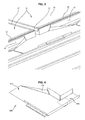
- the upper connector 100 also comprises a flat portion 140 comprising a rim 150 extending perpendicularly to the flat portion 140 and in the direction of the length of the upper connector 100, and having a predetermined height H to maintain in position the tiles of the directly adjacent to the upper connection 100. In the absence of such a room 150, the row of tiles in contact with the device would not be in alignment with the roof and problems of sealing and general aesthetics would be encountered ( figure 2 ).
- the lower connection 200 comprises a U-shaped corridor 210 whose sides or flanges 211, 212 respectively form lateral stops to one of the two solar panel frames between which this corridor 210 is disposed.
- These sides 211, 212 have a suitable shape (height, thickness, planar upper part) for engaging a lamella 17, 18 of cross section fixed on the corresponding side of the frame 15 ( Figures 9, 11 ).
- the lower connection 200 also comprises two lower stops 220, 230 arranged symmetrically and perpendicular to the axis of the corridor 210, of length adapted to the half-width of a frame. These stops 220, 230 have a suitable shape (height, thickness, flat top) to engage with a strip 19 of cross-section fixed on the front face of the corresponding chassis ( Figures 9, 11 ).
- the strips 17, 18, 19 are fixed by any means adapted to the frame so that there is a day 170 between them and the frame.
- the device also comprises corner connectors 500, 700 which make it possible to connect a lateral corridor (which will be described later), the solar panel frame, both on the side of the latter and on its upper part, and similar to the upper connector 100.
- corner connectors 500, 700 which make it possible to connect a lateral corridor (which will be described later), the solar panel frame, both on the side of the latter and on its upper part, and similar to the upper connector 100.
- the first corner joints 500 comprise a first part 510 arranged to connect with an upper half-width of a frame and a second part 520, perpendicular to the first part 510, arranged in the form of a U-shaped section for come into engagement with a lamella 17 fixed on the side of the chassis ( figures 4 , 5, 6 ), as well as a guide 530.
- the second corner fittings 700 comprise a first portion 710 arranged to connect with a lower half-width of a frame and a second portion 720, perpendicular to the first portion 710, arranged in the form of a U-shaped channel for come into engagement with a lamella 17 fixed on the side of the chassis ( Figures 10, 11 ).
- the first portion 710 of a second corner connector 700 is also arranged to engage a lamella 19 of cross section fixed on the front face of the frame.
- the cover 800 includes interlocking means 810 with a solar panel frame 15.
- These interlocking means 810 comprise a stop 811 and a guide 812, 813 at each end of the abutment 810 extending perpendicular to the abutment 810.
- These interlocking means 810 thus have a U-shaped section, intended to receive the upper part of frame 15 of the solar panel 10.
- the interlocking means have a length adapted to the width of the frame 15 of the solar panel.
- the interlocking means 810 of the cover also comprise a clip 814 extending in the extension of the abutment 810, over the entire length thereof ( Figures 7, 8 ).
- the section of this clip 814 is arranged to engage with a strip 16 of cross section fixed on the upper part of the frame 15 of the solar panel 10, while covering the strip 16 for sealing.
- the strip 16 is fixed on the frame so that there is a day between this strip 16 and the solar panel ( figures 3 , 5 , 6 and 8 ).
- the clip 814 makes it possible to protect the upper face of the upper part of the frame 15, which strengthens the seal.
- the presence of this clip 814, in combination with the lamella 16 fixed on the solar panel, is particularly well suited to ensure tightness for weak slopes of the roof, that is to say typically between 10 ° and 30 °, and also improves the aesthetic appearance of the integration of the solar panel 10 on the roof.
- the cover 800 is arranged vis-à-vis a solar panel frame, unlike the upper connectors 100 which protect, on half a frame width, two solar panel frames.
- the lid 800 is thus mounted in a staggered manner above two upper fitting halves 100. Such an arrangement helps to keep the upper fittings properly in place and improves the tightness of the device.
- the cover 800 comprises a planar portion 815 having a flange 816 extending perpendicularly to the planar portion 815 and in the direction of the length of the cover 800, and having a predetermined height H to maintain in position directly adjacent roof tiles. at the lid 800.
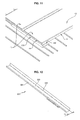
- each passage 300, 400 of U-shaped section is arranged on the one hand to ensure a covering with the first and second corner connectors 500, 700 and secondly to engage a lamella 17, 18 of right section fixed on the side of the corresponding chassis.
- the corridors 300, 400 as well as the upper 100 and lower 200 and the cover 800 have a sufficient width to sufficiently cover the roof elements adjacent to the solar panel, and to ensure a perfect seal.
- the folds 301, 401 of the corridors 300, 400 are particularly well suited to the range of tiles "Grands Moules du Sud", and even more particularly to the so-called Romane Canal tiles.
- the assembly is such that the right end of the curved portion of the "Grands Moules du Sud” type tile comes into abutment on the outer portion of the fold 301 of the left lane 300, the flat portion of the tile in continuity with this curved portion being inserted below the first portion 320 of the corridor 300.
- the assembly is such that the left end of the curved portion engages with the fold 401 inside the corridor 400.
- the first portion 320, 420 corridors 300, 400 has a greater width than conventional corridors, namely a width I1 of the order of 4cm, while typically the width of the corridors is of the order of 3cm. This is particularly well suited to the constraints of low slope roofs, this width to increase the flow of water likely to flow on these corridors 300, 400. Incidentally, it prevents sheets from getting stuck in the corridors.
- the corridors here play a role of gutters, to which the water is redirected by means of the elements 160, 170 and 530.
- the second part or flange 330, 430 is for its part to be pressed against the solar panel, so there is no day between it and the solar panel to ensure a good seal.
- the flanges 330, 430 are arranged (thickness, height) to engage a lamella, of cross section, fixed on the side of a frame.
- a possibility of connection between the lower connection 200 and the adjoining roof portion is to use a lead flap.
- This flap is disposed on the end of the curved portion of the tile and cooperates with a curved flange 240 of the lower connector 200 to seal.
- These, of the interlocking tile type comprise at least one curved part, a flat end portion, with a width of between 100 and 140 mm, in the upper extension of the curved part, the flat end portion comprising at least a chute extending over the entire width of said planar portion.
- each of these tiles is arranged in the lower part of the assembly formed by the device according to the invention and the solar panel.
- This solution does not require the installation of a lead flap, which allows a faster installation.
- the invention also relates to an assembly comprising a device as described above and a plurality of solar panels 10, in particular solar thermal type, each comprising a frame 15 comprising a first strip 16 fixed on the upper face of the frame 15 of so that there is a day between this lamella 16 and the solar panel; and a second blade 19 fixed on the front face of the frame so that there is a day between this blade and the front face of the frame.
- This assembly further comprises a third strip 17 fixed on the left side of the frame so that there is a day between the strip and the left side of the frame; and a fourth blade 18 fixed on the right side of the frame so that there is a day between this blade and the right side of the frame.
- the invention further relates to a roof comprising an assembly as described above, and comprising a plurality of tiles of the South Big Mussel type whose right end of the curved portion abuts against the outer portion of a fold 301 of the left aisle 300 of the set.
- the roof may include a plurality of tiles of the type Southern Big Mussels whose left end of the curved portion engages a fold 401 within the right lateral aisle 400 of the assembly.
- the roof may further comprise a plurality of interlocking tiles, arranged at the bottom of said sets, each tile having at least one curved portion and a flat end portion in the upper extension of the curved portion, the portion of flat end, a width between 100mm and 140mm being covered by the lower connection 200.
- the device according to the invention therefore has many advantages.
- the device according to the invention makes it possible to better integrate the solar panel 10 at the roof, in particular the solar thermal panel, by means matching the shape of the panel.
- the device according to the invention can quite adapt to any type of solar panel. It suffices for it to mount means such as the slats 16, 17, 18, 19 or any other means offering an equivalent function.
Landscapes
- Engineering & Computer Science (AREA)
- Physics & Mathematics (AREA)
- Life Sciences & Earth Sciences (AREA)
- Sustainable Development (AREA)
- Sustainable Energy (AREA)
- Thermal Sciences (AREA)
- Chemical & Material Sciences (AREA)
- Combustion & Propulsion (AREA)
- Mechanical Engineering (AREA)
- General Engineering & Computer Science (AREA)
- Roof Covering Using Slabs Or Stiff Sheets (AREA)
Applications Claiming Priority (1)
| Application Number | Priority Date | Filing Date | Title |
|---|---|---|---|
| FR0757468A FR2920800A1 (fr) | 2007-09-10 | 2007-09-10 | Dispositif d'integration de panneau solaire sur un toit |
Publications (2)
| Publication Number | Publication Date |
|---|---|
| EP2034249A1 true EP2034249A1 (de) | 2009-03-11 |
| EP2034249B1 EP2034249B1 (de) | 2013-06-12 |
Family
ID=39201874
Family Applications (1)
| Application Number | Title | Priority Date | Filing Date |
|---|---|---|---|
| EP08164011.2A Active EP2034249B1 (de) | 2007-09-10 | 2008-09-10 | Einrichtung umfassend mehrere Solarpaneele und Vorrichtung zu deren Einbau auf einem Dach |
Country Status (2)
| Country | Link |
|---|---|
| EP (1) | EP2034249B1 (de) |
| FR (1) | FR2920800A1 (de) |
Cited By (7)
| Publication number | Priority date | Publication date | Assignee | Title |
|---|---|---|---|---|
| EP2295893A1 (de) * | 2009-04-01 | 2011-03-16 | Producciones Mitjavila, S.A. | Modulsystem zur Befestigung von Sonnenkollektoren auf einem Dach, das Mittel zum kanalisierten Ableiten von Wasser umfasst |
| FR2955131A1 (fr) * | 2010-01-14 | 2011-07-15 | Solar And Co | Systeme de fixation d'au moins un panneau solaire sur une toiture. |
| EP2434230A2 (de) | 2010-09-24 | 2012-03-28 | ENERGY RESOURCES S.p.a. | Halte- und Befestigungsstruktur für flache Kollektoren oder photovoltaische Module in planparalleler Position, die ein Ableiten des Wassers ermöglicht |
| EP2282141A3 (de) * | 2009-06-23 | 2013-08-21 | ALTEC Solartechnik AG | Indach-Solarkollektormontageanordnung |
| FR3002620A1 (fr) * | 2013-02-27 | 2014-08-29 | Terreal | Panneau solaire thermique et dispositif d'integration de panneaux solaires thermiques sur toiture en pente |
| EP2533300A3 (de) * | 2011-06-08 | 2014-10-08 | Dietrich Rieth | Solardach |
| US10505492B2 (en) | 2016-02-12 | 2019-12-10 | Solarcity Corporation | Building integrated photovoltaic roofing assemblies and associated systems and methods |
Citations (6)
| Publication number | Priority date | Publication date | Assignee | Title |
|---|---|---|---|---|
| DE9201273U1 (de) | 1992-02-03 | 1992-05-07 | Dorfmueller, Joachim, 7000 Stuttgart, De | |
| DE29521277U1 (de) | 1995-05-30 | 1996-11-07 | Viessmann Werke Kg | Sonnenkollektor |
| WO2000012839A1 (en) | 1998-08-31 | 2000-03-09 | Pacific Solar Pty. Ltd. | Panel mounting frame and method |
| WO2004035954A2 (fr) | 2002-10-17 | 2004-04-29 | Michel Yermakoff | Dispositif de fixation de panneaux solaires |
| DE10321422A1 (de) | 2003-05-12 | 2005-01-27 | PRIMA Bau- und Dämmsysteme Ges. m.b.H. & Co. KG | Sonnenkollektor |
| US20050217665A1 (en) | 2004-03-30 | 2005-10-06 | Luconi Gregg F | Solar collector mounting array |
Family Cites Families (1)
| Publication number | Priority date | Publication date | Assignee | Title |
|---|---|---|---|---|
| DE7829553U1 (de) * | 1978-10-04 | 1979-01-18 | Stiebel Eltron Gmbh & Co Kg, 3450 Holzminden | Eindeckrahmen fuer solarkollektoren |
-
2007
- 2007-09-10 FR FR0757468A patent/FR2920800A1/fr not_active Withdrawn
-
2008
- 2008-09-10 EP EP08164011.2A patent/EP2034249B1/de active Active
Patent Citations (6)
| Publication number | Priority date | Publication date | Assignee | Title |
|---|---|---|---|---|
| DE9201273U1 (de) | 1992-02-03 | 1992-05-07 | Dorfmueller, Joachim, 7000 Stuttgart, De | |
| DE29521277U1 (de) | 1995-05-30 | 1996-11-07 | Viessmann Werke Kg | Sonnenkollektor |
| WO2000012839A1 (en) | 1998-08-31 | 2000-03-09 | Pacific Solar Pty. Ltd. | Panel mounting frame and method |
| WO2004035954A2 (fr) | 2002-10-17 | 2004-04-29 | Michel Yermakoff | Dispositif de fixation de panneaux solaires |
| DE10321422A1 (de) | 2003-05-12 | 2005-01-27 | PRIMA Bau- und Dämmsysteme Ges. m.b.H. & Co. KG | Sonnenkollektor |
| US20050217665A1 (en) | 2004-03-30 | 2005-10-06 | Luconi Gregg F | Solar collector mounting array |
Cited By (7)
| Publication number | Priority date | Publication date | Assignee | Title |
|---|---|---|---|---|
| EP2295893A1 (de) * | 2009-04-01 | 2011-03-16 | Producciones Mitjavila, S.A. | Modulsystem zur Befestigung von Sonnenkollektoren auf einem Dach, das Mittel zum kanalisierten Ableiten von Wasser umfasst |
| EP2282141A3 (de) * | 2009-06-23 | 2013-08-21 | ALTEC Solartechnik AG | Indach-Solarkollektormontageanordnung |
| FR2955131A1 (fr) * | 2010-01-14 | 2011-07-15 | Solar And Co | Systeme de fixation d'au moins un panneau solaire sur une toiture. |
| EP2434230A2 (de) | 2010-09-24 | 2012-03-28 | ENERGY RESOURCES S.p.a. | Halte- und Befestigungsstruktur für flache Kollektoren oder photovoltaische Module in planparalleler Position, die ein Ableiten des Wassers ermöglicht |
| EP2533300A3 (de) * | 2011-06-08 | 2014-10-08 | Dietrich Rieth | Solardach |
| FR3002620A1 (fr) * | 2013-02-27 | 2014-08-29 | Terreal | Panneau solaire thermique et dispositif d'integration de panneaux solaires thermiques sur toiture en pente |
| US10505492B2 (en) | 2016-02-12 | 2019-12-10 | Solarcity Corporation | Building integrated photovoltaic roofing assemblies and associated systems and methods |
Also Published As
| Publication number | Publication date |
|---|---|
| EP2034249B1 (de) | 2013-06-12 |
| FR2920800A1 (fr) | 2009-03-13 |
Similar Documents
| Publication | Publication Date | Title |
|---|---|---|
| EP2034249B1 (de) | Einrichtung umfassend mehrere Solarpaneele und Vorrichtung zu deren Einbau auf einem Dach | |
| FR2916464A1 (fr) | Dispositif d'integration de panneau solaire sur un toit. | |
| FR2923236A1 (fr) | Element d'etancheite pour chassis de panneaux et systeme correspondant | |
| EP3336447A1 (de) | Halterungsvorrichtung für paneel | |
| FR2931932A1 (fr) | Dispositif de support de modules de recuperation d'energie solaire, unite de recuperation d'energie solaire et procede de montage de modules de recuperation d'energie solaire. | |
| FR2918397A1 (fr) | Dispositif d'integration de panneau solaire sur un toit, en particulier pour du solaire photovoltaique. | |
| FR2989153A1 (fr) | Installation solaire photovoltaique sur une surface de couverture presentant une pluralite d'ondes | |
| CA3057596A1 (fr) | Vitrage comprenant un cordon profile de clipage pour une piece de couverture clipable | |
| FR2996237A1 (fr) | Panneau de toiture | |
| EP2144016A1 (de) | Haltestruktur für Solarmodule auf einer Befestigungsoberfläche | |
| FR2813624A1 (fr) | Profile de raccord et d'etancheite, dispositif de raccord, panneau a structure sandwich, et ensemble de facade, de cloison ou de couverture | |
| EP2589723A1 (de) | Abdeckvorrichtung eines Abschnitts eines hängenden Bauelements | |
| FR2956681A1 (fr) | Dispositif pour l'integration de panneaux photovoltaiques sur un toit | |
| EP3553945B1 (de) | Dachziegel mit steckverbindung und entsprechende gesamtheit der dachabdeckung | |
| FR2952663A1 (fr) | Profiles de maintien mecanique et recouvrement des modules | |
| EP0791700A1 (de) | Befestigungshalterung und Abstandhalter zur Erstellung von Verkleidungen im Bausektor, und so hergestellte Verkleidungen | |
| EP2491837A1 (de) | Duschkabine aus Steckverbindungspaneelen | |
| BE1003499A6 (fr) | Ameliorations a et concerant des fenetres. | |
| EP3418469B1 (de) | Vorrichtung zur integration von einer öffnung insbesondere von einem lichtschacht in einem aus selbsttragenden platten gebildeten dach | |
| FR3101098A1 (fr) | Système de blocage volets coulissants. | |
| EP1985791B1 (de) | Lamelle aus Metall für Rolläden oder Sektionaltore | |
| EP2722457B1 (de) | Vorrichtung zur Dachanbau | |
| FR3085290A1 (fr) | Boite a vis de fixation de lames d'un plancher de terrasse | |
| FR2967433A1 (fr) | Dispositif de fixation de panneaux photovoltaiques integres. | |
| FR2976007A1 (fr) | Dispositif de couverture modulaire |
Legal Events
| Date | Code | Title | Description |
|---|---|---|---|
| PUAI | Public reference made under article 153(3) epc to a published international application that has entered the european phase |
Free format text: ORIGINAL CODE: 0009012 |
|
| AK | Designated contracting states |
Kind code of ref document: A1 Designated state(s): AT BE BG CH CY CZ DE DK EE ES FI FR GB GR HR HU IE IS IT LI LT LU LV MC MT NL NO PL PT RO SE SI SK TR |
|
| AX | Request for extension of the european patent |
Extension state: AL BA MK RS |
|
| 17P | Request for examination filed |
Effective date: 20090702 |
|
| AKX | Designation fees paid |
Designated state(s): AT BE BG CH CY CZ DE DK EE ES FI FR GB GR HR HU IE IS IT LI LT LU LV MC MT NL NO PL PT RO SE SI SK TR |
|
| 17Q | First examination report despatched |
Effective date: 20100617 |
|
| RIC1 | Information provided on ipc code assigned before grant |
Ipc: F24J 2/46 20060101ALI20120919BHEP Ipc: F24J 2/52 20060101ALI20120919BHEP Ipc: F24J 2/04 20060101AFI20120919BHEP |
|
| GRAP | Despatch of communication of intention to grant a patent |
Free format text: ORIGINAL CODE: EPIDOSNIGR1 |
|
| GRAS | Grant fee paid |
Free format text: ORIGINAL CODE: EPIDOSNIGR3 |
|
| GRAA | (expected) grant |
Free format text: ORIGINAL CODE: 0009210 |
|
| AK | Designated contracting states |
Kind code of ref document: B1 Designated state(s): AT BE BG CH CY CZ DE DK EE ES FI FR GB GR HR HU IE IS IT LI LT LU LV MC MT NL NO PL PT RO SE SI SK TR |
|
| REG | Reference to a national code |
Ref country code: GB Ref legal event code: FG4D Free format text: NOT ENGLISH |
|
| REG | Reference to a national code |
Ref country code: CH Ref legal event code: EP |
|
| REG | Reference to a national code |
Ref country code: AT Ref legal event code: REF Ref document number: 616840 Country of ref document: AT Kind code of ref document: T Effective date: 20130615 |
|
| REG | Reference to a national code |
Ref country code: IE Ref legal event code: FG4D Free format text: LANGUAGE OF EP DOCUMENT: FRENCH |
|
| REG | Reference to a national code |
Ref country code: DE Ref legal event code: R096 Ref document number: 602008025256 Country of ref document: DE Effective date: 20130808 |
|
| PG25 | Lapsed in a contracting state [announced via postgrant information from national office to epo] |
Ref country code: NO Free format text: LAPSE BECAUSE OF FAILURE TO SUBMIT A TRANSLATION OF THE DESCRIPTION OR TO PAY THE FEE WITHIN THE PRESCRIBED TIME-LIMIT Effective date: 20130912 Ref country code: LT Free format text: LAPSE BECAUSE OF FAILURE TO SUBMIT A TRANSLATION OF THE DESCRIPTION OR TO PAY THE FEE WITHIN THE PRESCRIBED TIME-LIMIT Effective date: 20130612 Ref country code: SE Free format text: LAPSE BECAUSE OF FAILURE TO SUBMIT A TRANSLATION OF THE DESCRIPTION OR TO PAY THE FEE WITHIN THE PRESCRIBED TIME-LIMIT Effective date: 20130612 Ref country code: GR Free format text: LAPSE BECAUSE OF FAILURE TO SUBMIT A TRANSLATION OF THE DESCRIPTION OR TO PAY THE FEE WITHIN THE PRESCRIBED TIME-LIMIT Effective date: 20130913 Ref country code: SI Free format text: LAPSE BECAUSE OF FAILURE TO SUBMIT A TRANSLATION OF THE DESCRIPTION OR TO PAY THE FEE WITHIN THE PRESCRIBED TIME-LIMIT Effective date: 20130612 Ref country code: ES Free format text: LAPSE BECAUSE OF FAILURE TO SUBMIT A TRANSLATION OF THE DESCRIPTION OR TO PAY THE FEE WITHIN THE PRESCRIBED TIME-LIMIT Effective date: 20130923 Ref country code: FI Free format text: LAPSE BECAUSE OF FAILURE TO SUBMIT A TRANSLATION OF THE DESCRIPTION OR TO PAY THE FEE WITHIN THE PRESCRIBED TIME-LIMIT Effective date: 20130612 |
|
| REG | Reference to a national code |
Ref country code: AT Ref legal event code: MK05 Ref document number: 616840 Country of ref document: AT Kind code of ref document: T Effective date: 20130612 |
|
| REG | Reference to a national code |
Ref country code: NL Ref legal event code: VDEP Effective date: 20130612 |
|
| REG | Reference to a national code |
Ref country code: LT Ref legal event code: MG4D |
|
| PG25 | Lapsed in a contracting state [announced via postgrant information from national office to epo] |
Ref country code: HR Free format text: LAPSE BECAUSE OF FAILURE TO SUBMIT A TRANSLATION OF THE DESCRIPTION OR TO PAY THE FEE WITHIN THE PRESCRIBED TIME-LIMIT Effective date: 20130612 Ref country code: BG Free format text: LAPSE BECAUSE OF FAILURE TO SUBMIT A TRANSLATION OF THE DESCRIPTION OR TO PAY THE FEE WITHIN THE PRESCRIBED TIME-LIMIT Effective date: 20130912 |
|
| PG25 | Lapsed in a contracting state [announced via postgrant information from national office to epo] |
Ref country code: LV Free format text: LAPSE BECAUSE OF FAILURE TO SUBMIT A TRANSLATION OF THE DESCRIPTION OR TO PAY THE FEE WITHIN THE PRESCRIBED TIME-LIMIT Effective date: 20130612 |
|
| PG25 | Lapsed in a contracting state [announced via postgrant information from national office to epo] |
Ref country code: CZ Free format text: LAPSE BECAUSE OF FAILURE TO SUBMIT A TRANSLATION OF THE DESCRIPTION OR TO PAY THE FEE WITHIN THE PRESCRIBED TIME-LIMIT Effective date: 20130612 Ref country code: IS Free format text: LAPSE BECAUSE OF FAILURE TO SUBMIT A TRANSLATION OF THE DESCRIPTION OR TO PAY THE FEE WITHIN THE PRESCRIBED TIME-LIMIT Effective date: 20131012 Ref country code: SK Free format text: LAPSE BECAUSE OF FAILURE TO SUBMIT A TRANSLATION OF THE DESCRIPTION OR TO PAY THE FEE WITHIN THE PRESCRIBED TIME-LIMIT Effective date: 20130612 Ref country code: AT Free format text: LAPSE BECAUSE OF FAILURE TO SUBMIT A TRANSLATION OF THE DESCRIPTION OR TO PAY THE FEE WITHIN THE PRESCRIBED TIME-LIMIT Effective date: 20130612 Ref country code: EE Free format text: LAPSE BECAUSE OF FAILURE TO SUBMIT A TRANSLATION OF THE DESCRIPTION OR TO PAY THE FEE WITHIN THE PRESCRIBED TIME-LIMIT Effective date: 20130612 Ref country code: PT Free format text: LAPSE BECAUSE OF FAILURE TO SUBMIT A TRANSLATION OF THE DESCRIPTION OR TO PAY THE FEE WITHIN THE PRESCRIBED TIME-LIMIT Effective date: 20131014 |
|
| PG25 | Lapsed in a contracting state [announced via postgrant information from national office to epo] |
Ref country code: PL Free format text: LAPSE BECAUSE OF FAILURE TO SUBMIT A TRANSLATION OF THE DESCRIPTION OR TO PAY THE FEE WITHIN THE PRESCRIBED TIME-LIMIT Effective date: 20130612 Ref country code: RO Free format text: LAPSE BECAUSE OF FAILURE TO SUBMIT A TRANSLATION OF THE DESCRIPTION OR TO PAY THE FEE WITHIN THE PRESCRIBED TIME-LIMIT Effective date: 20130612 Ref country code: NL Free format text: LAPSE BECAUSE OF FAILURE TO SUBMIT A TRANSLATION OF THE DESCRIPTION OR TO PAY THE FEE WITHIN THE PRESCRIBED TIME-LIMIT Effective date: 20130612 |
|
| BERE | Be: lapsed |
Owner name: TERREAL Effective date: 20130930 |
|
| PLBE | No opposition filed within time limit |
Free format text: ORIGINAL CODE: 0009261 |
|
| STAA | Information on the status of an ep patent application or granted ep patent |
Free format text: STATUS: NO OPPOSITION FILED WITHIN TIME LIMIT |
|
| PG25 | Lapsed in a contracting state [announced via postgrant information from national office to epo] |
Ref country code: MC Free format text: LAPSE BECAUSE OF FAILURE TO SUBMIT A TRANSLATION OF THE DESCRIPTION OR TO PAY THE FEE WITHIN THE PRESCRIBED TIME-LIMIT Effective date: 20130612 Ref country code: DK Free format text: LAPSE BECAUSE OF FAILURE TO SUBMIT A TRANSLATION OF THE DESCRIPTION OR TO PAY THE FEE WITHIN THE PRESCRIBED TIME-LIMIT Effective date: 20130612 |
|
| REG | Reference to a national code |
Ref country code: CH Ref legal event code: PL |
|
| 26N | No opposition filed |
Effective date: 20140313 |
|
| GBPC | Gb: european patent ceased through non-payment of renewal fee |
Effective date: 20130912 |
|
| PG25 | Lapsed in a contracting state [announced via postgrant information from national office to epo] |
Ref country code: IT Free format text: LAPSE BECAUSE OF FAILURE TO SUBMIT A TRANSLATION OF THE DESCRIPTION OR TO PAY THE FEE WITHIN THE PRESCRIBED TIME-LIMIT Effective date: 20130612 |
|
| REG | Reference to a national code |
Ref country code: DE Ref legal event code: R097 Ref document number: 602008025256 Country of ref document: DE Effective date: 20140313 |
|
| REG | Reference to a national code |
Ref country code: DE Ref legal event code: R119 Ref document number: 602008025256 Country of ref document: DE Effective date: 20140401 |
|
| REG | Reference to a national code |
Ref country code: IE Ref legal event code: MM4A |
|
| PG25 | Lapsed in a contracting state [announced via postgrant information from national office to epo] |
Ref country code: LI Free format text: LAPSE BECAUSE OF NON-PAYMENT OF DUE FEES Effective date: 20130930 Ref country code: GB Free format text: LAPSE BECAUSE OF NON-PAYMENT OF DUE FEES Effective date: 20130912 Ref country code: CH Free format text: LAPSE BECAUSE OF NON-PAYMENT OF DUE FEES Effective date: 20130930 Ref country code: IE Free format text: LAPSE BECAUSE OF NON-PAYMENT OF DUE FEES Effective date: 20130910 Ref country code: BE Free format text: LAPSE BECAUSE OF NON-PAYMENT OF DUE FEES Effective date: 20130930 |
|
| PG25 | Lapsed in a contracting state [announced via postgrant information from national office to epo] |
Ref country code: DE Free format text: LAPSE BECAUSE OF NON-PAYMENT OF DUE FEES Effective date: 20140401 |
|
| PG25 | Lapsed in a contracting state [announced via postgrant information from national office to epo] |
Ref country code: MT Free format text: LAPSE BECAUSE OF FAILURE TO SUBMIT A TRANSLATION OF THE DESCRIPTION OR TO PAY THE FEE WITHIN THE PRESCRIBED TIME-LIMIT Effective date: 20130612 Ref country code: CY Free format text: LAPSE BECAUSE OF FAILURE TO SUBMIT A TRANSLATION OF THE DESCRIPTION OR TO PAY THE FEE WITHIN THE PRESCRIBED TIME-LIMIT Effective date: 20130612 Ref country code: TR Free format text: LAPSE BECAUSE OF FAILURE TO SUBMIT A TRANSLATION OF THE DESCRIPTION OR TO PAY THE FEE WITHIN THE PRESCRIBED TIME-LIMIT Effective date: 20130612 |
|
| PG25 | Lapsed in a contracting state [announced via postgrant information from national office to epo] |
Ref country code: LU Free format text: LAPSE BECAUSE OF NON-PAYMENT OF DUE FEES Effective date: 20130910 Ref country code: HU Free format text: LAPSE BECAUSE OF FAILURE TO SUBMIT A TRANSLATION OF THE DESCRIPTION OR TO PAY THE FEE WITHIN THE PRESCRIBED TIME-LIMIT; INVALID AB INITIO Effective date: 20080910 |
|
| REG | Reference to a national code |
Ref country code: FR Ref legal event code: PLFP Year of fee payment: 9 |
|
| REG | Reference to a national code |
Ref country code: FR Ref legal event code: PLFP Year of fee payment: 10 |
|
| REG | Reference to a national code |
Ref country code: FR Ref legal event code: PLFP Year of fee payment: 11 |
|
| P01 | Opt-out of the competence of the unified patent court (upc) registered |
Effective date: 20230515 |
|
| PGFP | Annual fee paid to national office [announced via postgrant information from national office to epo] |
Ref country code: FR Payment date: 20230809 Year of fee payment: 16 |