EP2034249A1 - Device for integrating a solar panel on a roof - Google Patents
Device for integrating a solar panel on a roof Download PDFInfo
- Publication number
- EP2034249A1 EP2034249A1 EP08164011A EP08164011A EP2034249A1 EP 2034249 A1 EP2034249 A1 EP 2034249A1 EP 08164011 A EP08164011 A EP 08164011A EP 08164011 A EP08164011 A EP 08164011A EP 2034249 A1 EP2034249 A1 EP 2034249A1
- Authority
- EP
- European Patent Office
- Prior art keywords
- frame
- solar panel
- roof
- connection
- width
- Prior art date
- Legal status (The legal status is an assumption and is not a legal conclusion. Google has not performed a legal analysis and makes no representation as to the accuracy of the status listed.)
- Granted
Links
- 241000446313 Lamella Species 0.000 claims description 15
- 241000237536 Mytilus edulis Species 0.000 claims description 2
- 235000020638 mussel Nutrition 0.000 claims description 2
- 230000010354 integration Effects 0.000 description 12
- 238000009434 installation Methods 0.000 description 8
- 238000007789 sealing Methods 0.000 description 4
- XLYOFNOQVPJJNP-UHFFFAOYSA-N water Substances O XLYOFNOQVPJJNP-UHFFFAOYSA-N 0.000 description 3
- 230000006978 adaptation Effects 0.000 description 2
- 238000010586 diagram Methods 0.000 description 2
- 238000004078 waterproofing Methods 0.000 description 2
- 230000004888 barrier function Effects 0.000 description 1
- 230000000295 complement effect Effects 0.000 description 1
- 230000007547 defect Effects 0.000 description 1
- 230000000694 effects Effects 0.000 description 1
- 229940082150 encore Drugs 0.000 description 1
- 230000005484 gravity Effects 0.000 description 1
- WABPQHHGFIMREM-UHFFFAOYSA-N lead(0) Chemical compound [Pb] WABPQHHGFIMREM-UHFFFAOYSA-N 0.000 description 1
- 238000000034 method Methods 0.000 description 1
- 230000000149 penetrating effect Effects 0.000 description 1
Images


Classifications
-
- F—MECHANICAL ENGINEERING; LIGHTING; HEATING; WEAPONS; BLASTING
- F24—HEATING; RANGES; VENTILATING
- F24S—SOLAR HEAT COLLECTORS; SOLAR HEAT SYSTEMS
- F24S40/00—Safety or protection arrangements of solar heat collectors; Preventing malfunction of solar heat collectors
- F24S40/40—Preventing corrosion; Protecting against dirt or contamination
- F24S40/44—Draining rainwater or condensation
-
- F—MECHANICAL ENGINEERING; LIGHTING; HEATING; WEAPONS; BLASTING
- F24—HEATING; RANGES; VENTILATING
- F24S—SOLAR HEAT COLLECTORS; SOLAR HEAT SYSTEMS
- F24S20/00—Solar heat collectors specially adapted for particular uses or environments
- F24S20/60—Solar heat collectors integrated in fixed constructions, e.g. in buildings
- F24S20/67—Solar heat collectors integrated in fixed constructions, e.g. in buildings in the form of roof constructions
-
- F—MECHANICAL ENGINEERING; LIGHTING; HEATING; WEAPONS; BLASTING
- F24—HEATING; RANGES; VENTILATING
- F24S—SOLAR HEAT COLLECTORS; SOLAR HEAT SYSTEMS
- F24S25/00—Arrangement of stationary mountings or supports for solar heat collector modules
- F24S25/20—Peripheral frames for modules
-
- F—MECHANICAL ENGINEERING; LIGHTING; HEATING; WEAPONS; BLASTING
- F24—HEATING; RANGES; VENTILATING
- F24S—SOLAR HEAT COLLECTORS; SOLAR HEAT SYSTEMS
- F24S25/00—Arrangement of stationary mountings or supports for solar heat collector modules
- F24S25/30—Arrangement of stationary mountings or supports for solar heat collector modules using elongate rigid mounting elements extending substantially along the supporting surface, e.g. for covering buildings with solar heat collectors
- F24S25/33—Arrangement of stationary mountings or supports for solar heat collector modules using elongate rigid mounting elements extending substantially along the supporting surface, e.g. for covering buildings with solar heat collectors forming substantially planar assemblies, e.g. of coplanar or stacked profiles
-
- Y—GENERAL TAGGING OF NEW TECHNOLOGICAL DEVELOPMENTS; GENERAL TAGGING OF CROSS-SECTIONAL TECHNOLOGIES SPANNING OVER SEVERAL SECTIONS OF THE IPC; TECHNICAL SUBJECTS COVERED BY FORMER USPC CROSS-REFERENCE ART COLLECTIONS [XRACs] AND DIGESTS
- Y02—TECHNOLOGIES OR APPLICATIONS FOR MITIGATION OR ADAPTATION AGAINST CLIMATE CHANGE
- Y02B—CLIMATE CHANGE MITIGATION TECHNOLOGIES RELATED TO BUILDINGS, e.g. HOUSING, HOUSE APPLIANCES OR RELATED END-USER APPLICATIONS
- Y02B10/00—Integration of renewable energy sources in buildings
- Y02B10/20—Solar thermal
-
- Y—GENERAL TAGGING OF NEW TECHNOLOGICAL DEVELOPMENTS; GENERAL TAGGING OF CROSS-SECTIONAL TECHNOLOGIES SPANNING OVER SEVERAL SECTIONS OF THE IPC; TECHNICAL SUBJECTS COVERED BY FORMER USPC CROSS-REFERENCE ART COLLECTIONS [XRACs] AND DIGESTS
- Y02—TECHNOLOGIES OR APPLICATIONS FOR MITIGATION OR ADAPTATION AGAINST CLIMATE CHANGE
- Y02E—REDUCTION OF GREENHOUSE GAS [GHG] EMISSIONS, RELATED TO ENERGY GENERATION, TRANSMISSION OR DISTRIBUTION
- Y02E10/00—Energy generation through renewable energy sources
- Y02E10/40—Solar thermal energy, e.g. solar towers
- Y02E10/47—Mountings or tracking
Landscapes
- Engineering & Computer Science (AREA)
- Physics & Mathematics (AREA)
- Life Sciences & Earth Sciences (AREA)
- Sustainable Development (AREA)
- Sustainable Energy (AREA)
- Thermal Sciences (AREA)
- Chemical & Material Sciences (AREA)
- Combustion & Propulsion (AREA)
- Mechanical Engineering (AREA)
- General Engineering & Computer Science (AREA)
- Roof Covering Using Slabs Or Stiff Sheets (AREA)
Abstract
Description
L'invention concerne un dispositif d'intégration de panneau solaire sur un toit.The invention relates to a solar panel integration device on a roof.
L'invention concerne plus précisément un dispositif d'intégration de panneau solaire thermique sur un toit en tuile à emboîtement, réalisé en kit.The invention more specifically relates to a thermal solar panel integration device on a roof tile interlocking, made in kit.
L'invention concerne également un ensemble formé par une pluralité de panneaux solaires et un dispositif selon l'invention.The invention also relates to an assembly formed by a plurality of solar panels and a device according to the invention.
En particulier, l'invention concerne un tel ensemble comprenant une pluralité de panneaux solaires disposés horizontalement les uns à côté des autres.In particular, the invention relates to such an assembly comprising a plurality of solar panels arranged horizontally next to each other.
L'invention concerne encore un toit muni d'un tel ensemble.The invention further relates to a roof provided with such an assembly.
L'invention pourra notamment s'appliquer à un toit comprenant des tuiles d'une gamme de tuiles de la famille « Grands Moules du Sud », et à titre d'exemple non limitatif à une tuile de cette famille dénommée Romane Canal par la demanderesse, qui présente un galbe important.The invention may especially be applied to a roof comprising tiles of a range of tiles of the family "Grands Moules du Sud", and as a non-limiting example to a tile of this family called Romane Canal by the plaintiff , which has an important curve.
L'installation de panneaux solaires sur le toit de bâtiments est de plus en plus demandée.The installation of solar panels on the roof of buildings is increasingly required.
Toutefois, l'intégration de ceux-ci sur un toit n'est pas toujours réalisée de manière idéale en ce sens où l'installateur doit le plus souvent trouver une solution qui lui est propre par manque de produits adéquats sur le marché.However, the integration of these on a roof is not always ideally done in the sense that the installer must usually find a solution of its own for lack of adequate products on the market.
En particulier, lorsque plusieurs panneaux solaires sont disposés les uns à côté des autres, des problèmes d'étanchéité sont souvent rencontrés au niveau de la jonction entre ces panneaux.In particular, when several solar panels are arranged next to each other, sealing problems are often encountered at the junction between these panels.
De tels problèmes sont accentués lorsque l'installation doit être faite sur un toit présentant une pente faible. Par pente faible, il faut comprendre une pente comprise entre 10° et 30°.Such problems are accentuated when the installation has to be done on a low slope roof. By weak slope, it is necessary to understand a slope between 10 ° and 30 °.
En effet, dans ce cas l'eau s'évacue beaucoup moins bien sous l'effet de la gravité, et l'installateur doit en plus prévoir cette contrainte lors de l'installation.Indeed, in this case the water is evacuated much less well under the effect of gravity, and the installer must also provide this constraint during installation.
Il en résulte un temps d'installation plus long, des coûts plus importants pour le consommateur final, et aussi, de nombreux problèmes d'étanchéité, lorsque l'installateur a opté pour une solution inadéquate.The result is longer installation time, higher costs for the end user, and many sealing problems, when the installer has opted for an inadequate solution.
Ces questions se posent notamment pour les bâtiments existants pour lesquels on cherche à mettre en place une installation de panneaux solaires, mais également pour les bâtiments neufs.These questions arise in particular for existing buildings for which an installation of solar panels is sought, but also for new buildings.
Par ailleurs, au-delà des questions d'étanchéité, la question se pose de savoir comment intégrer au mieux ces panneaux solaires sur le toit pour que ceux-ci fassent parties intégrantes du toit.Moreover, beyond the issues of waterproofing, the question arises of how best to integrate these solar panels on the roof so that they are integral parts of the roof.
On comprend en effet que le consommateur final accepterait difficilement de voir des panneaux solaires posés sur le toit existant, ou montés à distance de celui-ci. Cette exigence est d'autant plus forte qu'elle est le plus souvent imposée par des normes d'urbanisme.We understand that the end consumer would hardly accept to see solar panels placed on the existing roof, or mounted at a distance from it. This requirement is all the stronger because it is most often imposed by urban planning standards.
Plusieurs solutions ont tenté de répondre à ces problèmes par le passé ;Several solutions have tried to answer these problems in the past;
Cependant, ces différentes solutions ne fournissent pas une solution satisfaisante pour l'étanchéité et la modularité de panneaux solaires intégrés dans un toit.However, these different solutions do not provide a satisfactory solution for the waterproofness and modularity of solar panels integrated into a roof.
Un objectif de l'invention est donc de proposer un dispositif d'intégration de panneau solaire sur un toit, et plus particulièrement pour une application de type solaire thermique, permettant de renforcer l'étanchéité au niveau de la jonction entre les panneaux solaires.An object of the invention is therefore to provide a solar panel integration device on a roof, and more particularly for an application of solar thermal type, to strengthen the seal at the junction between the solar panels.
Plus généralement, un objectif de l'invention est de proposer un dispositif d'intégration permettant de pallier les défauts présentés ci-dessus.More generally, an object of the invention is to provide an integration device for overcoming the defects presented above.
Un objectif de l'invention est plus précisément de proposer un tel dispositif bien adapté pour l'intégration d'un panneau solaire, particulièrement de type solaire thermique, à un toit réalisé avec une gamme de tuiles de la famille « Grands Moules du Sud ».An object of the invention is more precisely to provide such a device well suited for the integration of a solar panel, particularly of the solar thermal type, to a roof made with a range of tiles of the family "Grands Moules du Sud" .
Un autre objectif est de proposer un ensemble formé par au moins un panneau solaire et un dispositif selon l'invention.Another objective is to propose an assembly formed by at least one solar panel and a device according to the invention.
Un autre objectif est encore de proposer un toit comprenant un tel ensemble, comportant une pluralité de panneaux disposés horizontalement les uns à côté des autres.Another objective is still to provide a roof comprising such an assembly, comprising a plurality of panels arranged horizontally next to each other.
Pour atteindre l'un au moins de ces objectifs, il est prévu un dispositif d'intégration d'une pluralité de panneaux solaires sur un toit, en particulier pour le solaire thermique, chaque panneau solaire comportant un châssis, caractérisé en ce qu'il comprend :
- un raccord supérieur de forme symétrique agencé de sorte qu'il assure le raccordement avec deux châssis de panneaux solaires disposés l'un à côté de l'autre, sur une demi-largeur supérieure desdits châssis ;
- un raccord inférieur de forme symétrique agencé de sorte qu'il assure le raccordement avec les deux mêmes châssis, sur une demi-largeur inférieure desdits châssis ;
- un couloir central agencé en forme de U pour assurer un recouvrement avec le raccord supérieur et le raccord inférieur d'une part et un raccordement avec les deux châssis disposés l'un à côté de l'autre d'autre part.
- a symmetrically shaped upper connector arranged to connect with two solar panel frames arranged next to each other over an upper half-width of said frames;
- a lower symmetrical shaped connection arranged so that it provides connection with the same two frames, on a lower half-width of said frame;
- a central corridor arranged in a U-shape to ensure a covering with the upper connection and the lower connection on the one hand and a connection with the two frames arranged next to each other.
D'autres caractéristiques, buts et avantages de la présente invention apparaîtront à la lecture de la description détaillée qui va suivre, et en regard des dessins annexés, donnés à titre d'exemples non limitatifs et sur lesquels :
- la
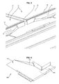
figure 1 est un schéma représentant en vue de perspective un dispositif d'intégration d'une pluralité de panneaux solaires, montés sur les liteaux du toit, en l'absence de panneaux solaires ; - la
figure 2 est un schéma en vue de perspective d'un raccord supérieur du dispositif d'intégration de lafigure 1 ; - la
figure 3 est un schéma en vue de perspective du raccord supérieur de lafigure 2 , une fois installée entre deux parties supérieures de deux panneaux solaires ; - la
figure 4 est un schéma en vue de perspective d'un premier type de raccord d'angle du dispositif d'intégration, destiné à être mis en place au niveau d'un angle supérieur, en l'occurrence d'un angle supérieur gauche, dudit dispositif ; - la
figure 5 est un schéma en vue de perspective d'un raccord d'angle du type de celui illustré sur lafigure 4 , une fois installé en l'occurrence au niveau d'un angle supérieur droit du dispositif ; - la
figure 6 est une vue élargie de la vue illustrée sur lafigure 2 , et sur laquelle on peut distinguer à la fois des raccords supérieur et un raccord d'angle montés sur des panneaux solaires ; - la
figure 7 est un schéma selon une vue de perspective d'un couvercle du dispositif d'intégration ; - la
figure 8 est une vue en perspective du couvercle illustré sur lafigure 7 , une fois installé sur un panneau solaire ; - la
figure 9 est un schéma en vue de perspective d'un raccord inférieur du dispositif d'intégration ; - la
figure 10 est une représentation, en vue de perspective d'un second type de raccord d'angle du dispositif d'intégration, destiné à être mis en place au niveau d'un angle inférieur, en l'occurrence d'un angle inférieur gauche, dudit dispositif ; - la
figure 11 est une représentation en vue de perspective d'un montage comprenant un raccord inférieur monté entre deux panneaux solaires, et un raccord d'angle monté sur l'un des deux panneaux ; - la
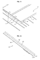
figure 12 est une vue en perspective d'un couloir latéral, en l'occurrence d'un couloir gauche, du dispositif d'intégration ; - la
figure 13 est une représentation d'un couloir latéral droit, une fois installé sur un panneau solaire, et avec un raccord d'angle et un raccord inférieur.
- the
figure 1 is a diagram showing for perspective a device for integrating a plurality of solar panels, mounted on the roof battens, in the absence of solar panels; - the
figure 2 is a schematic perspective view of a top fitting of the device integrating thefigure 1 ; - the
figure 3 is a schematic perspective view of the top fitting of thefigure 2 once installed between two upper parts of two solar panels; - the
figure 4 is a perspective view of a first type of corner fitting of the integration device, intended to be placed at a higher angle, in this case a left upper angle, of said device ; - the
figure 5 is a schematic perspective view of a corner fitting of the type shown in thefigure 4 once installed in this case at a higher right angle of the device; - the
figure 6 is an enlarged view of the illustrated view on thefigure 2 , and on which can be distinguished both top connectors and an angle fitting mounted on solar panels; - the
figure 7 is a diagram according to a perspective view of a cover of the integration device; - the
figure 8 is a perspective view of the lid shown on thefigure 7 once installed on a solar panel; - the
figure 9 is a perspective view of a lower connection of the integration device; - the
figure 10 is a perspective view of a second type of corner fitting of the integration device, intended to be placed at a lower angle, in this case a lower left corner, of said device; - the
figure 11 is a perspective view of an assembly comprising a lower connector mounted between two solar panels, and a corner fitting mounted on one of the two panels; - the
figure 12 is a perspective view of a lateral corridor, in this case a left lane, of the integration device; - the
figure 13 is a representation of a straight lateral corridor, once installed on a solar panel, and with a corner connection and a lower connection.
Le dispositif d'intégration d'une pluralité de panneaux solaires sur un toit comprend un raccord supérieur 100 entre la partie supérieure 11 d'un panneau solaire (10) et le toit, un raccord inférieur 200 entre la partie inférieure 12 du panneau solaire et le toit, et un couloir central 600.The device for integrating a plurality of solar panels on a roof comprises an
Chaque panneau solaire présentant un châssis 15, le raccord supérieur 100 de forme symétrique est agencé de sorte qu'il assure le raccordement avec deux châssis 15 de panneaux solaires disposés l'un à côté de l'autre, sur une demi-largeur supérieure desdits châssis.Each solar panel having a
Le raccord inférieur 200 de forme symétrique est quant à lui agencé de sorte qu'il assure le raccordement avec les deux mêmes châssis, sur une demi-largeur inférieure desdits châssis.The
Le couloir central 600 est quant à lui agencé en forme de U pour assurer un recouvrement avec le raccord supérieur 100, le raccord inférieur 200 et les deux châssis 15 disposés l'un à côté de l'autre. Le couloir central 600 est donc situé en sandwich entre ces deux châssis et s'étend selon la hauteur de ceux-ci. Chacun des rebords 611, 612 du couloir central 600 présente une hauteur et une forme adaptées pour venir en prise avec une lamelle 17, 18 fixée sur le côté de châssis de panneau solaire attenant (
Le raccord supérieur 100 comprend par ailleurs un couloir 110 agencé en forme de U (section en U) dont les côtés ou rebords 111, 112 forment respectivement une butée latérale à l'un des deux châssis de panneau solaire entre lesquels le couloir est disposé. Ces côtés 111, 112 sont par ailleurs agencés pour venir en prise avec une lamelle de section droite fixée sur le côté du châssis. A cet effet ils présentent donc une forme permettant cet agencement. (hauteur, épaisseur, partie supérieure plane).The
Le raccord supérieur 100 comprend également deux butées supérieures 120, 130 agencées pour venir en appui contre la face arrière d'un des deux châssis. A cet effet, ils sont disposés symétriquement et perpendiculairement par rapport à l'axe du couloir 110. Le châssis d'un panneau solaire est donc correctement maintenu au niveau de ses coins (
Le raccord supérieur 100 comprend aussi une partie plane 140 comportant un rebord 150 s'étendant perpendiculairement par rapport à la partie plane 140 et selon la direction de la longueur du raccord supérieur 100, et présentant une hauteur H prédéterminée pour maintenir en position des tuiles du toit directement attenantes au raccord supérieur 100. En l'absence d'une telle pièce 150, la rangée de tuiles au contact du dispositif ne serait pas dans l'alignement du toit et des problèmes d'étanchéité et d'esthétique générale seraient rencontrés (
Le raccord inférieur 200 comprend un couloir 210 agencé en forme de U dont les côtés ou rebords 211, 212 forment respectivement des butées latérales à l'un des deux châssis de panneau solaire entre lesquels ce couloir 210 est disposé. Ces côtés 211, 212 présentent une forme adaptée (hauteur, épaisseur, partie supérieure plane) pour venir en prise avec une lamelle 17, 18 de section droite fixée sur le côté correspondant du châssis 15 (
Le raccord inférieur 200 comprend également deux butées inférieures 220, 230 disposées symétriquement et perpendiculairement par rapport à l'axe du couloir 210, de longueur adaptée à la demi-largeur d'un châssis. Ces butées 220, 230 présentent une forme adaptée (hauteur, épaisseur, partie supérieure plane) pour venir en prise avec une lamelle 19 de section droite fixée sur la face avant du châssis correspondant (
Les lamelles 17, 18, 19 sont fixées par tous moyens adaptés sur le châssis de sorte qu'il existe un jour 170 entre celles-ci et le châssis.The
Le dispositif comprend aussi des raccords d'angles 500, 700 qui permettent de raccorder un couloir latéral (qui sera décrit ultérieurement), le châssis de panneau solaire, tant sur le côté de celui-ci que sur sa partie supérieure, et ce de manière analogue au raccord supérieur 100. On distingue à cet effet deux types de raccords d'angles.The device also comprises
Les premiers raccords d'angles 500 comportent une première partie 510 agencée pour assurer le raccordement avec une demi-largeur supérieure d'un châssis et une deuxième partie 520, perpendiculaire à la première partie 510, agencée en forme de couloir à section en U pour venir en prise avec une lamelle 17 fixée sur le côté du châssis (
Les seconds raccords d'angles 700 comportent une première partie 710 agencée pour assurer le raccordement avec une demi-largeur inférieure d'un châssis et une deuxième partie 720, perpendiculaire à la première partie 710, agencée en forme de couloir à section en U pour venir en prise avec une lamelle 17 fixée sur le côté du châssis (
La première partie 710 d'un second raccord d'angle 700 est également agencée pour venir en prise avec une lamelle 19 de section droite fixée sur la face avant du châssis.The
Avec cet agencement, le châssis 15 et les raccords d'angle 500, 700 sont parfaitement maintenus ensemble, ce qui permet d'assurer une bonne étanchéité.With this arrangement, the
Le couvercle 800 comprend des moyens d'emboîtement 810 avec un châssis 15 de panneau solaire. Ces moyens d'emboîtement 810 comprennent une butée 811 et un guide 812, 813 à chacune des extrémités de la butée 810 s'étendant perpendiculairement par rapport à la butée 810. Ces moyens d'emboîtement 810 présentent donc une section en forme de U, destinée à recevoir la partie supérieure du châssis 15 du panneau solaire 10. A cet effet, les moyens d'emboîtement présentent une longueur adaptée à la largeur du châssis 15 du panneau solaire.The
Les moyens d'emboîtement 810 du couvercle comprennent également une agrafe 814 s'étendant dans le prolongement de la butée 810, sur toute la longueur de celle-ci (
La section de cette agrafe 814 est agencée pour venir en prise avec une lamelle 16 de section droite fixée sur la partie supérieure du châssis 15 du panneau solaire 10, tout en recouvrant cette lamelle 16 pour l'étanchéité. A cet effet, la lamelle 16 est fixée sur le châssis de sorte qu'il existe un jour entre cette lamelle 16 et le panneau solaire (
L'agrafe 814 permet de protéger la face supérieure de la partie supérieure du châssis 15, ce qui renforce l'étanchéité. La présence de cette agrafe 814, en combinaison avec la lamelle 16 fixée sur le panneau solaire, est particulièrement bien adaptée pour assurer une étanchéité pour des pentes faibles du toit, c'est-à-dire typiquement comprises entre 10° et 30°, et améliore également l'aspect esthétique de l'intégration du panneau solaire 10 sur le toit.The
Par ailleurs, le couvercle 800 est disposé en vis-à-vis d'un châssis de panneau solaire, contrairement aux raccords supérieurs 100 qui protègent, sur une demi-largeur de châssis, deux châssis de panneaux solaires. Le couvercle 800 est ainsi monté de manière décalée au-dessus de deux moitiés de raccords supérieurs 100. Une telle disposition participe à maintenir correctement en place les raccords supérieurs et améliore l'étanchéité du dispositif.Furthermore, the
Le couvercle 800 comprend une partie plane 815 comportant un rebord 816 s'étendant perpendiculairement par rapport à la partie plane 815 et selon la direction de la longueur du couvercle 800, et présentant une hauteur H prédéterminée pour maintenir en position des tuiles du toit directement attenantes au couvercle 800.The
Les couloirs latéraux 300, 400 sont agencés pour assurer le raccordement étanche avec les parties latérales de châssis de panneaux solaires. Plus précisément, chaque couloir 300, 400 de section en forme de U est agencé d'une part pour assurer un recouvrement avec les premiers et seconds raccords d'angles 500, 700 et d'autre part venir en prise avec une lamelle 17, 18 de section droite fixée sur le côté du châssis correspondant.The
Les couloirs 300, 400 ainsi que les raccords supérieur 100 et inférieur 200 et le couvercle 800 présentent une largeur suffisante pour recouvrir suffisamment les éléments de toit attenants au panneau solaire, et ce pour assurer une étanchéité parfaite.The
Par ailleurs, il est prévu pour les couloirs 300, 400 des replis 301, 401. Ces replis 301, 401 ont une fonction de butée pour les tuiles attenantes.Furthermore, it is planned for the
Les replis 301, 401 des couloirs 300, 400 sont particulièrement bien adaptés à la gamme de tuiles « Grands Moules du Sud », et encore plus particulièrement aux tuiles dites Romane Canal.The
En effet, au niveau du couloir gauche 300, le montage est tel que l'extrémité droite de la partie galbée de la tuile de type « Grands Moules du Sud » vienne en butée sur la partie externe du repli 301 du couloir gauche 300, la partie plane de la tuile en continuité de cette partie galbée venant s'insérer au-dessous de la première partie 320 du couloir 300.Indeed, at the level of the
Et, au niveau du couloir droit 400, le montage est tel que l'extrémité gauche de la partie galbée vient en prise avec le repli 401 à l'intérieur du couloir 400.And, at the
La première partie 320, 420 des couloirs 300, 400 présente une largeur plus importante que les couloirs classiques, à savoir une largeur I1 de l'ordre de 4cm, alors que typiquement la largeur des couloirs est de l'ordre de 3cm. Ceci est particulièrement bien adapté aux contraintes des toits à pente faible, cette largeur permettant d'augmenter le débit d'eau susceptible de s'écouler sur ces couloirs 300, 400. Accessoirement, cela évite que des feuilles viennent se coincer dans les couloirs. Les couloirs jouent ici un rôle de gouttières, vers lesquels l'eau est redirigée au moyen des éléments 160, 170 et 530.The
La deuxième partie ou rebord 330, 430 est quant à elle destinée à être plaquée contre le panneau solaire, de sorte qu'il n'existe aucun jour entre celle-ci et le panneau solaire pour assurer une bonne étanchéité. A cet effet, les rebords 330, 430 sont agencées (épaisseur, hauteur) pour venir en prise avec une lamelle, de section droite, fixée sur le côté d'un châssis.The second part or
Une possibilité de raccordement entre le raccord inférieur 200 et la partie de toit qui lui est attenante est d'utiliser une bavette en Plomb. Cette bavette est disposée sur l'extrémité de la partie galbée de la tuile et vient coopérer avec un rebord incurvé 240 du raccord inférieur 200 pour assurer l'étanchéité.A possibility of connection between the
Une autre possibilité pour assurer le raccord étanche entre le raccord inférieur 200 et le toit, est d'utiliser des tuiles spécialement conçues. Ces tuiles spécialement conçues (non illustrées) font l'objet d'un brevet spécifique de la demanderesse.Another possibility for ensuring the watertight connection between the
Celles-ci, de type tuile à emboîtement, comportent au moins une partie galbée, une partie d'extrémité plane, de largeur comprise entre 100 et 140mm, dans le prolongement supérieur de la partie galbée, la partie d'extrémité plane comprenant au moins une goulotte s'étendant sur toute la largeur de ladite partie plane.These, of the interlocking tile type, comprise at least one curved part, a flat end portion, with a width of between 100 and 140 mm, in the upper extension of the curved part, the flat end portion comprising at least a chute extending over the entire width of said planar portion.
Dans ce cas, chacune de ces tuiles est donc disposée en partie basse de l'ensemble formé par le dispositif selon l'invention et le panneau solaire.In this case, each of these tiles is arranged in the lower part of the assembly formed by the device according to the invention and the solar panel.
Cette solution ne nécessite pas l'installation d'une bavette en Plomb, ce qui permet une installation plus rapide.This solution does not require the installation of a lead flap, which allows a faster installation.
L'invention concerne également un ensemble comprenant un dispositif tel que décrit ci-dessus et une pluralité de panneaux solaires 10, en particulier de type solaire thermique, comportant chacun un châssis 15 comprenant une première lamelle 16 fixée sur la face supérieure du châssis 15 de sorte qu'il existe un jour entre cette lamelle 16 et le panneau solaire ; et une deuxième lamelle 19 fixée sur la face avant du châssis de sorte qu'il existe un jour entre cette lamelle et la face avant du châssis.The invention also relates to an assembly comprising a device as described above and a plurality of
Cet ensemble comprend encore une troisième lamelle 17 fixée sur le côté gauche du châssis de sorte qu'il existe un jour entre cette lamelle et le côté gauche du châssis ; et une quatrième lamelle 18 fixée sur le côté droit du châssis de sorte qu'il existe un jour entre cette lamelle et le côté droit du châssis.This assembly further comprises a
L'invention concerne encore un toit comprenant un ensemble comme décrit ci-dessus, et comportant une pluralité de tuiles de type Grands Moules du Sud dont l'extrémité droite de la partie galbée est en butée contre la partie externe d'un repli 301 du couloir latéral gauche 300 de l'ensemble.The invention further relates to a roof comprising an assembly as described above, and comprising a plurality of tiles of the South Big Mussel type whose right end of the curved portion abuts against the outer portion of a
Le toit pourra comprendre une pluralité de tuiles de type Grands Moules du Sud dont l'extrémité gauche de la partie galbée vient en prise avec un repli 401 à l'intérieur du couloir latéral droit 400 de l'ensemble.The roof may include a plurality of tiles of the type Southern Big Mussels whose left end of the curved portion engages a
Le toit pourra encore comprendre une pluralité de tuiles, de type tuile à emboîtement, disposées en partie basse desdits ensembles, chaque tuile comportant au moins une partie galbée et une partie d'extrémité plane dans le prolongement supérieur de la partie galbée, la partie d'extrémité plane, d'une largeur comprise entre 100mm et 140mm étant recouverte par le raccord inférieur 200.The roof may further comprise a plurality of interlocking tiles, arranged at the bottom of said sets, each tile having at least one curved portion and a flat end portion in the upper extension of the curved portion, the portion of flat end, a width between 100mm and 140mm being covered by the
Le dispositif selon l'invention présente donc de nombreux avantages.The device according to the invention therefore has many advantages.
Le dispositif selon l'invention permet d'intégrer au mieux le panneau solaire 10 au toit, notamment le panneau solaire thermique, par des moyens épousant la forme du panneau.The device according to the invention makes it possible to better integrate the
De plus, le temps de pose est réduit, car le dispositif est pensé pour un montage rapide, facile :
- le dispositif peut être monté par simple pose et emboîtement de moyens complémentaires des différentes pièces le composant, chacune de ces pièces étant par ailleurs fixées sur les liteaux de la toiture ;
- la modularité est optimisée pour toutes les configurations d'assemblage en prévoyant des pièces de conception spécifiques ;
- si le dispositif est adapté à la famille de tuiles « Grands Moules du Sud », son montage est encore plus aisé pour les tuiles dénommées Romane Canal par la demanderesse, le choix dans les dimensions du dispositif étant particulièrement bien adapté à cette tuile ;
- le dispositif reste adapté à tout type de tuiles galbées, dont le galbe peut aller jusqu'à 140mm, voire au-delà (le galbe d'une Romane Canal étant de l'ordre de 120mm).
- the device can be mounted by simple installation and interlocking complementary means of the various parts of the component, each of these parts being also fixed on the battens of the roof;
- modularity is optimized for all assembly configurations by providing specific design parts;
- if the device is adapted to the family of tiles "Grands Moules du Sud", its assembly is even easier for the tiles called Romane Canal by the plaintiff, the choice in the dimensions of the device being particularly well suited to this tile;
- the device remains adapted to any type of curved tiles, whose curvature can go up to 140mm, or even beyond (the curve of a Canal Romane being of the order of 120mm).
Enfin, l'étanchéité est assurée par de nombreux moyens :
- une barrière multiple est prévue au niveau de la jonction entre les panneaux, par le biais du raccord supérieur 100 et du couvercle 800 qui sont disposés de manière décalée, ce qui permet de renforcer l'étanchéité au niveau de cette jonction ;
- une adaptation de la partie basse du dispositif, particulièrement bien adapté avec une tuile de type Romane Canal de conception spécifique, en évitant l'usage d'une bavette (généralement en Plomb).
- a multiple barrier is provided at the junction between the panels, through the
upper connector 100 and thecover 800 which are arranged in an offset manner, which reinforces the seal at this junction; - an adaptation of the lower part of the device, particularly well suited with a Romane Canal tile type specific design, avoiding the use of a flap (usually lead).
Enfin, on note que les solutions proposées, ici sont particulièrement bien adaptées à des toits dont la pente est comprise entre 10 et 30°.Finally, we note that the proposed solutions, here are particularly well suited to roofs whose slope is between 10 and 30 °.
On comprend cependant que le dispositif selon l'invention peut tout à fait s'adapter à tout type de panneau solaire. Il suffit pour cela d'y monter des moyens comme les lamelles 16, 17, 18, 19 ou tout autre moyen proposant une fonction équivalente.However, it is understood that the device according to the invention can quite adapt to any type of solar panel. It suffices for it to mount means such as the
Claims (16)
Applications Claiming Priority (1)
| Application Number | Priority Date | Filing Date | Title |
|---|---|---|---|
| FR0757468A FR2920800A1 (en) | 2007-09-10 | 2007-09-10 | DEVICE FOR INTEGRATING SOLAR PANEL ON A ROOF |
Publications (2)
| Publication Number | Publication Date |
|---|---|
| EP2034249A1 true EP2034249A1 (en) | 2009-03-11 |
| EP2034249B1 EP2034249B1 (en) | 2013-06-12 |
Family
ID=39201874
Family Applications (1)
| Application Number | Title | Priority Date | Filing Date |
|---|---|---|---|
| EP08164011.2A Active EP2034249B1 (en) | 2007-09-10 | 2008-09-10 | Installation comprising a plurality of solar panels and device for integrating the panels on a roof |
Country Status (2)
| Country | Link |
|---|---|
| EP (1) | EP2034249B1 (en) |
| FR (1) | FR2920800A1 (en) |
Cited By (7)
| Publication number | Priority date | Publication date | Assignee | Title |
|---|---|---|---|---|
| EP2295893A1 (en) * | 2009-04-01 | 2011-03-16 | Producciones Mitjavila, S.A. | Modular system for fixing solar panels to a roof including means for channelling water |
| FR2955131A1 (en) * | 2010-01-14 | 2011-07-15 | Solar And Co | Solar panel fixing system for roof, has gutters arranged to form solar panel frame receiving chassis that is defined by bottom walls of gutters and inner side walls of gutters, where side walls form lateral adjustment belt of frame of panel |
| EP2434230A2 (en) | 2010-09-24 | 2012-03-28 | ENERGY RESOURCES S.p.a. | Supporting and fixing structure for flat panels or photovoltaic modules in coplanar position, and that allows the water to be drained off |
| EP2282141A3 (en) * | 2009-06-23 | 2013-08-21 | ALTEC Solartechnik AG | In-roof solar collector fitting assembly |
| FR3002620A1 (en) * | 2013-02-27 | 2014-08-29 | Terreal | Device for integrating thermal solar panel on inclined roof, has front and rear transverse walls, where upper surface of panel has edge that is folded back to bottom and arranged at distance from longitudinal and transverse walls |
| EP2533300A3 (en) * | 2011-06-08 | 2014-10-08 | Dietrich Rieth | Solar roof |
| US10505492B2 (en) | 2016-02-12 | 2019-12-10 | Solarcity Corporation | Building integrated photovoltaic roofing assemblies and associated systems and methods |
Citations (6)
| Publication number | Priority date | Publication date | Assignee | Title |
|---|---|---|---|---|
| DE9201273U1 (en) | 1992-02-03 | 1992-05-07 | Dorfmueller, Joachim, 7000 Stuttgart, De | |
| DE29521277U1 (en) | 1995-05-30 | 1996-11-07 | Viessmann Werke Kg | Solar panel |
| WO2000012839A1 (en) | 1998-08-31 | 2000-03-09 | Pacific Solar Pty. Ltd. | Panel mounting frame and method |
| WO2004035954A2 (en) | 2002-10-17 | 2004-04-29 | Michel Yermakoff | Device for fixing solar panels |
| DE10321422A1 (en) | 2003-05-12 | 2005-01-27 | PRIMA Bau- und Dämmsysteme Ges. m.b.H. & Co. KG | Solar collector consists of frame sections connected via corner connectors with passages and bores for assembly and installation |
| US20050217665A1 (en) | 2004-03-30 | 2005-10-06 | Luconi Gregg F | Solar collector mounting array |
Family Cites Families (1)
| Publication number | Priority date | Publication date | Assignee | Title |
|---|---|---|---|---|
| DE7829553U1 (en) * | 1978-10-04 | 1979-01-18 | Stiebel Eltron Gmbh & Co Kg, 3450 Holzminden | MOUNTING FRAME FOR SOLAR COLLECTORS |
-
2007
- 2007-09-10 FR FR0757468A patent/FR2920800A1/en not_active Withdrawn
-
2008
- 2008-09-10 EP EP08164011.2A patent/EP2034249B1/en active Active
Patent Citations (6)
| Publication number | Priority date | Publication date | Assignee | Title |
|---|---|---|---|---|
| DE9201273U1 (en) | 1992-02-03 | 1992-05-07 | Dorfmueller, Joachim, 7000 Stuttgart, De | |
| DE29521277U1 (en) | 1995-05-30 | 1996-11-07 | Viessmann Werke Kg | Solar panel |
| WO2000012839A1 (en) | 1998-08-31 | 2000-03-09 | Pacific Solar Pty. Ltd. | Panel mounting frame and method |
| WO2004035954A2 (en) | 2002-10-17 | 2004-04-29 | Michel Yermakoff | Device for fixing solar panels |
| DE10321422A1 (en) | 2003-05-12 | 2005-01-27 | PRIMA Bau- und Dämmsysteme Ges. m.b.H. & Co. KG | Solar collector consists of frame sections connected via corner connectors with passages and bores for assembly and installation |
| US20050217665A1 (en) | 2004-03-30 | 2005-10-06 | Luconi Gregg F | Solar collector mounting array |
Cited By (7)
| Publication number | Priority date | Publication date | Assignee | Title |
|---|---|---|---|---|
| EP2295893A1 (en) * | 2009-04-01 | 2011-03-16 | Producciones Mitjavila, S.A. | Modular system for fixing solar panels to a roof including means for channelling water |
| EP2282141A3 (en) * | 2009-06-23 | 2013-08-21 | ALTEC Solartechnik AG | In-roof solar collector fitting assembly |
| FR2955131A1 (en) * | 2010-01-14 | 2011-07-15 | Solar And Co | Solar panel fixing system for roof, has gutters arranged to form solar panel frame receiving chassis that is defined by bottom walls of gutters and inner side walls of gutters, where side walls form lateral adjustment belt of frame of panel |
| EP2434230A2 (en) | 2010-09-24 | 2012-03-28 | ENERGY RESOURCES S.p.a. | Supporting and fixing structure for flat panels or photovoltaic modules in coplanar position, and that allows the water to be drained off |
| EP2533300A3 (en) * | 2011-06-08 | 2014-10-08 | Dietrich Rieth | Solar roof |
| FR3002620A1 (en) * | 2013-02-27 | 2014-08-29 | Terreal | Device for integrating thermal solar panel on inclined roof, has front and rear transverse walls, where upper surface of panel has edge that is folded back to bottom and arranged at distance from longitudinal and transverse walls |
| US10505492B2 (en) | 2016-02-12 | 2019-12-10 | Solarcity Corporation | Building integrated photovoltaic roofing assemblies and associated systems and methods |
Also Published As
| Publication number | Publication date |
|---|---|
| EP2034249B1 (en) | 2013-06-12 |
| FR2920800A1 (en) | 2009-03-13 |
Similar Documents
| Publication | Publication Date | Title |
|---|---|---|
| EP2034249B1 (en) | Installation comprising a plurality of solar panels and device for integrating the panels on a roof | |
| FR2916464A1 (en) | Solar panel i.e. thermal solar panel, integrating device for roof of building, has chutes comprising fitting units that are complementary to and fitted by clipping with corresponding fitting units of upper and lower connections | |
| FR2923236A1 (en) | SEALING ELEMENT FOR PANEL CHASSIS AND CORRESPONDING SYSTEM | |
| EP3336447A1 (en) | Panel-supporting device | |
| FR2918397A1 (en) | DEVICE FOR INTEGRATING SOLAR PANEL ON A ROOF, PARTICULARLY FOR PHOTOVOLTAIC SOLAR. | |
| CA3057596A1 (en) | Glazing comprising a clip-on profiled bead for a clip-on cover part | |
| FR2996237A1 (en) | Panel i.e. sandwich panel, for e.g. flat roof, has groove uniformly tilted relative to outer surface of panel and receiving junction device that forms throat, where interior surface of panel is formed opposite to outer surface | |
| EP2144016A1 (en) | Support structure for a solar panel on a construction surface | |
| FR2813624A1 (en) | Connecting/sealing extrusion for edge of sandwich panel used for wall facings or partitions has joint surface with tongue, groove and seals | |
| EP2589723A1 (en) | Device for covering a section of a suspended construction element | |
| FR2956681A1 (en) | Photovoltaic panels positioning and securing device for use on e.g. main rafters of building i.e. house, has inverse U-shaped central part comprising flat base supporting edge of one of panels or two edges of two juxtaposed panels | |
| EP3553945B1 (en) | Nesting tile and associated roof assembly | |
| FR2952663A1 (en) | MECHANICAL HOLDING PROFILES AND RECOVERY OF MODULES | |
| EP0791700A1 (en) | Fastening holder plate and spacer for obtaining claddings in the field of construction, and claddings so obtained | |
| EP2491837A1 (en) | Shower cubicle with panels assembled by fitting | |
| BE1003499A6 (en) | IMPROVEMENTS IN AND CONCERNING WINDOWS. | |
| EP1054118B1 (en) | Misalignment-tolerant corner piece for connecting two adjoining angle sections of a plinth or similar | |
| FR3101098A1 (en) | Sliding shutter locking system. | |
| EP1985791B1 (en) | Metal slat for roller shutters or sectional gates | |
| EP2551417B1 (en) | Curtain wall with air-sealing device | |
| EP2722457B1 (en) | Roof extension equipment | |
| FR2970016A1 (en) | Device for ventilating space defined under photovoltaic panels in inclined roof of e.g. private building, has upper portion connected to front portion via articulated connections that allow angular clearance between front and upper portions | |
| FR3085290A1 (en) | SCREW BOX FOR FIXING BLADES OF A TERRACE FLOOR | |
| FR2967433A1 (en) | Device for fixing photovoltaic panels on carcass of roof of house, has locking elements mounted on fixation frames and associated with sealing elements that assure sealing between photovoltaic panels received by housings of frames | |
| FR2976007A1 (en) | MODULAR COVER DEVICE |
Legal Events
| Date | Code | Title | Description |
|---|---|---|---|
| PUAI | Public reference made under article 153(3) epc to a published international application that has entered the european phase |
Free format text: ORIGINAL CODE: 0009012 |
|
| AK | Designated contracting states |
Kind code of ref document: A1 Designated state(s): AT BE BG CH CY CZ DE DK EE ES FI FR GB GR HR HU IE IS IT LI LT LU LV MC MT NL NO PL PT RO SE SI SK TR |
|
| AX | Request for extension of the european patent |
Extension state: AL BA MK RS |
|
| 17P | Request for examination filed |
Effective date: 20090702 |
|
| AKX | Designation fees paid |
Designated state(s): AT BE BG CH CY CZ DE DK EE ES FI FR GB GR HR HU IE IS IT LI LT LU LV MC MT NL NO PL PT RO SE SI SK TR |
|
| 17Q | First examination report despatched |
Effective date: 20100617 |
|
| RIC1 | Information provided on ipc code assigned before grant |
Ipc: F24J 2/46 20060101ALI20120919BHEP Ipc: F24J 2/52 20060101ALI20120919BHEP Ipc: F24J 2/04 20060101AFI20120919BHEP |
|
| GRAP | Despatch of communication of intention to grant a patent |
Free format text: ORIGINAL CODE: EPIDOSNIGR1 |
|
| GRAS | Grant fee paid |
Free format text: ORIGINAL CODE: EPIDOSNIGR3 |
|
| GRAA | (expected) grant |
Free format text: ORIGINAL CODE: 0009210 |
|
| AK | Designated contracting states |
Kind code of ref document: B1 Designated state(s): AT BE BG CH CY CZ DE DK EE ES FI FR GB GR HR HU IE IS IT LI LT LU LV MC MT NL NO PL PT RO SE SI SK TR |
|
| REG | Reference to a national code |
Ref country code: GB Ref legal event code: FG4D Free format text: NOT ENGLISH |
|
| REG | Reference to a national code |
Ref country code: CH Ref legal event code: EP |
|
| REG | Reference to a national code |
Ref country code: AT Ref legal event code: REF Ref document number: 616840 Country of ref document: AT Kind code of ref document: T Effective date: 20130615 |
|
| REG | Reference to a national code |
Ref country code: IE Ref legal event code: FG4D Free format text: LANGUAGE OF EP DOCUMENT: FRENCH |
|
| REG | Reference to a national code |
Ref country code: DE Ref legal event code: R096 Ref document number: 602008025256 Country of ref document: DE Effective date: 20130808 |
|
| PG25 | Lapsed in a contracting state [announced via postgrant information from national office to epo] |
Ref country code: NO Free format text: LAPSE BECAUSE OF FAILURE TO SUBMIT A TRANSLATION OF THE DESCRIPTION OR TO PAY THE FEE WITHIN THE PRESCRIBED TIME-LIMIT Effective date: 20130912 Ref country code: LT Free format text: LAPSE BECAUSE OF FAILURE TO SUBMIT A TRANSLATION OF THE DESCRIPTION OR TO PAY THE FEE WITHIN THE PRESCRIBED TIME-LIMIT Effective date: 20130612 Ref country code: SE Free format text: LAPSE BECAUSE OF FAILURE TO SUBMIT A TRANSLATION OF THE DESCRIPTION OR TO PAY THE FEE WITHIN THE PRESCRIBED TIME-LIMIT Effective date: 20130612 Ref country code: GR Free format text: LAPSE BECAUSE OF FAILURE TO SUBMIT A TRANSLATION OF THE DESCRIPTION OR TO PAY THE FEE WITHIN THE PRESCRIBED TIME-LIMIT Effective date: 20130913 Ref country code: SI Free format text: LAPSE BECAUSE OF FAILURE TO SUBMIT A TRANSLATION OF THE DESCRIPTION OR TO PAY THE FEE WITHIN THE PRESCRIBED TIME-LIMIT Effective date: 20130612 Ref country code: ES Free format text: LAPSE BECAUSE OF FAILURE TO SUBMIT A TRANSLATION OF THE DESCRIPTION OR TO PAY THE FEE WITHIN THE PRESCRIBED TIME-LIMIT Effective date: 20130923 Ref country code: FI Free format text: LAPSE BECAUSE OF FAILURE TO SUBMIT A TRANSLATION OF THE DESCRIPTION OR TO PAY THE FEE WITHIN THE PRESCRIBED TIME-LIMIT Effective date: 20130612 |
|
| REG | Reference to a national code |
Ref country code: AT Ref legal event code: MK05 Ref document number: 616840 Country of ref document: AT Kind code of ref document: T Effective date: 20130612 |
|
| REG | Reference to a national code |
Ref country code: NL Ref legal event code: VDEP Effective date: 20130612 |
|
| REG | Reference to a national code |
Ref country code: LT Ref legal event code: MG4D |
|
| PG25 | Lapsed in a contracting state [announced via postgrant information from national office to epo] |
Ref country code: HR Free format text: LAPSE BECAUSE OF FAILURE TO SUBMIT A TRANSLATION OF THE DESCRIPTION OR TO PAY THE FEE WITHIN THE PRESCRIBED TIME-LIMIT Effective date: 20130612 Ref country code: BG Free format text: LAPSE BECAUSE OF FAILURE TO SUBMIT A TRANSLATION OF THE DESCRIPTION OR TO PAY THE FEE WITHIN THE PRESCRIBED TIME-LIMIT Effective date: 20130912 |
|
| PG25 | Lapsed in a contracting state [announced via postgrant information from national office to epo] |
Ref country code: LV Free format text: LAPSE BECAUSE OF FAILURE TO SUBMIT A TRANSLATION OF THE DESCRIPTION OR TO PAY THE FEE WITHIN THE PRESCRIBED TIME-LIMIT Effective date: 20130612 |
|
| PG25 | Lapsed in a contracting state [announced via postgrant information from national office to epo] |
Ref country code: CZ Free format text: LAPSE BECAUSE OF FAILURE TO SUBMIT A TRANSLATION OF THE DESCRIPTION OR TO PAY THE FEE WITHIN THE PRESCRIBED TIME-LIMIT Effective date: 20130612 Ref country code: IS Free format text: LAPSE BECAUSE OF FAILURE TO SUBMIT A TRANSLATION OF THE DESCRIPTION OR TO PAY THE FEE WITHIN THE PRESCRIBED TIME-LIMIT Effective date: 20131012 Ref country code: SK Free format text: LAPSE BECAUSE OF FAILURE TO SUBMIT A TRANSLATION OF THE DESCRIPTION OR TO PAY THE FEE WITHIN THE PRESCRIBED TIME-LIMIT Effective date: 20130612 Ref country code: AT Free format text: LAPSE BECAUSE OF FAILURE TO SUBMIT A TRANSLATION OF THE DESCRIPTION OR TO PAY THE FEE WITHIN THE PRESCRIBED TIME-LIMIT Effective date: 20130612 Ref country code: EE Free format text: LAPSE BECAUSE OF FAILURE TO SUBMIT A TRANSLATION OF THE DESCRIPTION OR TO PAY THE FEE WITHIN THE PRESCRIBED TIME-LIMIT Effective date: 20130612 Ref country code: PT Free format text: LAPSE BECAUSE OF FAILURE TO SUBMIT A TRANSLATION OF THE DESCRIPTION OR TO PAY THE FEE WITHIN THE PRESCRIBED TIME-LIMIT Effective date: 20131014 |
|
| PG25 | Lapsed in a contracting state [announced via postgrant information from national office to epo] |
Ref country code: PL Free format text: LAPSE BECAUSE OF FAILURE TO SUBMIT A TRANSLATION OF THE DESCRIPTION OR TO PAY THE FEE WITHIN THE PRESCRIBED TIME-LIMIT Effective date: 20130612 Ref country code: RO Free format text: LAPSE BECAUSE OF FAILURE TO SUBMIT A TRANSLATION OF THE DESCRIPTION OR TO PAY THE FEE WITHIN THE PRESCRIBED TIME-LIMIT Effective date: 20130612 Ref country code: NL Free format text: LAPSE BECAUSE OF FAILURE TO SUBMIT A TRANSLATION OF THE DESCRIPTION OR TO PAY THE FEE WITHIN THE PRESCRIBED TIME-LIMIT Effective date: 20130612 |
|
| BERE | Be: lapsed |
Owner name: TERREAL Effective date: 20130930 |
|
| PLBE | No opposition filed within time limit |
Free format text: ORIGINAL CODE: 0009261 |
|
| STAA | Information on the status of an ep patent application or granted ep patent |
Free format text: STATUS: NO OPPOSITION FILED WITHIN TIME LIMIT |
|
| PG25 | Lapsed in a contracting state [announced via postgrant information from national office to epo] |
Ref country code: MC Free format text: LAPSE BECAUSE OF FAILURE TO SUBMIT A TRANSLATION OF THE DESCRIPTION OR TO PAY THE FEE WITHIN THE PRESCRIBED TIME-LIMIT Effective date: 20130612 Ref country code: DK Free format text: LAPSE BECAUSE OF FAILURE TO SUBMIT A TRANSLATION OF THE DESCRIPTION OR TO PAY THE FEE WITHIN THE PRESCRIBED TIME-LIMIT Effective date: 20130612 |
|
| REG | Reference to a national code |
Ref country code: CH Ref legal event code: PL |
|
| 26N | No opposition filed |
Effective date: 20140313 |
|
| GBPC | Gb: european patent ceased through non-payment of renewal fee |
Effective date: 20130912 |
|
| PG25 | Lapsed in a contracting state [announced via postgrant information from national office to epo] |
Ref country code: IT Free format text: LAPSE BECAUSE OF FAILURE TO SUBMIT A TRANSLATION OF THE DESCRIPTION OR TO PAY THE FEE WITHIN THE PRESCRIBED TIME-LIMIT Effective date: 20130612 |
|
| REG | Reference to a national code |
Ref country code: DE Ref legal event code: R097 Ref document number: 602008025256 Country of ref document: DE Effective date: 20140313 |
|
| REG | Reference to a national code |
Ref country code: DE Ref legal event code: R119 Ref document number: 602008025256 Country of ref document: DE Effective date: 20140401 |
|
| REG | Reference to a national code |
Ref country code: IE Ref legal event code: MM4A |
|
| PG25 | Lapsed in a contracting state [announced via postgrant information from national office to epo] |
Ref country code: LI Free format text: LAPSE BECAUSE OF NON-PAYMENT OF DUE FEES Effective date: 20130930 Ref country code: GB Free format text: LAPSE BECAUSE OF NON-PAYMENT OF DUE FEES Effective date: 20130912 Ref country code: CH Free format text: LAPSE BECAUSE OF NON-PAYMENT OF DUE FEES Effective date: 20130930 Ref country code: IE Free format text: LAPSE BECAUSE OF NON-PAYMENT OF DUE FEES Effective date: 20130910 Ref country code: BE Free format text: LAPSE BECAUSE OF NON-PAYMENT OF DUE FEES Effective date: 20130930 |
|
| PG25 | Lapsed in a contracting state [announced via postgrant information from national office to epo] |
Ref country code: DE Free format text: LAPSE BECAUSE OF NON-PAYMENT OF DUE FEES Effective date: 20140401 |
|
| PG25 | Lapsed in a contracting state [announced via postgrant information from national office to epo] |
Ref country code: MT Free format text: LAPSE BECAUSE OF FAILURE TO SUBMIT A TRANSLATION OF THE DESCRIPTION OR TO PAY THE FEE WITHIN THE PRESCRIBED TIME-LIMIT Effective date: 20130612 Ref country code: CY Free format text: LAPSE BECAUSE OF FAILURE TO SUBMIT A TRANSLATION OF THE DESCRIPTION OR TO PAY THE FEE WITHIN THE PRESCRIBED TIME-LIMIT Effective date: 20130612 Ref country code: TR Free format text: LAPSE BECAUSE OF FAILURE TO SUBMIT A TRANSLATION OF THE DESCRIPTION OR TO PAY THE FEE WITHIN THE PRESCRIBED TIME-LIMIT Effective date: 20130612 |
|
| PG25 | Lapsed in a contracting state [announced via postgrant information from national office to epo] |
Ref country code: LU Free format text: LAPSE BECAUSE OF NON-PAYMENT OF DUE FEES Effective date: 20130910 Ref country code: HU Free format text: LAPSE BECAUSE OF FAILURE TO SUBMIT A TRANSLATION OF THE DESCRIPTION OR TO PAY THE FEE WITHIN THE PRESCRIBED TIME-LIMIT; INVALID AB INITIO Effective date: 20080910 |
|
| REG | Reference to a national code |
Ref country code: FR Ref legal event code: PLFP Year of fee payment: 9 |
|
| REG | Reference to a national code |
Ref country code: FR Ref legal event code: PLFP Year of fee payment: 10 |
|
| REG | Reference to a national code |
Ref country code: FR Ref legal event code: PLFP Year of fee payment: 11 |
|
| P01 | Opt-out of the competence of the unified patent court (upc) registered |
Effective date: 20230515 |
|
| PGFP | Annual fee paid to national office [announced via postgrant information from national office to epo] |
Ref country code: FR Payment date: 20230809 Year of fee payment: 16 |