EP2033737B1 - Klemmanweisungsverfahren - Google Patents
Klemmanweisungsverfahren Download PDFInfo
- Publication number
- EP2033737B1 EP2033737B1 EP08003578A EP08003578A EP2033737B1 EP 2033737 B1 EP2033737 B1 EP 2033737B1 EP 08003578 A EP08003578 A EP 08003578A EP 08003578 A EP08003578 A EP 08003578A EP 2033737 B1 EP2033737 B1 EP 2033737B1
- Authority
- EP
- European Patent Office
- Prior art keywords
- tool
- axle
- instruction
- clamping
- addition
- Prior art date
- Legal status (The legal status is an assumption and is not a legal conclusion. Google has not performed a legal analysis and makes no representation as to the accuracy of the status listed.)
- Active
Links
Images


Classifications
-
- B—PERFORMING OPERATIONS; TRANSPORTING
- B23—MACHINE TOOLS; METAL-WORKING NOT OTHERWISE PROVIDED FOR
- B23Q—DETAILS, COMPONENTS, OR ACCESSORIES FOR MACHINE TOOLS, e.g. ARRANGEMENTS FOR COPYING OR CONTROLLING; MACHINE TOOLS IN GENERAL CHARACTERISED BY THE CONSTRUCTION OF PARTICULAR DETAILS OR COMPONENTS; COMBINATIONS OR ASSOCIATIONS OF METAL-WORKING MACHINES, NOT DIRECTED TO A PARTICULAR RESULT
- B23Q17/00—Arrangements for observing, indicating or measuring on machine tools
- B23Q17/002—Arrangements for observing, indicating or measuring on machine tools for indicating or measuring the holding action of work or tool holders
- B23Q17/005—Arrangements for observing, indicating or measuring on machine tools for indicating or measuring the holding action of work or tool holders by measuring a force, a pressure or a deformation
-
- B—PERFORMING OPERATIONS; TRANSPORTING
- B23—MACHINE TOOLS; METAL-WORKING NOT OTHERWISE PROVIDED FOR
- B23Q—DETAILS, COMPONENTS, OR ACCESSORIES FOR MACHINE TOOLS, e.g. ARRANGEMENTS FOR COPYING OR CONTROLLING; MACHINE TOOLS IN GENERAL CHARACTERISED BY THE CONSTRUCTION OF PARTICULAR DETAILS OR COMPONENTS; COMBINATIONS OR ASSOCIATIONS OF METAL-WORKING MACHINES, NOT DIRECTED TO A PARTICULAR RESULT
- B23Q1/00—Members which are comprised in the general build-up of a form of machine, particularly relatively large fixed members
- B23Q1/25—Movable or adjustable work or tool supports
- B23Q1/26—Movable or adjustable work or tool supports characterised by constructional features relating to the co-operation of relatively movable members; Means for preventing relative movement of such members
- B23Q1/262—Movable or adjustable work or tool supports characterised by constructional features relating to the co-operation of relatively movable members; Means for preventing relative movement of such members with means to adjust the distance between the relatively slidable members
- B23Q1/265—Movable or adjustable work or tool supports characterised by constructional features relating to the co-operation of relatively movable members; Means for preventing relative movement of such members with means to adjust the distance between the relatively slidable members between rotating members
-
- B—PERFORMING OPERATIONS; TRANSPORTING
- B23—MACHINE TOOLS; METAL-WORKING NOT OTHERWISE PROVIDED FOR
- B23Q—DETAILS, COMPONENTS, OR ACCESSORIES FOR MACHINE TOOLS, e.g. ARRANGEMENTS FOR COPYING OR CONTROLLING; MACHINE TOOLS IN GENERAL CHARACTERISED BY THE CONSTRUCTION OF PARTICULAR DETAILS OR COMPONENTS; COMBINATIONS OR ASSOCIATIONS OF METAL-WORKING MACHINES, NOT DIRECTED TO A PARTICULAR RESULT
- B23Q3/00—Devices holding, supporting, or positioning work or tools, of a kind normally removable from the machine
-
- Y—GENERAL TAGGING OF NEW TECHNOLOGICAL DEVELOPMENTS; GENERAL TAGGING OF CROSS-SECTIONAL TECHNOLOGIES SPANNING OVER SEVERAL SECTIONS OF THE IPC; TECHNICAL SUBJECTS COVERED BY FORMER USPC CROSS-REFERENCE ART COLLECTIONS [XRACs] AND DIGESTS
- Y10—TECHNICAL SUBJECTS COVERED BY FORMER USPC
- Y10T—TECHNICAL SUBJECTS COVERED BY FORMER US CLASSIFICATION
- Y10T74/00—Machine element or mechanism
- Y10T74/12—Gyroscopes
-
- Y—GENERAL TAGGING OF NEW TECHNOLOGICAL DEVELOPMENTS; GENERAL TAGGING OF CROSS-SECTIONAL TECHNOLOGIES SPANNING OVER SEVERAL SECTIONS OF THE IPC; TECHNICAL SUBJECTS COVERED BY FORMER USPC CROSS-REFERENCE ART COLLECTIONS [XRACs] AND DIGESTS
- Y10—TECHNICAL SUBJECTS COVERED BY FORMER USPC
- Y10T—TECHNICAL SUBJECTS COVERED BY FORMER US CLASSIFICATION
- Y10T74/00—Machine element or mechanism
- Y10T74/12—Gyroscopes
- Y10T74/1218—Combined
Definitions
- the present invention relates to a clamp instruction method for a work piece or an addition axle of a table which supports a pallet having the work piece mounted thereon.
- Addition axes of two different directions are secured to the above-mentioned table.
- a clamp instruction to secure the individual addition axes is generated at a stage before the execution of the working, and an unclamp instruction to release the secured state is generated at a stage when the working is finished.
- each addition axle is grasped with substantial pressing force by a coupling portion which couples the addition axle to a drive source, so that the coupled state based on the grasp of the addition axle with the coupling portion is not always broken so that rotation to rotate the table in the plane direction or rotation to revolve the table does not always occur.
- making a clamp state for each working on a work piece with a tool and making an unclamp state at the stage where the working is finished as in the prior art mean wasting of time in generation of an instruction for a clamp state and achievement thereof and generation of an instruction for an unclamp state and achievement thereof which are not always necessary.
- Such processes result in causing a lower working efficiency in the overall operation including arrangement of a work piece with respect to a tool and necessary working.
- US 2003/041708 A1 discloses a vertical lathe comprising a rotary table.
- a rotation mode of the rotary table an oil pressure is supplied to an upper thrust static pressure pocket and to a lower thrust static pressure pocket.
- an oil generating an oil pressure is supplied to one of the pockets during a rotary table clamp mode in order to clamp the rotary table on a base body by the oil pressure of a static bearing portion. Therefore the oil static pressure bearing acts as a rotary table clamp mechanism to clamp the rotary table at an optional rotation angle.
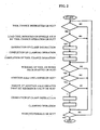
- the fundamental principle of the basic structure is generation of clamp instruction when the rotational torque generated at an addition axle becomes equal to or greater than a predetermined reference value as a consequence of working on a work piece carried out by the rotation or pressing of a tool.
- a clamp instruction during a process program is neglected, and the rotational torque is measured after working on the work piece with a tool, to determine whether or not the torque is equal to or greater than a predetermined reference value, so that, when the torque is equal to or greater than the reference value, an clamp instruction is generated.
- the addition axle is coupled by the grasp that is achieved by pressure applied by a coupling portion between the addition axle and a drive source.
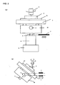
- the coupling works against the rotational torque generated at the addition axle to prevent the rotation to cause a table to rotate in a plane direction or the rotation to cause the table to revolve as shown in Figs. 3A and 3B , and maintains the grasp state.
- a clamp instruction is generated so that a brake piece acts to clamp the addition axle so as to secure the addition axle.
- the reference value is set to a numerical value which does not cause the above-mentioned slip.
- Example 1 is characterized in that when two addition axle of different directions are coupled to one table, selection of whether or not the clamp instruction for one addition axle is needed and generation of the clamp instruction when needed, and selection of clamping for the other addition axle and generation of the clamp instruction when needed are effected at approximately same timings.
- Fig. 1 omits a case where a load tool works. However, in a case where the load tool works, as shown in Fig. 4 , steps of determining beforehand whether or not the tool corresponds to a load tool, and, when corresponding to the load tool, generating a clamp instruction and instructing the load tool to work should be added separately.
- Example 2 is characterized in that in a case of handling a load tool, as shown in Fig. 2 , at the time of instructing tool change, it is determined whether or not the load tool is to be disposed on a spindle axle through a tool change operation, and when the tool is the load tool, the clamp instruction is generated during the tool change operation.
- Example 2 simultaneous clamping is executed during the tool change operation of mounting the load tool to the spindle axle, thereby shortening the machining time.
- the present invention can be adapted in all fields of machining which use a table supported by an addition axle.
Landscapes
- Engineering & Computer Science (AREA)
- Mechanical Engineering (AREA)
- Numerical Control (AREA)
- Shovels (AREA)
- Machine Tool Positioning Apparatuses (AREA)
Claims (4)
- Klemmanweisungsverfahren zum Festklemmen der Drehung eines Tisches (1), der ein Werkstück (2) oder eine Palette trägt, auf der ein Werkstück (2) angebracht ist, wobei eine Zusatzachse (4) mit dem Tisch (1) gekoppelt ist und von einem durch einen Kupplungsabschnitt (6) ausgeübten Druck festgehalten wird, dadurch gekennzeichnet, dass das Verfahren während einer Phase der Bearbeitung des Werkstücks (2) mit einem Werkzeug (3) die folgenden Schritte umfasst:- Messen eines durch die Bearbeitung des Werkstücks (2) erzeugten Rotationsdrehmoments bezüglich der Zusatzachse (4); und- Erzeugen einer Anweisung zum Festklemmen der Zusatzachse (4) durch ein Bremsteil (7), wenn das gemessene Rotationsdrehmoment einen vorher bestimmten Referenzwert überschreitet, der auf einen numerischen Wert so eingestellt ist, dass zwischen der Zusatzachse (4) und dem Kupplungsabschnitt (6) kein Schlupf auftritt, und Nicht-Erzeugen einer Anweisung zum Festklemmen der Zusatzachse (4), wenn das gemessene Rotationsdrehmoment den vorher bestimmten Wert nicht überschreitet.
- Klemmanweisungsverfahren zum Festklemmen der Drehung eines Tisches (1), der ein Werkstück (2) oder eine Palette trägt, auf der ein Werkstück (2) angebracht ist, wobei eine Zusatzachse (4) mit dem Tisch (1) gekoppelt ist und von einem durch einen Kupplungsabschnitt (6) ausgeübten Druck festgehalten wird, dadurch gekennzeichnet, dass das Verfahren während einer Phase vor der Bearbeitung des Werkstücks (2) mit einem Werkzeug (3) die folgenden Schritte umfasst:- Bestimmen, ob das Werkzeug (3) ein Lastwerkzeug ist, dessen Bearbeitung ein Drehmoment an der Zusatzachse (4) erzeugt, das im Voraus als Überschreitung eines eingestellten Referenzwerts angesehen wurde,- Erzeugen einer Anweisung zum Festklemmen der Zusatzachse (4) durch ein Bremsteil (7), wenn das Werkzeug (3) das Lastwerkzeug ist, so dass zwischen der Zusatzachse (4) und dem Kupplungsabschnitt (6) kein Schlupf auftritt, und- Nicht-Erzeugen einer Anweisung zum Festklemmen der Zusatzachse (4) durch ein Bremsteil (7), wenn das Werkzeug (3) kein Lastwerkzeug ist.
- Klemmanweisungsverfahren nach Anspruch 2, wobei zu einem Zeitpunkt des Anweisens eines Wechsels des Werkzeugs (3) bestimmt wird, ob durch einen Vorgang zum Wechseln eines Werkzeugs (3) ein Lastwerkzeug an einer Spindelachse (4) anzubringen ist oder nicht, und wenn das Werkzeug (3) das Lastwerkzeug ist, während des Vorgangs zum Wechseln des Werkzeugs (3) die Anweisung zum Festklemmen erzeugt wird.
- Klemmanweisungsverfahren nach Anspruch 1, wobei, wenn zwei Zusatzachsen mit unterschiedlichen Richtungen mit einem Tisch (1) gekoppelt sind, eine Auswahl, ob das Festklemmen einer Zusatzachse (4) erforderlich ist oder nicht, und die Erzeugung der Anweisung zum Festklemmen der einen Zusatzachse (4), falls erforderlich, und eine Auswahl des Festklemmens für die andere Zusatzachse (4) und die Erzeugung der Anweisung zum Festklemmen der anderen Achse (4), falls erforderlich, ungefähr gleichzeitig bewirkt werden.
Applications Claiming Priority (1)
| Application Number | Priority Date | Filing Date | Title |
|---|---|---|---|
| JP2007232273A JP4931744B2 (ja) | 2007-09-07 | 2007-09-07 | クランプ指令方法 |
Publications (2)
| Publication Number | Publication Date |
|---|---|
| EP2033737A1 EP2033737A1 (de) | 2009-03-11 |
| EP2033737B1 true EP2033737B1 (de) | 2010-04-21 |
Family
ID=39295993
Family Applications (1)
| Application Number | Title | Priority Date | Filing Date |
|---|---|---|---|
| EP08003578A Active EP2033737B1 (de) | 2007-09-07 | 2008-02-27 | Klemmanweisungsverfahren |
Country Status (5)
| Country | Link |
|---|---|
| US (1) | US7937181B2 (de) |
| EP (1) | EP2033737B1 (de) |
| JP (1) | JP4931744B2 (de) |
| DE (1) | DE602008001041D1 (de) |
| ES (1) | ES2342441T3 (de) |
Families Citing this family (1)
| Publication number | Priority date | Publication date | Assignee | Title |
|---|---|---|---|---|
| JP7250202B1 (ja) | 2022-08-25 | 2023-03-31 | Dmg森精機株式会社 | 情報処理装置および情報処理プログラム |
Family Cites Families (13)
| Publication number | Priority date | Publication date | Assignee | Title |
|---|---|---|---|---|
| CA1233222A (en) * | 1984-03-09 | 1988-02-23 | Nobuhiko Onda | Movable apparatus driving system |
| JPH05177490A (ja) * | 1991-12-25 | 1993-07-20 | Yokogawa Electric Corp | 加工装置 |
| DE4326275C2 (de) * | 1993-08-05 | 1997-10-09 | Erowa Ag | Verfahren zum Positionieren eines Werkstückträgers in einer Bearbeitungsmaschine sowie Werkstückträger zur Durchführung des Verfahrens |
| JPH0885044A (ja) * | 1994-09-19 | 1996-04-02 | Fanuc Ltd | 加工負荷監視方式 |
| JP3399134B2 (ja) * | 1994-12-12 | 2003-04-21 | 株式会社明電舎 | 極数切替電動機の運転制御装置 |
| US5738177A (en) | 1995-07-28 | 1998-04-14 | Black & Decker Inc. | Production assembly tool |
| US5947671A (en) | 1998-01-30 | 1999-09-07 | Power Tool Holders Incorporated | Hand actuable clamping device with circumferentially extending tightening members |
| JPH11296214A (ja) * | 1998-04-07 | 1999-10-29 | Mitsubishi Electric Corp | 数値制御装置 |
| TWI222908B (en) | 2001-08-30 | 2004-11-01 | Toshiba Machine Co Ltd | Vertical lathe, tool head for vertical lathe, rotary table apparatus for machine tool |
| US7327066B2 (en) * | 2005-03-01 | 2008-02-05 | Nidec Corporation | Motor and recording disk drive device provided with the same |
| JP2006068901A (ja) * | 2005-11-16 | 2006-03-16 | Makino Milling Mach Co Ltd | 工作機械の制御装置 |
| JP2008052362A (ja) * | 2006-08-22 | 2008-03-06 | Toshiba Corp | 自律移動装置 |
| US8260535B2 (en) * | 2007-09-28 | 2012-09-04 | Bombardier Recreational Products Inc. | Load sensor for a vehicle electronic stability system |
-
2007
- 2007-09-07 JP JP2007232273A patent/JP4931744B2/ja active Active
-
2008
- 2008-01-15 US US12/014,346 patent/US7937181B2/en active Active
- 2008-02-27 DE DE602008001041T patent/DE602008001041D1/de active Active
- 2008-02-27 EP EP08003578A patent/EP2033737B1/de active Active
- 2008-02-27 ES ES08003578T patent/ES2342441T3/es active Active
Also Published As
| Publication number | Publication date |
|---|---|
| US20090065993A1 (en) | 2009-03-12 |
| ES2342441T3 (es) | 2010-07-06 |
| JP2009064292A (ja) | 2009-03-26 |
| JP4931744B2 (ja) | 2012-05-16 |
| EP2033737A1 (de) | 2009-03-11 |
| DE602008001041D1 (de) | 2010-06-02 |
| US7937181B2 (en) | 2011-05-03 |
Similar Documents
| Publication | Publication Date | Title |
|---|---|---|
| EP3090832B1 (de) | Bearbeitungsunterstützungssystem für werkstück mit geringer festigkeit | |
| JP5015816B2 (ja) | 心押台制御装置 | |
| JP5607690B2 (ja) | 回転テーブルを備えた工作機械 | |
| KR101396689B1 (ko) | 공작 기계 | |
| EP2164663B1 (de) | Verfahren zur steuerung einer bohrmaschine und vorrichtung zur durchführung des verfahrens | |
| JPWO1999011409A1 (ja) | 自動施盤及びその制御方法 | |
| Suzuki et al. | Effect of cross transfer function on chatter stability in plunge cutting | |
| JPH09300114A (ja) | ロボットによる穴明け装置 | |
| JP6562545B2 (ja) | 旋盤 | |
| US7937181B2 (en) | Clamp instruction method | |
| JP2018161724A (ja) | 工作機械システムおよびクランプ方法 | |
| JP2002239803A (ja) | 加工装置及び加工方法 | |
| KR102010590B1 (ko) | 공작기계의 스핀들 클램핑/언클램핑 자동 조절 장치 및 방법 | |
| JPH0655408A (ja) | ワークの変形防止クランプ方法 | |
| JP4575847B2 (ja) | 心押台制御装置および心押動作の制御方法 | |
| JP2009066755A (ja) | 工作機械にて遠心力補正を行う方法および装置 | |
| JP7375626B2 (ja) | 締め付け装置及び工作機械 | |
| JP3361119B2 (ja) | 旋盤における小径ドリル加工方法 | |
| JP2004148422A (ja) | 多軸加工装置、多軸加工装置での加工方法、プログラム | |
| JPH06161527A (ja) | 数値制御装置 | |
| KR20140080268A (ko) | 선반의 스핀들 댐핑 제어장치 및 방법 | |
| JPH0288101A (ja) | 対向型2軸スピンドル旋盤のワーク授受確認方法とその制御装置 | |
| CN211102833U (zh) | 一种卧式钻床工装夹具 | |
| CN211680025U (zh) | 一种正背面加工夹具 | |
| JP4257511B2 (ja) | Nc加工装置 |
Legal Events
| Date | Code | Title | Description |
|---|---|---|---|
| PUAI | Public reference made under article 153(3) epc to a published international application that has entered the european phase |
Free format text: ORIGINAL CODE: 0009012 |
|
| 17P | Request for examination filed |
Effective date: 20080804 |
|
| AK | Designated contracting states |
Kind code of ref document: A1 Designated state(s): AT BE BG CH CY CZ DE DK EE ES FI FR GB GR HR HU IE IS IT LI LT LU LV MC MT NL NO PL PT RO SE SI SK TR |
|
| AX | Request for extension of the european patent |
Extension state: AL BA MK RS |
|
| GRAP | Despatch of communication of intention to grant a patent |
Free format text: ORIGINAL CODE: EPIDOSNIGR1 |
|
| AKX | Designation fees paid |
Designated state(s): CH DE ES GB IT LI |
|
| GRAS | Grant fee paid |
Free format text: ORIGINAL CODE: EPIDOSNIGR3 |
|
| GRAA | (expected) grant |
Free format text: ORIGINAL CODE: 0009210 |
|
| AK | Designated contracting states |
Kind code of ref document: B1 Designated state(s): CH DE ES GB IT LI |
|
| REG | Reference to a national code |
Ref country code: GB Ref legal event code: FG4D |
|
| REG | Reference to a national code |
Ref country code: CH Ref legal event code: NV Representative=s name: ING. MARCO ZARDI C/O M. ZARDI & CO. S.A. Ref country code: CH Ref legal event code: EP |
|
| REF | Corresponds to: |
Ref document number: 602008001041 Country of ref document: DE Date of ref document: 20100602 Kind code of ref document: P |
|
| REG | Reference to a national code |
Ref country code: ES Ref legal event code: FG2A Ref document number: 2342441 Country of ref document: ES Kind code of ref document: T3 |
|
| PLBE | No opposition filed within time limit |
Free format text: ORIGINAL CODE: 0009261 |
|
| STAA | Information on the status of an ep patent application or granted ep patent |
Free format text: STATUS: NO OPPOSITION FILED WITHIN TIME LIMIT |
|
| 26N | No opposition filed |
Effective date: 20110124 |
|
| REG | Reference to a national code |
Ref country code: CH Ref legal event code: U11 Free format text: ST27 STATUS EVENT CODE: U-0-0-U10-U11 (AS PROVIDED BY THE NATIONAL OFFICE) Effective date: 20260301 |
|
| PGFP | Annual fee paid to national office [announced via postgrant information from national office to epo] |
Ref country code: GB Payment date: 20260226 Year of fee payment: 19 |
|
| PGFP | Annual fee paid to national office [announced via postgrant information from national office to epo] |
Ref country code: ES Payment date: 20260302 Year of fee payment: 19 |
|
| PGFP | Annual fee paid to national office [announced via postgrant information from national office to epo] |
Ref country code: DE Payment date: 20260129 Year of fee payment: 19 |
|
| PGFP | Annual fee paid to national office [announced via postgrant information from national office to epo] |
Ref country code: IT Payment date: 20260227 Year of fee payment: 19 |
|
| PGFP | Annual fee paid to national office [announced via postgrant information from national office to epo] |
Ref country code: CH Payment date: 20260301 Year of fee payment: 19 |