EP2032746B1 - Method for continual preparation of polycrystalline silicon using a fluidized bed reactor - Google Patents
Method for continual preparation of polycrystalline silicon using a fluidized bed reactor Download PDFInfo
- Publication number
- EP2032746B1 EP2032746B1 EP07746914.6A EP07746914A EP2032746B1 EP 2032746 B1 EP2032746 B1 EP 2032746B1 EP 07746914 A EP07746914 A EP 07746914A EP 2032746 B1 EP2032746 B1 EP 2032746B1
- Authority
- EP
- European Patent Office
- Prior art keywords
- silicon
- gas
- reactor
- zone
- fluidized bed
- Prior art date
- Legal status (The legal status is an assumption and is not a legal conclusion. Google has not performed a legal analysis and makes no representation as to the accuracy of the status listed.)
- Not-in-force
Links
- 238000002360 preparation method Methods 0.000 title claims description 114
- 229910021420 polycrystalline silicon Inorganic materials 0.000 title claims description 93
- 238000000034 method Methods 0.000 title claims description 70
- 239000011856 silicon-based particle Substances 0.000 claims description 281
- XUIMIQQOPSSXEZ-UHFFFAOYSA-N Silicon Chemical compound [Si] XUIMIQQOPSSXEZ-UHFFFAOYSA-N 0.000 claims description 247
- 229910052710 silicon Inorganic materials 0.000 claims description 241
- 239000010703 silicon Substances 0.000 claims description 241
- 239000007789 gas Substances 0.000 claims description 216
- 239000012495 reaction gas Substances 0.000 claims description 137
- 238000006243 chemical reaction Methods 0.000 claims description 102
- 238000010438 heat treatment Methods 0.000 claims description 86
- 238000005530 etching Methods 0.000 claims description 81
- 230000008021 deposition Effects 0.000 claims description 79
- 239000002245 particle Substances 0.000 claims description 70
- 238000007599 discharging Methods 0.000 claims description 68
- 239000011261 inert gas Substances 0.000 claims description 43
- 239000000463 material Substances 0.000 claims description 31
- XKRFYHLGVUSROY-UHFFFAOYSA-N Argon Chemical compound [Ar] XKRFYHLGVUSROY-UHFFFAOYSA-N 0.000 claims description 30
- IJGRMHOSHXDMSA-UHFFFAOYSA-N Atomic nitrogen Chemical compound N#N IJGRMHOSHXDMSA-UHFFFAOYSA-N 0.000 claims description 29
- VXEGSRKPIUDPQT-UHFFFAOYSA-N 4-[4-(4-methoxyphenyl)piperazin-1-yl]aniline Chemical compound C1=CC(OC)=CC=C1N1CCN(C=2C=CC(N)=CC=2)CC1 VXEGSRKPIUDPQT-UHFFFAOYSA-N 0.000 claims description 21
- 239000005049 silicon tetrachloride Substances 0.000 claims description 21
- 239000000126 substance Substances 0.000 claims description 21
- 230000036961 partial effect Effects 0.000 claims description 18
- 229910052739 hydrogen Inorganic materials 0.000 claims description 17
- 239000001257 hydrogen Substances 0.000 claims description 17
- 238000012856 packing Methods 0.000 claims description 17
- 229910052786 argon Inorganic materials 0.000 claims description 15
- 239000001307 helium Substances 0.000 claims description 15
- 229910052734 helium Inorganic materials 0.000 claims description 15
- SWQJXJOGLNCZEY-UHFFFAOYSA-N helium atom Chemical compound [He] SWQJXJOGLNCZEY-UHFFFAOYSA-N 0.000 claims description 15
- VEXZGXHMUGYJMC-UHFFFAOYSA-N Hydrochloric acid Chemical compound Cl VEXZGXHMUGYJMC-UHFFFAOYSA-N 0.000 claims description 14
- 229910052757 nitrogen Inorganic materials 0.000 claims description 14
- ZAMOUSCENKQFHK-UHFFFAOYSA-N Chlorine atom Chemical compound [Cl] ZAMOUSCENKQFHK-UHFFFAOYSA-N 0.000 claims description 12
- 239000000460 chlorine Substances 0.000 claims description 12
- 229910052801 chlorine Inorganic materials 0.000 claims description 12
- BLRPTPMANUNPDV-UHFFFAOYSA-N Silane Chemical compound [SiH4] BLRPTPMANUNPDV-UHFFFAOYSA-N 0.000 claims description 11
- ZDHXKXAHOVTTAH-UHFFFAOYSA-N trichlorosilane Chemical compound Cl[SiH](Cl)Cl ZDHXKXAHOVTTAH-UHFFFAOYSA-N 0.000 claims description 11
- 239000005052 trichlorosilane Substances 0.000 claims description 11
- 239000006227 byproduct Substances 0.000 claims description 8
- 229910000041 hydrogen chloride Inorganic materials 0.000 claims description 8
- IXCSERBJSXMMFS-UHFFFAOYSA-N hydrogen chloride Substances Cl.Cl IXCSERBJSXMMFS-UHFFFAOYSA-N 0.000 claims description 8
- BUMGIEFFCMBQDG-UHFFFAOYSA-N dichlorosilicon Chemical compound Cl[Si]Cl BUMGIEFFCMBQDG-UHFFFAOYSA-N 0.000 claims description 6
- 150000003377 silicon compounds Chemical class 0.000 claims description 5
- KZBUYRJDOAKODT-UHFFFAOYSA-N Chlorine Chemical compound ClCl KZBUYRJDOAKODT-UHFFFAOYSA-N 0.000 claims description 3
- 239000007795 chemical reaction product Substances 0.000 claims description 3
- MROCJMGDEKINLD-UHFFFAOYSA-N dichlorosilane Chemical compound Cl[SiH2]Cl MROCJMGDEKINLD-UHFFFAOYSA-N 0.000 claims description 2
- 125000004435 hydrogen atom Chemical class [H]* 0.000 claims 2
- 238000000151 deposition Methods 0.000 description 76
- 239000000047 product Substances 0.000 description 31
- 239000013078 crystal Substances 0.000 description 25
- 238000004519 manufacturing process Methods 0.000 description 14
- 239000000203 mixture Substances 0.000 description 12
- 239000012535 impurity Substances 0.000 description 11
- 238000011109 contamination Methods 0.000 description 10
- 150000002431 hydrogen Chemical class 0.000 description 10
- 238000005137 deposition process Methods 0.000 description 8
- 229910010272 inorganic material Inorganic materials 0.000 description 8
- 239000011147 inorganic material Substances 0.000 description 8
- 230000008569 process Effects 0.000 description 8
- 238000005243 fluidization Methods 0.000 description 7
- 239000007769 metal material Substances 0.000 description 7
- VYPSYNLAJGMNEJ-UHFFFAOYSA-N silicon dioxide Inorganic materials O=[Si]=O VYPSYNLAJGMNEJ-UHFFFAOYSA-N 0.000 description 7
- OKTJSMMVPCPJKN-UHFFFAOYSA-N Carbon Chemical compound [C] OKTJSMMVPCPJKN-UHFFFAOYSA-N 0.000 description 6
- 238000005259 measurement Methods 0.000 description 6
- 238000010298 pulverizing process Methods 0.000 description 6
- UFHFLCQGNIYNRP-UHFFFAOYSA-N Hydrogen Chemical compound [H][H] UFHFLCQGNIYNRP-UHFFFAOYSA-N 0.000 description 5
- 238000009825 accumulation Methods 0.000 description 5
- 239000002826 coolant Substances 0.000 description 5
- 239000007787 solid Substances 0.000 description 5
- 238000012546 transfer Methods 0.000 description 5
- 230000008901 benefit Effects 0.000 description 4
- 238000010276 construction Methods 0.000 description 4
- 238000009826 distribution Methods 0.000 description 4
- 230000033001 locomotion Effects 0.000 description 4
- 238000007789 sealing Methods 0.000 description 4
- 238000000926 separation method Methods 0.000 description 4
- 238000003860 storage Methods 0.000 description 4
- 230000015572 biosynthetic process Effects 0.000 description 3
- 229910052799 carbon Inorganic materials 0.000 description 3
- 239000000919 ceramic Substances 0.000 description 3
- 150000001805 chlorine compounds Chemical class 0.000 description 3
- 238000010924 continuous production Methods 0.000 description 3
- 229910002804 graphite Inorganic materials 0.000 description 3
- 239000010439 graphite Substances 0.000 description 3
- 239000012774 insulation material Substances 0.000 description 3
- 230000001788 irregular Effects 0.000 description 3
- 239000010410 layer Substances 0.000 description 3
- 239000003921 oil Substances 0.000 description 3
- 239000010453 quartz Substances 0.000 description 3
- 230000009467 reduction Effects 0.000 description 3
- 230000002829 reductive effect Effects 0.000 description 3
- HBMJWWWQQXIZIP-UHFFFAOYSA-N silicon carbide Chemical compound [Si+]#[C-] HBMJWWWQQXIZIP-UHFFFAOYSA-N 0.000 description 3
- 229910010271 silicon carbide Inorganic materials 0.000 description 3
- 239000011863 silicon-based powder Substances 0.000 description 3
- 238000005979 thermal decomposition reaction Methods 0.000 description 3
- XLYOFNOQVPJJNP-UHFFFAOYSA-N water Substances O XLYOFNOQVPJJNP-UHFFFAOYSA-N 0.000 description 3
- 239000005046 Chlorosilane Substances 0.000 description 2
- 229910052581 Si3N4 Inorganic materials 0.000 description 2
- 238000004458 analytical method Methods 0.000 description 2
- 230000008859 change Effects 0.000 description 2
- KOPOQZFJUQMUML-UHFFFAOYSA-N chlorosilane Chemical compound Cl[SiH3] KOPOQZFJUQMUML-UHFFFAOYSA-N 0.000 description 2
- 239000002131 composite material Substances 0.000 description 2
- 238000001816 cooling Methods 0.000 description 2
- 230000007423 decrease Effects 0.000 description 2
- 239000003085 diluting agent Substances 0.000 description 2
- 238000005265 energy consumption Methods 0.000 description 2
- 239000000945 filler Substances 0.000 description 2
- 229910021397 glassy carbon Inorganic materials 0.000 description 2
- 239000008187 granular material Substances 0.000 description 2
- 238000011065 in-situ storage Methods 0.000 description 2
- 238000011031 large-scale manufacturing process Methods 0.000 description 2
- 239000002184 metal Substances 0.000 description 2
- 229910052751 metal Inorganic materials 0.000 description 2
- 229920000620 organic polymer Polymers 0.000 description 2
- 229920005591 polysilicon Polymers 0.000 description 2
- 238000010926 purge Methods 0.000 description 2
- 230000005855 radiation Effects 0.000 description 2
- 229910000077 silane Inorganic materials 0.000 description 2
- -1 silane compound Chemical class 0.000 description 2
- 239000000377 silicon dioxide Substances 0.000 description 2
- HQVNEWCFYHHQES-UHFFFAOYSA-N silicon nitride Chemical compound N12[Si]34N5[Si]62N3[Si]51N64 HQVNEWCFYHHQES-UHFFFAOYSA-N 0.000 description 2
- 230000002459 sustained effect Effects 0.000 description 2
- 230000036962 time dependent Effects 0.000 description 2
- 229910052582 BN Inorganic materials 0.000 description 1
- PZNSFCLAULLKQX-UHFFFAOYSA-N Boron nitride Chemical compound N#B PZNSFCLAULLKQX-UHFFFAOYSA-N 0.000 description 1
- 229910000975 Carbon steel Inorganic materials 0.000 description 1
- YCKRFDGAMUMZLT-UHFFFAOYSA-N Fluorine atom Chemical compound [F] YCKRFDGAMUMZLT-UHFFFAOYSA-N 0.000 description 1
- 206010017577 Gait disturbance Diseases 0.000 description 1
- 229910000831 Steel Inorganic materials 0.000 description 1
- 239000000654 additive Substances 0.000 description 1
- 230000000996 additive effect Effects 0.000 description 1
- 238000005054 agglomeration Methods 0.000 description 1
- 230000002776 aggregation Effects 0.000 description 1
- 239000003570 air Substances 0.000 description 1
- 229910045601 alloy Inorganic materials 0.000 description 1
- 239000000956 alloy Substances 0.000 description 1
- QVGXLLKOCUKJST-UHFFFAOYSA-N atomic oxygen Chemical compound [O] QVGXLLKOCUKJST-UHFFFAOYSA-N 0.000 description 1
- 238000009530 blood pressure measurement Methods 0.000 description 1
- 238000012769 bulk production Methods 0.000 description 1
- 239000010962 carbon steel Substances 0.000 description 1
- 238000001311 chemical methods and process Methods 0.000 description 1
- 150000001875 compounds Chemical class 0.000 description 1
- 239000004020 conductor Substances 0.000 description 1
- 239000012809 cooling fluid Substances 0.000 description 1
- 238000005336 cracking Methods 0.000 description 1
- 238000013016 damping Methods 0.000 description 1
- 230000003247 decreasing effect Effects 0.000 description 1
- 238000001514 detection method Methods 0.000 description 1
- 230000002542 deteriorative effect Effects 0.000 description 1
- 238000010292 electrical insulation Methods 0.000 description 1
- 238000002474 experimental method Methods 0.000 description 1
- 239000004744 fabric Substances 0.000 description 1
- 229910052731 fluorine Inorganic materials 0.000 description 1
- 239000011737 fluorine Substances 0.000 description 1
- 239000012634 fragment Substances 0.000 description 1
- 230000006872 improvement Effects 0.000 description 1
- 230000002452 interceptive effect Effects 0.000 description 1
- 230000000670 limiting effect Effects 0.000 description 1
- 230000007774 longterm Effects 0.000 description 1
- 238000012423 maintenance Methods 0.000 description 1
- 150000002739 metals Chemical class 0.000 description 1
- 238000012986 modification Methods 0.000 description 1
- 230000004048 modification Effects 0.000 description 1
- 238000012544 monitoring process Methods 0.000 description 1
- 238000013021 overheating Methods 0.000 description 1
- 239000001301 oxygen Substances 0.000 description 1
- 229910052760 oxygen Inorganic materials 0.000 description 1
- 238000005192 partition Methods 0.000 description 1
- 239000008188 pellet Substances 0.000 description 1
- 239000002861 polymer material Substances 0.000 description 1
- 230000002265 prevention Effects 0.000 description 1
- 238000012545 processing Methods 0.000 description 1
- 230000001681 protective effect Effects 0.000 description 1
- 239000011241 protective layer Substances 0.000 description 1
- 238000000197 pyrolysis Methods 0.000 description 1
- 239000003566 sealing material Substances 0.000 description 1
- 239000004065 semiconductor Substances 0.000 description 1
- 150000003376 silicon Chemical class 0.000 description 1
- 239000002210 silicon-based material Substances 0.000 description 1
- 238000000638 solvent extraction Methods 0.000 description 1
- 230000002269 spontaneous effect Effects 0.000 description 1
- 239000010935 stainless steel Substances 0.000 description 1
- 229910001220 stainless steel Inorganic materials 0.000 description 1
- 239000010959 steel Substances 0.000 description 1
- 238000004381 surface treatment Methods 0.000 description 1
- 230000001960 triggered effect Effects 0.000 description 1
Images


Classifications
-
- C—CHEMISTRY; METALLURGY
- C30—CRYSTAL GROWTH
- C30B—SINGLE-CRYSTAL GROWTH; UNIDIRECTIONAL SOLIDIFICATION OF EUTECTIC MATERIAL OR UNIDIRECTIONAL DEMIXING OF EUTECTOID MATERIAL; REFINING BY ZONE-MELTING OF MATERIAL; PRODUCTION OF A HOMOGENEOUS POLYCRYSTALLINE MATERIAL WITH DEFINED STRUCTURE; SINGLE CRYSTALS OR HOMOGENEOUS POLYCRYSTALLINE MATERIAL WITH DEFINED STRUCTURE; AFTER-TREATMENT OF SINGLE CRYSTALS OR A HOMOGENEOUS POLYCRYSTALLINE MATERIAL WITH DEFINED STRUCTURE; APPARATUS THEREFOR
- C30B29/00—Single crystals or homogeneous polycrystalline material with defined structure characterised by the material or by their shape
- C30B29/02—Elements
- C30B29/06—Silicon
-
- B—PERFORMING OPERATIONS; TRANSPORTING
- B01—PHYSICAL OR CHEMICAL PROCESSES OR APPARATUS IN GENERAL
- B01J—CHEMICAL OR PHYSICAL PROCESSES, e.g. CATALYSIS OR COLLOID CHEMISTRY; THEIR RELEVANT APPARATUS
- B01J19/00—Chemical, physical or physico-chemical processes in general; Their relevant apparatus
- B01J19/02—Apparatus characterised by being constructed of material selected for its chemically-resistant properties
-
- B—PERFORMING OPERATIONS; TRANSPORTING
- B01—PHYSICAL OR CHEMICAL PROCESSES OR APPARATUS IN GENERAL
- B01J—CHEMICAL OR PHYSICAL PROCESSES, e.g. CATALYSIS OR COLLOID CHEMISTRY; THEIR RELEVANT APPARATUS
- B01J8/00—Chemical or physical processes in general, conducted in the presence of fluids and solid particles; Apparatus for such processes
- B01J8/18—Chemical or physical processes in general, conducted in the presence of fluids and solid particles; Apparatus for such processes with fluidised particles
- B01J8/1809—Controlling processes
-
- B—PERFORMING OPERATIONS; TRANSPORTING
- B01—PHYSICAL OR CHEMICAL PROCESSES OR APPARATUS IN GENERAL
- B01J—CHEMICAL OR PHYSICAL PROCESSES, e.g. CATALYSIS OR COLLOID CHEMISTRY; THEIR RELEVANT APPARATUS
- B01J8/00—Chemical or physical processes in general, conducted in the presence of fluids and solid particles; Apparatus for such processes
- B01J8/18—Chemical or physical processes in general, conducted in the presence of fluids and solid particles; Apparatus for such processes with fluidised particles
- B01J8/1818—Feeding of the fluidising gas
- B01J8/1827—Feeding of the fluidising gas the fluidising gas being a reactant
-
- B—PERFORMING OPERATIONS; TRANSPORTING
- B01—PHYSICAL OR CHEMICAL PROCESSES OR APPARATUS IN GENERAL
- B01J—CHEMICAL OR PHYSICAL PROCESSES, e.g. CATALYSIS OR COLLOID CHEMISTRY; THEIR RELEVANT APPARATUS
- B01J8/00—Chemical or physical processes in general, conducted in the presence of fluids and solid particles; Apparatus for such processes
- B01J8/18—Chemical or physical processes in general, conducted in the presence of fluids and solid particles; Apparatus for such processes with fluidised particles
- B01J8/1836—Heating and cooling the reactor
-
- B—PERFORMING OPERATIONS; TRANSPORTING
- B01—PHYSICAL OR CHEMICAL PROCESSES OR APPARATUS IN GENERAL
- B01J—CHEMICAL OR PHYSICAL PROCESSES, e.g. CATALYSIS OR COLLOID CHEMISTRY; THEIR RELEVANT APPARATUS
- B01J8/00—Chemical or physical processes in general, conducted in the presence of fluids and solid particles; Apparatus for such processes
- B01J8/18—Chemical or physical processes in general, conducted in the presence of fluids and solid particles; Apparatus for such processes with fluidised particles
- B01J8/24—Chemical or physical processes in general, conducted in the presence of fluids and solid particles; Apparatus for such processes with fluidised particles according to "fluidised-bed" technique
- B01J8/34—Chemical or physical processes in general, conducted in the presence of fluids and solid particles; Apparatus for such processes with fluidised particles according to "fluidised-bed" technique with stationary packing material in the fluidised bed, e.g. bricks, wire rings, baffles
-
- C—CHEMISTRY; METALLURGY
- C01—INORGANIC CHEMISTRY
- C01B—NON-METALLIC ELEMENTS; COMPOUNDS THEREOF; METALLOIDS OR COMPOUNDS THEREOF NOT COVERED BY SUBCLASS C01C
- C01B33/00—Silicon; Compounds thereof
- C01B33/02—Silicon
- C01B33/021—Preparation
- C01B33/027—Preparation by decomposition or reduction of gaseous or vaporised silicon compounds other than silica or silica-containing material
-
- C—CHEMISTRY; METALLURGY
- C30—CRYSTAL GROWTH
- C30B—SINGLE-CRYSTAL GROWTH; UNIDIRECTIONAL SOLIDIFICATION OF EUTECTIC MATERIAL OR UNIDIRECTIONAL DEMIXING OF EUTECTOID MATERIAL; REFINING BY ZONE-MELTING OF MATERIAL; PRODUCTION OF A HOMOGENEOUS POLYCRYSTALLINE MATERIAL WITH DEFINED STRUCTURE; SINGLE CRYSTALS OR HOMOGENEOUS POLYCRYSTALLINE MATERIAL WITH DEFINED STRUCTURE; AFTER-TREATMENT OF SINGLE CRYSTALS OR A HOMOGENEOUS POLYCRYSTALLINE MATERIAL WITH DEFINED STRUCTURE; APPARATUS THEREFOR
- C30B28/00—Production of homogeneous polycrystalline material with defined structure
- C30B28/12—Production of homogeneous polycrystalline material with defined structure directly from the gas state
- C30B28/14—Production of homogeneous polycrystalline material with defined structure directly from the gas state by chemical reaction of reactive gases
-
- C—CHEMISTRY; METALLURGY
- C30—CRYSTAL GROWTH
- C30B—SINGLE-CRYSTAL GROWTH; UNIDIRECTIONAL SOLIDIFICATION OF EUTECTIC MATERIAL OR UNIDIRECTIONAL DEMIXING OF EUTECTOID MATERIAL; REFINING BY ZONE-MELTING OF MATERIAL; PRODUCTION OF A HOMOGENEOUS POLYCRYSTALLINE MATERIAL WITH DEFINED STRUCTURE; SINGLE CRYSTALS OR HOMOGENEOUS POLYCRYSTALLINE MATERIAL WITH DEFINED STRUCTURE; AFTER-TREATMENT OF SINGLE CRYSTALS OR A HOMOGENEOUS POLYCRYSTALLINE MATERIAL WITH DEFINED STRUCTURE; APPARATUS THEREFOR
- C30B35/00—Apparatus not otherwise provided for, specially adapted for the growth, production or after-treatment of single crystals or of a homogeneous polycrystalline material with defined structure
-
- B—PERFORMING OPERATIONS; TRANSPORTING
- B01—PHYSICAL OR CHEMICAL PROCESSES OR APPARATUS IN GENERAL
- B01J—CHEMICAL OR PHYSICAL PROCESSES, e.g. CATALYSIS OR COLLOID CHEMISTRY; THEIR RELEVANT APPARATUS
- B01J2208/00—Processes carried out in the presence of solid particles; Reactors therefor
- B01J2208/00008—Controlling the process
- B01J2208/00017—Controlling the temperature
- B01J2208/00389—Controlling the temperature using electric heating or cooling elements
- B01J2208/00398—Controlling the temperature using electric heating or cooling elements inside the reactor bed
-
- B—PERFORMING OPERATIONS; TRANSPORTING
- B01—PHYSICAL OR CHEMICAL PROCESSES OR APPARATUS IN GENERAL
- B01J—CHEMICAL OR PHYSICAL PROCESSES, e.g. CATALYSIS OR COLLOID CHEMISTRY; THEIR RELEVANT APPARATUS
- B01J2208/00—Processes carried out in the presence of solid particles; Reactors therefor
- B01J2208/00008—Controlling the process
- B01J2208/00017—Controlling the temperature
- B01J2208/00389—Controlling the temperature using electric heating or cooling elements
- B01J2208/00407—Controlling the temperature using electric heating or cooling elements outside the reactor bed
-
- B—PERFORMING OPERATIONS; TRANSPORTING
- B01—PHYSICAL OR CHEMICAL PROCESSES OR APPARATUS IN GENERAL
- B01J—CHEMICAL OR PHYSICAL PROCESSES, e.g. CATALYSIS OR COLLOID CHEMISTRY; THEIR RELEVANT APPARATUS
- B01J2208/00—Processes carried out in the presence of solid particles; Reactors therefor
- B01J2208/00008—Controlling the process
- B01J2208/00017—Controlling the temperature
- B01J2208/00389—Controlling the temperature using electric heating or cooling elements
- B01J2208/00415—Controlling the temperature using electric heating or cooling elements electric resistance heaters
-
- B—PERFORMING OPERATIONS; TRANSPORTING
- B01—PHYSICAL OR CHEMICAL PROCESSES OR APPARATUS IN GENERAL
- B01J—CHEMICAL OR PHYSICAL PROCESSES, e.g. CATALYSIS OR COLLOID CHEMISTRY; THEIR RELEVANT APPARATUS
- B01J2208/00—Processes carried out in the presence of solid particles; Reactors therefor
- B01J2208/00008—Controlling the process
- B01J2208/00017—Controlling the temperature
- B01J2208/00477—Controlling the temperature by thermal insulation means
- B01J2208/00495—Controlling the temperature by thermal insulation means using insulating materials or refractories
-
- B—PERFORMING OPERATIONS; TRANSPORTING
- B01—PHYSICAL OR CHEMICAL PROCESSES OR APPARATUS IN GENERAL
- B01J—CHEMICAL OR PHYSICAL PROCESSES, e.g. CATALYSIS OR COLLOID CHEMISTRY; THEIR RELEVANT APPARATUS
- B01J2208/00—Processes carried out in the presence of solid particles; Reactors therefor
- B01J2208/00008—Controlling the process
- B01J2208/00539—Pressure
-
- B—PERFORMING OPERATIONS; TRANSPORTING
- B01—PHYSICAL OR CHEMICAL PROCESSES OR APPARATUS IN GENERAL
- B01J—CHEMICAL OR PHYSICAL PROCESSES, e.g. CATALYSIS OR COLLOID CHEMISTRY; THEIR RELEVANT APPARATUS
- B01J2208/00—Processes carried out in the presence of solid particles; Reactors therefor
- B01J2208/00796—Details of the reactor or of the particulate material
- B01J2208/00823—Mixing elements
- B01J2208/00831—Stationary elements
- B01J2208/0084—Stationary elements inside the bed, e.g. baffles
-
- B—PERFORMING OPERATIONS; TRANSPORTING
- B01—PHYSICAL OR CHEMICAL PROCESSES OR APPARATUS IN GENERAL
- B01J—CHEMICAL OR PHYSICAL PROCESSES, e.g. CATALYSIS OR COLLOID CHEMISTRY; THEIR RELEVANT APPARATUS
- B01J2208/00—Processes carried out in the presence of solid particles; Reactors therefor
- B01J2208/00796—Details of the reactor or of the particulate material
- B01J2208/00991—Disengagement zone in fluidised-bed reactors
-
- B—PERFORMING OPERATIONS; TRANSPORTING
- B01—PHYSICAL OR CHEMICAL PROCESSES OR APPARATUS IN GENERAL
- B01J—CHEMICAL OR PHYSICAL PROCESSES, e.g. CATALYSIS OR COLLOID CHEMISTRY; THEIR RELEVANT APPARATUS
- B01J2219/00—Chemical, physical or physico-chemical processes in general; Their relevant apparatus
- B01J2219/02—Apparatus characterised by their chemically-resistant properties
- B01J2219/0204—Apparatus characterised by their chemically-resistant properties comprising coatings on the surfaces in direct contact with the reactive components
- B01J2219/0209—Apparatus characterised by their chemically-resistant properties comprising coatings on the surfaces in direct contact with the reactive components of glass
-
- B—PERFORMING OPERATIONS; TRANSPORTING
- B01—PHYSICAL OR CHEMICAL PROCESSES OR APPARATUS IN GENERAL
- B01J—CHEMICAL OR PHYSICAL PROCESSES, e.g. CATALYSIS OR COLLOID CHEMISTRY; THEIR RELEVANT APPARATUS
- B01J2219/00—Chemical, physical or physico-chemical processes in general; Their relevant apparatus
- B01J2219/02—Apparatus characterised by their chemically-resistant properties
- B01J2219/0204—Apparatus characterised by their chemically-resistant properties comprising coatings on the surfaces in direct contact with the reactive components
- B01J2219/0218—Apparatus characterised by their chemically-resistant properties comprising coatings on the surfaces in direct contact with the reactive components of ceramic
-
- B—PERFORMING OPERATIONS; TRANSPORTING
- B01—PHYSICAL OR CHEMICAL PROCESSES OR APPARATUS IN GENERAL
- B01J—CHEMICAL OR PHYSICAL PROCESSES, e.g. CATALYSIS OR COLLOID CHEMISTRY; THEIR RELEVANT APPARATUS
- B01J2219/00—Chemical, physical or physico-chemical processes in general; Their relevant apparatus
- B01J2219/02—Apparatus characterised by their chemically-resistant properties
- B01J2219/0204—Apparatus characterised by their chemically-resistant properties comprising coatings on the surfaces in direct contact with the reactive components
- B01J2219/0236—Metal based
-
- B—PERFORMING OPERATIONS; TRANSPORTING
- B01—PHYSICAL OR CHEMICAL PROCESSES OR APPARATUS IN GENERAL
- B01J—CHEMICAL OR PHYSICAL PROCESSES, e.g. CATALYSIS OR COLLOID CHEMISTRY; THEIR RELEVANT APPARATUS
- B01J2219/00—Chemical, physical or physico-chemical processes in general; Their relevant apparatus
- B01J2219/02—Apparatus characterised by their chemically-resistant properties
- B01J2219/025—Apparatus characterised by their chemically-resistant properties characterised by the construction materials of the reactor vessel proper
- B01J2219/0254—Glass
-
- B—PERFORMING OPERATIONS; TRANSPORTING
- B01—PHYSICAL OR CHEMICAL PROCESSES OR APPARATUS IN GENERAL
- B01J—CHEMICAL OR PHYSICAL PROCESSES, e.g. CATALYSIS OR COLLOID CHEMISTRY; THEIR RELEVANT APPARATUS
- B01J2219/00—Chemical, physical or physico-chemical processes in general; Their relevant apparatus
- B01J2219/02—Apparatus characterised by their chemically-resistant properties
- B01J2219/025—Apparatus characterised by their chemically-resistant properties characterised by the construction materials of the reactor vessel proper
- B01J2219/0272—Graphite
-
- B—PERFORMING OPERATIONS; TRANSPORTING
- B01—PHYSICAL OR CHEMICAL PROCESSES OR APPARATUS IN GENERAL
- B01J—CHEMICAL OR PHYSICAL PROCESSES, e.g. CATALYSIS OR COLLOID CHEMISTRY; THEIR RELEVANT APPARATUS
- B01J2219/00—Chemical, physical or physico-chemical processes in general; Their relevant apparatus
- B01J2219/02—Apparatus characterised by their chemically-resistant properties
- B01J2219/025—Apparatus characterised by their chemically-resistant properties characterised by the construction materials of the reactor vessel proper
- B01J2219/0277—Metal based
- B01J2219/029—Non-ferrous metals
Definitions
- the present invention relates to a method for preparation of polycrystalline silicon using a fluidized bed reactor, particularly to a method for continual preparation of polycrystalline silicon enabling effective removal of silicon deposit accumulated on the inner wall of the reactor tube of a polycrystalline silicon (multicrystalline silicon, polysilicon or poly-Si) manufacturing apparatus.
- High purity polycrystalline silicon is widely used as a chemical or an industrial source material in semiconductor devices, solar cells, etc. Also, it is used in manufacturing precision functional devices and small-sized, highly-integrated precision systems.
- the polycrystalline silicon is prepared by thermal decomposition and/or hydrogen reduction of highly-purified silicon-containing reaction gas, thus causing a continuous silicon deposition on silicon particles.
- a bell-jar type reactor In commercial-scale production of polycrystalline silicon, a bell-jar type reactor has been mainly used. Polycrystalline silicon products produced using the bell-jar type reactor is rod-shaped and has a diameter of about 50-300 mm.
- the bell-jar type reactor which consists fundamentally of the electric resistance heating system, cannot be operated continuously due to inevitable limit in extending the maximum rod diameter achievable.
- This reactor is also known to have serious problems of low deposition efficiency and high electrical energy consumption because of limited silicon surfaces and high heat loss.
- a silicon deposition process using a fluidized bed reactor to produce polycrystalline silicon in the form of particles having a size of about 0.5-3 mm According to this method, a fluidized bed of silicon particles is formed by the upward flow of gas and the size of the silicon particles increases as the silicon atoms deposit on the particles from the silicon-containing reaction gas supplied to the heated fluidized bed.
- a Si-H-Cl-based silane compound e.g., monosilane (SiH 4 ), dichlorosilane (SiH 2 Cl 2 ), trichlorosilane (SiHCl 3 ), silicon tetrachloride (SiCl 4 ) or a mixture thereof is used in the fluidized bed reactor as the silicon-containing reaction gas, which can further comprise at least one gas component selected from hydrogen, nitrogen, argon, helium, etc.
- the reaction temperature or the temperature of silicon particles, should be maintained at about 600-850 °C for monosilane, while being about 900-1,100 °C for trichlorosilane which is most widely used.
- the process of silicon deposition which is caused by thermal decomposition and/or hydrogen reduction of silicon-containing reaction gas, includes various elementary reactions, and there are complex routes where silicon atoms grow into granular particles depending on the reaction gas.
- the operation of the fluidized bed reactor yields polycrystalline silicon product in the form of particles, that is, granules.
- seed crystals become bigger in size due to continuous silicon deposition or the agglomeration of silicon particles, thereby losing fluidity and ultimately being moved downwards.
- the seed crystals may be prepared or generated in situ in the fluidized bed itself, or supplied into the reactor continuously, periodically or intermittently.
- prepared bigger particles, i.e., polycrystalline silicon product may be discharged from the lower part of the reactor continuously, periodically or intermittently.
- the fluidized bed reactor system provides a higher reaction yield than that by the bell-jar type reactor system.
- the granular product may be directly used without further processing for the follow-up processes such as single crystal growth, crystal block production, surface treatment and modification, preparation of chemical material for reaction or separation, or shaped body or pulverization of silicon particles.
- follow-up processes have been operated in a batchwise manner, the manufacture of the granular polycrystalline silicon allows the processes to be performed in a semi-continuous or continuous manner.
- the biggest stumbling block in continuous production of particle-shaped, i.e., granular polycrystalline silicon using a fluidized bed reactor is that silicon deposition by the reaction gas occurs not only on the surfaces of the silicon particles heated to a high temperature but also on the surfaces of the reactor components that are inevitably exposed to or in contact with the hot silicon particles.
- Silicon deposition occurs and is accumulated on the hot solid surfaces inside the fluidized bed reactor, including the silicon particles, the inner wall of the reactor tube and the reaction gas supplying means, all of which are exposed to the reaction gas.
- the thickness of the accumulated deposition layer increases with time.
- U.S. Patent No. 5,358,603 (1994 ) discloses a method for removing by an etching method the silicon deposit formed specifically on the product discharging means of the fluidized bed reactor during the fluidized-bed silicon deposition process.
- This method using an etching gas may also be applied to the removal of the silicon deposit formed at the inner wall of the reactor tube.
- application of this method basically requires following steps: first the deposition operation should be stopped; all the silicon particles within the fluidized bed should be discharged out of the reactor; then a heating means should be inserted into the reactor to heat up the silicon deposit for an etching reaction, etc.
- Such cumbersome and time-consuming steps limit the application of this method to the fluidized-bed deposition process.
- U.S. Patent No. 6,541,377 discloses a method of preventing silicon deposition on the outlet surface of the reaction gas supplying means or removing the silicon deposit formed thereon during deposition operation, wherein such objects are achieved by supplying an etching gas including hydrogen chloride without interfering with the supply of the reaction gas.
- This method can solve the problem of silicon deposition at the outlet of the reaction gas supplying means without affecting the operation of the silicon deposition process.
- the etching gas is selectively supplied near the outlet of the reaction gas supplying means, the method cannot be applied for removing the silicon deposit formed and accumulated on the inner wall of the reactor tube.
- U.S. Patent Nos. 4,900,411 (1990 ) and 4,786,477 (1988 ) disclose a method of preventing silicon deposit from accumulating at the gas supplying means and at the inner wall of the reactor tube by circulating a cooling fluid around the corresponding components.
- this method is economically unfavorable considering an additional facility investment and a high production cost due to heavy energy consumption for heating silicon particles compensating the energy loss.
- US 5139762 discloses a fluidized bed reactor and a method for utilizing the fluidized bed reactor in the production of high purity polycrystalline silicon, by the pyrolysis of silane containing gas, the reactor being characterized by an entrainment zone located above a lower reaction zone.
- the entrainment zone has a cross-sectional area less than or equal to the cross-sectional area of the reaction zone and is capable of maintaining a fluidization gas velocity sufficient to entrain silicon powder particles, yet not sufficient to entrain silicon particles.
- US 2002102850 relates to a method and an apparatus for preparing polysilicon in granule form by equipping a fluidized bed reactor with a nozzle that provides an etching gas including hydrogen chloride in order to effectively prevent silicon from depositing on the outlet surfaces of the reaction gas supplying means and to be able to operate the reactor.
- the components of the fluidized bed reactor for preparing high purity polycrystalline silicon especially, the reactor tube in contact with the silicon particles should be employed such that an impurity contamination of them should be avoided to the highest degree possible. Therefore, selection of the material for the reactor tube is much restricted. Due to the high reaction temperature and the characteristic of the reaction gas, metallic materials cannot be used for the reactor tube. Meanwhile, it is very difficult, in practice, to find a non-metallic, inorganic material that can prevent the impurity contamination of the silicon particles and ensure sufficient mechanical stability even when the silicon deposit becomes heavily accumulated at its inner wall.
- the reactor tube of the fluidized bed reactor for preparation of polycrystalline silicon which is in incessant contact with hot, fluidizing silicon particles, is vulnerable to irregular vibration and severe stress. Thus, it is very dangerous to continue silicon deposition if the thickness of the silicon deposit on the inner wall of the reactor tube exceeds an allowed value.
- the reactor tube tends to break when the reactor is cooled because of the difference in the degree of thermal expansion of the silicon deposit and the reactor tube material. Consequently, the silicon particles remaining inside the reactor tube are contaminated and the fragments of the reactor tube make the process of disassembling difficult.
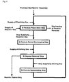
- An object of the present invention is to provide a method for continual preparation of polycrystalline silicon enabling effective removal of silicon deposit formed on the inner wall of the reactor tube of the fluidized bed reactor during the preparation of granular polycrystalline silicon, and thus, enabling a stable, long-term operation of the fluidized bed reactor.
- the present invention provides a method for preparation of polycrystalline silicon using a fluidized bed reactor for preparation of granular polycrystalline silicon, in which a reaction gas outlet of a reaction gas supplying means, that supplies a silicon-containing reaction gas so that silicon deposition may occur while the bed of silicon particles formed inside a reactor tube remains fluidized, is located inside of the bed of silicon particles and, with an outlet end of the reaction gas outlet as the reference height, the upper and lower spaces in the reactor tube are respectively defined as a reaction zone provided for silicon deposition by the reaction gas and a heating zone provided for heating the silicon particles, and which comprises:
- the present invention also relates to a method for preparation of polycrystalline silicon which further comprises (iv) a silicon particle replenishing step, wherein, after removing the silicon deposit and terminating the supply of the etching gas, silicon particles are replenished into the reactor tube to form a bed of silicon particles in the reaction zone.
- the present invention also relates to a method for preparation of polycrystalline silicon wherein the cycle comprising the steps (i), (ii), (iii) and (iv) is repeated.
- the present invention also relates to a method for preparation of polycrystalline silicon in which the fluidized bed reactor comprises a reactor shell which encompasses the reactor tube, and the inner space of the reactor tube is defined as an inner zone where the bed of silicon particles is present and the heating zone and the reaction zone are included, while the space between the reactor tube and the reactor shell is defined as an outer zone where the bed of silicon particles is not present and silicon deposition does not occur.
- the present invention also relates to a method for preparation of polycrystalline silicon in which (i) the silicon particle preparation step comprises the sub-steps of:
- the present invention also relates to a method for preparation of polycrystalline silicon in which an inert gas comprising at least one selected from nitrogen, argon and helium is supplied to the outer zone in order to maintain the outer zone under an inert gas atmosphere.
- an inert gas comprising at least one selected from nitrogen, argon and helium is supplied to the outer zone in order to maintain the outer zone under an inert gas atmosphere.
- the present invention also relates to a method for preparation of polycrystalline silicon in which the difference of the pressure at the outer zone (P o ) and the pressure at the inner zone (P i ) is maintained satisfying the condition of 0 bar ⁇
- the present invention also relates to a method for preparation of polycrystalline silicon in which the etching gas comprises at least one chlorine-containing substance selected from silicon tetrachloride (SiCl 4 ), hydrogen chloride (HCl) and chlorine (Cl 2 ).
- the etching gas comprises at least one chlorine-containing substance selected from silicon tetrachloride (SiCl 4 ), hydrogen chloride (HCl) and chlorine (Cl 2 ).
- the present invention also relates to a method for preparation of polycrystalline silicon in which the etching gas further comprises at least one substance selected from hydrogen, nitrogen, argon and helium.
- the present invention also relates to a method for preparation of polycrystalline silicon in which, in (i) the silicon particle preparation step and/or (iii) the silicon deposit removal step, the absolute pressure at the reaction zone is maintained at in the range of 1-20 bar.
- the present invention also relates to a method for preparation of polycrystalline silicon in which (iii) the silicon deposit removal step comprises the sub-step of removing the silicon deposit formed at the reaction gas outlet of the reaction gas supplying means using the etching gas.
- the present invention also relates to a method for preparation of polycrystalline silicon in which (iii) the silicon deposit removal step is carried out by supplying the etching gas using the reaction gas supplying means and/or an etching gas supplying means the outlet of which is exposed to the reaction zone.
- the present invention also relates to a method for preparation of polycrystalline silicon in which, in (iii) the silicon deposit removal step, a fluidizing gas is supplied to the bed of silicon particles remained in the heating zone using a fluidizing gas supplying means so that the bed of the silicon particles is maintained as a fixed bed in which the particles become immobile or as a fluidized bed in which a part of the particles remains fluidized.
- the present invention also relates to a method for preparation of polycrystalline silicon in which the fluidizing gas comprises at least one substance selected from hydrogen, nitrogen, argon, helium, silicon tetrachloride, trichlorosilane, dichlorosilane and hydrogen chloride.
- the present invention also relates to a method for preparation of polycrystalline silicon in which a fixed bed of packing materials that are not fluidized by the fluidizing gas is formed in addition to the bed of silicon particles at the lower space of the heating zone.
- the present invention also relates to a method for preparation of polycrystalline silicon in which, in (iii) the silicon deposit removal step, an etching-step off-gas including the fluidizing gas being passed through the bed of silicon particles, a non-reacted etching gas and/or an etching reaction product gas is discharged out of the fluidized bed reactor using a gas discharging means.
- the present invention also relates to a method for preparation of polycrystalline silicon in which the reaction gas comprises at least one silicon-containing substance selected from monosilane (SiH 4 ), dichlorosilane (SiH 2 Cl 2 ), trichlorosilane (SiHCl 3 ) and silicon tetrachloride (SiCl 4 ).
- the reaction gas comprises at least one silicon-containing substance selected from monosilane (SiH 4 ), dichlorosilane (SiH 2 Cl 2 ), trichlorosilane (SiHCl 3 ) and silicon tetrachloride (SiCl 4 ).
- the present invention also relates to a method for preparation of polycrystalline silicon in which, in (iii) the silicon deposit removal step, the temperature of a part of the silicon deposit is maintained within the range of 500 ⁇ 1,250 °C.
- the present invention also relates to a method for preparation of polycrystalline silicon in which, in (iii) the silicon deposit removal step, the silicon deposit is heated by a heating means equipped at the inner zone of the reactor tube and/ or at the outer zone.
- the fluidized bed of silicon particles should be formed inside a reactor tube capable of minimizing impurity contamination for preparation of high purity silicon particles.
- silicon deposition reaction (Rd) occurs not only on the surface of hot silicon particles (3) in contact with the reaction gas (11r) but also, inevitably, on the inner wall of the reactor tube (2).
- a reaction gas outlet of a reaction gas supplying means (15r), that supplies a silicon-containing reaction gas (11r) so that silicon deposition may occur while the bed of silicon particles (3) formed inside a reactor tube (2) remains fluidized, is located inside of the bed of silicon particles (3) and, with the outlet end as the reference height, the upper and lower spaces in the reactor tube are respectively defined as a reaction zone (Z r ) provided for the silicon deposition reaction (Rd) by the reaction gas and a heating zone (Zh) provided for heating the silicon particles (3).
- the reaction gas (11r is supplied through the reaction gas supplying means (15r), silicon deposition occurs on the surface of the silicon particles (3) in contact with the reaction gas (11r).
- silicon deposition also occurs at the reactor components encompassing the reaction zone (Z r ), i.e., on the inner wall of the reactor tube (2) and/ or on the surface of the reaction gas outlet of the reaction gas supplying means (15r).
- the thickness of the silicon deposit (D) increases with time, and then the inner diameter of the reaction zone (Z r ) decreases thereby.
- the silicon particle preparation step can be sustained for from a few days to several weeks.
- the operation of silicon deposition is required to be stopped. It is conventional that, after the inside of the reactor is cooled down sufficiently by purging with an inert gas such as hydrogen, nitrogen, argon, helium, etc., all the cooled silicon particles (3) are discharged out of the reactor, the reactor is disassembled, the reactor tube (2) is replaced with a new one, and then the reactor is reassembled for another silicon particles preparation step. On the contrary, the present invention makes it possible to resume silicon deposition after removing the silicon deposit (D) without the need of disassembling the fluidized bed reactor.
- an inert gas such as hydrogen, nitrogen, argon, helium, etc.
- the silicon particles preparation step is followed by a silicon particle partial discharging step, wherein, without requiring the supply of the reaction gas (11r), a part of the silicon particles (3) remaining inside the reactor tube is discharged out of the fluidized bed reactor so that the height of the bed of the residual silicon particles (3) within the reactor tube does not substantially exceed the height of the reaction gas outlet of the reaction gas supplying means (15r).
- a silicon deposit removal step follows the silicon particle partial discharging step.
- an etching gas (11e) which is capable of reacting with the silicon deposit (D) and forming gaseous silicon compounds is supplied into the space of the reaction zone (Z r ), where the bed of silicon particles has been substantially removed, to effectively remove the silicon deposit (D) by etching reaction (R e ).
- the silicon deposit (D) accumulated on the inner wall of the reactor tube (2) is removed, while the silicon deposit (D') accumulated on the surface of the reaction gas outlet of the reaction gas supplying means (15r) may also be removed by its natural contact with the etching gas (11e) introduced.
- the reaction gas outlet of the reaction gas supplying means (15r), which supplies the silicon-containing reaction gas (11r), is located inside of the bed of silicon particles (3) during the silicon particles preparation step, so that silicon deposition may occur in the fluidized bed of silicon particles (3) inside the reactor tube (2).
- the upper and lower spaces in the reactor tube (2) are respectively defined as a reaction zone (Z r ) provided for silicon deposition reaction (Rd) by the reaction gas (11r) and a heating zone (Zh) provided for heating the silicon particles (3).
- the silicon particle preparation step in which silicon product particles are prepared by silicon deposition on the surface of the silicon particles (3) in contact with the reaction gas (11r) supplied by the reaction gas supplying means (15r), can be sustained as long as possible in the fluidized bed reactor.
- the silicon deposit (D) is also formed and accumulated on the inner wall of the reactor tube (2) encompassing the reaction zone (Zr).
- the present invention comprises a silicon particle partial discharging step in which, without requiring the supply of the reaction gas (11r), a part of the silicon particles (3) is discharged out of the fluidized bed reactor, so that the height of the bed of silicon particles (3) remaining inside the reactor tube (2) does not exceed the height of the outlet, and a silicon deposit removal step in which an etching gas (11e), that reacts with the silicon deposit (D) to form gaseous silicon compounds, is supplied into the space of the reaction zone (Z r ) for removing the silicon deposit (D).
- an etching gas (11e) that reacts with the silicon deposit (D) to form gaseous silicon compounds
- a silicon particle replenishing step follows in which silicon particles (3) substantially corresponding to the amount discharged out of the reactor during the silicon particle partial discharging step are replenished into the reactor tube (2) to form a bed of silicon particles (3) in the reaction zone (Z r ).
- the silicon particle preparation step in which silicon deposition occurs on the surface of fluidized silicon particles (3) by supplying the reaction gas (11r) into the reaction zone (Z r ) using the reaction gas supplying means (15r), can be resumed.
- the present invention may ultimately provide a method for continual preparation of polycrystalline silicon following the sequential steps of: the step in which the reaction gas is supplied to the reaction zone (Z r ) of the reactor tube (2), so that silicon particles are prepared by silicon deposition on the surface of the silicon particles (3) while the silicon deposit (D) is accumulated; the step in which, without requiring the supply of the reaction gas, a part of the silicon particles is discharged out of the fluidized bed reactor; the step in which the etching gas is supplied into the reaction zone (Z r ) to remove the silicon deposit (D); and the step in which, after the supply of the etching gas is terminated, silicon particles are replenished to the reaction zone (Z r ) inside the reactor tube (2).
- the rate of the etching reaction (R e ) of the silicon deposit (D) with the etching gas (11e) becomes very high.
- the silicon deposit removal step may be completed very rapidly within from a few minutes to several hours.
- the amount of the silicon particles to be discharged during the silicon particle partial discharging step is smaller than the total amount of the silicon particles residing in the reactor tube (2) during the silicon particle preparation step, the time required for the silicon deposit removal step and the silicon particle replenishing step is very short as compared with that required for the silicon particle preparation step and is of little burden to the productivity of the reactor.
- the reactor needs not be disassembled and the reactor tube (2) can be continuously used although the silicon deposit (D) is accumulated on the inner wall of the reactor tube (2) or on other components of the reactor during the silicon particle preparation step. This is possible because the silicon deposit (D) can be removed quickly without the need of disassembling the fluidized bed reactor. Then, through the silicon particle replenishing step, it is also possible to execute silicon deposition cycles in a repeated manner by quickly resuming the silicon particle preparation step.
- the reactor components that contact the hot silicon particles (4) and are exposed to the reaction gas (11r) during the silicon particle preparation step include such solid surfaces the inner wall of the reactor tube (2) and/or the reaction gas outlet of the reaction gas supplying means (15r).
- the etching gas (11e) is supplied to the reaction zone (Z r ) during the silicon deposit removal step, not only the silicon deposit (D) accumulated on the inner wall of the reactor tube (2) but also the silicon deposit (D') accumulated at the reaction gas outlet of the reaction gas supplying means (15r) is exposed to the etching gas (11e) and removed by etching reaction (R e ).
- the silicon deposit (D) accumulated on the inner wall of the reactor tube (2) but also the silicon deposit (D') accumulated at the reaction gas outlet of the reaction gas supplying means (15r) can be removed by the etching gas (11e).
- the present invention can be applied to any type of fluidized bed reactor in which the bed of the silicon particles (3) is divided into the reaction zone (Z r ) and the heating zone (Z h ), with the outlet end of the reaction gas supplying means (15r) being taken as the reference height.
- the present invention can be widely applied in the preparation of granular polycrystalline silicon.
- a reactor tube (2) may be installed inside a reactor shell (1) having a superior mechanical strength, so that the reactor shell (1) encompasses the reactor tube (2).
- the inner space of the reactor tube (2) is defined as an inner zone (4) where the bed of silicon particles (3) is present.
- the inner zone (4) includes a heating zone (Z h ) and a reaction zone (Z r ).
- the space between the reactor tube (2) and the reactor shell (1) is defined as an outer zone (5) where the bed of silicon particles is not present and silicon deposition reaction (R d ) does not occur.
- the silicon particle preparation step executed using the fluidized bed reactor may comprise the sub-steps of: supplying a fluidizing gas (10) to the bed of silicon particles (3) in the heating zone (Z h ) using a fluidizing gas supplying means (14) so that the bed of silicon particles (3) formed in the reaction zone (Z r ) becomes fluidized; heating the silicon particles (3) with a heating means (8a, 8b) equipped at the inner zone (4) and/or the outer zone (5) of the reactor tube (2); discharging a part of the silicon particles (3b) prepared in the inner zone (4) out of the fluidized bed reactor using a particle discharging means (16); and discharging an off-gas (13r) comprising the fluidizing gas (10), which passes through the bed of silicon particles, a non-reacted reaction gas and a byproduct gas out of the fluidized bed reactor using a gas discharging means (17).
- the silicon deposit removal step it is possible to remove the silicon deposit by supplying the etching gas (11e) to the reaction zone (Z r ) using a reaction gas supplying means (15r) and/or an etching gas supplying means (15e) the outlet of which is exposed to the reaction zone (Z r ).
- the etching gas (11e) may be supplied to the reaction zone (Z r ) instead of the reaction gas (11r) using the reaction gas supplying means (15r) as an etching gas supplying means (15e), as schematically illustrated in Fig. 3 , in order to carry out the silicon deposit removal step.
- the reaction gas supplying means (15r), i.e., the etching gas supplying means (15e) may be constructed such that the reaction gas (11r) and the etching gas (11e) can pass through the same route or nozzles, or such that the reaction gas (11r) and the etching gas (11e) can pass through different routes or nozzles.
- the etching gas (11e) may be supplied using an etching gas supplying means (15e) which is equipped independently of the reaction gas supplying means (15r) in the inner zone (4) of the fluidized bed reactor and the outlet of which is exposed to the reaction zone (Z r ).
- the silicon deposit removal step may be carried out by supplying the etching gas (11e) to reaction zone (Z r ) using both the reaction gas supplying means (15r) and the etching gas supplying means (15e).
- the present invention is characterized in that the bed of silicon particles (3) is always present in part or whole of the heating zone (Z h ) inside the reactor tube (2) in all the steps comprised in each silicon deposition cycle, that is, (i) the silicon particle preparation step; (ii) the silicon particle partial discharging step; (iii) the silicon deposit removal step; and (iv) the silicon particle replenishing step.
- the bed of silicon particles (3) be formed not only in the heating zone (Z h ) but also in the reaction zone (Z r ) and that the silicon particles (3) in the two zones can be mixed with each other while at least the silicon particles (3) present in the reaction zone (Z r ) remain fluidized, as schematically illustrated in Fig. 2 or Fig. 4 .
- the bed of the silicon particles (3) present in the heating zone (Z h ) may be a fixed bed, but it is preferred that a fluidizing gas (10) be supplied by a fluidizing gas supplying means (14) so that at least the particles present at the upper part of the heating zone (Z h ) remain fluidized for effective exchange of the silicon particles between the two zones (Z r , Z h ).
- the height of the bed of silicon particles (3) within the reactor tube (2) becomes lowered with time to or below the height of the reaction gas outlet of the reaction gas supplying means (15r).
- an appropriate amount of the fluidizing gas (10) may be supplied for efficient discharge of the particles.
- Fluidization of the silicon particles (3) as mentioned in the present description means the possibility of a change in the spatial position of the silicon particles with time caused by the flow of gas through the particles, the movement and evolution of gas bubbles, and/or the motion of neighboring particles.
- the whole or part of the bed of silicon particles present in the heating zone (Z h ) may remain as fixed or partly fluidized by supplying the fluidizing gas (10) by the fluidizing gas supplying means (14).
- the whole or a part of the bed of silicon particles present in the heating zone (Z h ) may remain as fixed or partly fluidized by supplying the fluidizing gas (10) by the fluidizing gas supplying means (14).
- an etching-step off-gas (13e) comprising the fluidizing gas being passed through the bed of silicon particles (3) be remained, and a non-reacted etching gas and/or an etching reaction product gas be discharged out of the fluidized bed reactor using a gas discharging means (17) as schematically illustrated in Fig. 5 .
- the fluidizing gas (10) used in the whole or a part of the silicon deposition cycles in accordance with the present invention passes through the bed of silicon particles (3) residing in the heating zone (Z h ) as illustrated in Figs. 2-7 , it should be purified to avoid contamination of the silicon particles.
- the fluidizing gas (10) is one not reacting with the silicon particles and is selected from hydrogen, nitrogen, argon and helium.
- the fluidizing gas (10) may further comprise a chlorine compound more dense and viscous than the non-reactive gas components, which may be obtained during the preparation of polycrystalline silicon or contained in the reaction byproduct gas, such as silicon tetrachloride (SiCl 4 ), trichlorosilane (SiHCl 3 ), dichlorosilane (SiH 2 Cl 2 ), hydrogen chloride (HCl), etc.
- a chlorine compound more dense and viscous than the non-reactive gas components, which may be obtained during the preparation of polycrystalline silicon or contained in the reaction byproduct gas, such as silicon tetrachloride (SiCl 4 ), trichlorosilane (SiHCl 3 ), dichlorosilane (SiH 2 Cl 2 ), hydrogen chloride (HCl), etc.
- the fluidizing gas (10) used in the present invention may comprise at least one substance selected from hydrogen (H 2 ), nitrogen (N 2 ), argon (Ar), helium (He), silicon tetrachloride (SiCl 4 ), trichlorosilane (SiHCl 3 ), dichlorosilane (SiH 2 Cl 2 ) and hydrogen chloride (HCl).
- the fluidizing gas (10) mentioned in the present description represents a gas supplied by the fluidizing gas supplying means (14) into the bed of silicon particles (3) residing in the heating zone (Zh).
- the supply rate of the fluidizing gas (10) can be adjusted differently at each step of a silicon deposition cycle. Accordingly, the supply of the fluidizing gas (10) does not necessarily cause the fluidization of the silicon particles (3).
- the fluidized bed of silicon particles (3) in the reaction zone (Z r ) and/or the heating zone (Z h ) a considerable amount of fluidizing gas (10) has to be supplied, and the load of the heating means (8a, 8b) for heating the gas increases accordingly.
- a considerable amount of fluidizing gas (10) has to be supplied, and the load of the heating means (8a, 8b) for heating the gas increases accordingly.
- it is optional to construct the fluidized bed reactor such that a fixed bed, i.e., a packed bed of non-fluidizable packing materials (22) is formed in addition to the bed of silicon particles (3) at the lower part of the heating zone (Z h ), so that the supply of the fluidizing gas (10) per unit time may not become excessive.
- the packing materials (22) In order to form the fixed bed of the packing materials (22), it is required that the average unit weight of the packing materials be at least 5-10 times higher than that of the silicon particles, the fixed bed be not physically deformed by the movement or fluidization of the silicon particles (3) and the material be selected so that impurity contamination of the silicon particles (3) can be minimized. While the silicon deposition cycles are repeated, the packing materials (22) remain almost stationary without being moved along with the silicon particles (3) or discharged. Also, they can perform the function of a gas distributing means for distributing the fluidizing gas (10) more uniformly at the lower part of the heating zone (Z h ). Further, their surface can indirectly increase the heat transfer area of the heating means (8a) at the heating zone (Z h ) when they are installed together with a heating means (8a).
- the reaction gas (11r) supplied to the reaction zone (Z r ) during the silicon particle preparation step should comprise a silicon-containing substance, so that silicon deposition may occur to yield granular polycrystalline silicon.
- the reaction gas (11r) may comprise at least one substance selected from monosilane (SiH 4 ), dichlorosilane (SiH 2 Cl 2 ), trichlorosilane (SiHCl 3 ) and silicon tetrachloride (SiCl 4 ).
- the reaction gas (11r) may comprise only the afore-mentioned silicon deposition source material. However, it may further comprise at least one gas component selected from hydrogen, nitrogen, argon, helium and hydrogen chloride (HCl).
- the reaction gas (11r) contributes to the fluidization of the silicon particles (3) in the reaction zone (Z r ) together with the fluidizing gas (10).
- the etching gas (11e), which is supplied to the reaction zone (Z r ) to remove the silicon deposit (D) by forming gaseous silicon compounds through its reaction with the silicon deposit (D) during the silicon deposit removal step, may comprise at least one chlorine-containing substance selected from silicon tetrachloride (SiCl 4 ), hydrogen chloride (HCl) and chlorine (Cl 2 ).
- the etching reaction (R e ) triggered by the etching gas (11e) may comprise: (1) trichlorosilane formation from a mixture of silicon tetrachloride/silicon metal/hydrogen; (2) chlorosilane formation from a mixture of silicon metal/ hydrogen chloride or silicon metal/ hydrogen chloride/ hydrogen; and/ or (3) chlorosilane formation from a mixture of silicon metal/chlorine.
- the chlorine-containing substance there are many compounds that can remove the silicon deposit through their reaction with silicon. But, the chlorine-containing substance is preferred in the present invention to prevent any impurity contamination by limiting the chemical reactions involved in the repeated silicon deposition cycles within the Si-H-Cl system.
- the etching gas (11e) used in the present invention may comprise only the chlorine-containing substance. But, it may further comprise at least one substance selected from hydrogen, nitrogen, argon and helium. If the content of the chlorine-containing substance in the etching gas mixture comprising the diluent gas is too low, the rate of etching reaction decreases. Thus, it is preferred not to dilute the etching gas supplied in the silicon deposit removal step too much. For example, if hydrogen chloride is used as the chlorine-containing substance, it is preferred that the molar concentration of the diluent gas do not exceed about 2-3 times that of hydrogen chloride.
- the reaction temperature for silicon deposition or the temperature of the silicon particles, should be maintained high. While the reaction temperature for monosilane is about 600-850 °C, the temperature for trichlorosilane, which is more widely used for commercial purpose, is as high as about 900-1,150 °C.
- the temperature of the part of the silicon deposit (D) be kept within the range of from 500 to 1,250 °C in order to significantly increase the rate of the etching reaction (R e ).
- the etching reaction (R e ) of the silicon deposit (D) composed of high purity silicon does not begin very quickly.
- the rate of the etching reaction (R e ) is very high, but it is highly likely that the wall of the reactor tube (2) covered by the silicon deposit (D) be physically damaged by the reaction heat generated.
- Heating of the silicon deposit (D) using the heating means (8a, 8b) may be carried out not only directly by radiation heating, but also indirectly by the fluidizing gas (10), the etching gas (11e) and/or the bed of silicon particles (3) heated by the heating means (8a, 8b).
- the silicon deposit (D) Once part of the silicon deposit (D) is heated to 500-1,250 °C, it is quickly removed by the etching reaction (R e ) with the etching gas (11e) and the remaining silicon deposit (D) may be heated in situ by the reaction heat of the etching reaction (R e ). Thus, it is not necessary to uniformly heat the whole deposit.
- the absolute pressure in the reaction zone (Z r ) be maintained within 1-20 bar during the silicon particle preparation step and/or the silicon deposit removal step. If absolute pressure (P i ) in the reaction zone (Z r ) is lower than 1 bar, the rate of silicon deposition or etching reaction (R e ) is not high enough, making the process unproductive.
- the absolute pressure (P i ) in the reaction zone (Z r ) be selected in the range of from about 1 to 20 bar.
- a fluidized bed reactor which may effectively carry out (i) the silicon particle preparation step; (ii) the silicon particle partial discharging step; (iii) the silicon deposit removal step; and (iv) the silicon particle replenishing step in accordance with the present invention and may improve the productivity in preparing polycrystalline silicon particles by repeating the silicon deposition cycles in a continual manner.
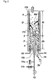
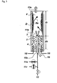
- Fig. 6 and Fig. 7 illustrate respectively in a comprehensive way the schematics of the embodiments of a fluidized bed reactor that can be used to prepare granular polycrystalline silicon by repeating silicon deposition cycles.
- the inner space of the reactor is isolated from the outside of the reactor by the reactor shell (1).
- the reactor shell (1) encompasses the reactor tube (2) which is installed vertically in the inner space of the reactor. That is, the reactor tube (2) is installed vertically inside the reactor shell (1), so that the reactor shell (1) encompasses the reactor tube (2).
- the inner space of the reactor tube (2) is defined as an inner zone (4) in which the bed of silicon particles (3) is present and silicon deposition occurs. Further, the space between the reactor tube (2) and the reactor shell (1) is defined as an outer zone (5) in which the bed of silicon particles (3) is not present and silicon deposition does not occur.
- the reactor shell (1) may be made of a metallic material with reliable mechanical strength and easy processability such as carbon steel, stainless steel or other alloy steels. As set forth in Fig. 6 and Fig. 7 , the reactor shell (1) may be composed of several components (1a, 1b, 1c, 1d) for convenience in fabrication, assembly and disassembly.
- the components of the reactor shell (1) may be in the form of a cylindrical pipe, a flange, a tube with fittings, a plate, a cone, an ellipsoid or a double-wall jacket with a cooling medium flowing in between the walls, etc.
- the inner surface of each component may be coated with a protective layer or be additionally installed with a protective wall in the form of tube or shaped liner, which may be made of a metallic material or a non-metallic material such as organic polymer, ceramic or quartz, etc.
- Some of the components of the reactor shell (1) are preferred to be maintained below a certain temperature by using a cooling medium such as water, oil, gas and air for protecting the equipment or operators, or for preventing any thermal expansion in equipment or a safety accident.
- a cooling medium such as water, oil, gas and air
- the components that need to be cooled are preferably designed to comprise a coolant-circulating means at their inner or outer walls.
- an insulation material may be equipped on the outer surface of the reactor shell (1) for protection of operators and prevention of excessive heat loss.
- the reactor tube (2) may be of any shape only if it can be hold by the reactor shell (1) in such a manner that it can separate the inner space of the reactor shell (1) into an inner zone (4) and an outer zone (5).
- the reactor tube (2) may have the form of a simple straight tube as in Fig. 6 , a shaped tube as in Fig. 7 , a cone or an ellipsoid, and either one end or both ends of the reactor tube (2) may be formed into a flange shape.
- the reactor tube (2) may comprise a plurality of components and some of these components may be installed in the form of a liner along the inner wall of the reactor shell (1).
- the reactor tube (2) is preferably made of an inorganic material, which is stable at a relatively high temperature, such as quartz, silica, silicon nitride, boron nitride, silicon carbide, graphite, silicon, glassy carbon and composite material thereof.
- a carbon-containing material such as silicon carbide, graphite, glassy carbon, etc., may generate carbon impurity and contaminate the polycrystalline silicon particles.
- the reactor tube (2) is made of a carbon-containing material
- the inner wall of the reactor tube (2) is preferred to be coated or lined with materials such as silicon, silica, quartz or silicon nitride.
- the reactor tube (2) may be structured in a multi-layered form. Therefore, the reactor tube (2) is of one-layered or multilayered structure in the thickness direction, each layer of which is made of a different material.
- the selection of a sealing means (41a, 41b) may be important for the reactor tube (2) to be safely hold by the reactor shell (1).
- the sealing means are preferred to endure the high temperature of about 200 °C or above and may be selected from organic polymers, graphites, silicas, ceramics, metals or composite materials thereof.
- the sealing means (41a, 41b) may be installed not too firmly so that the possibility of cracking of the reactor tube (2) can be lowered during assembly, operation and disassembly.
- the partition of the inner space of the reactor shell (1) by the reactor tube (2) may prevent the silicon particles (3) in the inner zone (4) from leaking into the outer zone (5) and differentiate the function and condition between the inner zone (4) and the outer zone (5).
- the silicon particles (3) present in the inner zone (4) should be heated to a temperature required for silicon deposition by the heating means (8a, 8b) equipped at the inner zone (4) and/or the outer zone (5).
- One or a plurality of heating means (8a, 8b) may be installed in the inner zone (4) and/or the outer zone (5) in various manners.
- a heating means may be installed only in the inner zone (4) or in the outer zone (5) as illustrated in Fig. 6 in a comprehensive manner.
- a plurality of heating means may be installed in both zones, or only in the outer zone 5 as illustrated in Fig. 7 .
- a plurality of heating means (8a, 8b) may be installed only in the inner zone (4). Otherwise, a single or a plurality of heating means may be installed in the outer zone 5 only.
- the electric energy supplying means (9), which connects the heating means (8a, 8b) in the reactor with an electric source (E) located outside the reactor, may comprise various types of electrically conducting materials as followings: (i) a well conducting metallic material in the form of a cable, a bar, a rod, a shaped body, a socket, a coupler, etc.; a graphite, a ceramic (e.g., silicon carbide), a metal or a mixture thereof in the form of various electrodes that connect the power lines from the electric source (E) with the heating means.
- the electric energy supplying means can be prepared by extending a part of the heating means (8a, 8b).
- electrical insulation is also important besides the mechanical sealing for preventing gas leak.
- the fluidized bed of the silicon particles (3) which are moved by gas flow, is formed inside the reactor tube (2), at least in the reaction zone (Z r ), and silicon deposition occurs on the surface of the fluidizing silicon particles resulting in preparation of silicon particles, i.e., granular silicon product.
- a fluidizing gas supplying means (14, 14') which supplies the fluidizing gas (10) to the bed of silicon particles and a reaction gas supplying means (15r) which supplies the silicon-containing reaction gas (11r) are installed as coupled with the reactor shell (1b).
- An etching gas supplying means (15e) may be installed at the fluidized bed reactor, as illustrated in Fig. 4 and Fig. 5 .
- the reaction gas supplying means (15r) may be used to supply the etching gas (11e) during the silicon deposit removal step, as illustrated in Fig. 2 and Fig. 3 .
- the reaction gas supplying means (15r) may have a simple structure, as illustrated in Figs. 2-7 . But, because the reaction gas (11r) is sensitive to high temperature, various and complicated structures may be adopted [see U.S. Patent No. 5,810,934 (1998 ); U.S. Patent No. 6,541,377 (2003 )].
- reaction gas supplying means (15r) When the reaction gas supplying means (15r) is used to supply the etching gas (11e) during the silicon deposit removal step, the reaction gas (11r) and the etching gas (11e) may be rendered to pass the same paths or nozzles, as illustrated in Fig. 2 , Fig. 3 , Fig. 6 and Fig. 7 .
- the reaction gas supplying means (15r) may have a plurality of gas paths or nozzles, so that the reaction gas (11r) and the etching gas (11e) can pass through different paths or nozzles.
- Each of the fluidizing gas supplying means (14, 14') and the reaction gas supplying means (15r) may be composed of such components as a tube or nozzle, a chamber, a flange, a fitting, a gasket, etc.
- the components which may contact the silicon particles (3) inside the reactor shell (1), particularly at the lower part of the inner zone (4), are preferably composed of a tube, a liner or a shaped body made of the inorganic material used to make the reactor tube (2).
- a gas distributing means (19) which distributes the fluidizing gas (10), is preferably equipped along with the fluidizing gas supplying means (14, 14') and the reaction gas supplying means (15r).
- the gas distributing means (19) may be in the form of a multi-hole or porous distribution plate, a packing material (22), a nozzle, a gas distributor shaped body or a combination thereof, without being limited to a specific form.
- the components of the gas distributing means (19) which may contact the silicon particles (3), e.g., its upper surface, are preferably made of an inorganic material used to make the reactor tube (2).
- the reaction gas outlet of the reaction gas supplying means (15r), which introduces or injects the reaction gas (11r) into the fluidized bed, is preferably positioned higher than the upper surface of the gas distributing means (19), in order to prevent silicon deposition on the upper surface of the gas distributing means (19).
- the fluidizing gas (10), required to form the fluidized bed of the silicon particles (3) at least in the reaction zone (Z r ), may be supplied in a variety of ways, depending on the construction of the fluidizing gas supplying means (14, 14').
- the fluidizing gas (10) may be supplied by a fluidizing gas supplying means (14, 14') comprising a gas chamber (14') is formed below a plate-type gas distributing means (19) and is coupled with the reactor shell (1), as illustrated in Figs. 4 , 5 and 6 .
- a fluidizing gas supplying means (14, 14') comprising a gas chamber (14') is formed below a plate-type gas distributing means (19) and is coupled with the reactor shell (1), as illustrated in Figs. 4 , 5 and 6 .
- the fixed bed of the packing materials (22), which is not moved by the fluidizing gas (10), may be utilized as a part of the gas distributing means.
- a fluidizing gas (10) may be supplied by a fluidizing gas supplying means (14) coupled with the reactor shell (1) so that one or a plurality of fluidizing gas nozzle outlet may be positioned in between the gas distributing means (19) that comprises a fixed bed of packing materials that will not be contained in the fluidizing granular silicon product (3b).
- the gas distributing means (19) may comprise at least two components selected from a distribution plate, a nozzle, packing materials (22) and a gas distributor shaped body.
- the gas distributing means (19) may comprise the fixed bed of the packing materials (22) other than the silicon particles (3) to be contained in the silicon product particles (3b).
- the packing materials (22) have such a large size or sufficient unit mass as not to be moved by the flow of the fluidizing gas (10). They may have the shape of a sphere, an oval, a pellet, a nugget, a tube, a rod or a ring.
- the packing material (22) is a high purity silicon material, having an average diameter in the range of from 5 to 50 mm and an average unit weight of at least about 5-10 times that of an average-sized silicon particle (3), or an inorganic material that can be used for or layered on the reactor tube (2).
- the fixed bed of the packing material (22) which is not mobile by the flow of the fluidizing gas (10) constitutes the gas distributing means (19)
- the fixed bed is preferably formed at a height lower than the reaction gas outlet of the reaction gas supplying means (15r), that is, at the lower part of the heating zone (Z h ).
- the fixed bed is formed in the heating zone (Z h )
- movement of the silicon particles and flow of the fluidizing gas may occur through the space between the packing materials (22).
- the heat transferred from the bed of the silicon particles (3) heated by the heating means (8a, 8b) downward to the lower part of the reactor may be utilized for pre-heating the fluidizing gas (10).
- the fluidizing silicon particles (3) heated directly or indirectly by the heating means (8a, 8b) can contact and be exposed to the reaction gas (11r) supplied by the reaction gas supplying means (15r) while residing temporarily or over a substantial period of time or with a regular or irregular fluctuating frequency in the reaction zone (Z r ).
- silicon deposition occurs on the inner wall of the reactor tube (2), which encompasses the reaction zone (Z r ) and contacts the hot silicon particles (3) and reaction gas (11r), and is accumulated thereon to form a silicon deposit (D), which increases in thickness and volume as time passes.
- the gas distributing means (19) and the fluidizing gas supplying means (14) enable supply of the fluidizing gas (10) to the inner zone (4), particularly to the heating zone (Z h ).
- the fluidizing gas (10) it is not necessary to supply the fluidizing gas (10) in large quantity during the other steps, because the silicon particles need not always be maintained fluidized in the inner zone (4).
- silicon particles prepared during the silicon particle preparation step it is preferable to discharge or withdraw a part of the silicon particles prepared during the silicon particle preparation step from the inner zone (4) of the fluidized bed reactor and replenish silicon seed crystals (3a) to the inner zone (4) in order to maintain the number and average particle diameter of the silicon particles (3) as constant as possible in the inner zone (4).
- a particle discharging means (16) for discharging the polycrystalline silicon particles needs to be installed as coupled with the reactor shell (1).
- the discharge pipe of the particle discharging means (16) may be assembled along with the reaction gas supplying means (15r) as in Fig. 6 or may be installed independently of the reaction gas supplying means (15r) as in Fig. 4 , 5 or 7 , so that the silicon particles (3b) can be discharged from the inner zone (4) at the right time, continuously, periodically or intermittently.
- an independent space may be coupled with the reactor shell (1), so that the silicon particles (3b) can be cooled before being discharged out of the reactor, while remaining at a part or at the bottom of the space of the fluidizing gas supplying means (14') as shown in Fig. 6 .
- a part of the silicon particles discharged from the inner zone (4) during the silicon particle preparation step, or the silicon product particles (3b) may be transferred to a polycrystalline silicon product storage means or handling means directly connected with the reactor.
- the small sized ones can be readily utilized as seed crystals (3a). Accordingly, it is also possible to transfer the silicon product particles (3b) discharged from the inner zone (4) to a classifying means that can classify the particles depending on size, in order to transfer large particles to the polycrystalline silicon product storage means or handling means and use small particles as seed crystals (3a).
- the silicon particles (3b) are preferably cooled while being discharged by the particle discharging means (16) because the reactor inner zone (4) or the fluidized bed (4a) of silicon particles is hot.
- hydrogen, nitrogen, argon, helium or other gas may be flown through the particle discharging means (16) or a cooling medium such as water, oil, gas, etc., may be circulated along the wall of the particle discharging means (16).
- the particle discharging means (16) may be equipped as coupled with the inside of the reactor shell (1) (e.g., 14' of Fig. 6 ) or the bottom of the reactor shell (e.g., 1b of Fig. 6 or Fig. 7 ) in order to provide a sufficient space, so that the silicon particles (3b) are discharged out of the fluidized bed reactor after being sufficiently cooled while remaining in the fluidized bed (4a).
- the particle discharging means (16) It is required to prevent the silicon product particles (3b) from being contaminated by impurities while they are discharged out of the reactor by the particle discharging means (16).
- the components of the particle discharging means (16) which can be exposed to or contact the hot silicon product particles (3b), in the form of a tube, a liner or a shaped body made of the inorganic material that may be used for the reactor tube (2).
- Such components of the particle discharging means (16) need to be fixed as coupled with the reactor shell (1) and/or a protection tube made of a metallic material.
- the components of the particle discharging means (16) which contact substantially cooled silicon particles or the wall of which can be cooled by a cooling medium, may consists of a tube, a liner or a shaped body made of a metallic material coated or lined with a fluorine-containing polymer material on the inner wall.
- the silicon product particles (3b) may be discharged continuously, periodically or intermittently from the reactor inner zone (4) to the polycrystalline silicon product storage means or handling means by the particle discharging means (16).
- the components of the classifying means that contact the silicon product particles (3b) is preferably made of a material used in the particle discharging means (16) or a pure polymeric material with no additive or filler added.
- the particle discharging means (16) may be also utilized in the silicon particle partial discharging step as a means of discharging a part of the silicon particles (3) from the inner zone (4), so that the height of the bed of the remaining silicon particles (3) cannot exceed that of the outlet of the reaction gas supplying means (15r).
- the partial discharging step can also be performed by discharging a part of the silicon particles (3) from the inner zone (4) through the reaction gas supplying means (15r) on behalf of the particle discharging means (16).
- a container for temporarily storing the silicon particles (3) may be equipped at the bottom of the reaction gas supplying means (15r), so that the silicon particles remaining in the reaction zone (Z r ) can fall into the container with an appropriate amount of an inert gas, instead of the reaction gas (11r), being supplied into the inner zone (4). Meanwhile, part of the silicon particles (3) remaining in the inner zone (4) may be discharged to the container through the reaction gas supplying means (15r) by supplying the fluidizing gas (10) to the heating zone (Z h ), so that the height of the bed of the silicon particles can be lowered down to a predetermined value.
- the gas discharging means (17) With the reactor shell (1d) for discharging an off-gas (13), including the fluidizing gas being passed through the fluidized bed (4a), a non-reacted reaction gas and a byproduct gas, out of the fluidized bed reactor via the top of the inner zone (4c).
- Fine silicon powders or high-molecular-weight reaction byproducts entrained by the off-gas (13) are separated by a off-gas treating means (34).
- the off-gas treating means (34) selected among a cyclone, a filter, a packing tower, a scrubber, a centrifuge, etc., may be equipped either outside of the reactor shell (1) or at the upper space (4c) of the inner zone within the reactor shell (1), as illustrated in Fig. 6 or Fig. 7 .
- the silicon particles separated by the off-gas treating means (34) may be recycled to the fluidized bed (4a) in the inner zone of the reactor for use as seed crystals (3a) or may be utilized for other purposes.
- the gas discharging means (17) enables discharging of the fluidizing gas (10), the inert gas supplied to the inner zone (4) and/ or the gas components remaining in the inner zone (4) not only during the silicon particle preparation step, but also during the silicon particle partial discharging step, the silicon deposit removal step and the silicon particle replenishing step. Particularly, during the silicon deposit removal step, a mixture of a non-reacted etching gas, etching reaction (R e ) byproducts, and/or the fluidizing gas (10), etc., may be discharged by the gas discharging means (17).
- the number of silicon particles comprising the fluidized bed (4a) and the average particle size thereof within a certain range.
- the silicon particles or powders of an appropriate size separated by the off-gas treating means (34) can be used as seed crystal, the amount is restricted.
- a further preparation or manufacture of silicon seed crystals is inevitable for continuous production of silicon particles.
- a way of separating small silicon particles from the product particles (3b) and utilizing them as seed crystals (3a) can be considered.
- the process of separating the seed crystals (3a) from the product particles (3b) outside the fluidized bed reactor is complicated and vulnerable to contamination by impurities.
- a classifying means may be equipped at the particle discharge path of the particle discharging means (16), so that small silicon particles can be recycled back into the fluidized bed (4a) by the gas flowing upward for cooling down the product particles (3b) during their discharge, thereby reducing the requirement of seed crystal supply, increasing the average particle size of the product particles (3b) and reducing particle size distribution in the product particles.
- silicon seed crystals are prepared by pulverizing some of the silicon product particles (3b) discharged by the particle discharging means (16) with a pulverizing apparatus.
- the seed crystals (3a) may be supplied continuously, periodically or intermittently at the right time into the reactor inner zone (4) through a seed crystal supplying means (18) installed as coupled with the reactor shell (1d), as illustrated in Fig. 6 .
- This method is advantageous in that the size and feeding rate of the seed crystals (3a) can be adjusted as required.
- an independent pulverizing apparatus is required.
- the silicon particles may be pulverized into seed crystals inside the fluidized bed (4a) by using the reaction gas outlet nozzle of the reaction gas supplying means (15r) or an additionally installed gas nozzle for a high-speed gas jet inside the fluidized bed allowing particle pulverization.
- This method is economical because no additional pulverizing apparatus is required.
- it is disadvantageous in that it is difficult to control the size and rate of generation of the seed crystals.
- the silicon particles discharged during the silicon particle partial discharging step may be contained in product particles (3b) or put aside and supplied to the inner zone (4) through the seed crystal supplying means (18) during the silicon particle replenishing step. Otherwise, instead of the silicon particles discharged during the silicon particle partial discharging step, the independently prepared silicon seed crystals (3a) may be supplied to the inner zone (4) through the seed crystal supplying means (18) during the silicon particle replenishing step.
- the inner zone (4) comprises all spaces required for forming the bed of silicon particles (3) wherein the fluidizing gas (10) and the reaction gas (11r) are supplied and silicon deposition occurs, and required for flowing and discharging of the off-gas (13) including the fluidizing gas, a non-reacted reaction gas and a byproduct gas. Therefore, the inner zone (4) plays an important role in producing polycrystalline silicon particles by silicon deposition in the fluidized bed of silicon particles (3).
- the outer zone (5) is an independently formed space in between the outer wall of the reactor tube (2) and the reactor shell (1), in which the bed of silicon particles (3) is not present and silicon deposition does not occur.
- the outer zone (5) as mentioned in this description is the space of the inner space of the reactor shell (1) excluding the inner zone (4) or is formed in between the reactor tube (2) and the reactor shell (1).
- an inert gas is supplied to the outer zone (5) to maintain the outer zone under an insert gas atmosphere.
- the reason of maintaining the outer zone (5) under an inert gas atmosphere and several important roles of the outer zone (5) are as follows.
- the outer zone (5) provides a space for protecting the reactor tube (2), which is accomplished by maintaining a pressure difference between the inner zone (4) and the outer zone (5) within a certain range.
- the outer zone (5) provides a space for installing an insulation material (6) for preventing or reducing heat loss from the reactor.
- the outer zone (5) provides a space for installing a heating means, if required, around the reactor tube (2) for heating the reactor.
- the outer zone (5) provides a space for maintaining a substantially inert gas atmosphere outside the reactor tube (2) to prevent dangerous gas containing oxygen and impurities from being introduced into the inner zone (4), and for safely installing and maintaining the reactor tube (2) inside the reactor shell (1).
- the outer zone (5) allows a real-time monitoring of the status of the reactor tube (2) during operation.
- the analysis or measurement of the outer-zone gas sample from the outer zone connection means (28, 28a, 28b) may reveal the presence or concentration of a gas component that may exist in the inner zone (4), the change of which may indirectly reveal an accident at the reactor tube.
- the outer zone (5) may provide a space for installing a heating means for heating the silicon deposit (D) accumulated on the inner wall of the reactor tube (2) so that the deposit can be removed rapidly by introducing an etching gas (lIe) into the reaction zone (Zr).
- the outer zone (5) facilitates assembly and disassembly of the reactor tube (2) and the inner zone (4).
- the space of the outer zone may be partitioned into several sections in an up-and-down and/or a radial or circumferential direction, utilizing one or more of tubes, plates, shaped bodies or fittings as partitioning means.
- the divided sections are preferred to spatially communicate with each other while having substantially the same atmospheric condition and pressure.
- An insulation material (6) which may be installed in the outer zone (5) for greatly reducing heat transfer via radiation or conduction, may be selected from industrially acceptable inorganic materials in the form of a cylinder, a block, fabric, a blanket, a felt, a foamed product, or a packing filler material.
- the heating means (8) which is connected to an electric energy supplying means (9) coupled with the reactor shell (1) for maintaining the reaction temperature in the fluidized bed reactor, may be installed either in the outer zone (5) or in the inner zone (4). Particularly, the heating means may be installed inside the bed of the silicon particles (3). If necessary, the heating means (8a, 8b) may be installed both in the inner zone (4) and the outer zone (5), as illustrated in Fig. 6 . Alternatively, the heating means (8b) may be installed in the outer zone (5) only, as illustrated in Fig. 7 . The whole or part of the heating means (8a, 8b) may be also utilized to heat the silicon deposit (D) directly or indirectly during the silicon deposit removal step.
- a plurality of heating means (8a, 8b) When a plurality of heating means (8a, 8b) is installed in the fluidized bed reactor, they may be electrically connected to an electric source (E) in series and/ or in parallel. Or, as illustrated in Fig. 6 or Fig. 7 , the power supplying systems respectively comprising the electric source (E) and the electric energy supplying means (9a, 9b, 9c, 9d, 9e, 9f) may be constructed independently.
- the heating means (8a) is installed inside the bed of silicon particles (3), the silicon particles can be directly heated in the inner zone (4).
- the heating means (8a) be positioned lower than the reaction gas outlet of the reaction gas supplying means (15r) in order to prevent silicon deposition on the surface of the heating means (8a) and its accumulation thereon.
- an inert gas (12) comprising at least one substance selected from nitrogen, argon and helium to the outer zone (5) to maintain the outer zone (5) under an inert gas atmosphere.
- this manipulation is performed in all steps of the silicon deposition cycles in accordance with the present invention.
- it is required to install an inert gas connection means (26a, 26b) at the reactor shell (1), as illustrated in Fig. 6 and Fig. 7 , to maintain the outer zone (5) under an inert gas atmosphere, without regard to the silicon deposition reaction (Rd) or etching reaction (R e ) occurring in the inner zone (4).
- an outer zone connection means (28, 28a, 28b) may also be installed at the part of the reactor shell (1) spatially exposed directly or indirectly to the outer zone (5), being used for measurement and/or control of flow rate, temperature, pressure and/or gas composition.
- the outer zone (5) can be maintained under an inert gas atmosphere with a single inert gas connection means. However, two or more inert gas connection means (26a, 26b) may be used to perform the supply and discharge of the inert gas independently. In addition to maintaining the outer zone (5) under an inert gas atmosphere, the inert gas connection means (26a, 26b) may be utilized for measurement and/or control of flow rate, temperature, pressure, and/or gas composition, which may also be performed using the outer zone connection means (28, 28a, 28b).
- the outer zone connection means (28, 28a, 28b) may also be in the form of a tube, a nozzle, a flange, a valve, a fitting, etc. or a combination thereof.
- the outer zone connection means (28, 28a, 28b) may be utilized for the supply or discharge of the inert gas (12), in addition to the measurement and/or control of temperature, pressure and/or gas composition. Therefore, it is not necessary to differentiate the inert gas connection means (26a, 26b) from the outer zone connection means (28, 28a, 28b) in respect of shape and function.
- the inner zone (4) has a different pressure at a different height of the fluidized bed of the silicon particles (3).
- the pressure (P i ) of the inner zone (4) is different depending on the location.
- the pressure drop imposed by the fluidized bed of solid particles depends on the height of the fluidized bed, it is common to maintain the pressure drop by fluidized bed less than about 0.5-1 bar unless the height of the fluidized bed is extremely high. Further, irregular fluctuation of the pressure is inevitable with time due to the nature of the fluidization of solid particles. Thus, pressure may vary in the inner zone (4) depending on location and time.
- the pressure controlling means for the inner pressure i.e., the inner pressure controlling means for directly or indirectly measuring and/or controlling pressure (Pi) in the inner zone (4) may be installed at such a point among various locations that it may be spatially connected to the inner zone (4).
- Pressure controlling means according to the present invention i.e., the inner pressure controlling means and the outer pressure controlling means may be installed on or through various positions depending on the details of the reactor assembly as well as on the operational parameters to be controlled.
- the inner pressure controlling means may be spatially connected to the inner zone (4) through the inner zone connection means (24, 25) or the fluidizing gas supplying means (14) or the reaction gas supplying means (15r) or the particle discharging means (16) or the gas discharging means (17), etc., which are spatially exposed directly or indirectly to the inner zone (4).
- the pressure controlling means for the outer pressure i.e., the outer pressure controlling means may be spatially connected to the outer zone (5) through the outer zone connection means (28, 28a, 28b) or the inert gas connection means (26a, 26b), etc., which are installed on or through the reactor shell (1) and spatially exposed to the outer zone (5) directly or indirectly.
- the inner pressure controlling means and/or the outer pressure controlling means may be in the form of at lest one selected from (i) a connection pipe or fitting for spatial connection; (ii) a manual, semi-automatic or automatic valve; (iii) a digital- or analog-type pressure gauge or differential-pressure gauge; (iv) a pressure indicator or recorder; ( v ) an element constituting a controller with a signal converter or an arithmetic processor.
- the inner pressure controlling means and/or the outer pressure controlling means may be connected with each other in the form of a mechanical assembly or a signal circuit. Further, either of the pressure controlling means may be partially or completely integrated with a control system selected from the group consisting of a central control system, a distributed control system and a local control system.
- either of the pressure controlling means may be partially or completely integrated with a means for measuring or controlling a parameter selected from the group consisting of flow rate, temperature, gas composition, particle concentration, etc.
- either of the controlling means may further comprise a separation device such as a filter or a scrubber for separating particles, or a container for pressure damping. This protects the component of the pressure controlling means from contamination by impurities, and also provides a means to damp pressure changes.
- the inner pressure controlling means may be installed at or connected to the inner zone connecting means (24, 25) that is installed on or through the reactor shell (1) spatially exposed directly or indirectly to an inner zone (4) for measurement of pressure, temperature or gas component or for viewing inside the reactor.
- the inner pressure controlling means By constructing the inner pressure controlling means so that it may be connected to the inner zone connecting means (24, 25), pressure in the upper part of the inner zone (4c) may be stably measured and/or controlled although it is difficult to detect the time-dependent pressure fluctuation due to the fluidized bed of silicon particles.
- the inner zone connecting means may be installed so that it may be spatially connected to the inside of the fluidized bed.
- the inner pressure controlling means may also be installed at or connected to other appropriate positions, i.e., a fluidizing gas supplying means (14) or a reaction gas supplying means (15r) or a particle discharging means (16) or a gas discharging means (17), etc., all of which are coupled with the reactor shell (1) thus being spatially connected to the inner zone (4). Further, a plurality of inner pressure controlling means may be installed at two or more appropriate positions that can be spatially connected with the inner zone connecting means (24, 25) and/or the inner zone (4).
- the presence of silicon particles affects the inner pressure, Pi.
- the measured value of Pi varies according to the position where the inner pressure controlling means (30) is installed.
- the value of Pi is influenced by the characteristics of the fluidized bed and by the structure of a fluidizing gas inlet means (14) or a reaction gas supplying means (15r) or a particle discharging means (16) or a gas discharging means (17), but its positional deviation according to pressure measurement point is not greater than 1 bar.
- the pressure difference between the pressure (Po) at the outer zone (5) and the pressure (Pi) at the inner zone (4) needs to be maintained within 1 bar, i.e., the condition of 0 bar ⁇
- the outer pressure controlling means for measuring and/or controlling the pressure at the outer zone (5) directly or indirectly needs to be installed at an appropriate position selected so that it is spatially connected with the outer zone (5).
- the position where the outer pressure controlling means may be connected or installed includes, for example, at the outer zone connection means (28, 28a, 28b) or the inert gas connection means (26a, 26b), which are installed at the reactor shell (1) spatially exposed to the outer zone (5) directly or indirectly.
- the inert gas inlet (26a) for supplying the inert gas (12) to the outer zone (5) and the inert gas outlet (26b) for discharging the inert gas (12) from the outer zone (5) can be utilized as the inert gas connection means (26a, 26b) or the outer zone connection means (28, 28a, 28b).
- the inert gas inlet (26a) and the inert gas outlet (26b) may be installed independent of the connection means (26, 28) or may be coupled with a single connection means in the form of a double pipe.
- the outer pressure controlling means for measuring and/or controlling the pressure at the outer zone (5) directly or indirectly, so that it is spatially connected to the outer zone (5) through the inert gas connection means (26a, 26b) or the outer zone connection means (28, 28a, 28b) comprising the inert gas inlet (26a) or the inert gas outlet (26b).
- the difference of the pressure (P o ) at the outer zone (5) and the pressure (P i ) at the inner zone (4) i.e., the pressure difference between both sides of the reactor tube (2),
- , is maintained satisfying the condition of 0 bar ⁇
- the pressure at the inner zone (4) may vary in the range of from 1 to 20 bar.
- the inner pressure controlling means and/ or the outer pressure controlling means are equipped at the fluidized bed reactor for this reason.
- value needs to be maintained as small as possible, considering that the P i value may differ according to the steps constituting each silicon deposition cycle and depending on the height of the inner zone (4).
- the method for preparation of polycrystalline silicon using a fluidized bed reactor in accordance with the present invention provides the following advantages.
Landscapes
- Chemical & Material Sciences (AREA)
- Organic Chemistry (AREA)
- Engineering & Computer Science (AREA)
- Chemical Kinetics & Catalysis (AREA)
- Combustion & Propulsion (AREA)
- Crystallography & Structural Chemistry (AREA)
- Materials Engineering (AREA)
- Metallurgy (AREA)
- General Chemical & Material Sciences (AREA)
- Inorganic Chemistry (AREA)
- Silicon Compounds (AREA)
Applications Claiming Priority (2)
| Application Number | Priority Date | Filing Date | Title |
|---|---|---|---|
| KR1020060053826A KR100813131B1 (ko) | 2006-06-15 | 2006-06-15 | 유동층 반응기를 이용한 다결정 실리콘의 지속 가능한제조방법 |
| PCT/KR2007/002880 WO2007145474A1 (en) | 2006-06-15 | 2007-06-14 | Method for continual preparation of polycrystalline silicon using a fluidized bed reactor |
Publications (3)
| Publication Number | Publication Date |
|---|---|
| EP2032746A1 EP2032746A1 (en) | 2009-03-11 |
| EP2032746A4 EP2032746A4 (en) | 2010-05-19 |
| EP2032746B1 true EP2032746B1 (en) | 2014-04-23 |
Family
ID=38831944
Family Applications (1)
| Application Number | Title | Priority Date | Filing Date |
|---|---|---|---|
| EP07746914.6A Not-in-force EP2032746B1 (en) | 2006-06-15 | 2007-06-14 | Method for continual preparation of polycrystalline silicon using a fluidized bed reactor |
Country Status (9)
| Country | Link |
|---|---|
| US (2) | US8017024B2 (enExample) |
| EP (1) | EP2032746B1 (enExample) |
| JP (1) | JP5219051B2 (enExample) |
| KR (1) | KR100813131B1 (enExample) |
| CN (1) | CN101400835B (enExample) |
| CA (1) | CA2654896C (enExample) |
| EA (1) | EA015219B1 (enExample) |
| ES (1) | ES2470540T3 (enExample) |
| WO (1) | WO2007145474A1 (enExample) |
Families Citing this family (55)
| Publication number | Priority date | Publication date | Assignee | Title |
|---|---|---|---|---|
| KR100783667B1 (ko) * | 2006-08-10 | 2007-12-07 | 한국화학연구원 | 입자형 다결정 실리콘의 제조방법 및 제조장치 |
| EP2055375B1 (en) * | 2007-10-25 | 2012-05-02 | Mitsubishi Materials Corporation | Hydrogen chloride gaz ejecting nozzle, reaction apparatus for producing thrichlorosilane and method for producing trichlorosilane |
| EP2082814B1 (en) * | 2008-01-25 | 2011-04-27 | Mitsubishi Materials Corporation | Reactor cleaning apparatus |
| SG192438A1 (en) | 2008-06-30 | 2013-08-30 | Memc Electronic Materials | Fluidized bed reactor systems and methods for reducing the deposition of silicon on reactor walls |
| CN103058194B (zh) | 2008-09-16 | 2015-02-25 | 储晞 | 生产高纯颗粒硅的反应器 |
| US7927984B2 (en) | 2008-11-05 | 2011-04-19 | Hemlock Semiconductor Corporation | Silicon production with a fluidized bed reactor utilizing tetrachlorosilane to reduce wall deposition |
| US8075692B2 (en) * | 2009-11-18 | 2011-12-13 | Rec Silicon Inc | Fluid bed reactor |
| JP5180947B2 (ja) * | 2009-12-09 | 2013-04-10 | コスモ石油株式会社 | 多結晶シリコン製造用の反応炉の洗浄方法 |
| US8828324B2 (en) | 2009-12-29 | 2014-09-09 | Sunedison, Inc. | Fluidized bed reactor systems and distributors for use in same |
| JP5633375B2 (ja) * | 2010-01-27 | 2014-12-03 | 三菱マテリアル株式会社 | トリクロロシラン製造装置 |
| JP5637013B2 (ja) * | 2010-03-04 | 2014-12-10 | 三菱マテリアル株式会社 | トリクロロシラン製造装置及び製造方法 |
| KR101329030B1 (ko) | 2010-10-01 | 2013-11-13 | 주식회사 실리콘밸류 | 유동층 반응기 |
| US20120100059A1 (en) | 2010-10-22 | 2012-04-26 | Memc Electronic Materials, Inc. | Production of Polycrystalline Silicon By The Thermal Decomposition of Trichlorosilane In A Fluidized Bed Reactor |
| US8449848B2 (en) | 2010-10-22 | 2013-05-28 | Memc Electronic Materials, Inc. | Production of polycrystalline silicon in substantially closed-loop systems |
| US20120100061A1 (en) | 2010-10-22 | 2012-04-26 | Memc Electronic Materials, Inc. | Production of Polycrystalline Silicon in Substantially Closed-loop Processes |
| US9156705B2 (en) | 2010-12-23 | 2015-10-13 | Sunedison, Inc. | Production of polycrystalline silicon by the thermal decomposition of dichlorosilane in a fluidized bed reactor |
| US8452547B2 (en) * | 2010-12-29 | 2013-05-28 | Memc Electronic Materials, Inc. | Systems and methods for particle size determination and control in a fluidized bed reactor |
| US8849584B2 (en) * | 2010-12-29 | 2014-09-30 | Sunedison, Inc. | Systems and methods for particle size determination and control in a fluidized bed reactor for use with thermally decomposable silicon-containing gas |
| KR20140005199A (ko) * | 2011-01-19 | 2014-01-14 | 알이씨 실리콘 인코포레이티드 | 반응기 시스템 및 이를 사용한 다결정 실리콘 제조 방법 |
| JP5645718B2 (ja) * | 2011-03-07 | 2014-12-24 | 東京エレクトロン株式会社 | 熱処理装置 |
| KR101356391B1 (ko) * | 2011-04-20 | 2014-02-03 | 주식회사 실리콘밸류 | 다결정 실리콘 제조장치 |
| KR101329032B1 (ko) * | 2011-04-20 | 2013-11-14 | 주식회사 실리콘밸류 | 다결정 실리콘 제조장치 및 이를 이용한 다결정 실리콘의 제조방법 |
| US20130129570A1 (en) * | 2011-04-20 | 2013-05-23 | Siliconvalue Llc. | Polycrystal silicon manufacturing apparatus |
| KR101329035B1 (ko) | 2011-04-20 | 2013-11-13 | 주식회사 실리콘밸류 | 유동층 반응기 |
| KR101882330B1 (ko) * | 2011-06-21 | 2018-07-27 | 엘지이노텍 주식회사 | 증착 장치 |
| EP2760576B1 (en) | 2011-09-30 | 2016-12-07 | MEMC Electronic Materials, Inc. | Production of polycrystalline silicon by the thermal decomposition of silane in a fluidized bed reactor |
| KR20140071397A (ko) | 2011-09-30 | 2014-06-11 | 엠이엠씨 일렉트로닉 머티리얼즈, 인크. | 유동층 반응기에서의 실란의 열 분해에 의한 다결정 규소의 제조 |
| US8871153B2 (en) * | 2012-05-25 | 2014-10-28 | Rokstar Technologies Llc | Mechanically fluidized silicon deposition systems and methods |
| TWI613231B (zh) * | 2012-07-17 | 2018-02-01 | 陝西有色天宏瑞科矽材料有限責任公司 | 用於製造多晶矽之反應器系統及方法 |
| CN104583122B (zh) * | 2012-08-29 | 2017-09-05 | 赫姆洛克半导体运营有限责任公司 | 锥形流化床反应器及其使用方法 |
| DE102012218747A1 (de) * | 2012-10-15 | 2014-04-17 | Wacker Chemie Ag | Verfahren zur Abscheidung von polykristallinem Silicium |
| US9587993B2 (en) | 2012-11-06 | 2017-03-07 | Rec Silicon Inc | Probe assembly for a fluid bed reactor |
| US9212421B2 (en) | 2013-07-10 | 2015-12-15 | Rec Silicon Inc | Method and apparatus to reduce contamination of particles in a fluidized bed reactor |
| DE102013209076A1 (de) * | 2013-05-16 | 2014-11-20 | Wacker Chemie Ag | Reaktor zur Herstellung von polykristallinem Silicium und Verfahren zur Entfernung eines Silicium enthaltenden Belags auf einem Bauteil eines solchen Reaktors |
| DE102013212406A1 (de) * | 2013-06-27 | 2014-12-31 | Wacker Chemie Ag | Verfahren zum Betreiben eines Wirbelschichtreaktors |
| CN105377476B (zh) * | 2013-08-12 | 2018-05-15 | 联合工艺公司 | 用于粉末处理的高温流化床 |
| DE102014205025A1 (de) | 2014-03-18 | 2015-09-24 | Wacker Chemie Ag | Reaktor und Verfahren zur Herstellung von granularem Polysilicium |
| CN104947187B (zh) * | 2014-03-31 | 2018-03-23 | 新特能源股份有限公司 | 一种硅片母合金的制备方法 |
| DE102014212049A1 (de) | 2014-06-24 | 2015-12-24 | Wacker Chemie Ag | Wirbelschichtreaktor und Verfahren zur Herstellung von polykristallinem Siliciumgranulat |
| US9662628B2 (en) | 2014-08-15 | 2017-05-30 | Rec Silicon Inc | Non-contaminating bonding material for segmented silicon carbide liner in a fluidized bed reactor |
| US9238211B1 (en) | 2014-08-15 | 2016-01-19 | Rec Silicon Inc | Segmented silicon carbide liner |
| US9446367B2 (en) | 2014-08-15 | 2016-09-20 | Rec Silicon Inc | Joint design for segmented silicon carbide liner in a fluidized bed reactor |
| DE102014217179A1 (de) * | 2014-08-28 | 2016-03-03 | Wacker Chemie Ag | Kunststoffsubstrate mit Siliciumbeschichtung |
| DE102014222865A1 (de) * | 2014-11-10 | 2016-05-12 | Wacker Chemie Ag | Wirbelschichtreaktor zur Herstellung von polykristallinem Siliciumgranulat und Verfahren zur Montage eines solchen Wirbelschichtreaktors |
| DE102015224120A1 (de) * | 2015-12-02 | 2017-06-08 | Wacker Chemie Ag | Wirbelschichtreaktor und Verfahren zur Herstellung von polykristallinem Siliciumgranulat |
| DE102015224099A1 (de) | 2015-12-02 | 2017-06-08 | Wacker Chemie Ag | Wirbelschichtreaktor und Verfahren zur Herstellung von polykristallinem Siliciumgranulat |
| DE102016202991A1 (de) * | 2016-02-25 | 2017-08-31 | Wacker Chemie Ag | Verfahren und Vorrichtung zur Herstellung von polykristallinem Siliciumgranulat |
| KR102096577B1 (ko) * | 2016-12-29 | 2020-04-02 | 한화솔루션 주식회사 | 폴리실리콘 제조 장치 |
| KR102175817B1 (ko) * | 2017-09-12 | 2020-11-06 | 주식회사 엘지화학 | 결정화기 |
| DE102017125221A1 (de) * | 2017-10-27 | 2019-05-02 | Nexwafe Gmbh | Verfahren und Vorrichtung zur Entfernung von Verunreinigungen aus Chlorsilanen |
| TWI701078B (zh) | 2018-10-01 | 2020-08-11 | 德商瓦克化學公司 | 用於生產顆粒多晶矽的流化床反應器 |
| US10717061B1 (en) * | 2019-06-26 | 2020-07-21 | X Energy, Llc | Fluidized bed reactor system allowing particle sampling during an ongoing reaction |
| CN117548414A (zh) * | 2022-08-03 | 2024-02-13 | 江苏中能硅业科技发展有限公司 | 一种清洁流化床内壁结硅的方法 |
| CN115142127B (zh) * | 2022-08-29 | 2022-11-18 | 一道新能源科技(泰州)有限公司 | 一种基于lpcvd的多晶硅成型炉 |
| CN117105230A (zh) * | 2023-08-25 | 2023-11-24 | 乐山协鑫新能源科技有限公司 | 一种生产粒状多晶硅的方法及装置 |
Family Cites Families (12)
| Publication number | Priority date | Publication date | Assignee | Title |
|---|---|---|---|---|
| JPS57135708A (en) | 1981-02-12 | 1982-08-21 | Shin Etsu Chem Co Ltd | Manufacturing of high purity silicon granule |
| KR880000618B1 (ko) | 1985-12-28 | 1988-04-18 | 재단법인 한국화학연구소 | 초단파 가열 유동상 반응에 의한 고순도 다결정 실리콘의 제조 방법 |
| US5139762A (en) * | 1987-12-14 | 1992-08-18 | Advanced Silicon Materials, Inc. | Fluidized bed for production of polycrystalline silicon |
| JPH02279513A (ja) * | 1989-04-20 | 1990-11-15 | Osaka Titanium Co Ltd | 高純度多結晶シリコンの製造方法 |
| GB2271518B (en) * | 1992-10-16 | 1996-09-25 | Korea Res Inst Chem Tech | Heating of fluidized bed reactor by microwave |
| US5491967A (en) * | 1994-02-23 | 1996-02-20 | Foster Wheeler Energia Oy | Pressurized fluidized bed reactor and a method of operating the same |
| US5810934A (en) | 1995-06-07 | 1998-09-22 | Advanced Silicon Materials, Inc. | Silicon deposition reactor apparatus |
| DE19735378A1 (de) * | 1997-08-14 | 1999-02-18 | Wacker Chemie Gmbh | Verfahren zur Herstellung von hochreinem Siliciumgranulat |
| US6827786B2 (en) * | 2000-12-26 | 2004-12-07 | Stephen M Lord | Machine for production of granular silicon |
| KR100411180B1 (ko) * | 2001-01-03 | 2003-12-18 | 한국화학연구원 | 다결정실리콘의 제조방법과 그 장치 |
| WO2005016820A1 (ja) * | 2003-08-13 | 2005-02-24 | Tokuyama Corporation | 管型反応容器および該反応容器を用いたシリコンの製造方法 |
| AU2005273313A1 (en) * | 2004-08-19 | 2006-02-23 | Tokuyama Corporation | Reactor for chlorosilane compound |
-
2006
- 2006-06-15 KR KR1020060053826A patent/KR100813131B1/ko not_active Expired - Fee Related
-
2007
- 2007-06-14 ES ES07746914.6T patent/ES2470540T3/es active Active
- 2007-06-14 US US12/281,041 patent/US8017024B2/en not_active Expired - Fee Related
- 2007-06-14 WO PCT/KR2007/002880 patent/WO2007145474A1/en not_active Ceased
- 2007-06-14 EA EA200970014A patent/EA015219B1/ru not_active IP Right Cessation
- 2007-06-14 JP JP2009510899A patent/JP5219051B2/ja not_active Expired - Fee Related
- 2007-06-14 CN CN2007800087821A patent/CN101400835B/zh not_active Expired - Fee Related
- 2007-06-14 CA CA2654896A patent/CA2654896C/en not_active Expired - Fee Related
- 2007-06-14 EP EP07746914.6A patent/EP2032746B1/en not_active Not-in-force
-
2009
- 2009-10-30 US US12/609,330 patent/US8431032B2/en not_active Expired - Fee Related
Also Published As
| Publication number | Publication date |
|---|---|
| US8431032B2 (en) | 2013-04-30 |
| US8017024B2 (en) | 2011-09-13 |
| EP2032746A1 (en) | 2009-03-11 |
| US20100044342A1 (en) | 2010-02-25 |
| CA2654896C (en) | 2011-05-10 |
| JP2009536915A (ja) | 2009-10-22 |
| CA2654896A1 (en) | 2007-12-21 |
| CN101400835B (zh) | 2012-07-25 |
| WO2007145474A1 (en) | 2007-12-21 |
| EA200970014A1 (ru) | 2009-04-28 |
| EA015219B1 (ru) | 2011-06-30 |
| JP5219051B2 (ja) | 2013-06-26 |
| US20090095710A1 (en) | 2009-04-16 |
| KR100813131B1 (ko) | 2008-03-17 |
| EP2032746A4 (en) | 2010-05-19 |
| ES2470540T3 (es) | 2014-06-24 |
| KR20070119328A (ko) | 2007-12-20 |
| CN101400835A (zh) | 2009-04-01 |
Similar Documents
| Publication | Publication Date | Title |
|---|---|---|
| EP2032746B1 (en) | Method for continual preparation of polycrystalline silicon using a fluidized bed reactor | |
| US8114352B2 (en) | High-pressure fluidized bed reactor for preparing granular polycrystalline silicon | |
| US7771687B2 (en) | Method for preparing granular polycrystalline silicon using fluidized bed reactor | |
| JP2009536915A5 (enExample) | ||
| JP2009526734A5 (enExample) | ||
| JP2009525937A5 (enExample) | ||
| CN103842069B (zh) | 通过使硅烷在流化床反应器中热分解而制备多晶硅 | |
| KR20140071397A (ko) | 유동층 반응기에서의 실란의 열 분해에 의한 다결정 규소의 제조 | |
| US10525430B2 (en) | Draft tube fluidized bed reactor for deposition of granular silicon | |
| KR20180081111A (ko) | 과립형 다결정질 실리콘의 제조를 위한 방법 및 장치 |
Legal Events
| Date | Code | Title | Description |
|---|---|---|---|
| PUAI | Public reference made under article 153(3) epc to a published international application that has entered the european phase |
Free format text: ORIGINAL CODE: 0009012 |
|
| 17P | Request for examination filed |
Effective date: 20090115 |
|
| AK | Designated contracting states |
Kind code of ref document: A1 Designated state(s): AT BE BG CH CY CZ DE DK EE ES FI FR GB GR HU IE IS IT LI LT LU LV MC MT NL PL PT RO SE SI SK TR |
|
| AX | Request for extension of the european patent |
Extension state: AL BA HR MK RS |
|
| A4 | Supplementary search report drawn up and despatched |
Effective date: 20100420 |
|
| RIC1 | Information provided on ipc code assigned before grant |
Ipc: C30B 28/14 20060101ALI20100414BHEP Ipc: C30B 29/06 20060101ALI20100414BHEP Ipc: B01J 8/18 20060101ALI20100414BHEP Ipc: C01B 33/027 20060101AFI20100414BHEP |
|
| DAX | Request for extension of the european patent (deleted) | ||
| GRAP | Despatch of communication of intention to grant a patent |
Free format text: ORIGINAL CODE: EPIDOSNIGR1 |
|
| INTG | Intention to grant announced |
Effective date: 20131216 |
|
| GRAS | Grant fee paid |
Free format text: ORIGINAL CODE: EPIDOSNIGR3 |
|
| GRAA | (expected) grant |
Free format text: ORIGINAL CODE: 0009210 |
|
| AK | Designated contracting states |
Kind code of ref document: B1 Designated state(s): AT BE BG CH CY CZ DE DK EE ES FI FR GB GR HU IE IS IT LI LT LU LV MC MT NL PL PT RO SE SI SK TR |
|
| REG | Reference to a national code |
Ref country code: GB Ref legal event code: FG4D |
|
| REG | Reference to a national code |
Ref country code: CH Ref legal event code: EP |
|
| REG | Reference to a national code |
Ref country code: AT Ref legal event code: REF Ref document number: 663718 Country of ref document: AT Kind code of ref document: T Effective date: 20140515 |
|
| REG | Reference to a national code |
Ref country code: IE Ref legal event code: FG4D |
|
| REG | Reference to a national code |
Ref country code: DE Ref legal event code: R096 Ref document number: 602007036248 Country of ref document: DE Effective date: 20140605 |
|
| REG | Reference to a national code |
Ref country code: ES Ref legal event code: FG2A Ref document number: 2470540 Country of ref document: ES Kind code of ref document: T3 Effective date: 20140624 |
|
| REG | Reference to a national code |
Ref country code: AT Ref legal event code: MK05 Ref document number: 663718 Country of ref document: AT Kind code of ref document: T Effective date: 20140423 |
|
| REG | Reference to a national code |
Ref country code: NL Ref legal event code: VDEP Effective date: 20140423 |
|
| REG | Reference to a national code |
Ref country code: LT Ref legal event code: MG4D |
|
| PG25 | Lapsed in a contracting state [announced via postgrant information from national office to epo] |
Ref country code: BG Free format text: LAPSE BECAUSE OF FAILURE TO SUBMIT A TRANSLATION OF THE DESCRIPTION OR TO PAY THE FEE WITHIN THE PRESCRIBED TIME-LIMIT Effective date: 20140723 Ref country code: LT Free format text: LAPSE BECAUSE OF FAILURE TO SUBMIT A TRANSLATION OF THE DESCRIPTION OR TO PAY THE FEE WITHIN THE PRESCRIBED TIME-LIMIT Effective date: 20140423 Ref country code: NL Free format text: LAPSE BECAUSE OF FAILURE TO SUBMIT A TRANSLATION OF THE DESCRIPTION OR TO PAY THE FEE WITHIN THE PRESCRIBED TIME-LIMIT Effective date: 20140423 Ref country code: FI Free format text: LAPSE BECAUSE OF FAILURE TO SUBMIT A TRANSLATION OF THE DESCRIPTION OR TO PAY THE FEE WITHIN THE PRESCRIBED TIME-LIMIT Effective date: 20140423 Ref country code: CY Free format text: LAPSE BECAUSE OF FAILURE TO SUBMIT A TRANSLATION OF THE DESCRIPTION OR TO PAY THE FEE WITHIN THE PRESCRIBED TIME-LIMIT Effective date: 20140423 Ref country code: GR Free format text: LAPSE BECAUSE OF FAILURE TO SUBMIT A TRANSLATION OF THE DESCRIPTION OR TO PAY THE FEE WITHIN THE PRESCRIBED TIME-LIMIT Effective date: 20140724 Ref country code: IS Free format text: LAPSE BECAUSE OF FAILURE TO SUBMIT A TRANSLATION OF THE DESCRIPTION OR TO PAY THE FEE WITHIN THE PRESCRIBED TIME-LIMIT Effective date: 20140823 |
|
| PG25 | Lapsed in a contracting state [announced via postgrant information from national office to epo] |
Ref country code: AT Free format text: LAPSE BECAUSE OF FAILURE TO SUBMIT A TRANSLATION OF THE DESCRIPTION OR TO PAY THE FEE WITHIN THE PRESCRIBED TIME-LIMIT Effective date: 20140423 Ref country code: LV Free format text: LAPSE BECAUSE OF FAILURE TO SUBMIT A TRANSLATION OF THE DESCRIPTION OR TO PAY THE FEE WITHIN THE PRESCRIBED TIME-LIMIT Effective date: 20140423 Ref country code: PL Free format text: LAPSE BECAUSE OF FAILURE TO SUBMIT A TRANSLATION OF THE DESCRIPTION OR TO PAY THE FEE WITHIN THE PRESCRIBED TIME-LIMIT Effective date: 20140423 Ref country code: SE Free format text: LAPSE BECAUSE OF FAILURE TO SUBMIT A TRANSLATION OF THE DESCRIPTION OR TO PAY THE FEE WITHIN THE PRESCRIBED TIME-LIMIT Effective date: 20140423 |
|
| PG25 | Lapsed in a contracting state [announced via postgrant information from national office to epo] |
Ref country code: PT Free format text: LAPSE BECAUSE OF FAILURE TO SUBMIT A TRANSLATION OF THE DESCRIPTION OR TO PAY THE FEE WITHIN THE PRESCRIBED TIME-LIMIT Effective date: 20140825 |
|
| REG | Reference to a national code |
Ref country code: DE Ref legal event code: R097 Ref document number: 602007036248 Country of ref document: DE |
|
| PG25 | Lapsed in a contracting state [announced via postgrant information from national office to epo] |
Ref country code: MC Free format text: LAPSE BECAUSE OF FAILURE TO SUBMIT A TRANSLATION OF THE DESCRIPTION OR TO PAY THE FEE WITHIN THE PRESCRIBED TIME-LIMIT Effective date: 20140423 Ref country code: BE Free format text: LAPSE BECAUSE OF FAILURE TO SUBMIT A TRANSLATION OF THE DESCRIPTION OR TO PAY THE FEE WITHIN THE PRESCRIBED TIME-LIMIT Effective date: 20140423 Ref country code: EE Free format text: LAPSE BECAUSE OF FAILURE TO SUBMIT A TRANSLATION OF THE DESCRIPTION OR TO PAY THE FEE WITHIN THE PRESCRIBED TIME-LIMIT Effective date: 20140423 Ref country code: SK Free format text: LAPSE BECAUSE OF FAILURE TO SUBMIT A TRANSLATION OF THE DESCRIPTION OR TO PAY THE FEE WITHIN THE PRESCRIBED TIME-LIMIT Effective date: 20140423 Ref country code: RO Free format text: LAPSE BECAUSE OF FAILURE TO SUBMIT A TRANSLATION OF THE DESCRIPTION OR TO PAY THE FEE WITHIN THE PRESCRIBED TIME-LIMIT Effective date: 20140423 Ref country code: DK Free format text: LAPSE BECAUSE OF FAILURE TO SUBMIT A TRANSLATION OF THE DESCRIPTION OR TO PAY THE FEE WITHIN THE PRESCRIBED TIME-LIMIT Effective date: 20140423 Ref country code: LU Free format text: LAPSE BECAUSE OF FAILURE TO SUBMIT A TRANSLATION OF THE DESCRIPTION OR TO PAY THE FEE WITHIN THE PRESCRIBED TIME-LIMIT Effective date: 20140614 Ref country code: CZ Free format text: LAPSE BECAUSE OF FAILURE TO SUBMIT A TRANSLATION OF THE DESCRIPTION OR TO PAY THE FEE WITHIN THE PRESCRIBED TIME-LIMIT Effective date: 20140423 |
|
| REG | Reference to a national code |
Ref country code: CH Ref legal event code: PL |
|
| PLBE | No opposition filed within time limit |
Free format text: ORIGINAL CODE: 0009261 |
|
| STAA | Information on the status of an ep patent application or granted ep patent |
Free format text: STATUS: NO OPPOSITION FILED WITHIN TIME LIMIT |
|
| REG | Reference to a national code |
Ref country code: IE Ref legal event code: MM4A |
|
| 26N | No opposition filed |
Effective date: 20150126 |
|
| PG25 | Lapsed in a contracting state [announced via postgrant information from national office to epo] |
Ref country code: IE Free format text: LAPSE BECAUSE OF NON-PAYMENT OF DUE FEES Effective date: 20140614 Ref country code: LI Free format text: LAPSE BECAUSE OF NON-PAYMENT OF DUE FEES Effective date: 20140630 Ref country code: CH Free format text: LAPSE BECAUSE OF NON-PAYMENT OF DUE FEES Effective date: 20140630 |
|
| REG | Reference to a national code |
Ref country code: DE Ref legal event code: R097 Ref document number: 602007036248 Country of ref document: DE Effective date: 20150126 |
|
| PG25 | Lapsed in a contracting state [announced via postgrant information from national office to epo] |
Ref country code: SI Free format text: LAPSE BECAUSE OF FAILURE TO SUBMIT A TRANSLATION OF THE DESCRIPTION OR TO PAY THE FEE WITHIN THE PRESCRIBED TIME-LIMIT Effective date: 20140423 |
|
| REG | Reference to a national code |
Ref country code: FR Ref legal event code: PLFP Year of fee payment: 10 |
|
| PG25 | Lapsed in a contracting state [announced via postgrant information from national office to epo] |
Ref country code: MT Free format text: LAPSE BECAUSE OF FAILURE TO SUBMIT A TRANSLATION OF THE DESCRIPTION OR TO PAY THE FEE WITHIN THE PRESCRIBED TIME-LIMIT Effective date: 20140423 |
|
| PG25 | Lapsed in a contracting state [announced via postgrant information from national office to epo] |
Ref country code: TR Free format text: LAPSE BECAUSE OF FAILURE TO SUBMIT A TRANSLATION OF THE DESCRIPTION OR TO PAY THE FEE WITHIN THE PRESCRIBED TIME-LIMIT Effective date: 20140423 Ref country code: HU Free format text: LAPSE BECAUSE OF FAILURE TO SUBMIT A TRANSLATION OF THE DESCRIPTION OR TO PAY THE FEE WITHIN THE PRESCRIBED TIME-LIMIT; INVALID AB INITIO Effective date: 20070614 |
|
| REG | Reference to a national code |
Ref country code: FR Ref legal event code: PLFP Year of fee payment: 11 |
|
| REG | Reference to a national code |
Ref country code: FR Ref legal event code: PLFP Year of fee payment: 12 |
|
| PGFP | Annual fee paid to national office [announced via postgrant information from national office to epo] |
Ref country code: FR Payment date: 20190326 Year of fee payment: 13 |
|
| PGFP | Annual fee paid to national office [announced via postgrant information from national office to epo] |
Ref country code: IT Payment date: 20190614 Year of fee payment: 13 Ref country code: DE Payment date: 20190320 Year of fee payment: 13 |
|
| PGFP | Annual fee paid to national office [announced via postgrant information from national office to epo] |
Ref country code: GB Payment date: 20190405 Year of fee payment: 13 Ref country code: ES Payment date: 20190711 Year of fee payment: 13 |
|
| REG | Reference to a national code |
Ref country code: DE Ref legal event code: R119 Ref document number: 602007036248 Country of ref document: DE |
|
| GBPC | Gb: european patent ceased through non-payment of renewal fee |
Effective date: 20200614 |
|
| PG25 | Lapsed in a contracting state [announced via postgrant information from national office to epo] |
Ref country code: FR Free format text: LAPSE BECAUSE OF NON-PAYMENT OF DUE FEES Effective date: 20200630 Ref country code: GB Free format text: LAPSE BECAUSE OF NON-PAYMENT OF DUE FEES Effective date: 20200614 |
|
| PG25 | Lapsed in a contracting state [announced via postgrant information from national office to epo] |
Ref country code: DE Free format text: LAPSE BECAUSE OF NON-PAYMENT OF DUE FEES Effective date: 20210101 |
|
| PG25 | Lapsed in a contracting state [announced via postgrant information from national office to epo] |
Ref country code: IT Free format text: LAPSE BECAUSE OF NON-PAYMENT OF DUE FEES Effective date: 20200614 |
|
| REG | Reference to a national code |
Ref country code: ES Ref legal event code: FD2A Effective date: 20211103 |
|
| PG25 | Lapsed in a contracting state [announced via postgrant information from national office to epo] |
Ref country code: ES Free format text: LAPSE BECAUSE OF NON-PAYMENT OF DUE FEES Effective date: 20200615 |