EP2032295B1 - Trennstelle zwischen zwei teilelementen eines drehenden werkzeugsystems - Google Patents
Trennstelle zwischen zwei teilelementen eines drehenden werkzeugsystems Download PDFInfo
- Publication number
- EP2032295B1 EP2032295B1 EP07729731A EP07729731A EP2032295B1 EP 2032295 B1 EP2032295 B1 EP 2032295B1 EP 07729731 A EP07729731 A EP 07729731A EP 07729731 A EP07729731 A EP 07729731A EP 2032295 B1 EP2032295 B1 EP 2032295B1
- Authority
- EP
- European Patent Office
- Prior art keywords
- sub
- tool system
- rotary tool
- elements
- clamping
- Prior art date
- Legal status (The legal status is an assumption and is not a legal conclusion. Google has not performed a legal analysis and makes no representation as to the accuracy of the status listed.)
- Active
Links
Images


Classifications
-
- B—PERFORMING OPERATIONS; TRANSPORTING
- B23—MACHINE TOOLS; METAL-WORKING NOT OTHERWISE PROVIDED FOR
- B23B—TURNING; BORING
- B23B31/00—Chucks; Expansion mandrels; Adaptations thereof for remote control
- B23B31/02—Chucks
- B23B31/10—Chucks characterised by the retaining or gripping devices or their immediate operating means
- B23B31/107—Retention by laterally-acting detents, e.g. pins, screws, wedges; Retention by loose elements, e.g. balls
- B23B31/1075—Retention by screws
- B23B31/1077—Retention by screws acting on a floating pin
-
- B—PERFORMING OPERATIONS; TRANSPORTING
- B23—MACHINE TOOLS; METAL-WORKING NOT OTHERWISE PROVIDED FOR
- B23B—TURNING; BORING
- B23B31/00—Chucks; Expansion mandrels; Adaptations thereof for remote control
- B23B31/02—Chucks
- B23B31/06—Features relating to the removal of tools; Accessories therefor
-
- B—PERFORMING OPERATIONS; TRANSPORTING
- B23—MACHINE TOOLS; METAL-WORKING NOT OTHERWISE PROVIDED FOR
- B23D—PLANING; SLOTTING; SHEARING; BROACHING; SAWING; FILING; SCRAPING; LIKE OPERATIONS FOR WORKING METAL BY REMOVING MATERIAL, NOT OTHERWISE PROVIDED FOR
- B23D77/00—Reaming tools
- B23D77/006—Reaming tools with means for lubricating or cooling
-
- F—MECHANICAL ENGINEERING; LIGHTING; HEATING; WEAPONS; BLASTING
- F16—ENGINEERING ELEMENTS AND UNITS; GENERAL MEASURES FOR PRODUCING AND MAINTAINING EFFECTIVE FUNCTIONING OF MACHINES OR INSTALLATIONS; THERMAL INSULATION IN GENERAL
- F16D—COUPLINGS FOR TRANSMITTING ROTATION; CLUTCHES; BRAKES
- F16D1/00—Couplings for rigidly connecting two coaxial shafts or other movable machine elements
- F16D1/06—Couplings for rigidly connecting two coaxial shafts or other movable machine elements for attachment of a member on a shaft or on a shaft-end
- F16D1/08—Couplings for rigidly connecting two coaxial shafts or other movable machine elements for attachment of a member on a shaft or on a shaft-end with clamping hub; with hub and longitudinal key
- F16D1/09—Couplings for rigidly connecting two coaxial shafts or other movable machine elements for attachment of a member on a shaft or on a shaft-end with clamping hub; with hub and longitudinal key with radial clamping due to axial loading of at least one pair of conical surfaces
- F16D1/092—Couplings for rigidly connecting two coaxial shafts or other movable machine elements for attachment of a member on a shaft or on a shaft-end with clamping hub; with hub and longitudinal key with radial clamping due to axial loading of at least one pair of conical surfaces the pair of conical mating surfaces being provided on the coupled hub and shaft
-
- B—PERFORMING OPERATIONS; TRANSPORTING
- B23—MACHINE TOOLS; METAL-WORKING NOT OTHERWISE PROVIDED FOR
- B23B—TURNING; BORING
- B23B2231/00—Details of chucks, toolholder shanks or tool shanks
- B23B2231/02—Features of shanks of tools not relating to the operation performed by the tool
- B23B2231/0204—Connection of shanks to working elements of tools
-
- B—PERFORMING OPERATIONS; TRANSPORTING
- B23—MACHINE TOOLS; METAL-WORKING NOT OTHERWISE PROVIDED FOR
- B23B—TURNING; BORING
- B23B2231/00—Details of chucks, toolholder shanks or tool shanks
- B23B2231/24—Cooling or lubrication means
-
- B—PERFORMING OPERATIONS; TRANSPORTING
- B23—MACHINE TOOLS; METAL-WORKING NOT OTHERWISE PROVIDED FOR
- B23B—TURNING; BORING
- B23B2265/00—Details of general geometric configurations
- B23B2265/32—Polygonal
-
- B—PERFORMING OPERATIONS; TRANSPORTING
- B23—MACHINE TOOLS; METAL-WORKING NOT OTHERWISE PROVIDED FOR
- B23D—PLANING; SLOTTING; SHEARING; BROACHING; SAWING; FILING; SCRAPING; LIKE OPERATIONS FOR WORKING METAL BY REMOVING MATERIAL, NOT OTHERWISE PROVIDED FOR
- B23D2277/00—Reaming tools
- B23D2277/02—Cutting head and shank made from two different components which are releasably or non-releasably attached to each other
-
- Y—GENERAL TAGGING OF NEW TECHNOLOGICAL DEVELOPMENTS; GENERAL TAGGING OF CROSS-SECTIONAL TECHNOLOGIES SPANNING OVER SEVERAL SECTIONS OF THE IPC; TECHNICAL SUBJECTS COVERED BY FORMER USPC CROSS-REFERENCE ART COLLECTIONS [XRACs] AND DIGESTS
- Y10—TECHNICAL SUBJECTS COVERED BY FORMER USPC
- Y10T—TECHNICAL SUBJECTS COVERED BY FORMER US CLASSIFICATION
- Y10T279/00—Chucks or sockets
- Y10T279/17—Socket type
- Y10T279/17666—Radially reciprocating jaws
- Y10T279/17675—Transverse-screw actuated
-
- Y—GENERAL TAGGING OF NEW TECHNOLOGICAL DEVELOPMENTS; GENERAL TAGGING OF CROSS-SECTIONAL TECHNOLOGIES SPANNING OVER SEVERAL SECTIONS OF THE IPC; TECHNICAL SUBJECTS COVERED BY FORMER USPC CROSS-REFERENCE ART COLLECTIONS [XRACs] AND DIGESTS
- Y10—TECHNICAL SUBJECTS COVERED BY FORMER USPC
- Y10T—TECHNICAL SUBJECTS COVERED BY FORMER US CLASSIFICATION
- Y10T279/00—Chucks or sockets
- Y10T279/17—Socket type
- Y10T279/17761—Side detent
-
- Y—GENERAL TAGGING OF NEW TECHNOLOGICAL DEVELOPMENTS; GENERAL TAGGING OF CROSS-SECTIONAL TECHNOLOGIES SPANNING OVER SEVERAL SECTIONS OF THE IPC; TECHNICAL SUBJECTS COVERED BY FORMER USPC CROSS-REFERENCE ART COLLECTIONS [XRACs] AND DIGESTS
- Y10—TECHNICAL SUBJECTS COVERED BY FORMER USPC
- Y10T—TECHNICAL SUBJECTS COVERED BY FORMER US CLASSIFICATION
- Y10T408/00—Cutting by use of rotating axially moving tool
- Y10T408/44—Cutting by use of rotating axially moving tool with means to apply transient, fluent medium to work or product
- Y10T408/45—Cutting by use of rotating axially moving tool with means to apply transient, fluent medium to work or product including Tool with duct
-
- Y—GENERAL TAGGING OF NEW TECHNOLOGICAL DEVELOPMENTS; GENERAL TAGGING OF CROSS-SECTIONAL TECHNOLOGIES SPANNING OVER SEVERAL SECTIONS OF THE IPC; TECHNICAL SUBJECTS COVERED BY FORMER USPC CROSS-REFERENCE ART COLLECTIONS [XRACs] AND DIGESTS
- Y10—TECHNICAL SUBJECTS COVERED BY FORMER USPC
- Y10T—TECHNICAL SUBJECTS COVERED BY FORMER US CLASSIFICATION
- Y10T408/00—Cutting by use of rotating axially moving tool
- Y10T408/94—Tool-support
- Y10T408/95—Tool-support with tool-retaining means
- Y10T408/953—Clamping jaws
-
- Y—GENERAL TAGGING OF NEW TECHNOLOGICAL DEVELOPMENTS; GENERAL TAGGING OF CROSS-SECTIONAL TECHNOLOGIES SPANNING OVER SEVERAL SECTIONS OF THE IPC; TECHNICAL SUBJECTS COVERED BY FORMER USPC CROSS-REFERENCE ART COLLECTIONS [XRACs] AND DIGESTS
- Y10—TECHNICAL SUBJECTS COVERED BY FORMER USPC
- Y10T—TECHNICAL SUBJECTS COVERED BY FORMER US CLASSIFICATION
- Y10T409/00—Gear cutting, milling, or planing
- Y10T409/30—Milling
- Y10T409/309352—Cutter spindle or spindle support
- Y10T409/309408—Cutter spindle or spindle support with cutter holder
-
- Y—GENERAL TAGGING OF NEW TECHNOLOGICAL DEVELOPMENTS; GENERAL TAGGING OF CROSS-SECTIONAL TECHNOLOGIES SPANNING OVER SEVERAL SECTIONS OF THE IPC; TECHNICAL SUBJECTS COVERED BY FORMER USPC CROSS-REFERENCE ART COLLECTIONS [XRACs] AND DIGESTS
- Y10—TECHNICAL SUBJECTS COVERED BY FORMER USPC
- Y10T—TECHNICAL SUBJECTS COVERED BY FORMER US CLASSIFICATION
- Y10T409/00—Gear cutting, milling, or planing
- Y10T409/30—Milling
- Y10T409/30952—Milling with cutter holder
Definitions
- the invention relates to a rotating about an axis of rotation tool system with a separation point between two sub-elements for use in machine tools, arranged with a arranged on a first sub-element, coaxial with the axis of rotation, at least partially conical recording, which is bounded by an annular end face, with a arranged on a second sub-element coupling portion having a coupling pin with a conical receiving complementary conical surface and a ring-shaped end face facing in coupled state against this annular planar surface, with a over the free end of the coupling pin axially projecting tie bolt, in the coupled state engages in a cavity adjoining the receptacle, and with operable from the outside clamping means for mutual clamping of the sub-elements, which have two radially guided in the first sub-element clamping elements, the beob Lich of the axis of rotation are arranged opposite and wear in a clamping position concentric to the axis of rotation Konuspartie the tie bolt under wedge
- Rotating tool systems with separation points of this type are known ( DE-C-37 11 808 ). Their advantage is that despite the provided for the tension of the sub-elements axially aligned tension bolt radial actuation is possible. However, it has been shown that due to the combined Cone and planar clamping a release of the sub-elements in the region of the separation point only with a certain amount of force is possible.
- the invention is therefore based on the object to improve the known separation point of the type specified in that with the common actuating means a radial and yet radial force-free clamping and solution of the sub-elements is possible.
- the solution according to the invention is based primarily on the idea that the clamping elements are provided with additional ejection parts, which strike upon release of the actuating means from the clamping position while exerting an axial force acting in the direction of ejection of the coupling part against one of the clamping elements facing effective surface of the tie bolt, the zugbolzen workede Active surface and / or the tensioning element side ejection may be equipped with at least one rotating rolling elements.
- the rolling elements ensure that the transmission of force can be largely friction-free and therefore free of radial force during the ejection process.
- the rolling elements may be spherical, barrel-shaped or cylindrical.
- a preferred embodiment of the invention provides that the tension bolt-side effective surface forms an inner cone and that the clamping elements have a during the release process against the inner cone abutting, radially als noteworthyde with this rolling elements ejection.
- the ejection parts can be formed in the form of a respective projection, an inclined surface on the clamping elements or formed by the rolling elements.
- a further improvement of the radial force-free power transmission during clamping and releasing operation is achieved in that the clamping elements are guided floating in a radial guide of the body.
- the actuating means are expediently designed as a differential screw, each having a engaging in the two clamping elements, provided with opposite slopes threaded portion.
- stops are arranged in the first part element, which limit the movement path of the clamping elements during the release process. The attacks can be formed by engaging with her head in the path of movement of the clamping elements head screws.
- a further preferred embodiment of the invention provides that in an intermediate region between the end face or the plane surface on the one hand and the conical receiving or pin surface on the other hand depending on a rotational engagement portion is arranged, which may be formed as mutually complementary polygonal surfaces.
- a further preferred embodiment of the invention provides that formed as a differential screw actuating means outside of the tension bolt receiving part penetrates the clamping elements and that the transverse dimension of the clamping elements in the region of the actuating means is greater than in the region comprising the tension bolt parts.
- the sub-elements communicate with each other cooling channels, wherein in the first sub-element at least one around the clamping elements around to a transition point guided inlet channel and in the second sub-element at least one connected to the junction supply channel is arranged for a plurality of cutting elements.
- the transition point may be formed as an annular channel communicating with the at least one inlet channel and the at least one supply channel.
- the annular channel can be limited by a circumferential groove in one of the sub-elements as well as by a groove over the cross-sectional area in the other sub-element.
- the transition point is formed by congruent transition openings in the two subelements, wherein the supply channels branched off from the transition openings can emerge in the second subelement in the region of cutting elements.
- a distributor piece engaging in the supply channel which contains distribution grooves leading to the individual cutting elements and communicating with the supply channel.
- the distributor piece can have a plug-in pin rotationally oriented in the second sub-element.
- the invention further relates to a rotary tool system for use in machine tools, which consists of two sub-elements, which are interconnected at a separation point of the type described above.
- the first sub-element can be designed as a machine spindle, adapter piece or tool holder, while the second sub-element is expediently designed as a tool head.
- the tool systems shown in the drawing are concentricity tools for use in machine tools, which are exemplary are designed as reaming tools.
- the tool systems consist essentially of a first sub-element 10, which is formed in the embodiment shown as a tool holder or machine spindle, a second sub-element 12, which is exemplified as a tool head.
- the two sub-elements 10,12 are detachably connected together at a separation point 14. In addition, takes place at the separation point 14, a coolant transfer from the first to the second sub-element 10,12.
- the separating point 14 has a receptacle 18 which is arranged coaxially with the axis of rotation 16 of the tool system and which is arranged on the first part element 10 and is bounded on the outside by an annular end face 20.
- the separating point 14 further includes the coupling part 22 arranged on the second part element 12, which has a coupling pin 24 and an annular end face 26 in the coupled state against the annular end face 20 of the first part element 10.
- the receptacle 18 has in its interior a conical receiving portion 28 and arranged between the conical receiving portion 28 and the end face 20 formed as a polygonal surface rotational engagement portion 30, while the coupling pin complementary to the conical receiving portion 28 conical surface 32 and between the conical surface 32 and the Plane surface 26 arranged, complementary to the rotational engagement portion 30, polygonal Drehit philosophicalpartie 34 has.
- a tie bolt 36 axially over and engages in the assembled state in a subsequent to the receptacle 18 cavity 38 of the first sub-element.
- the tension bolt 36 is screwed with an axially projecting threaded shaft 40 in a threaded bore 42 of the second part element and fixed there rigid.
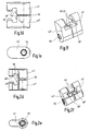
- the separation point 14 also has clamping means 44 for mutual clamping of the sub-elements 10,12, the two in the region of the cavity 38 in the first sub-element 10 radially guided clamping elements 44 ', 44 ", which are arranged opposite to each other with respect to the axis of rotation 16 and in the in Fig. 1b and c shown clamping position a wedge-shaped surfaces 48 ', 48 "which engage concentrically with the axis of rotation 16 of the tension bolt 36.
- the tensioning elements 44', 44" are in operative connection with common actuating means 50 which are adjustable between a release position and a tensioning position.
- the actuating means 50 are designed as differential screws, each having a in the two clamping elements 44 ', 44 "engaging, provided with opposite slopes threaded portion 52', 52". Stops 54 which limit the path of movement of the clamping elements 44 ', 44 "during the release process are also arranged in the first partial element 10. The stops 54 are formed by the head of a respective cap screw 56 engaging in the path of movement of the clamping elements 44', 44".
- a peculiarity of the invention is that the clamping elements 44 ', 44 "are provided with ejection portions 58, the release of the clamping elements from its clamping position by means of the differential screw 50 while exerting a force acting in the direction of ejection of the coupling member 22 axial force against the clamping elements facing effective surface 58 of the tension bolt 36.
- the tension bolt-side effective area is in both embodiments after Fig. 1a to c and Fig. 2a to c designed as an inner cone.
- Fig. 1a to c spherical roller bodies 62 are rotatably mounted in the area of the tension element-side ejection sections 60.
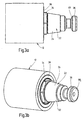
- Fig. 2a to c embodiment shown is intended for smaller diameter of the tool system.
- the slimmer design of the clamping elements allows the transverse dimension of the clamping elements 44 ', 44 "in the region of the differential screw 50 penetrating therethrough to be greater than in the region of the parts comprising the draw bolt 36 (cf. Fig. 2a and e ).
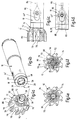
- a further special feature of the invention consists in the guidance of the coolant channels in the region of the separation point 14.
- Three variants for the coolant guide can be found in the groups of figures 4, 5 and 6. On the side of the first part element 10, the three variants match.
- the supply channel 64 which is arranged centrally on the supply side, is divided into four sub-channels 66 for bypassing the clamping elements 44 ', 44 ", which emerge from the second sub-element at a transition point in the region of the end face 20 via four openings 68.
- the three variants according to FIG Fig. 4 . 5 and 6 differ only in the channel guide on the side of the second sub-element.
- the transition point is formed in the region of the plane surface 26 by a circumferential groove 70, extend from the total of eight oblique supply channels 72 from their inlet openings 74 in the region of the groove 70 to their outlet openings 76 in the region of the flutes 78 in the direction of cutting 80.
- the Supply channels are arranged in the circumferential direction at a distance from each other and have the same course in the tool head.
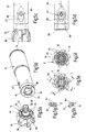
- inlet openings 84 are provided, which are congruent with the outlet openings 68 of the first partial element 10 and each open into two supply channels 72 within the second partial element 12 and from there to the outlet openings 86 in the region of the flutes 88 lead ,
- congruent inlet openings 94 are provided, which are guided via supply channels to central outlet openings 96 in the second sub-element 12 and there via a frontally inserted manifold 100 and there formed radial channels are led to the outside to the cutting 80.
- the distributor piece 100 which preferably consists of plastic, has a latching pin 102, with which it is inserted into an end-side mounting opening 104 of the second partial element 12 with a predetermined rotational orientation.
- the invention relates to a separation point 14 between two sub-elements 10,12 of a rotating around a rotation axis 16 tool system, in particular for use in machine tools.
- the separation point 14 comprises a first partial element 10 arranged, to the rotation axis 16 coaxial, at least partially conical receptacle 18 which is bounded by an annular end face 20.
- the second sub-element 12 carries a coupling part 22, which has a coupling pin 24 with a conical receiving surface 18 complementary conical surface 32 and an annular end face 20 facing, in a coupled state against this abutting annular plane surface 26.
- a tie bolt 36 axially over, which engages in a coupled state in a subsequent to the receptacle 18 cavity 38.
- the clamping elements are provided with ejection sections 60, which can be equipped with at least one rotating rolling element 62 mounted in a rotating manner.
Landscapes
- Engineering & Computer Science (AREA)
- Mechanical Engineering (AREA)
- General Engineering & Computer Science (AREA)
- Gripping On Spindles (AREA)
- Auxiliary Devices For Machine Tools (AREA)
- Machine Tool Units (AREA)
- Moulding By Coating Moulds (AREA)
- Details Of Spanners, Wrenches, And Screw Drivers And Accessories (AREA)
- Other Liquid Machine Or Engine Such As Wave Power Use (AREA)
- Lining Or Joining Of Plastics Or The Like (AREA)
- Earth Drilling (AREA)
- Perforating, Stamping-Out Or Severing By Means Other Than Cutting (AREA)
- Cutting Tools, Boring Holders, And Turrets (AREA)
- Moulds For Moulding Plastics Or The Like (AREA)
- Polishing Bodies And Polishing Tools (AREA)
- Making Paper Articles (AREA)
- Manipulator (AREA)
Priority Applications (1)
| Application Number | Priority Date | Filing Date | Title |
|---|---|---|---|
| PL07729731T PL2032295T3 (pl) | 2006-06-19 | 2007-05-31 | Miejsce podziału pomiędzy dwoma komponentami wirującego zespołu narzędziowego |
Applications Claiming Priority (2)
| Application Number | Priority Date | Filing Date | Title |
|---|---|---|---|
| DE102006028373.2A DE102006028373B4 (de) | 2006-06-19 | 2006-06-19 | Drehendes Werkzeugsystem mit einer Trennstelle zwischen zwei Teilelementen |
| PCT/EP2007/055328 WO2007147711A1 (de) | 2006-06-19 | 2007-05-31 | Trennstelle zwischen zwei teilelementen eines drehenden werkzeugsystems |
Publications (2)
| Publication Number | Publication Date |
|---|---|
| EP2032295A1 EP2032295A1 (de) | 2009-03-11 |
| EP2032295B1 true EP2032295B1 (de) | 2010-01-27 |
Family
ID=38372516
Family Applications (1)
| Application Number | Title | Priority Date | Filing Date |
|---|---|---|---|
| EP07729731A Active EP2032295B1 (de) | 2006-06-19 | 2007-05-31 | Trennstelle zwischen zwei teilelementen eines drehenden werkzeugsystems |
Country Status (10)
| Country | Link |
|---|---|
| US (2) | US8172490B2 (pl) |
| EP (1) | EP2032295B1 (pl) |
| JP (1) | JP5331684B2 (pl) |
| CN (1) | CN101360578B (pl) |
| AT (1) | ATE456412T1 (pl) |
| DE (3) | DE102006028373B4 (pl) |
| ES (1) | ES2338274T3 (pl) |
| IL (1) | IL191739A0 (pl) |
| PL (1) | PL2032295T3 (pl) |
| WO (1) | WO2007147711A1 (pl) |
Cited By (3)
| Publication number | Priority date | Publication date | Assignee | Title |
|---|---|---|---|---|
| EP2641679A2 (de) | 2012-03-23 | 2013-09-25 | Gühring OHG | Schnittstelle zwischen zwei Systemmodulen eines Werkzeugsystems |
| CN107740819A (zh) * | 2017-11-01 | 2018-02-27 | 镇江索达联轴器有限公司 | 一种锥形轴联轴器 |
| EP4427869A1 (en) * | 2023-03-07 | 2024-09-11 | Renishaw PLC | A machine tool accessory |
Families Citing this family (26)
| Publication number | Priority date | Publication date | Assignee | Title |
|---|---|---|---|---|
| US8033766B2 (en) * | 2008-05-09 | 2011-10-11 | Kennametal Inc. | Tool holder with ball clamping mechanism |
| US8257003B2 (en) * | 2008-12-05 | 2012-09-04 | Kennametal Inc. | Side actuated collet lock mechanism |
| US8998545B2 (en) * | 2009-01-16 | 2015-04-07 | John Wayne Stoneback | Retention knob for tool holder |
| DE102009012433A1 (de) * | 2009-03-10 | 2010-09-16 | Kennametal Inc. | Zerspanungswerkzeug für eine Werkzeugmaschine |
| DE102009042395A1 (de) * | 2009-09-16 | 2011-03-24 | Hartmetall-Werkzeugfabrik Paul Horn Gmbh | Reibwerkzeug zur spanenden Bearbeitung eines Werkstücks |
| EP2298483B1 (de) * | 2009-09-22 | 2015-09-16 | Gühring OHG | Reibahle und System zu Feinbearbeitung von Bohrungen mit einer solchen Reibahle und einem Einsatz |
| US20110135416A1 (en) * | 2009-12-04 | 2011-06-09 | Precision Drive Systems, LLC | Spindle apparatus for receiving and driving a tool holder |
| DE102010018254B4 (de) * | 2010-04-23 | 2022-11-10 | Kennametal Inc. | Kühlmittelverteiler |
| SE537368C2 (sv) * | 2011-04-29 | 2015-04-14 | Sandvik Intellectual Property | Fräsverktyg med ett tätande lock |
| WO2013180144A1 (ja) * | 2012-05-29 | 2013-12-05 | 株式会社タンガロイ | 連結装置および切削工具 |
| CN104767318B (zh) * | 2014-01-06 | 2017-05-03 | 和舰科技(苏州)有限公司 | 动力装置 |
| DE102014211420B3 (de) * | 2014-06-13 | 2015-11-05 | NUBIUS GROUP Präzisionswerkzeuge GmbH | Kupplung mit Ringkanal |
| DE102014211410B3 (de) * | 2014-06-13 | 2015-11-26 | NUBIUS GROUP Präzisionswerkzeuge GmbH | Werkzeugaufnahme mit Kühlmittelzufuhr über Ringkanal |
| DE102016105210A1 (de) * | 2016-03-21 | 2017-09-21 | Komet Group Gmbh | Spanabhebendes Werkzeug |
| EP3456446B1 (en) * | 2017-09-15 | 2025-11-05 | Sandvik Intellectual Property AB | Cutting tool part assembly |
| JP7053522B2 (ja) * | 2019-02-28 | 2022-04-12 | ファナック株式会社 | ロボットの固定装置、ロボットおよびロボットシステム |
| US11219987B2 (en) | 2019-06-06 | 2022-01-11 | George R Anex | Tool for installation and removal of retention knobs |
| EP3825045B1 (en) * | 2019-11-22 | 2022-08-10 | Seco Tools Ab | A cutting tool assembly |
| CN110883380B (zh) * | 2019-11-28 | 2021-01-29 | 株洲钻石切削刀具股份有限公司 | 一种复合切削刀具 |
| CN115397592B (zh) * | 2020-04-02 | 2025-03-14 | 山高刀具公司 | 具有相交以形成四边形面部部分的连续的主退屑槽和不连续的辅助退屑槽的旋转切削刀具 |
| DE102020120525A1 (de) * | 2020-08-04 | 2022-02-10 | Ott-Jakob Spanntechnik Gmbh | Werkzeug- oder Werkstückaufnahme |
| US20230321733A1 (en) * | 2020-08-21 | 2023-10-12 | Kyocera Corporation | Cutting insert, rotary tool, and method for manufacturing machined product |
| IT202100001679A1 (it) * | 2021-01-28 | 2022-07-28 | Officina Mecc Lombarda S R L | Dispositivo di bloccaggio per pezzi atti ad essere lavorati su macchine utensili |
| US12128484B2 (en) * | 2022-07-20 | 2024-10-29 | Kennametal Inc. | Cutting tool with modular pocket wall |
| CN115430853B (zh) * | 2022-10-28 | 2023-05-23 | 广东希普斯科技有限公司 | 一种内冷式多功能超高精密夹头 |
| CZ2024251A3 (cs) * | 2024-06-21 | 2025-09-03 | FINAL Tools a.s. | Sada vystružovacího nástroje, jeho upínací části a demontážního klíče a způsob demontáže |
Family Cites Families (23)
| Publication number | Priority date | Publication date | Assignee | Title |
|---|---|---|---|---|
| US2383688A (en) * | 1943-07-26 | 1945-08-28 | Tungsten Carbide Tool Company | Boring tool |
| US2485799A (en) * | 1946-08-07 | 1949-10-25 | Giddings & Lewis | Toolhead |
| US2684249A (en) * | 1950-11-30 | 1954-07-20 | Giddings & Lewis | Toolhead and taper shank adapter |
| US2893291A (en) * | 1956-07-20 | 1959-07-07 | Morey Machinery Co Inc | Draw toggles for spindle male tapers of milling and the like machines |
| US3341921A (en) * | 1966-01-10 | 1967-09-19 | Gen Electric | Cutting insert |
| JPS5419254A (en) * | 1977-07-14 | 1979-02-13 | Shirakawa Seisakushiyo Kk | Continuous dehumidifier |
| JPS5639845A (en) * | 1979-08-31 | 1981-04-15 | Hino Motors Ltd | Retainer for tool holder |
| SE427732B (sv) | 1979-09-20 | 1983-05-02 | Sandvik Ab | Verktygshallare |
| US4577875A (en) * | 1982-10-29 | 1986-03-25 | Miyakawa Industry Co., Ltd. | Exchange chuck for a tool |
| JPS58173446U (ja) * | 1983-03-28 | 1983-11-19 | 日野自動車株式会社 | 工具ホルダの保持装置 |
| US4575293A (en) * | 1984-07-12 | 1986-03-11 | Mario Berti | Machine tool holder having opposed ramp members |
| US4729702A (en) * | 1986-10-10 | 1988-03-08 | Carboloy Inc. | Clamping means for taper tool shanks |
| DE3711808A1 (de) * | 1987-04-08 | 1988-10-20 | Walter Gmbh Montanwerke | Mehrteiliges spannsystem, insbesondere fuer rundlaufende werkzeuge |
| US4829862A (en) * | 1987-08-17 | 1989-05-16 | Carboloy Inc. | Modular locking system |
| JP2681998B2 (ja) * | 1988-04-28 | 1997-11-26 | ブラザー工業株式会社 | 加工液供給装置 |
| KR890015820A (ko) * | 1988-04-28 | 1989-11-25 | 야스이 요시히로 | 가공액 공급장치 |
| US4919574A (en) * | 1989-03-31 | 1990-04-24 | Illinois Tool Works Inc. | Tool holder retention system |
| DE4019506A1 (de) | 1990-06-19 | 1992-01-02 | Fette Wilhelm Gmbh | Aufnahme mit einem dorn fuer spanabhebende maschinenwerkzeuge mit innenbohrung und maschinenwerkzeug |
| DE9006877U1 (de) * | 1990-06-19 | 1990-08-23 | Wilhelm Fette Gmbh, 2053 Schwarzenbek | Aufnahme mit einem Dorn für spanabhebende Maschinenwerkzeuge mit Innenbohrung und Maschinenwerkzeug |
| JPH0636706U (ja) * | 1992-10-20 | 1994-05-17 | 大昭和精機株式会社 | 工具ホルダー取付け装置 |
| DE29612743U1 (de) * | 1996-07-23 | 1997-11-27 | Eugen Fahrion GmbH & Co., 73667 Kaisersbach | Spannfutter |
| DE10048910A1 (de) * | 2000-10-02 | 2002-05-02 | Mapal Fab Praezision | Verbindungsstelle |
| CN2673563Y (zh) * | 2003-12-19 | 2005-01-26 | 萧如崧 | 主轴锁、退刀机构 |
-
2006
- 2006-06-19 DE DE102006028373.2A patent/DE102006028373B4/de not_active Expired - Fee Related
-
2007
- 2007-05-31 PL PL07729731T patent/PL2032295T3/pl unknown
- 2007-05-31 ES ES07729731T patent/ES2338274T3/es active Active
- 2007-05-31 WO PCT/EP2007/055328 patent/WO2007147711A1/de not_active Ceased
- 2007-05-31 EP EP07729731A patent/EP2032295B1/de active Active
- 2007-05-31 US US12/084,678 patent/US8172490B2/en active Active
- 2007-05-31 CN CN2007800017782A patent/CN101360578B/zh active Active
- 2007-05-31 AT AT07729731T patent/ATE456412T1/de active
- 2007-05-31 JP JP2009515808A patent/JP5331684B2/ja active Active
- 2007-05-31 DE DE502007002751T patent/DE502007002751D1/de active Active
- 2007-05-31 DE DE202007019172U patent/DE202007019172U1/de not_active Expired - Lifetime
-
2008
- 2008-05-27 IL IL191739A patent/IL191739A0/en active IP Right Grant
-
2012
- 2012-04-17 US US13/448,940 patent/US20120200050A1/en not_active Abandoned
Cited By (5)
| Publication number | Priority date | Publication date | Assignee | Title |
|---|---|---|---|---|
| EP2641679A2 (de) | 2012-03-23 | 2013-09-25 | Gühring OHG | Schnittstelle zwischen zwei Systemmodulen eines Werkzeugsystems |
| DE102012214923A1 (de) | 2012-03-23 | 2013-09-26 | Gühring Ohg | Schnittstelle zwischen zwei Systemmodulen eines Werkzeugsystems |
| CN107740819A (zh) * | 2017-11-01 | 2018-02-27 | 镇江索达联轴器有限公司 | 一种锥形轴联轴器 |
| EP4427869A1 (en) * | 2023-03-07 | 2024-09-11 | Renishaw PLC | A machine tool accessory |
| WO2024184616A1 (en) * | 2023-03-07 | 2024-09-12 | Renishaw Plc | A machine tool accessory |
Also Published As
| Publication number | Publication date |
|---|---|
| DE102006028373B4 (de) | 2016-01-21 |
| PL2032295T3 (pl) | 2010-07-30 |
| CN101360578B (zh) | 2010-12-08 |
| DE502007002751D1 (de) | 2010-03-18 |
| ATE456412T1 (de) | 2010-02-15 |
| US20090283975A1 (en) | 2009-11-19 |
| US20120200050A1 (en) | 2012-08-09 |
| DE202007019172U1 (de) | 2010-12-02 |
| JP2009541072A (ja) | 2009-11-26 |
| DE102006028373A1 (de) | 2007-12-20 |
| JP5331684B2 (ja) | 2013-10-30 |
| ES2338274T3 (es) | 2010-05-05 |
| IL191739A0 (en) | 2008-12-29 |
| US8172490B2 (en) | 2012-05-08 |
| EP2032295A1 (de) | 2009-03-11 |
| CN101360578A (zh) | 2009-02-04 |
| WO2007147711A1 (de) | 2007-12-27 |
Similar Documents
| Publication | Publication Date | Title |
|---|---|---|
| EP2032295B1 (de) | Trennstelle zwischen zwei teilelementen eines drehenden werkzeugsystems | |
| EP1474258B1 (de) | Maschinenreibahle | |
| EP0956920B2 (de) | Futter für drehantreibbare Werkzeuge, insbesondere Bohrer, Gewindebohrer o.dgl. | |
| DE3448086C2 (pl) | ||
| DE4032176C2 (de) | Scheibenschneider | |
| EP2300183A1 (de) | Ausbohrwerkzeug | |
| WO1990012193A1 (de) | Anschlusskupplung für bohrmaschine mit staubabsaugung | |
| DE69902907T2 (de) | Seitlich betätigte werkzeugeinspannvorrichtung | |
| DE69700028T2 (de) | Spannvorrichtung für Werkzeughalter mit Hohlkonus | |
| DE3004077C2 (de) | Bohrkrone | |
| DE10157450B4 (de) | Anordnung zur Einspeisung von Kühl- bzw. Schmiermittel in Werkzeuge | |
| DE102013104874B3 (de) | Werkzeugrevolver | |
| DE102012212677B4 (de) | Honwerkzeug, insbesondere zum Positionshonen | |
| DE19818148B4 (de) | Spannvorrichtung | |
| DE102009044995B4 (de) | Schneideinsatzträger, Schneideinsatzund drehangetriebenes Schneidwerkzeug | |
| DE102011005052A1 (de) | Spannsystem zur lösbaren Verbindung zweier vorzugsweise rotationssymetrischer Teile | |
| WO2000048776A1 (de) | Vorrichtung zum lösbaren verbinden eines werkzeugs mit einer maschinenspindel | |
| DD149621A5 (de) | Halter und mitnehmer fuer drehbare schneidwerkzeuge | |
| EP1660262B1 (de) | Schnittstelle eines werkzeugs | |
| DE102007057640B3 (de) | Werkzeugspanneinrichtung und Werkzeughalter | |
| WO2006136339A1 (de) | Schnittstelle eines werkzeugsystems | |
| DE202018006125U1 (de) | Werkzeug zur spanenden Bearbeitung eines Werkstücks | |
| EP2897751B1 (de) | Drehantreibbares spanabhebendes werkzeug | |
| EP3658321B1 (de) | Zerspanungswerkzeug | |
| EP1609550A1 (de) | Verbindungssystem und Werkzeugteil |
Legal Events
| Date | Code | Title | Description |
|---|---|---|---|
| PUAI | Public reference made under article 153(3) epc to a published international application that has entered the european phase |
Free format text: ORIGINAL CODE: 0009012 |
|
| 17P | Request for examination filed |
Effective date: 20080319 |
|
| AK | Designated contracting states |
Kind code of ref document: A1 Designated state(s): AT BE BG CH CY CZ DE DK EE ES FI FR GB GR HU IE IS IT LI LT LU LV MC MT NL PL PT RO SE SI SK TR |
|
| AX | Request for extension of the european patent |
Extension state: AL BA HR MK RS |
|
| 17Q | First examination report despatched |
Effective date: 20090505 |
|
| RAP1 | Party data changed (applicant data changed or rights of an application transferred) |
Owner name: KOMET GROUP GMBH |
|
| GRAP | Despatch of communication of intention to grant a patent |
Free format text: ORIGINAL CODE: EPIDOSNIGR1 |
|
| GRAS | Grant fee paid |
Free format text: ORIGINAL CODE: EPIDOSNIGR3 |
|
| GRAA | (expected) grant |
Free format text: ORIGINAL CODE: 0009210 |
|
| AK | Designated contracting states |
Kind code of ref document: B1 Designated state(s): AT BE BG CH CY CZ DE DK EE ES FI FR GB GR HU IE IS IT LI LT LU LV MC MT NL PL PT RO SE SI SK TR |
|
| REG | Reference to a national code |
Ref country code: GB Ref legal event code: FG4D Free format text: NOT ENGLISH |
|
| REG | Reference to a national code |
Ref country code: CH Ref legal event code: EP |
|
| REG | Reference to a national code |
Ref country code: IE Ref legal event code: FG4D |
|
| REF | Corresponds to: |
Ref document number: 502007002751 Country of ref document: DE Date of ref document: 20100318 Kind code of ref document: P |
|
| REG | Reference to a national code |
Ref country code: NL Ref legal event code: T3 |
|
| REG | Reference to a national code |
Ref country code: ES Ref legal event code: FG2A Ref document number: 2338274 Country of ref document: ES Kind code of ref document: T3 |
|
| REG | Reference to a national code |
Ref country code: SE Ref legal event code: TRGR |
|
| LTIE | Lt: invalidation of european patent or patent extension |
Effective date: 20100127 |
|
| PG25 | Lapsed in a contracting state [announced via postgrant information from national office to epo] |
Ref country code: PT Free format text: LAPSE BECAUSE OF FAILURE TO SUBMIT A TRANSLATION OF THE DESCRIPTION OR TO PAY THE FEE WITHIN THE PRESCRIBED TIME-LIMIT Effective date: 20100527 Ref country code: IS Free format text: LAPSE BECAUSE OF FAILURE TO SUBMIT A TRANSLATION OF THE DESCRIPTION OR TO PAY THE FEE WITHIN THE PRESCRIBED TIME-LIMIT Effective date: 20100527 Ref country code: LT Free format text: LAPSE BECAUSE OF FAILURE TO SUBMIT A TRANSLATION OF THE DESCRIPTION OR TO PAY THE FEE WITHIN THE PRESCRIBED TIME-LIMIT Effective date: 20100127 |
|
| REG | Reference to a national code |
Ref country code: PL Ref legal event code: T3 |
|
| REG | Reference to a national code |
Ref country code: IE Ref legal event code: FD4D |
|
| REG | Reference to a national code |
Ref country code: HU Ref legal event code: AG4A Ref document number: E007924 Country of ref document: HU |
|
| PG25 | Lapsed in a contracting state [announced via postgrant information from national office to epo] |
Ref country code: LV Free format text: LAPSE BECAUSE OF FAILURE TO SUBMIT A TRANSLATION OF THE DESCRIPTION OR TO PAY THE FEE WITHIN THE PRESCRIBED TIME-LIMIT Effective date: 20100127 Ref country code: SI Free format text: LAPSE BECAUSE OF FAILURE TO SUBMIT A TRANSLATION OF THE DESCRIPTION OR TO PAY THE FEE WITHIN THE PRESCRIBED TIME-LIMIT Effective date: 20100127 Ref country code: FI Free format text: LAPSE BECAUSE OF FAILURE TO SUBMIT A TRANSLATION OF THE DESCRIPTION OR TO PAY THE FEE WITHIN THE PRESCRIBED TIME-LIMIT Effective date: 20100127 |
|
| PG25 | Lapsed in a contracting state [announced via postgrant information from national office to epo] |
Ref country code: EE Free format text: LAPSE BECAUSE OF FAILURE TO SUBMIT A TRANSLATION OF THE DESCRIPTION OR TO PAY THE FEE WITHIN THE PRESCRIBED TIME-LIMIT Effective date: 20100127 Ref country code: GR Free format text: LAPSE BECAUSE OF FAILURE TO SUBMIT A TRANSLATION OF THE DESCRIPTION OR TO PAY THE FEE WITHIN THE PRESCRIBED TIME-LIMIT Effective date: 20100428 Ref country code: IE Free format text: LAPSE BECAUSE OF FAILURE TO SUBMIT A TRANSLATION OF THE DESCRIPTION OR TO PAY THE FEE WITHIN THE PRESCRIBED TIME-LIMIT Effective date: 20100127 Ref country code: RO Free format text: LAPSE BECAUSE OF FAILURE TO SUBMIT A TRANSLATION OF THE DESCRIPTION OR TO PAY THE FEE WITHIN THE PRESCRIBED TIME-LIMIT Effective date: 20100127 Ref country code: CY Free format text: LAPSE BECAUSE OF FAILURE TO SUBMIT A TRANSLATION OF THE DESCRIPTION OR TO PAY THE FEE WITHIN THE PRESCRIBED TIME-LIMIT Effective date: 20100127 |
|
| BERE | Be: lapsed |
Owner name: KOMET GROUP G.M.B.H. Effective date: 20100531 |
|
| PG25 | Lapsed in a contracting state [announced via postgrant information from national office to epo] |
Ref country code: SK Free format text: LAPSE BECAUSE OF FAILURE TO SUBMIT A TRANSLATION OF THE DESCRIPTION OR TO PAY THE FEE WITHIN THE PRESCRIBED TIME-LIMIT Effective date: 20100127 Ref country code: BG Free format text: LAPSE BECAUSE OF FAILURE TO SUBMIT A TRANSLATION OF THE DESCRIPTION OR TO PAY THE FEE WITHIN THE PRESCRIBED TIME-LIMIT Effective date: 20100427 |
|
| PLBE | No opposition filed within time limit |
Free format text: ORIGINAL CODE: 0009261 |
|
| STAA | Information on the status of an ep patent application or granted ep patent |
Free format text: STATUS: NO OPPOSITION FILED WITHIN TIME LIMIT |
|
| PG25 | Lapsed in a contracting state [announced via postgrant information from national office to epo] |
Ref country code: MC Free format text: LAPSE BECAUSE OF NON-PAYMENT OF DUE FEES Effective date: 20100531 |
|
| 26N | No opposition filed |
Effective date: 20101028 |
|
| PG25 | Lapsed in a contracting state [announced via postgrant information from national office to epo] |
Ref country code: DK Free format text: LAPSE BECAUSE OF FAILURE TO SUBMIT A TRANSLATION OF THE DESCRIPTION OR TO PAY THE FEE WITHIN THE PRESCRIBED TIME-LIMIT Effective date: 20100127 |
|
| PG25 | Lapsed in a contracting state [announced via postgrant information from national office to epo] |
Ref country code: IT Free format text: LAPSE BECAUSE OF NON-PAYMENT OF DUE FEES Effective date: 20100531 Ref country code: BE Free format text: LAPSE BECAUSE OF NON-PAYMENT OF DUE FEES Effective date: 20100531 |
|
| PG25 | Lapsed in a contracting state [announced via postgrant information from national office to epo] |
Ref country code: MT Free format text: LAPSE BECAUSE OF FAILURE TO SUBMIT A TRANSLATION OF THE DESCRIPTION OR TO PAY THE FEE WITHIN THE PRESCRIBED TIME-LIMIT Effective date: 20100127 |
|
| PGFP | Annual fee paid to national office [announced via postgrant information from national office to epo] |
Ref country code: HU Payment date: 20120529 Year of fee payment: 6 |
|
| PG25 | Lapsed in a contracting state [announced via postgrant information from national office to epo] |
Ref country code: LU Free format text: LAPSE BECAUSE OF NON-PAYMENT OF DUE FEES Effective date: 20100531 |
|
| PG25 | Lapsed in a contracting state [announced via postgrant information from national office to epo] |
Ref country code: TR Free format text: LAPSE BECAUSE OF FAILURE TO SUBMIT A TRANSLATION OF THE DESCRIPTION OR TO PAY THE FEE WITHIN THE PRESCRIBED TIME-LIMIT Effective date: 20100127 |
|
| PGFP | Annual fee paid to national office [announced via postgrant information from national office to epo] |
Ref country code: NL Payment date: 20130523 Year of fee payment: 7 |
|
| PG25 | Lapsed in a contracting state [announced via postgrant information from national office to epo] |
Ref country code: HU Free format text: LAPSE BECAUSE OF NON-PAYMENT OF DUE FEES Effective date: 20130601 |
|
| REG | Reference to a national code |
Ref country code: NL Ref legal event code: V1 Effective date: 20141201 |
|
| PG25 | Lapsed in a contracting state [announced via postgrant information from national office to epo] |
Ref country code: NL Free format text: LAPSE BECAUSE OF NON-PAYMENT OF DUE FEES Effective date: 20141201 |
|
| REG | Reference to a national code |
Ref country code: FR Ref legal event code: PLFP Year of fee payment: 10 |
|
| REG | Reference to a national code |
Ref country code: FR Ref legal event code: PLFP Year of fee payment: 11 |
|
| REG | Reference to a national code |
Ref country code: FR Ref legal event code: PLFP Year of fee payment: 12 |
|
| PGFP | Annual fee paid to national office [announced via postgrant information from national office to epo] |
Ref country code: PL Payment date: 20250523 Year of fee payment: 19 Ref country code: DE Payment date: 20250521 Year of fee payment: 19 |
|
| PGFP | Annual fee paid to national office [announced via postgrant information from national office to epo] |
Ref country code: GB Payment date: 20250521 Year of fee payment: 19 Ref country code: ES Payment date: 20250627 Year of fee payment: 19 |
|
| PGFP | Annual fee paid to national office [announced via postgrant information from national office to epo] |
Ref country code: IT Payment date: 20250527 Year of fee payment: 19 |
|
| PGFP | Annual fee paid to national office [announced via postgrant information from national office to epo] |
Ref country code: FR Payment date: 20250528 Year of fee payment: 19 |
|
| PGFP | Annual fee paid to national office [announced via postgrant information from national office to epo] |
Ref country code: CH Payment date: 20250601 Year of fee payment: 19 |
|
| PGFP | Annual fee paid to national office [announced via postgrant information from national office to epo] |
Ref country code: AT Payment date: 20250522 Year of fee payment: 19 |
|
| PGFP | Annual fee paid to national office [announced via postgrant information from national office to epo] |
Ref country code: CZ Payment date: 20250522 Year of fee payment: 19 |
|
| PGFP | Annual fee paid to national office [announced via postgrant information from national office to epo] |
Ref country code: SE Payment date: 20250521 Year of fee payment: 19 |