EP2032295B1 - Junction between two components of a rotating tool system - Google Patents
Junction between two components of a rotating tool system Download PDFInfo
- Publication number
- EP2032295B1 EP2032295B1 EP07729731A EP07729731A EP2032295B1 EP 2032295 B1 EP2032295 B1 EP 2032295B1 EP 07729731 A EP07729731 A EP 07729731A EP 07729731 A EP07729731 A EP 07729731A EP 2032295 B1 EP2032295 B1 EP 2032295B1
- Authority
- EP
- European Patent Office
- Prior art keywords
- sub
- tool system
- rotary tool
- elements
- clamping
- Prior art date
- Legal status (The legal status is an assumption and is not a legal conclusion. Google has not performed a legal analysis and makes no representation as to the accuracy of the status listed.)
- Active
Links
Images


Classifications
-
- B—PERFORMING OPERATIONS; TRANSPORTING
- B23—MACHINE TOOLS; METAL-WORKING NOT OTHERWISE PROVIDED FOR
- B23B—TURNING; BORING
- B23B31/00—Chucks; Expansion mandrels; Adaptations thereof for remote control
- B23B31/02—Chucks
- B23B31/10—Chucks characterised by the retaining or gripping devices or their immediate operating means
- B23B31/107—Retention by laterally-acting detents, e.g. pins, screws, wedges; Retention by loose elements, e.g. balls
- B23B31/1075—Retention by screws
- B23B31/1077—Retention by screws acting on a floating pin
-
- B—PERFORMING OPERATIONS; TRANSPORTING
- B23—MACHINE TOOLS; METAL-WORKING NOT OTHERWISE PROVIDED FOR
- B23B—TURNING; BORING
- B23B31/00—Chucks; Expansion mandrels; Adaptations thereof for remote control
- B23B31/02—Chucks
- B23B31/06—Features relating to the removal of tools; Accessories therefor
-
- B—PERFORMING OPERATIONS; TRANSPORTING
- B23—MACHINE TOOLS; METAL-WORKING NOT OTHERWISE PROVIDED FOR
- B23D—PLANING; SLOTTING; SHEARING; BROACHING; SAWING; FILING; SCRAPING; LIKE OPERATIONS FOR WORKING METAL BY REMOVING MATERIAL, NOT OTHERWISE PROVIDED FOR
- B23D77/00—Reaming tools
- B23D77/006—Reaming tools with means for lubricating or cooling
-
- F—MECHANICAL ENGINEERING; LIGHTING; HEATING; WEAPONS; BLASTING
- F16—ENGINEERING ELEMENTS AND UNITS; GENERAL MEASURES FOR PRODUCING AND MAINTAINING EFFECTIVE FUNCTIONING OF MACHINES OR INSTALLATIONS; THERMAL INSULATION IN GENERAL
- F16D—COUPLINGS FOR TRANSMITTING ROTATION; CLUTCHES; BRAKES
- F16D1/00—Couplings for rigidly connecting two coaxial shafts or other movable machine elements
- F16D1/06—Couplings for rigidly connecting two coaxial shafts or other movable machine elements for attachment of a member on a shaft or on a shaft-end
- F16D1/08—Couplings for rigidly connecting two coaxial shafts or other movable machine elements for attachment of a member on a shaft or on a shaft-end with clamping hub; with hub and longitudinal key
- F16D1/09—Couplings for rigidly connecting two coaxial shafts or other movable machine elements for attachment of a member on a shaft or on a shaft-end with clamping hub; with hub and longitudinal key with radial clamping due to axial loading of at least one pair of conical surfaces
- F16D1/092—Couplings for rigidly connecting two coaxial shafts or other movable machine elements for attachment of a member on a shaft or on a shaft-end with clamping hub; with hub and longitudinal key with radial clamping due to axial loading of at least one pair of conical surfaces the pair of conical mating surfaces being provided on the coupled hub and shaft
-
- B—PERFORMING OPERATIONS; TRANSPORTING
- B23—MACHINE TOOLS; METAL-WORKING NOT OTHERWISE PROVIDED FOR
- B23B—TURNING; BORING
- B23B2231/00—Details of chucks, toolholder shanks or tool shanks
- B23B2231/02—Features of shanks of tools not relating to the operation performed by the tool
- B23B2231/0204—Connection of shanks to working elements of tools
-
- B—PERFORMING OPERATIONS; TRANSPORTING
- B23—MACHINE TOOLS; METAL-WORKING NOT OTHERWISE PROVIDED FOR
- B23B—TURNING; BORING
- B23B2231/00—Details of chucks, toolholder shanks or tool shanks
- B23B2231/24—Cooling or lubrication means
-
- B—PERFORMING OPERATIONS; TRANSPORTING
- B23—MACHINE TOOLS; METAL-WORKING NOT OTHERWISE PROVIDED FOR
- B23B—TURNING; BORING
- B23B2265/00—Details of general geometric configurations
- B23B2265/32—Polygonal
-
- B—PERFORMING OPERATIONS; TRANSPORTING
- B23—MACHINE TOOLS; METAL-WORKING NOT OTHERWISE PROVIDED FOR
- B23D—PLANING; SLOTTING; SHEARING; BROACHING; SAWING; FILING; SCRAPING; LIKE OPERATIONS FOR WORKING METAL BY REMOVING MATERIAL, NOT OTHERWISE PROVIDED FOR
- B23D2277/00—Reaming tools
- B23D2277/02—Cutting head and shank made from two different components which are releasably or non-releasably attached to each other
-
- Y—GENERAL TAGGING OF NEW TECHNOLOGICAL DEVELOPMENTS; GENERAL TAGGING OF CROSS-SECTIONAL TECHNOLOGIES SPANNING OVER SEVERAL SECTIONS OF THE IPC; TECHNICAL SUBJECTS COVERED BY FORMER USPC CROSS-REFERENCE ART COLLECTIONS [XRACs] AND DIGESTS
- Y10—TECHNICAL SUBJECTS COVERED BY FORMER USPC
- Y10T—TECHNICAL SUBJECTS COVERED BY FORMER US CLASSIFICATION
- Y10T279/00—Chucks or sockets
- Y10T279/17—Socket type
- Y10T279/17666—Radially reciprocating jaws
- Y10T279/17675—Transverse-screw actuated
-
- Y—GENERAL TAGGING OF NEW TECHNOLOGICAL DEVELOPMENTS; GENERAL TAGGING OF CROSS-SECTIONAL TECHNOLOGIES SPANNING OVER SEVERAL SECTIONS OF THE IPC; TECHNICAL SUBJECTS COVERED BY FORMER USPC CROSS-REFERENCE ART COLLECTIONS [XRACs] AND DIGESTS
- Y10—TECHNICAL SUBJECTS COVERED BY FORMER USPC
- Y10T—TECHNICAL SUBJECTS COVERED BY FORMER US CLASSIFICATION
- Y10T279/00—Chucks or sockets
- Y10T279/17—Socket type
- Y10T279/17761—Side detent
-
- Y—GENERAL TAGGING OF NEW TECHNOLOGICAL DEVELOPMENTS; GENERAL TAGGING OF CROSS-SECTIONAL TECHNOLOGIES SPANNING OVER SEVERAL SECTIONS OF THE IPC; TECHNICAL SUBJECTS COVERED BY FORMER USPC CROSS-REFERENCE ART COLLECTIONS [XRACs] AND DIGESTS
- Y10—TECHNICAL SUBJECTS COVERED BY FORMER USPC
- Y10T—TECHNICAL SUBJECTS COVERED BY FORMER US CLASSIFICATION
- Y10T408/00—Cutting by use of rotating axially moving tool
- Y10T408/44—Cutting by use of rotating axially moving tool with means to apply transient, fluent medium to work or product
- Y10T408/45—Cutting by use of rotating axially moving tool with means to apply transient, fluent medium to work or product including Tool with duct
-
- Y—GENERAL TAGGING OF NEW TECHNOLOGICAL DEVELOPMENTS; GENERAL TAGGING OF CROSS-SECTIONAL TECHNOLOGIES SPANNING OVER SEVERAL SECTIONS OF THE IPC; TECHNICAL SUBJECTS COVERED BY FORMER USPC CROSS-REFERENCE ART COLLECTIONS [XRACs] AND DIGESTS
- Y10—TECHNICAL SUBJECTS COVERED BY FORMER USPC
- Y10T—TECHNICAL SUBJECTS COVERED BY FORMER US CLASSIFICATION
- Y10T408/00—Cutting by use of rotating axially moving tool
- Y10T408/94—Tool-support
- Y10T408/95—Tool-support with tool-retaining means
- Y10T408/953—Clamping jaws
-
- Y—GENERAL TAGGING OF NEW TECHNOLOGICAL DEVELOPMENTS; GENERAL TAGGING OF CROSS-SECTIONAL TECHNOLOGIES SPANNING OVER SEVERAL SECTIONS OF THE IPC; TECHNICAL SUBJECTS COVERED BY FORMER USPC CROSS-REFERENCE ART COLLECTIONS [XRACs] AND DIGESTS
- Y10—TECHNICAL SUBJECTS COVERED BY FORMER USPC
- Y10T—TECHNICAL SUBJECTS COVERED BY FORMER US CLASSIFICATION
- Y10T409/00—Gear cutting, milling, or planing
- Y10T409/30—Milling
- Y10T409/309352—Cutter spindle or spindle support
- Y10T409/309408—Cutter spindle or spindle support with cutter holder
-
- Y—GENERAL TAGGING OF NEW TECHNOLOGICAL DEVELOPMENTS; GENERAL TAGGING OF CROSS-SECTIONAL TECHNOLOGIES SPANNING OVER SEVERAL SECTIONS OF THE IPC; TECHNICAL SUBJECTS COVERED BY FORMER USPC CROSS-REFERENCE ART COLLECTIONS [XRACs] AND DIGESTS
- Y10—TECHNICAL SUBJECTS COVERED BY FORMER USPC
- Y10T—TECHNICAL SUBJECTS COVERED BY FORMER US CLASSIFICATION
- Y10T409/00—Gear cutting, milling, or planing
- Y10T409/30—Milling
- Y10T409/30952—Milling with cutter holder
Definitions
- the invention relates to a rotating about an axis of rotation tool system with a separation point between two sub-elements for use in machine tools, arranged with a arranged on a first sub-element, coaxial with the axis of rotation, at least partially conical recording, which is bounded by an annular end face, with a arranged on a second sub-element coupling portion having a coupling pin with a conical receiving complementary conical surface and a ring-shaped end face facing in coupled state against this annular planar surface, with a over the free end of the coupling pin axially projecting tie bolt, in the coupled state engages in a cavity adjoining the receptacle, and with operable from the outside clamping means for mutual clamping of the sub-elements, which have two radially guided in the first sub-element clamping elements, the beob Lich of the axis of rotation are arranged opposite and wear in a clamping position concentric to the axis of rotation Konuspartie the tie bolt under wedge
- Rotating tool systems with separation points of this type are known ( DE-C-37 11 808 ). Their advantage is that despite the provided for the tension of the sub-elements axially aligned tension bolt radial actuation is possible. However, it has been shown that due to the combined Cone and planar clamping a release of the sub-elements in the region of the separation point only with a certain amount of force is possible.
- the invention is therefore based on the object to improve the known separation point of the type specified in that with the common actuating means a radial and yet radial force-free clamping and solution of the sub-elements is possible.
- the solution according to the invention is based primarily on the idea that the clamping elements are provided with additional ejection parts, which strike upon release of the actuating means from the clamping position while exerting an axial force acting in the direction of ejection of the coupling part against one of the clamping elements facing effective surface of the tie bolt, the zugbolzen workede Active surface and / or the tensioning element side ejection may be equipped with at least one rotating rolling elements.
- the rolling elements ensure that the transmission of force can be largely friction-free and therefore free of radial force during the ejection process.
- the rolling elements may be spherical, barrel-shaped or cylindrical.
- a preferred embodiment of the invention provides that the tension bolt-side effective surface forms an inner cone and that the clamping elements have a during the release process against the inner cone abutting, radially als noteworthyde with this rolling elements ejection.
- the ejection parts can be formed in the form of a respective projection, an inclined surface on the clamping elements or formed by the rolling elements.
- a further improvement of the radial force-free power transmission during clamping and releasing operation is achieved in that the clamping elements are guided floating in a radial guide of the body.
- the actuating means are expediently designed as a differential screw, each having a engaging in the two clamping elements, provided with opposite slopes threaded portion.
- stops are arranged in the first part element, which limit the movement path of the clamping elements during the release process. The attacks can be formed by engaging with her head in the path of movement of the clamping elements head screws.
- a further preferred embodiment of the invention provides that in an intermediate region between the end face or the plane surface on the one hand and the conical receiving or pin surface on the other hand depending on a rotational engagement portion is arranged, which may be formed as mutually complementary polygonal surfaces.
- a further preferred embodiment of the invention provides that formed as a differential screw actuating means outside of the tension bolt receiving part penetrates the clamping elements and that the transverse dimension of the clamping elements in the region of the actuating means is greater than in the region comprising the tension bolt parts.
- the sub-elements communicate with each other cooling channels, wherein in the first sub-element at least one around the clamping elements around to a transition point guided inlet channel and in the second sub-element at least one connected to the junction supply channel is arranged for a plurality of cutting elements.
- the transition point may be formed as an annular channel communicating with the at least one inlet channel and the at least one supply channel.
- the annular channel can be limited by a circumferential groove in one of the sub-elements as well as by a groove over the cross-sectional area in the other sub-element.
- the transition point is formed by congruent transition openings in the two subelements, wherein the supply channels branched off from the transition openings can emerge in the second subelement in the region of cutting elements.
- a distributor piece engaging in the supply channel which contains distribution grooves leading to the individual cutting elements and communicating with the supply channel.
- the distributor piece can have a plug-in pin rotationally oriented in the second sub-element.
- the invention further relates to a rotary tool system for use in machine tools, which consists of two sub-elements, which are interconnected at a separation point of the type described above.
- the first sub-element can be designed as a machine spindle, adapter piece or tool holder, while the second sub-element is expediently designed as a tool head.
- the tool systems shown in the drawing are concentricity tools for use in machine tools, which are exemplary are designed as reaming tools.
- the tool systems consist essentially of a first sub-element 10, which is formed in the embodiment shown as a tool holder or machine spindle, a second sub-element 12, which is exemplified as a tool head.
- the two sub-elements 10,12 are detachably connected together at a separation point 14. In addition, takes place at the separation point 14, a coolant transfer from the first to the second sub-element 10,12.
- the separating point 14 has a receptacle 18 which is arranged coaxially with the axis of rotation 16 of the tool system and which is arranged on the first part element 10 and is bounded on the outside by an annular end face 20.
- the separating point 14 further includes the coupling part 22 arranged on the second part element 12, which has a coupling pin 24 and an annular end face 26 in the coupled state against the annular end face 20 of the first part element 10.
- the receptacle 18 has in its interior a conical receiving portion 28 and arranged between the conical receiving portion 28 and the end face 20 formed as a polygonal surface rotational engagement portion 30, while the coupling pin complementary to the conical receiving portion 28 conical surface 32 and between the conical surface 32 and the Plane surface 26 arranged, complementary to the rotational engagement portion 30, polygonal Drehit philosophicalpartie 34 has.
- a tie bolt 36 axially over and engages in the assembled state in a subsequent to the receptacle 18 cavity 38 of the first sub-element.
- the tension bolt 36 is screwed with an axially projecting threaded shaft 40 in a threaded bore 42 of the second part element and fixed there rigid.
- the separation point 14 also has clamping means 44 for mutual clamping of the sub-elements 10,12, the two in the region of the cavity 38 in the first sub-element 10 radially guided clamping elements 44 ', 44 ", which are arranged opposite to each other with respect to the axis of rotation 16 and in the in Fig. 1b and c shown clamping position a wedge-shaped surfaces 48 ', 48 "which engage concentrically with the axis of rotation 16 of the tension bolt 36.
- the tensioning elements 44', 44" are in operative connection with common actuating means 50 which are adjustable between a release position and a tensioning position.
- the actuating means 50 are designed as differential screws, each having a in the two clamping elements 44 ', 44 "engaging, provided with opposite slopes threaded portion 52', 52". Stops 54 which limit the path of movement of the clamping elements 44 ', 44 "during the release process are also arranged in the first partial element 10. The stops 54 are formed by the head of a respective cap screw 56 engaging in the path of movement of the clamping elements 44', 44".
- a peculiarity of the invention is that the clamping elements 44 ', 44 "are provided with ejection portions 58, the release of the clamping elements from its clamping position by means of the differential screw 50 while exerting a force acting in the direction of ejection of the coupling member 22 axial force against the clamping elements facing effective surface 58 of the tension bolt 36.
- the tension bolt-side effective area is in both embodiments after Fig. 1a to c and Fig. 2a to c designed as an inner cone.
- Fig. 1a to c spherical roller bodies 62 are rotatably mounted in the area of the tension element-side ejection sections 60.
- Fig. 2a to c embodiment shown is intended for smaller diameter of the tool system.
- the slimmer design of the clamping elements allows the transverse dimension of the clamping elements 44 ', 44 "in the region of the differential screw 50 penetrating therethrough to be greater than in the region of the parts comprising the draw bolt 36 (cf. Fig. 2a and e ).
- a further special feature of the invention consists in the guidance of the coolant channels in the region of the separation point 14.
- Three variants for the coolant guide can be found in the groups of figures 4, 5 and 6. On the side of the first part element 10, the three variants match.
- the supply channel 64 which is arranged centrally on the supply side, is divided into four sub-channels 66 for bypassing the clamping elements 44 ', 44 ", which emerge from the second sub-element at a transition point in the region of the end face 20 via four openings 68.
- the three variants according to FIG Fig. 4 . 5 and 6 differ only in the channel guide on the side of the second sub-element.
- the transition point is formed in the region of the plane surface 26 by a circumferential groove 70, extend from the total of eight oblique supply channels 72 from their inlet openings 74 in the region of the groove 70 to their outlet openings 76 in the region of the flutes 78 in the direction of cutting 80.
- the Supply channels are arranged in the circumferential direction at a distance from each other and have the same course in the tool head.
- inlet openings 84 are provided, which are congruent with the outlet openings 68 of the first partial element 10 and each open into two supply channels 72 within the second partial element 12 and from there to the outlet openings 86 in the region of the flutes 88 lead ,
- congruent inlet openings 94 are provided, which are guided via supply channels to central outlet openings 96 in the second sub-element 12 and there via a frontally inserted manifold 100 and there formed radial channels are led to the outside to the cutting 80.
- the distributor piece 100 which preferably consists of plastic, has a latching pin 102, with which it is inserted into an end-side mounting opening 104 of the second partial element 12 with a predetermined rotational orientation.
- the invention relates to a separation point 14 between two sub-elements 10,12 of a rotating around a rotation axis 16 tool system, in particular for use in machine tools.
- the separation point 14 comprises a first partial element 10 arranged, to the rotation axis 16 coaxial, at least partially conical receptacle 18 which is bounded by an annular end face 20.
- the second sub-element 12 carries a coupling part 22, which has a coupling pin 24 with a conical receiving surface 18 complementary conical surface 32 and an annular end face 20 facing, in a coupled state against this abutting annular plane surface 26.
- a tie bolt 36 axially over, which engages in a coupled state in a subsequent to the receptacle 18 cavity 38.
- the clamping elements are provided with ejection sections 60, which can be equipped with at least one rotating rolling element 62 mounted in a rotating manner.
Abstract
Description
Die Erfindung bezieht sich auf ein um eine Drehachse drehendes Werkzeugsystem mit einer Trennstelle zwischen zwei Teilelementen für den Einsatz in Werkzeugmaschinen, mit einer an einem ersten Teilelement angeordneten, zur Drehachse koaxialen, zumindest partiell konischen Aufnahme, die von einer ringförmigen Stirnfläche begrenzt ist, mit einer an einem zweiten Teilelement angeordneten Kupplungspartie, die einen Kupplungszapfen mit einer zur konischen Aufnahme komplementäre Kegelfläche und eine zur ringförmigen Stirnfläche weisende, in gekuppeltem Zustand gegen diese anliegende ringförmige Planfläche aufweist, mit einem über das freie Ende des Kupplungszapfens axial überstehenden Zugbolzen, der in gekuppeltem Zustand in einen sich an die Aufnahme anschließenden Hohlraum eingreift, und mit von der Außenseite her betätigbaren Spannmitteln zum gegenseitigen Verspannen der Teilelemente, die zwei im ersten Teilelement radial geführte Spannelemente aufweisen, die einander bezüglich der Drehachse gegenüberliegend angeordnet sind und in einer Spannstellung eine zur Drehachse konzentrische Konuspartie des Zugbolzens untergreifende Keilflächen tragen, und die in Wirkverbindung mit gemeinsamen Betätigungsmitteln stehen, durch die sie zwischen einer Lösestellung und einer Spannstellung verstellbar sind. Als erstes Teilelement mit einer Aufnahme kommen dabei insbesondere Werkzeugspindeln, Werkzeugadapter oder auch Werkzeughalter in Betracht, während als zweite Teilelemente vor allem Werkzeugköpfe, Werkzeughalter oder Schneidenträger in Betracht kommen.The invention relates to a rotating about an axis of rotation tool system with a separation point between two sub-elements for use in machine tools, arranged with a arranged on a first sub-element, coaxial with the axis of rotation, at least partially conical recording, which is bounded by an annular end face, with a arranged on a second sub-element coupling portion having a coupling pin with a conical receiving complementary conical surface and a ring-shaped end face facing in coupled state against this annular planar surface, with a over the free end of the coupling pin axially projecting tie bolt, in the coupled state engages in a cavity adjoining the receptacle, and with operable from the outside clamping means for mutual clamping of the sub-elements, which have two radially guided in the first sub-element clamping elements, the beob Lich of the axis of rotation are arranged opposite and wear in a clamping position concentric to the axis of rotation Konuspartie the tie bolt under wedge surfaces, and are in operative connection with common actuating means, by which they are adjustable between a release position and a clamping position. In particular, tool spindles, tool adapters or even tool holders come into consideration as the first subelement with a receptacle, while, as the second subelements, especially tool heads, tool holders or blade carriers come into consideration.
Drehende Werkzeugsysteme mit Trennstellen dieser Art sind bekannt (
Der Erfindung liegt daher die Aufgabe zugrunde, die bekannte Trennstelle der eingangs angegebenen Art dahingehend zu verbessern, dass mit den gemeinsamen Betätigungsmitteln eine radiale und dennoch radialkraftfreie Einspannung und Lösung der Teilelemente möglich ist.The invention is therefore based on the object to improve the known separation point of the type specified in that with the common actuating means a radial and yet radial force-free clamping and solution of the sub-elements is possible.
Zur Lösung dieser Aufgabe wird die in dem Patentanspruch 1 angegebene Merkmalskombination vorgeschlagen. Vorteilhafte Ausgestaltungen und Weiterbildungen der Erfindung ergeben sich aus den abhängigen Ansprüchen.To solve this problem, the combination of features specified in
Die erfindungsgemäße Lösung geht vor allem von dem Gedanken aus, dass die Spannelemente mit zusätzlichen Auswurfpartien versehen sind, die beim Lösen des Betätigungsmittels aus der Spannstellung unter Ausübung einer in Auswurfrichtung des Kupplungsteils wirkenden Axialkraft gegen eine des Spannelemente zugewandte Wirkfläche des Zugbolzens anschlagen, wobei die zugbolzenseitige Wirkfläche und/oder die spannelementseitigen Auswurfpartien mit mindestens einem drehend gelagerten Wälzkörper bestückt sein kann. Die Wälzkörper sorgen dafür, dass die Kraftübertragung auch beim Auswurfvorgang weitgehend reibungsfrei und damit radialkraftfrei erfolgen kann. Die Wälzkörper können kugelförmig, tonnenförmig oder zylindrisch ausgebildet sein.The solution according to the invention is based primarily on the idea that the clamping elements are provided with additional ejection parts, which strike upon release of the actuating means from the clamping position while exerting an axial force acting in the direction of ejection of the coupling part against one of the clamping elements facing effective surface of the tie bolt, the zugbolzenseitige Active surface and / or the tensioning element side ejection may be equipped with at least one rotating rolling elements. The rolling elements ensure that the transmission of force can be largely friction-free and therefore free of radial force during the ejection process. The rolling elements may be spherical, barrel-shaped or cylindrical.
Eine bevorzugte Ausgestaltung der Erfindung sieht vor, dass die zugbolzenseitige Wirkfläche einen Innenkonus bildet und dass die Spannelemente eine beim Lösevorgang gegen den Innenkonus anschlagende, auf diesem mit den Wälzelementen radial auflaufende Auswurfpartie aufweisen. Die Auswurfpartien können in Form je eines Vorsprungs, einer Schrägfläche an den Spannelementen angeformt oder durch die Wälzelemente gebildet sein.A preferred embodiment of the invention provides that the tension bolt-side effective surface forms an inner cone and that the clamping elements have a during the release process against the inner cone abutting, radially auflaufende with this rolling elements ejection. The ejection parts can be formed in the form of a respective projection, an inclined surface on the clamping elements or formed by the rolling elements.
Eine weitere Verbesserung der radialkraftfreien Kraftübertragung beim Spann- und Lösevorgang wird dadurch erzielt, dass die Spannelemente in einer Radialführung des Grundkörpers schwimmend geführt sind. Die Betätigungsmittel sind dabei zweckmäßig als Differentialschraube ausgebildet, die je einen in die beiden Spannelemente eingreifenden, mit gegenläufigen Steigungen versehenen Gewindeabschnitt aufweisen. Vorteilhafterweise sind im ersten Teilelement Anschläge angeordnet, die den Bewegungsweg der Spannelemente beim Lösevorgang begrenzen. Die Anschläge können dabei durch mit ihrem Kopf in den Bewegungsweg der Spannelemente eingreifende Kopfschrauben ausgebildet sein.A further improvement of the radial force-free power transmission during clamping and releasing operation is achieved in that the clamping elements are guided floating in a radial guide of the body. The actuating means are expediently designed as a differential screw, each having a engaging in the two clamping elements, provided with opposite slopes threaded portion. Advantageously, stops are arranged in the first part element, which limit the movement path of the clamping elements during the release process. The attacks can be formed by engaging with her head in the path of movement of the clamping elements head screws.
Eine weitere bevorzugte Ausgestaltung der Erfindung sieht vor, dass in einem Zwischenbereich zwischen der Stirnfläche bzw. der Planfläche einerseits und der konischen Aufnahme- oder Zapfenfläche andererseits je eine Drehmitnahmepartie angeordnet ist, die als zueinander komplementäre Mehrkantflächen ausgebildet sein können.A further preferred embodiment of the invention provides that in an intermediate region between the end face or the plane surface on the one hand and the conical receiving or pin surface on the other hand depending on a rotational engagement portion is arranged, which may be formed as mutually complementary polygonal surfaces.
Eine weitere bevorzugte Ausgestaltung der Erfindung sieht vor, dass die als Differentialschraube ausgebildeten Betätigungsmittel außerhalb des den Zugbolzen aufnehmenden Teils die Spannelemente durchdringt und dass die Querabmessung der Spannelemente im Bereich der Betätigungsmittel größer als im Bereich der den Zugbolzen umfassenden Teile ist.A further preferred embodiment of the invention provides that formed as a differential screw actuating means outside of the tension bolt receiving part penetrates the clamping elements and that the transverse dimension of the clamping elements in the region of the actuating means is greater than in the region comprising the tension bolt parts.
Gemäß einer vorteilhaften Ausgestaltung der Erfindung weisen die Teilelemente miteinander kommunizierende Kühlkanäle auf, wobei im ersten Teilelement mindestens ein um die Spannelemente herum zu einer Übergangsstelle geführter Zulaufkanal und im zweiten Teilelement mindestens ein an die Übergangsstelle angeschlossener Versorgungskanal für eine Mehrzahl von Schneidelementen angeordnet ist. Dabei kann nach einer ersten Ausführungsvariante die Übergangsstelle als mit dem mindestens einen Zulaufkanal und dem mindestens einen Versorgungskanal kommunizierender Ringkanal ausgebildet sein. Der Ringkanal kann dabei durch eine umlaufende Nut in einem der Teilelemente sowie durch eine die Nut übergreifende Trennfläche im anderen Teilelement begrenzt sein. Gemäß einer zweiten Ausführungsvariante ist die Übergangsstelle durch deckungsgleiche Übergangsöffnungen in den beiden Teilelementen gebildet, wobei die von den Übergangsöffnungen abgezweigten Versorgungskanäle im zweiten Teilelement im Bereich von Schneidelementen austreten können.According to an advantageous embodiment of the invention, the sub-elements communicate with each other cooling channels, wherein in the first sub-element at least one around the clamping elements around to a transition point guided inlet channel and in the second sub-element at least one connected to the junction supply channel is arranged for a plurality of cutting elements. In this case, according to a first embodiment, the transition point may be formed as an annular channel communicating with the at least one inlet channel and the at least one supply channel. The annular channel can be limited by a circumferential groove in one of the sub-elements as well as by a groove over the cross-sectional area in the other sub-element. According to a second embodiment variant, the transition point is formed by congruent transition openings in the two subelements, wherein the supply channels branched off from the transition openings can emerge in the second subelement in the region of cutting elements.
Gemäß einer dritten Ausführungsvariante ist ein in den Versorgungskanal eingreifendes Verteilerstück vorgesehen, das zu den einzelnen Schneidelementen führende, mit dem Versorgungskanal kommunizierende Verteilernuten enthält. Das Verteilerstück kann dabei einen in das zweite Teilelement drehorientiert eingreifenden Steckzapfen aufweisen.According to a third embodiment variant, a distributor piece engaging in the supply channel is provided which contains distribution grooves leading to the individual cutting elements and communicating with the supply channel. The distributor piece can have a plug-in pin rotationally oriented in the second sub-element.
Die Erfindung bezieht sich des Weiteren auf ein drehendes Werkzeugsystem für den Einsatz in Werkzeugmaschinen, das aus zwei Teilelementen besteht, die an einer Trennstelle der vorstehend beschriebenen Art miteinander verbunden sind. Das erste Teilelement kann dabei als Maschinenspindel, Adapterstück oder Werkzeughalter ausgebildet sein, während das zweite Teilelement zweckmäßig als Werkzeugkopf ausgebildet ist.The invention further relates to a rotary tool system for use in machine tools, which consists of two sub-elements, which are interconnected at a separation point of the type described above. The first sub-element can be designed as a machine spindle, adapter piece or tool holder, while the second sub-element is expediently designed as a tool head.
Im Folgenden wird die Erfindung anhand der in der Zeichnung in schematischer Weise dargestellten Ausführungsbeispiele näher erläutert. Es zeigen
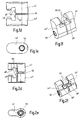
- Fig. 1a
- bis c eine Seitenansicht und zwei Längsschnitte einer Trennstelle eines Werkzeugsystems mit axialem Zugbolzen und radial betätigbarem Betätigungsmechanismus;
- Fig. 1d
- bis f zwei Seitenansichten und eine schaubildliche Darstellung der Spannelemente des Betätigungsmechanismus nach
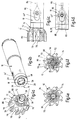
Fig. 1a bis c; - Fig. 2a
- bis c Darstellungen entsprechend
Fig. 1a bis c für ein weiteres Ausführungsbeispiel einer Trennstelle eines Werkzeugsystems mit axialem Zugbolzen; - Fig. 2d
- bis f zwei Seitenansichten und eine schaubildliche Darstellung der Spannelemente des Betätigungsmechanismus gemäß
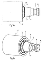
Fig. 2a bis c; - Fig. 3a
- und b eine Seitenansicht und eine schaubildliche Darstellung des Werkzeugkopfs nach
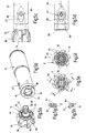
Fig. 1a bis c; - Fig. 4a
- und b zwei an einer Trennstelle miteinander verbindbare Teilelemente eines Werkzeugsystems mit integrierter Kühlmittelübergabe;
- Fig. 4c
- und d eine Seitenansicht der gekuppelten Teilelemente sowie eine Seitenansicht des ersten Teilelements des Werkzeugsystems nach
Fig. 4a und b mit angedeuteten Kühlmittelkanälen; - Fig. 4e
- eine Untenansicht des zweiten Teilelements nach
Fig. 4a ; - Fig. 4f
- eine Darstellung entsprechend
Fig. 4e mit eingezeichneten Kühlmittelkanälen; - Fig. 5a
- und b zwei an einer Trennstelle miteinander verbindbare Teilelemente eines Werkzeugsystems mit gegenüber
Fig. 4 abgewandelter Kühlmittelübergabe; - Fig. 5c
- und d eine Seitenansicht des gekuppelten Werkzeugsystems und des ersten Teilelements des Werkzeugsystems mit eingezeichneten Kühlmittelkanälen;
- Fig. 5e
- eine Untenansicht des zweiten Teilelements nach
Fig. 5a ; - Fig. 5f
- eine Darstellung entsprechend
Fig. 5e mit eingezeichneten Kühlmittelkanälen; - Fig. 5g
- und h Schnitte nach den Schnittlinien A-A und B-B der
Fig. 5e ; - Fig. 6a
- und b zwei Teilelemente eines Werkzeugsystems mit gegenüber
Fig. 4 und5 abgewandelter Kühlmittelführung; - Fig. 6c
- und d Seitenansichten der gekuppelten Teilelemente und des ersten Teilelements nach
Fig. 6a und b mit eingezeichneten Kühlmittelkanälen; - Fig. 6e
- eine Untenansicht des zweiten Teilelements gemäß
Fig. 6a ; - Fig. 6f
- eine Darstellung entsprechend
Fig. 6e mit eingezeichneten Kühlmittelkanälen; - Fig. 6g
- einen Schnitt entlang der Schnittlinien A-A der
Fig. 6e ; - Fig. 6h
- eine schaubildliche Stirnseitenansicht der miteinander gekuppelten Teilelemente nach
Fig. 6a und b.
- Fig. 1a
- to c is a side view and two longitudinal sections of a separation point of a tool system with axial Zugbolzen and radially operable actuating mechanism;
- Fig. 1d
- to f two side views and a perspective view of the clamping elements of the actuating mechanism according to
Fig. 1a to c; - Fig. 2a
- to c representations accordingly
Fig. 1a to c for a further embodiment of a separation point of a tool system with axial tension bolt; - Fig. 2d
- to f two side views and a perspective view of the clamping elements of the actuating mechanism according to
Fig. 2a to c; - Fig. 3a
- and b is a side view and a perspective view of the tool head according to
Fig. 1a to c; - Fig. 4a
- and b two partial elements of a tool system with integrated coolant transfer which can be connected to one another at a separation point;
- Fig. 4c
- and d is a side view of the coupled sub-elements and a side view of the first sub-element of the tool system according to
Fig. 4a and b with indicated coolant channels; - Fig. 4e
- a bottom view of the second subelement after
Fig. 4a ; - Fig. 4f
- a representation accordingly
Fig. 4e with marked coolant channels; - Fig. 5a
- and b two at a separation point connectable with each other sub-elements of a tool system with respect
Fig. 4 modified coolant transfer; - Fig. 5c
- and d is a side view of the coupled tooling system and the first sub-element of the tool system with indicated coolant channels;
- Fig. 5e
- a bottom view of the second subelement after
Fig. 5a ; - Fig. 5f
- a representation accordingly
Fig. 5e with marked coolant channels; - Fig. 5g
- and h cuts according to the section lines AA and BB of the
Fig. 5e ; - Fig. 6a
- and b two sub-elements of a tool system with opposite
Fig. 4 and5 modified coolant guide; - Fig. 6c
- and d side views of the coupled sub-elements and the first sub-element after
Fig. 6a and b with marked coolant channels; - Fig. 6e
- a bottom view of the second subelement according to
Fig. 6a ; - Fig. 6f
- a representation accordingly
Fig. 6e with marked coolant channels; - Fig. 6g
- a section along the section lines AA of
Fig. 6e ; - Fig. 6h
- a diagrammatic front view of the interconnected sub-elements according to
Fig. 6a and b.
Bei den in der Zeichnung dargestellten Werkzeugsystemen handelt es sich um Rundlaufwerkzeuge für den Einsatz in Werkzeugmaschinen, die beispielhaft als Reibwerkzeuge ausgebildet sind. Die Werkzeugsysteme bestehen im Wesentlichen aus einem ersten Teilelement 10, das bei dem gezeigten Ausführungsbeispiel als Werkzeughalter oder Maschinenspindel ausgebildet ist, einem zweiten Teilelement 12, das beispielhaft als Werkzeugkopf ausgebildet ist. Die beiden Teilelemente 10,12 sind an einer Trennstelle 14 lösbar miteinander verbunden. Außerdem findet an der Trennstelle 14 eine Kühlmittelübergabe vom ersten zum zweiten Teilelement 10,12 statt.The tool systems shown in the drawing are concentricity tools for use in machine tools, which are exemplary are designed as reaming tools. The tool systems consist essentially of a
Die Trennstelle 14 weist eine am ersten Teilelement 10 angeordnete, zur Drehachse 16 des Werkzeugsystems koaxiale Aufnahme 18 auf, die nach außen hin von einer ringförmigen Stirnfläche 20 begrenzt ist. Zur Trennstelle 14 gehört ferner die am zweiten Teilelement 12 angeordnete Kupplungspartie 22, die einen Kupplungszapfen 24 sowie eine zur ringförmigen Stirnfläche 20 des ersten Teilelements 10 weisende, in gekuppeltem Zustand gegen diese anliegende ringförmige Planfläche 26 aufweist. Die Aufnahme 18 weist in ihrem Inneren eine konische Aufnahmepartie 28 und eine zwischen der konischen Aufnahmepartie 28 und der Stirnfläche 20 angeordnete, als Mehrkantfläche ausgebildete Drehmitnahmepartie 30 auf, während der Kupplungszapfen eine zur konischen Aufnahmepartie 28 komplementäre Kegelfläche 32 sowie eine zwischen der Kegelfläche 32 und der Planfläche 26 angeordnete, zur Drehmitnahmepartie 30 komplementäre, mehrkantige Drehmitnehmerpartie 34 aufweist. Am freien Ende des Kupplungszapfens 24 steht ein Zugbolzen 36 axial über und greift im montierten Zustand in einen sich an die Aufnahme 18 anschließenden Hohlraum 38 des ersten Teilelements ein. Der Zugbolzen 36 ist mit einem axial überstehenden Gewindeschaft 40 in eine Gewindebohrung 42 des zweiten Teilelements eingedreht und dort starr befestigt. Die Trennstelle 14 weist außerdem Spannmittel 44 zum gegenseitigen Verspannen der Teilelemente 10,12 auf, die zwei im Bereich des Hohlraums 38 im ersten Teilelement 10 radial geführte Spannelemente 44',44" aufweist, die einander bezüglich der Drehachse 16 gegenüberliegend angeordnet sind und in der in
Eine Besonderheit der Erfindung besteht darin, dass die Spannelemente 44',44" mit Auswurfpartien 58 versehen sind, die beim Lösen der Spannelemente aus ihrer Spannstellung mit Hilfe der Differentialschraube 50 unter Ausübung einer in Auswurfrichtung des Kupplungsteils 22 wirkenden Axialkraft gegen eine den Spannelementen zugewandte Wirkfläche 58 des Zugbolzens 36 anschlagen. Die zugbolzenseitige Wirkfläche ist bei beiden Ausführungsformen nach
Das in
Eine weitere Besonderheit der Erfindung besteht in der Führung der Kühlmittelkanäle im Bereich der Trennstelle 14. Drei Ausführungsvarianten für die Kühlmittelführung finden sich in den Figurengruppen 4, 5 und 6. Auf der Seite des ersten Teilelements 10 stimmen die drei Ausführungsvarianten überein. Der zuführseitig zentral angeordnete Zuführkanal 64 wird zur Umfahrung der Spannelemente 44',44" in vier Teilkanäle 66 aufgeteilt, die an einer Übergangsstelle im Bereich der Stirnfläche 20 über vier Öffnungen 68 aus dem zweiten Teilelement austreten. Die drei Ausführungsvarianten nach
Im Falle der
Bei dem Ausführungsbeispiel nach
Bei dem Ausführungsbeispiel nach
Zusammenfassend ist folgendes festzuhalten: Die Erfindung bezieht sich auf eine Trennstelle 14 zwischen zwei Teilelementen 10,12 eines um eine Drehachse 16 drehenden Werkzeugsystems, insbesondere für den Einsatz in Werkzeugmaschinen. Die Trennstelle 14 umfasst eine an einem ersten Teilelement 10 angeordnete, zur Drehachse 16 koaxiale, zumindest teilweise konische Aufnahme 18, die von einer ringförmigen Stirnfläche 20 begrenzt ist. Das zweite Teilelement 12 trägt ein Kupplungsteil 22, das einen Kupplungszapfen 24 mit einer zur konischen Aufnahme 18 komplementäre Kegelfläche 32 und eine zur ringförmigen Stirnfläche 20 weisende, in gekuppeltem Zustand gegen diese anliegende ringförmige Planfläche 26 aufweist. Über das freie Ende des Kupplungszapfens 24 steht ein Zugbolzen 36 axial über, der in gekuppeltem Zustand in einen sich an die Aufnahme 18 anschließenden Hohlraum 38 eingreift. Weiter sind von der Außenseite her betätigbare Spannmittel zum gegenseitigen Verspannen der Teilelemente 10,12 vorgesehen, die zwei in im ersten Teilelement 10 radial geführte, am Zugbolzen 36 angreifende Spannelemente 44',44" aufweisen und die in Wirkverbindung mit gemeinsamen Betätigungsmitteln 50 stehen, durch die sie zwischen einer Lösestellung und einer Spannstellung verstellbar sind. Erfindungsgemäß sind die Spannelemente mit Auswurfpartien 60 versehen, die mit mindestens einem drehend gelagerten Wälzkörper 62 bestückt sein können. In summary, the following should be noted: The invention relates to a
Claims (20)
- Rotary tool system having a rotational axis (16) and a joint between two sub-elements (10, 12), in particular for use in machine tools, comprising: an at least partially conical receiver (18), which is arranged on a first sub-element (10) and is coaxial with the rotational axis (16), and which is delimited by an annular end face (20); a coupling part (22), which is arranged on a second sub-element (12) and has a coupling pin (24) with a conical surface (32) which is complementary to the conical receiver (18), and has an annular plane surface (26) which faces towards the annular end face (20) and which, in the coupled state, bears against the latter; a tie bolt 36, which projects axially over the free end of the coupling pin (24) and which in the coupled state engages in a cavity (38) adjoining the receiver (18); and clamping means, which can be actuated from the outside, for the purpose of mutual clamping of the sub-elements (10, 12), which clamping means have two clamping elements (44', 44") routed radially in the first sub-element (10) which are arranged opposite each other relative to the rotational axis (16) and in a clamping position carry wedge surfaces (48', 48") which engage beneath a conical portion (46) of the tie bolt (36) that is concentric with the rotational axis (16), and which are operatively connected to common actuating means (50), which are adjustable between a release position and a clamping position, characterized in that the clamping elements (44', 44") are provided with ejector portions (60) which, in the releasing of the clamping elements from the clamping position, with the exertion of an axial force acting in the ejection direction of the coupling part (22), strike against an active surface (58) of the tie bolt (36) which faces towards the clamping elements (44', 44").
- Rotary tool system according to Claim 1, characterized in that the active surface (58) on the tie bolt side and/or the ejector portions (60) on the clamping element side is/are equipped with at least one rotatably mounted rolling element (62).
- Rotary tool system according to Claim 2, characterized in that the rolling elements (62) are realized in a spherical, barrel-shaped or cylindrical form.
- Rotary tool system according to Claim 2 or 3,
characterized in that the active surface (58) on the tie bolt side constitutes an internal cone, and the clamping elements (44', 44") have an ejector portion (60) which, in the release operation, strikes against the internal cone and runs radially on the latter. - Rotary tool system according to any one of Claims 1 to 4, characterized in that the ejector portions (60) are formed, respectively, in the form of a projection or an inclined surface on the clamping elements (44', 44").
- Rotary tool system according to any one of Claims 1 to 5, characterized in that the clamping elements (44', 44") are routed in a floating manner in radial guides of the first sub-element (10).
- Rotary tool system according to any one of Claims 1 to 6, characterized in that the actuating means (50) are realized as a differential screw, respectively having a threaded portion (52', 52"), provided with contradirectional thread leads, which engage in the two clamping elements (44', 44").
- Rotary tool system according to any one of Claims 1 to 7, characterized in that arranged in the first sub-element (10) are stops (54), which delimit the motion path of the clamping elements (44', 44") in the release operation.
- Rotary tool system according to Claim 8, characterized in that the stops (54) are constituted by cap screws (56) which by means of their head engage in the motion path of the clamping elements.
- Rotary tool system according to any one of Claims 1 to 9, characterized in that a rotary driving portion (30, 34) is arranged in an intermediate region between the end face (20) and the plane surface (26) on the one hand and between the conical receiver (18) and the conical surface (32) on the other hand.
- Rotary tool system according to Claim 10, characterized in that the rotary driving portions (30, 34) of the receiver (18) and of the coupling pin (24) are realized as polygonal surfaces which are complementary to each other.
- Rotary tool system according to any one of Claims 1 to 11, characterized in that the actuating means (50) realized as a differential screw extends through the clamping elements (44', 44") outside the part which receives the tie bolt (36), and the transverse dimension of the clamping elements (44', 44") in the region of the actuating means (50) is greater than in the region of the parts comprising the tie bolt (36).
- Rotary tool system according to any one of Claims 1 to 12, characterized in that the sub-elements (10, 12) have cooling channels which communicate with each other, at least one intake channel (64, 66), routed around the clamping elements (44', 44") to a transfer location, being arranged in the first sub-element (10) and at least one supply channel (72, 82, 92), connected to the transfer location for a plurality of cutting elements (80), being arranged in the second sub-element (12).
- Rotary tool system according to Claim 13, characterized in that the transition location is realized as an annular channel (70) communicating with the at least one intake channel (64, 66) and the at least one supply channel (72).
- Rotary tool system according to Claim 14, characterized in that the annular channel (70) is delimited by a circumferential groove in one of the sub-elements (12) and by a parting surface (20) overlapping the groove in the other sub-element (10).
- Rotary tool system according to Claim 13, characterized in that the transition location is constituted by congruent transition openings in the two sub-elements (10, 12).
- Rotary tool system according to Claim 16, characterized in that the supply channels (72, 82, 92) branched-off from the transition openings emerge in the region of cutting elements (80) in the second sub-element (12).
- Rotary tool system according to any one of Claims 12 to 17, characterized by a distributor piece (100) which engages in the supply channel (92) and which comprises distributor grooves (102) leading to the individual cutting elements (80) and communicating with the supply channel (92).
- Rotary tool system according to Claim 18, characterized in that the distributor piece (100) has a plug-in pin (104) which engages in the second sub-element (12) with a predefined rotational orientation.
- Rotary tool system according to any one of Claims 1 to 19, characterized in that the first sub-element (10) is realized as a machine spindle, an adapter piece or a tool holder, and the second sub-element (12) is realized as a tool head.
Priority Applications (1)
| Application Number | Priority Date | Filing Date | Title |
|---|---|---|---|
| PL07729731T PL2032295T3 (en) | 2006-06-19 | 2007-05-31 | Junction between two components of a rotating tool system |
Applications Claiming Priority (2)
| Application Number | Priority Date | Filing Date | Title |
|---|---|---|---|
| DE102006028373.2A DE102006028373B4 (en) | 2006-06-19 | 2006-06-19 | Rotating tool system with a separation point between two sub-elements |
| PCT/EP2007/055328 WO2007147711A1 (en) | 2006-06-19 | 2007-05-31 | Junction between two components of a rotating tool system |
Publications (2)
| Publication Number | Publication Date |
|---|---|
| EP2032295A1 EP2032295A1 (en) | 2009-03-11 |
| EP2032295B1 true EP2032295B1 (en) | 2010-01-27 |
Family
ID=38372516
Family Applications (1)
| Application Number | Title | Priority Date | Filing Date |
|---|---|---|---|
| EP07729731A Active EP2032295B1 (en) | 2006-06-19 | 2007-05-31 | Junction between two components of a rotating tool system |
Country Status (10)
| Country | Link |
|---|---|
| US (2) | US8172490B2 (en) |
| EP (1) | EP2032295B1 (en) |
| JP (1) | JP5331684B2 (en) |
| CN (1) | CN101360578B (en) |
| AT (1) | ATE456412T1 (en) |
| DE (3) | DE102006028373B4 (en) |
| ES (1) | ES2338274T3 (en) |
| IL (1) | IL191739A0 (en) |
| PL (1) | PL2032295T3 (en) |
| WO (1) | WO2007147711A1 (en) |
Cited By (2)
| Publication number | Priority date | Publication date | Assignee | Title |
|---|---|---|---|---|
| EP2641679A2 (en) | 2012-03-23 | 2013-09-25 | Gühring OHG | Interface between two system modules of a tool system |
| CN107740819A (en) * | 2017-11-01 | 2018-02-27 | 镇江索达联轴器有限公司 | A kind of tapered shaft shaft coupling |
Families Citing this family (22)
| Publication number | Priority date | Publication date | Assignee | Title |
|---|---|---|---|---|
| US8033766B2 (en) * | 2008-05-09 | 2011-10-11 | Kennametal Inc. | Tool holder with ball clamping mechanism |
| US8257003B2 (en) * | 2008-12-05 | 2012-09-04 | Kennametal Inc. | Side actuated collet lock mechanism |
| US8998545B2 (en) | 2009-01-16 | 2015-04-07 | John Wayne Stoneback | Retention knob for tool holder |
| DE102009012433A1 (en) * | 2009-03-10 | 2010-09-16 | Kennametal Inc. | Cutting tool for a machine tool |
| DE102009042395A1 (en) * | 2009-09-16 | 2011-03-24 | Hartmetall-Werkzeugfabrik Paul Horn Gmbh | Reaming tool for machining a workpiece |
| DE102010046044A1 (en) * | 2009-09-22 | 2011-04-21 | Gühring Ohg | reamer |
| US20110135416A1 (en) * | 2009-12-04 | 2011-06-09 | Precision Drive Systems, LLC | Spindle apparatus for receiving and driving a tool holder |
| DE102010018254B4 (en) * | 2010-04-23 | 2022-11-10 | Kennametal Inc. | coolant distributor |
| SE537368C2 (en) * | 2011-04-29 | 2015-04-14 | Sandvik Intellectual Property | Milling tools with a sealing cap |
| CN104428087B (en) * | 2012-05-29 | 2017-06-06 | 株式会社泰珂洛 | Link device and cutting element |
| CN104767318B (en) * | 2014-01-06 | 2017-05-03 | 和舰科技(苏州)有限公司 | Power device |
| DE102014211410B3 (en) * | 2014-06-13 | 2015-11-26 | NUBIUS GROUP Präzisionswerkzeuge GmbH | Tool holder with coolant supply via ring channel |
| DE102014211420B3 (en) * | 2014-06-13 | 2015-11-05 | NUBIUS GROUP Präzisionswerkzeuge GmbH | Coupling with ring channel |
| DE102016105210A1 (en) | 2016-03-21 | 2017-09-21 | Komet Group Gmbh | Machining tool |
| EP3456446A1 (en) * | 2017-09-15 | 2019-03-20 | Sandvik Intellectual Property AB | Cutting tool part assembly |
| US11219987B2 (en) | 2019-06-06 | 2022-01-11 | George R Anex | Tool for installation and removal of retention knobs |
| EP3825045B1 (en) * | 2019-11-22 | 2022-08-10 | Seco Tools Ab | A cutting tool assembly |
| CN110883380B (en) * | 2019-11-28 | 2021-01-29 | 株洲钻石切削刀具股份有限公司 | Composite cutting tool |
| DE102020120525A1 (en) * | 2020-08-04 | 2022-02-10 | Ott-Jakob Spanntechnik Gmbh | Tool or workpiece holder |
| DE112021004391T5 (en) * | 2020-08-21 | 2023-06-01 | Kyocera Corporation | Cutting insert, rotary tool and method of making a machined product |
| US20240024958A1 (en) * | 2022-07-20 | 2024-01-25 | Kennametal Inc. | Cutting tool with modular pocket wall |
| CN115430853B (en) * | 2022-10-28 | 2023-05-23 | 广东希普斯科技有限公司 | Inner-cooling type multifunctional ultrahigh precision chuck |
Family Cites Families (23)
| Publication number | Priority date | Publication date | Assignee | Title |
|---|---|---|---|---|
| US2383688A (en) * | 1943-07-26 | 1945-08-28 | Tungsten Carbide Tool Company | Boring tool |
| US2485799A (en) * | 1946-08-07 | 1949-10-25 | Giddings & Lewis | Toolhead |
| US2684249A (en) * | 1950-11-30 | 1954-07-20 | Giddings & Lewis | Toolhead and taper shank adapter |
| US2893291A (en) * | 1956-07-20 | 1959-07-07 | Morey Machinery Co Inc | Draw toggles for spindle male tapers of milling and the like machines |
| US3341921A (en) * | 1966-01-10 | 1967-09-19 | Gen Electric | Cutting insert |
| JPS5419254A (en) * | 1977-07-14 | 1979-02-13 | Shirakawa Seisakushiyo Kk | Continuous dehumidifier |
| JPS5639845A (en) * | 1979-08-31 | 1981-04-15 | Hino Motors Ltd | Retainer for tool holder |
| SE427732B (en) | 1979-09-20 | 1983-05-02 | Sandvik Ab | tool holder |
| US4577875A (en) * | 1982-10-29 | 1986-03-25 | Miyakawa Industry Co., Ltd. | Exchange chuck for a tool |
| JPS58173446U (en) * | 1983-03-28 | 1983-11-19 | 日野自動車株式会社 | Tool holder holding device |
| US4575293A (en) * | 1984-07-12 | 1986-03-11 | Mario Berti | Machine tool holder having opposed ramp members |
| US4729702A (en) * | 1986-10-10 | 1988-03-08 | Carboloy Inc. | Clamping means for taper tool shanks |
| DE3711808A1 (en) * | 1987-04-08 | 1988-10-20 | Walter Gmbh Montanwerke | MULTI-PIECE CLAMPING SYSTEM, IN PARTICULAR FOR ROTARY TOOLS |
| US4829862A (en) * | 1987-08-17 | 1989-05-16 | Carboloy Inc. | Modular locking system |
| KR890015820A (en) * | 1988-04-28 | 1989-11-25 | 야스이 요시히로 | Processing liquid supply device |
| JP2681998B2 (en) * | 1988-04-28 | 1997-11-26 | ブラザー工業株式会社 | Processing fluid supply device |
| US4919574A (en) * | 1989-03-31 | 1990-04-24 | Illinois Tool Works Inc. | Tool holder retention system |
| DE9006877U1 (en) * | 1990-06-19 | 1990-08-23 | Wilhelm Fette Gmbh, 2053 Schwarzenbek, De | |
| DE4019506A1 (en) * | 1990-06-19 | 1992-01-02 | Fette Wilhelm Gmbh | RECORDING WITH A THORN FOR CUTTING MACHINE TOOLS WITH INTERNAL HOLE AND MACHINE TOOL |
| JPH0636706U (en) * | 1992-10-20 | 1994-05-17 | 大昭和精機株式会社 | Tool holder mounting device |
| DE29612743U1 (en) * | 1996-07-23 | 1997-11-27 | Fahrion Eugen Gmbh | Chuck |
| DE10048910A1 (en) | 2000-10-02 | 2002-05-02 | Mapal Fab Praezision | junction |
| CN2673563Y (en) * | 2003-12-19 | 2005-01-26 | 萧如崧 | Main shaft locking tool withdraw mechanism |
-
2006
- 2006-06-19 DE DE102006028373.2A patent/DE102006028373B4/en active Active
-
2007
- 2007-05-31 JP JP2009515808A patent/JP5331684B2/en active Active
- 2007-05-31 WO PCT/EP2007/055328 patent/WO2007147711A1/en active Application Filing
- 2007-05-31 DE DE502007002751T patent/DE502007002751D1/en active Active
- 2007-05-31 ES ES07729731T patent/ES2338274T3/en active Active
- 2007-05-31 CN CN2007800017782A patent/CN101360578B/en active Active
- 2007-05-31 PL PL07729731T patent/PL2032295T3/en unknown
- 2007-05-31 US US12/084,678 patent/US8172490B2/en active Active
- 2007-05-31 EP EP07729731A patent/EP2032295B1/en active Active
- 2007-05-31 DE DE202007019172U patent/DE202007019172U1/en not_active Expired - Lifetime
- 2007-05-31 AT AT07729731T patent/ATE456412T1/en active
-
2008
- 2008-05-27 IL IL191739A patent/IL191739A0/en active IP Right Grant
-
2012
- 2012-04-17 US US13/448,940 patent/US20120200050A1/en not_active Abandoned
Cited By (3)
| Publication number | Priority date | Publication date | Assignee | Title |
|---|---|---|---|---|
| EP2641679A2 (en) | 2012-03-23 | 2013-09-25 | Gühring OHG | Interface between two system modules of a tool system |
| DE102012214923A1 (en) | 2012-03-23 | 2013-09-26 | Gühring Ohg | Interface between two system modules of a tool system |
| CN107740819A (en) * | 2017-11-01 | 2018-02-27 | 镇江索达联轴器有限公司 | A kind of tapered shaft shaft coupling |
Also Published As
| Publication number | Publication date |
|---|---|
| US8172490B2 (en) | 2012-05-08 |
| ATE456412T1 (en) | 2010-02-15 |
| PL2032295T3 (en) | 2010-07-30 |
| DE102006028373B4 (en) | 2016-01-21 |
| DE502007002751D1 (en) | 2010-03-18 |
| WO2007147711A1 (en) | 2007-12-27 |
| DE102006028373A1 (en) | 2007-12-20 |
| CN101360578B (en) | 2010-12-08 |
| EP2032295A1 (en) | 2009-03-11 |
| CN101360578A (en) | 2009-02-04 |
| DE202007019172U1 (en) | 2010-12-02 |
| US20120200050A1 (en) | 2012-08-09 |
| JP2009541072A (en) | 2009-11-26 |
| JP5331684B2 (en) | 2013-10-30 |
| ES2338274T3 (en) | 2010-05-05 |
| IL191739A0 (en) | 2008-12-29 |
| US20090283975A1 (en) | 2009-11-19 |
Similar Documents
| Publication | Publication Date | Title |
|---|---|---|
| EP2032295B1 (en) | Junction between two components of a rotating tool system | |
| EP1474258B1 (en) | Machine reamer | |
| EP0956920B2 (en) | Chuck for rotary tools, specially drills, taps and others | |
| DE3448086C2 (en) | ||
| WO1990012193A1 (en) | Coupling for drilling machine with dust extractor | |
| EP1166932A1 (en) | Spindle in a machine tool | |
| WO2010006964A1 (en) | Boring tool | |
| EP1896207A1 (en) | Interface of a tool system | |
| DE4032176C2 (en) | Slicer | |
| EP1609550A1 (en) | Coupling system and tool component | |
| DE10157450B4 (en) | Arrangement for feeding coolant or lubricant into tools | |
| DE69700028T2 (en) | Clamping device for tool holder with hollow cone | |
| DE3004077C2 (en) | Drill bit | |
| DE102013104874B3 (en) | tool turret | |
| DE102012212677B4 (en) | Honing tool, in particular for position honing | |
| DE102009044995B4 (en) | Cutting insert carrier, cutting insert and rotary driven cutting tool | |
| DE19818148B4 (en) | jig | |
| DE102007057640B3 (en) | Tool clamping device for tool holder of star wheel turret, has spring elements through which stopping unit with holder is held under tension in lateral arrangement at contact surface, where holder is inserted in retainer of tool carrier | |
| DD149621A5 (en) | HOLDER AND CONTRACTOR FOR ROTATABLE CUTTING TOOLS | |
| EP2897751B1 (en) | Machining tool which is drivable in rotation | |
| DE19918638C2 (en) | Connector for a drill for drilling holes in bone tissue, drill and drill | |
| DE102011005052A1 (en) | Clamping system for releasably connecting two preferably rotationally symmetrical parts | |
| DE19831743A1 (en) | Workpiece machining device | |
| EP1152856A1 (en) | Device for detachably connecting a tool | |
| DE102006052051A1 (en) | toolholder |
Legal Events
| Date | Code | Title | Description |
|---|---|---|---|
| PUAI | Public reference made under article 153(3) epc to a published international application that has entered the european phase |
Free format text: ORIGINAL CODE: 0009012 |
|
| 17P | Request for examination filed |
Effective date: 20080319 |
|
| AK | Designated contracting states |
Kind code of ref document: A1 Designated state(s): AT BE BG CH CY CZ DE DK EE ES FI FR GB GR HU IE IS IT LI LT LU LV MC MT NL PL PT RO SE SI SK TR |
|
| AX | Request for extension of the european patent |
Extension state: AL BA HR MK RS |
|
| 17Q | First examination report despatched |
Effective date: 20090505 |
|
| RAP1 | Party data changed (applicant data changed or rights of an application transferred) |
Owner name: KOMET GROUP GMBH |
|
| GRAP | Despatch of communication of intention to grant a patent |
Free format text: ORIGINAL CODE: EPIDOSNIGR1 |
|
| GRAS | Grant fee paid |
Free format text: ORIGINAL CODE: EPIDOSNIGR3 |
|
| GRAA | (expected) grant |
Free format text: ORIGINAL CODE: 0009210 |
|
| AK | Designated contracting states |
Kind code of ref document: B1 Designated state(s): AT BE BG CH CY CZ DE DK EE ES FI FR GB GR HU IE IS IT LI LT LU LV MC MT NL PL PT RO SE SI SK TR |
|
| REG | Reference to a national code |
Ref country code: GB Ref legal event code: FG4D Free format text: NOT ENGLISH |
|
| REG | Reference to a national code |
Ref country code: CH Ref legal event code: EP |
|
| REG | Reference to a national code |
Ref country code: IE Ref legal event code: FG4D |
|
| REF | Corresponds to: |
Ref document number: 502007002751 Country of ref document: DE Date of ref document: 20100318 Kind code of ref document: P |
|
| REG | Reference to a national code |
Ref country code: NL Ref legal event code: T3 |
|
| REG | Reference to a national code |
Ref country code: ES Ref legal event code: FG2A Ref document number: 2338274 Country of ref document: ES Kind code of ref document: T3 |
|
| REG | Reference to a national code |
Ref country code: SE Ref legal event code: TRGR |
|
| LTIE | Lt: invalidation of european patent or patent extension |
Effective date: 20100127 |
|
| PG25 | Lapsed in a contracting state [announced via postgrant information from national office to epo] |
Ref country code: LT Free format text: LAPSE BECAUSE OF FAILURE TO SUBMIT A TRANSLATION OF THE DESCRIPTION OR TO PAY THE FEE WITHIN THE PRESCRIBED TIME-LIMIT Effective date: 20100127 Ref country code: IS Free format text: LAPSE BECAUSE OF FAILURE TO SUBMIT A TRANSLATION OF THE DESCRIPTION OR TO PAY THE FEE WITHIN THE PRESCRIBED TIME-LIMIT Effective date: 20100527 Ref country code: PT Free format text: LAPSE BECAUSE OF FAILURE TO SUBMIT A TRANSLATION OF THE DESCRIPTION OR TO PAY THE FEE WITHIN THE PRESCRIBED TIME-LIMIT Effective date: 20100527 |
|
| REG | Reference to a national code |
Ref country code: PL Ref legal event code: T3 |
|
| REG | Reference to a national code |
Ref country code: IE Ref legal event code: FD4D |
|
| REG | Reference to a national code |
Ref country code: HU Ref legal event code: AG4A Ref document number: E007924 Country of ref document: HU |
|
| PG25 | Lapsed in a contracting state [announced via postgrant information from national office to epo] |
Ref country code: LV Free format text: LAPSE BECAUSE OF FAILURE TO SUBMIT A TRANSLATION OF THE DESCRIPTION OR TO PAY THE FEE WITHIN THE PRESCRIBED TIME-LIMIT Effective date: 20100127 Ref country code: SI Free format text: LAPSE BECAUSE OF FAILURE TO SUBMIT A TRANSLATION OF THE DESCRIPTION OR TO PAY THE FEE WITHIN THE PRESCRIBED TIME-LIMIT Effective date: 20100127 Ref country code: FI Free format text: LAPSE BECAUSE OF FAILURE TO SUBMIT A TRANSLATION OF THE DESCRIPTION OR TO PAY THE FEE WITHIN THE PRESCRIBED TIME-LIMIT Effective date: 20100127 |
|
| PG25 | Lapsed in a contracting state [announced via postgrant information from national office to epo] |
Ref country code: EE Free format text: LAPSE BECAUSE OF FAILURE TO SUBMIT A TRANSLATION OF THE DESCRIPTION OR TO PAY THE FEE WITHIN THE PRESCRIBED TIME-LIMIT Effective date: 20100127 Ref country code: GR Free format text: LAPSE BECAUSE OF FAILURE TO SUBMIT A TRANSLATION OF THE DESCRIPTION OR TO PAY THE FEE WITHIN THE PRESCRIBED TIME-LIMIT Effective date: 20100428 Ref country code: IE Free format text: LAPSE BECAUSE OF FAILURE TO SUBMIT A TRANSLATION OF THE DESCRIPTION OR TO PAY THE FEE WITHIN THE PRESCRIBED TIME-LIMIT Effective date: 20100127 Ref country code: RO Free format text: LAPSE BECAUSE OF FAILURE TO SUBMIT A TRANSLATION OF THE DESCRIPTION OR TO PAY THE FEE WITHIN THE PRESCRIBED TIME-LIMIT Effective date: 20100127 Ref country code: CY Free format text: LAPSE BECAUSE OF FAILURE TO SUBMIT A TRANSLATION OF THE DESCRIPTION OR TO PAY THE FEE WITHIN THE PRESCRIBED TIME-LIMIT Effective date: 20100127 |
|
| BERE | Be: lapsed |
Owner name: KOMET GROUP G.M.B.H. Effective date: 20100531 |
|
| PG25 | Lapsed in a contracting state [announced via postgrant information from national office to epo] |
Ref country code: SK Free format text: LAPSE BECAUSE OF FAILURE TO SUBMIT A TRANSLATION OF THE DESCRIPTION OR TO PAY THE FEE WITHIN THE PRESCRIBED TIME-LIMIT Effective date: 20100127 Ref country code: BG Free format text: LAPSE BECAUSE OF FAILURE TO SUBMIT A TRANSLATION OF THE DESCRIPTION OR TO PAY THE FEE WITHIN THE PRESCRIBED TIME-LIMIT Effective date: 20100427 |
|
| PLBE | No opposition filed within time limit |
Free format text: ORIGINAL CODE: 0009261 |
|
| STAA | Information on the status of an ep patent application or granted ep patent |
Free format text: STATUS: NO OPPOSITION FILED WITHIN TIME LIMIT |
|
| PG25 | Lapsed in a contracting state [announced via postgrant information from national office to epo] |
Ref country code: MC Free format text: LAPSE BECAUSE OF NON-PAYMENT OF DUE FEES Effective date: 20100531 |
|
| 26N | No opposition filed |
Effective date: 20101028 |
|
| PG25 | Lapsed in a contracting state [announced via postgrant information from national office to epo] |
Ref country code: DK Free format text: LAPSE BECAUSE OF FAILURE TO SUBMIT A TRANSLATION OF THE DESCRIPTION OR TO PAY THE FEE WITHIN THE PRESCRIBED TIME-LIMIT Effective date: 20100127 |
|
| PG25 | Lapsed in a contracting state [announced via postgrant information from national office to epo] |
Ref country code: IT Free format text: LAPSE BECAUSE OF NON-PAYMENT OF DUE FEES Effective date: 20100531 Ref country code: BE Free format text: LAPSE BECAUSE OF NON-PAYMENT OF DUE FEES Effective date: 20100531 |
|
| PG25 | Lapsed in a contracting state [announced via postgrant information from national office to epo] |
Ref country code: MT Free format text: LAPSE BECAUSE OF FAILURE TO SUBMIT A TRANSLATION OF THE DESCRIPTION OR TO PAY THE FEE WITHIN THE PRESCRIBED TIME-LIMIT Effective date: 20100127 |
|
| PGFP | Annual fee paid to national office [announced via postgrant information from national office to epo] |
Ref country code: HU Payment date: 20120529 Year of fee payment: 6 |
|
| PG25 | Lapsed in a contracting state [announced via postgrant information from national office to epo] |
Ref country code: LU Free format text: LAPSE BECAUSE OF NON-PAYMENT OF DUE FEES Effective date: 20100531 |
|
| PG25 | Lapsed in a contracting state [announced via postgrant information from national office to epo] |
Ref country code: TR Free format text: LAPSE BECAUSE OF FAILURE TO SUBMIT A TRANSLATION OF THE DESCRIPTION OR TO PAY THE FEE WITHIN THE PRESCRIBED TIME-LIMIT Effective date: 20100127 |
|
| PGFP | Annual fee paid to national office [announced via postgrant information from national office to epo] |
Ref country code: NL Payment date: 20130523 Year of fee payment: 7 |
|
| PG25 | Lapsed in a contracting state [announced via postgrant information from national office to epo] |
Ref country code: HU Free format text: LAPSE BECAUSE OF NON-PAYMENT OF DUE FEES Effective date: 20130601 |
|
| REG | Reference to a national code |
Ref country code: NL Ref legal event code: V1 Effective date: 20141201 |
|
| PG25 | Lapsed in a contracting state [announced via postgrant information from national office to epo] |
Ref country code: NL Free format text: LAPSE BECAUSE OF NON-PAYMENT OF DUE FEES Effective date: 20141201 |
|
| REG | Reference to a national code |
Ref country code: FR Ref legal event code: PLFP Year of fee payment: 10 |
|
| REG | Reference to a national code |
Ref country code: FR Ref legal event code: PLFP Year of fee payment: 11 |
|
| REG | Reference to a national code |
Ref country code: FR Ref legal event code: PLFP Year of fee payment: 12 |
|
| PGFP | Annual fee paid to national office [announced via postgrant information from national office to epo] |
Ref country code: IT Payment date: 20230526 Year of fee payment: 17 Ref country code: FR Payment date: 20230525 Year of fee payment: 17 Ref country code: DE Payment date: 20230519 Year of fee payment: 17 Ref country code: CZ Payment date: 20230523 Year of fee payment: 17 Ref country code: CH Payment date: 20230605 Year of fee payment: 17 |
|
| PGFP | Annual fee paid to national office [announced via postgrant information from national office to epo] |
Ref country code: SE Payment date: 20230420 Year of fee payment: 17 Ref country code: PL Payment date: 20230522 Year of fee payment: 17 Ref country code: AT Payment date: 20230522 Year of fee payment: 17 |
|
| PGFP | Annual fee paid to national office [announced via postgrant information from national office to epo] |
Ref country code: GB Payment date: 20230523 Year of fee payment: 17 Ref country code: ES Payment date: 20230724 Year of fee payment: 17 |