EP2031166A2 - Türband mit Elektroleitung - Google Patents
Türband mit Elektroleitung Download PDFInfo
- Publication number
- EP2031166A2 EP2031166A2 EP08013429A EP08013429A EP2031166A2 EP 2031166 A2 EP2031166 A2 EP 2031166A2 EP 08013429 A EP08013429 A EP 08013429A EP 08013429 A EP08013429 A EP 08013429A EP 2031166 A2 EP2031166 A2 EP 2031166A2
- Authority
- EP
- European Patent Office
- Prior art keywords
- door
- door hinge
- housing
- connecting elements
- rotation
- Prior art date
- Legal status (The legal status is an assumption and is not a legal conclusion. Google has not performed a legal analysis and makes no representation as to the accuracy of the status listed.)
- Granted
Links
- 239000004020 conductor Substances 0.000 claims abstract 3
- WYTGDNHDOZPMIW-RCBQFDQVSA-N alstonine Natural products C1=CC2=C3C=CC=CC3=NC2=C2N1C[C@H]1[C@H](C)OC=C(C(=O)OC)[C@H]1C2 WYTGDNHDOZPMIW-RCBQFDQVSA-N 0.000 claims 1
- 238000004512 die casting Methods 0.000 description 3
- 239000002184 metal Substances 0.000 description 2
- 229910052751 metal Inorganic materials 0.000 description 2
- 238000007665 sagging Methods 0.000 description 2
- HCHKCACWOHOZIP-UHFFFAOYSA-N Zinc Chemical compound [Zn] HCHKCACWOHOZIP-UHFFFAOYSA-N 0.000 description 1
- 238000009434 installation Methods 0.000 description 1
- 230000001681 protective effect Effects 0.000 description 1
- 230000007704 transition Effects 0.000 description 1
- 229910052725 zinc Inorganic materials 0.000 description 1
- 239000011701 zinc Substances 0.000 description 1
Images
Classifications
-
- E—FIXED CONSTRUCTIONS
- E05—LOCKS; KEYS; WINDOW OR DOOR FITTINGS; SAFES
- E05D—HINGES OR SUSPENSION DEVICES FOR DOORS, WINDOWS OR WINGS
- E05D11/00—Additional features or accessories of hinges
- E05D11/0081—Additional features or accessories of hinges for transmitting energy, e.g. electrical cable routing
-
- E—FIXED CONSTRUCTIONS
- E05—LOCKS; KEYS; WINDOW OR DOOR FITTINGS; SAFES
- E05D—HINGES OR SUSPENSION DEVICES FOR DOORS, WINDOWS OR WINGS
- E05D3/00—Hinges with pins
- E05D3/06—Hinges with pins with two or more pins
- E05D3/18—Hinges with pins with two or more pins with sliding pins or guides
- E05D3/186—Scissors hinges, with two crossing levers and five parallel pins
-
- E—FIXED CONSTRUCTIONS
- E05—LOCKS; KEYS; WINDOW OR DOOR FITTINGS; SAFES
- E05D—HINGES OR SUSPENSION DEVICES FOR DOORS, WINDOWS OR WINGS
- E05D7/00—Hinges or pivots of special construction
- E05D7/04—Hinges adjustable relative to the wing or the frame
- E05D2007/0469—Hinges adjustable relative to the wing or the frame in an axial direction
-
- E—FIXED CONSTRUCTIONS
- E05—LOCKS; KEYS; WINDOW OR DOOR FITTINGS; SAFES
- E05D—HINGES OR SUSPENSION DEVICES FOR DOORS, WINDOWS OR WINGS
- E05D7/00—Hinges or pivots of special construction
- E05D7/04—Hinges adjustable relative to the wing or the frame
- E05D2007/0484—Hinges adjustable relative to the wing or the frame in a radial direction
-
- E—FIXED CONSTRUCTIONS
- E05—LOCKS; KEYS; WINDOW OR DOOR FITTINGS; SAFES
- E05Y—INDEXING SCHEME ASSOCIATED WITH SUBCLASSES E05D AND E05F, RELATING TO CONSTRUCTION ELEMENTS, ELECTRIC CONTROL, POWER SUPPLY, POWER SIGNAL OR TRANSMISSION, USER INTERFACES, MOUNTING OR COUPLING, DETAILS, ACCESSORIES, AUXILIARY OPERATIONS NOT OTHERWISE PROVIDED FOR, APPLICATION THEREOF
- E05Y2800/00—Details, accessories and auxiliary operations not otherwise provided for
- E05Y2800/20—Combinations of elements
- E05Y2800/205—Combinations of elements forming a unit
-
- E—FIXED CONSTRUCTIONS
- E05—LOCKS; KEYS; WINDOW OR DOOR FITTINGS; SAFES
- E05Y—INDEXING SCHEME ASSOCIATED WITH SUBCLASSES E05D AND E05F, RELATING TO CONSTRUCTION ELEMENTS, ELECTRIC CONTROL, POWER SUPPLY, POWER SIGNAL OR TRANSMISSION, USER INTERFACES, MOUNTING OR COUPLING, DETAILS, ACCESSORIES, AUXILIARY OPERATIONS NOT OTHERWISE PROVIDED FOR, APPLICATION THEREOF
- E05Y2800/00—Details, accessories and auxiliary operations not otherwise provided for
- E05Y2800/20—Combinations of elements
- E05Y2800/21—Combinations of elements of identical elements, e.g. of identical compression springs
-
- E—FIXED CONSTRUCTIONS
- E05—LOCKS; KEYS; WINDOW OR DOOR FITTINGS; SAFES
- E05Y—INDEXING SCHEME ASSOCIATED WITH SUBCLASSES E05D AND E05F, RELATING TO CONSTRUCTION ELEMENTS, ELECTRIC CONTROL, POWER SUPPLY, POWER SIGNAL OR TRANSMISSION, USER INTERFACES, MOUNTING OR COUPLING, DETAILS, ACCESSORIES, AUXILIARY OPERATIONS NOT OTHERWISE PROVIDED FOR, APPLICATION THEREOF
- E05Y2900/00—Application of doors, windows, wings or fittings thereof
- E05Y2900/10—Application of doors, windows, wings or fittings thereof for buildings or parts thereof
- E05Y2900/13—Type of wing
- E05Y2900/132—Doors
Definitions
- the invention relates to a door hinge for a concealed with the door closed arrangement between the door frame and door with a flexibly guided through the door hinge through electrical line.
- the basic structure of the door hinge includes two housing parts which are insertable into recesses in the door frame and in the door and have a receiving space bounded by a rear side for connecting elements, and connecting elements which are pivotally connected about a vertical axis of rotation and having connection ends which are in the receiving spaces are mounted on the housing parts.
- a connection end of the connecting elements is arranged pivotable about a housing-fixed axis of rotation.
- the other terminal end of the connecting elements is slidably guided in the associated receiving space along a longitudinal guide which extends from the front of the receiving spaces to the rear.
- a door hinge with the features described above is made EP 1 489 255 B1 known.
- the electrical line is guided through holes in mounting flanges of the housing parts and allows an electrical power supply from the door frame side to the door leaf side to provide power consumers on the door leaf as inconspicuous as possible through the door hinge with power.
- the electrical line In the closed state of the door, the electrical line is indeed covered and protected, but by the opening movement of the door, the electrical line is visible and thus vulnerable to negligent or intentional damage.
- An additionally provided protective line should prevent this. As a result, complex constructive measures are necessary to move the electrical line zugok safely and protect.
- the invention has for its object to simplify the implementation of the electrical line and to ensure proper management of the electrical line with structurally simple means. Furthermore, the electric cable should not be visible when opening and closing the door.
- the invention is achieved according to the invention in a door hinge with the features described above in that the backs of the receiving spaces have openings for the electric line in the form of Langlöchem, which extend parallel to the housing-fixed axis of rotation, and that the electric line consists of a flat band, which by the slots and the door hinge is passed.
- the ribbon is flexible and has sufficient rigidity so that it can balance the opening and closing movements of the door. There is no danger that the flat strip kinks or is crushed between parts of the door hinge. A failure of the power supply by cable breakage of the ribbon is thereby excluded.
- the inventive arrangement is particularly suitable for door hinges with small dimensions.
- the ribbon can be easily pulled into the door hinge. Since the housing parts of the door hinge can be manufactured as metal die castings, it requires only minor constructive measures on the molds to attach the passage openings on the backs of the receiving spaces of the housing parts.
- the flat band is guided snake-like around the fixed axes of rotation of the door hinge, wherein the flat strip is passed in the region of the receiving spaces between an inner surface of the receiving space and the respective adjacent fixed axis of rotation or longitudinally displaceable axis of rotation.
- the guide helps to make the flat band reserves its defined position during opening and closing movements of the door hinge and can not be kinked or crushed between parts of the door hinge. A protection of the electrical line from damage is ensured in this way even with a door opening by 180 °. It should also be emphasized that the electrical line in the transition region between the door frame and door leaf is covered by the connecting elements of the door hinge, since the passage openings are provided for the electrical line at the level of the connecting elements.
- the housing parts expediently have an upper and a lower mounting flange.
- the mounting flanges of the door frame side housing part may have vertically extending slots for a height adjustment of the door hinge.
- the oblong holes are penetrated by screws, which are screwed into the door frame. A continuous height adjustment of the door hinge and thus also of the door leaf can be carried out when the screws are loosened.
- the mounting flanges are knurled at least the tärargen detaileden housing part on your back pages.
- the knurled backs of the mounting flanges results in improved protection against sagging of the door hinge in case of insufficient attachment by insufficiently tightened screws.
- the arrangement of the door hinge in the door frame is basically more stable because of the knurled backs of the mounting flanges.
- the tzargen in the door leaf-side housing part on a lower and an upper adjustment device for horizontal adjustment of the door leaf with respect to the door frame.
- the connection ends of the connecting elements are mounted, so that an optimal adjustment of the Door leaf in the width direction of the door, taking into account arranged around the housing-fixed axis of rotation connecting end and the sliding in the longitudinal guide connection end is possible.
- the tzargen in a further preferred embodiment of the invention, the tzargen savede or the door leaf-side housing part on a lower and an upper adjusting device for adjusting the Schoerielanyakes. Also at this adjustment the connection ends of the connecting elements are mounted.
- the Materielantik is thus also best possible adjustable taking into account the respective position of the terminal ends. Due to the adjustment options for the vertical or horizontal position of the door leaf results in total, together with the adjustment for the door leaf pressure a three-dimensional adjustability of the door hinge according to the invention.
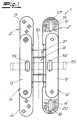
- the figures show a door hinge 1 for a concealed with the door closed arrangement between the door frame and door.
- the door hinge has two housing parts 2, 2 ', which can be used in recesses in the door frame and in the door leaf.
- the housing parts 2, 2 ' comprise an upper and a lower mounting flange 3, 4; 3 ', 4' with a respective flush with the Door frame or the door leaf final front side 5, 5 ', and a receiving space 6, 6' for connecting elements 7, 8.
- the receiving spaces have an insertable into the recess back 9, 9 'on.
- the door hinge 1 further has connecting elements 7, 8, which are pivotally connected about a vertical axis of rotation 10 and connecting ends 11, 12; 11 ', 12' which are mounted in the receiving spaces 6, 6 'on the housing parts 2, 2'.
- a connecting end 11, 11 'of the connecting elements about a housing-fixed axis of rotation 13, 13' is pivotally mounted, the other terminal end 12, 12 'of the connecting elements 7, 8 in the associated receiving space 6, 6' along a longitudinal guide 14, 14 'slidably guided, which extends from the front of the receiving spaces 6, 6 'to the back.
- an electric cable guided through the door hinge is provided, which is designed as a flat strip 15.
- Fig. 1 can be seen, have the backs 9, 9 'of the receiving spaces 6, 6' through openings for the flat strip 15, which are formed as slots 16, 16 'and at the level of the connecting elements 7, 8 vertically or parallel to the housing-fixed axis of rotation 13, 13 'extend.
- the flat strip 15 is flexible and guided in such a way through the door hinge that pinching, squeezing or kinking of the flat strip by parts of the door hinge is not possible.
- the guided through the housing parts 2, 2 'flat ribbon is covered with the door open by the connecting elements 7, 8 and thereby protected against negligent or intentional damage.
- the housing parts 2, 2 'of the illustrated embodiment can be used as metal diecasting, z. As zinc diecasting. There are only small structural measures on the molds for the housing parts 2, 2 'necessary to the passage openings 16, 16' on the back 9, 9 'of the respective receiving space 6, 6' to install.
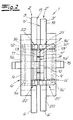
- the flat strip 15 is serpentinely guided around the two housing-fixed axes of rotation 13, 13 '. In the region of the receiving spaces, the flat strip 15 extends between an inner surface of the receiving space and the respective adjacent housing-fixed axis of rotation or longitudinally displaceable axis of rotation.
- the guide helps that the flat strip 15 maintains its defined position during opening and closing movement of the door hinge and can not be kinked or squeezed between parts of the door hinge.
- the mounting flanges 3 ', 4' of the door frame side housing part 2 ' have vertical slots 17, 18 for a height adjustment of the door hinge.
- the vertical slots 17, 18 are penetrated for fixing the door hinge in the recess of the door frame of screws, not shown in the figure, which are screwed into the door frame.
- the height of the door hinge 1 and thus also of the door leaf can be infinitely adjusted when the screws are released.
- the Fig. 1 in that the rear sides 19, 20 of the fastening flanges 3 ', 4' of the frame part 2 'on the side of the door frame are knurled. Due to the knurled backs 19, 20 of the mounting flanges, the attachment of the door hinge in the door frame is basically more stable. This results in an improved protection against sagging of the door hinge due to insufficient fastening of the screws.
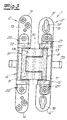
- Fig. 3 it can be seen that the housing part 2 'on the door frame side has a lower and an upper adjustment device 21, 21' for the horizontal adjustment of the Door leaf with respect to the door frame has.
- the connection ends 11', 12 'of the connecting elements 7,8 are mounted.
- the door leaf-side housing part 2 of the illustrated embodiment has, as in Fig. 3 recognizable, a lower and an upper adjusting device 22, 22 'for adjusting the Moserielantikes on. Also at these adjusting devices 22, 22 ', the terminal ends 11, 12 of the connecting elements 7,8 are mounted so that the best possible Moserielantik taking into account the two terminal ends 11, 12 is adjustable.
- the arrangement and guidance of the electrical line according to the invention is particularly suitable for door hinges with small dimensions and correspondingly tight space for the electrical line.
- the housing parts including their mounting flanges have a length of about 140 mm, wherein the receiving spaces are about 90 mm high and 15 mm wide.
- the installation depth is about 23 mm. It is understood that the teaching of the invention is also suitable for door hinges with other dimensions.
Landscapes
- Engineering & Computer Science (AREA)
- Mechanical Engineering (AREA)
- Hinges (AREA)
- Power-Operated Mechanisms For Wings (AREA)
- Electric Cable Arrangement Between Relatively Moving Parts (AREA)
- Casings For Electric Apparatus (AREA)
- Patch Boards (AREA)
Abstract
Description
- Die Erfindung betrifft ein Türband für eine bei geschlossener Tür verdeckte Anordnung zwischen Türzarge und Türflügel mit einer durch das Türband flexibel hindurch geführten Elektroleitung. Zum grundsätzlichen Aufbau des Türbandes gehören zwei Gehäuseteile, die in Ausnehmungen in der Türzarge und im Türflügel einsetzbar sind und einen von einer Rückseite begrenzten Aufnahmeraum für Verbindungselemente aufweisen, und Verbindungselemente, die um eine vertikale Drehachse schwenkbeweglich verbunden sind und Anschlussenden aufweisen, die in den Aufnahmeräumen an den Gehäuseteilen gelagert sind. Ein Anschlussende der Verbindungselemente ist um eine gehäusefeste Drehachse verschwenkbar angeordnet. Das andere Anschlussende der Verbindungselemente ist in dem zugeordneten Aufnahmeraum entlang einer Längsführung, die sich von der Vorderseite der Aufnahmeräume zur Rückseite erstreckt, verschiebbar geführt.
- Ein Türband mit den eingangs beschriebenen Merkmalen ist aus
EP 1 489 255 B1 bekannt. Die Elektroleitung ist durch Bohrungen in Befestigungsflanschen der Gehäuseteile geführt und ermöglicht eine elektrische Stromzuführung von der Türzargenseite zur Türflügelseite, um Stromverbraucher an dem Türblatt möglichst unauffällig durch das Türband mit Strom zu versorgen. In geschlossenem Zustand der Tür ist die Elektroleitung zwar verdeckt und geschützt, doch durch die Öffnungsbewegung der Tür wird die Elektroleitung sichtbar und damit anfällig für fahrlässige oder vorsätzliche Beschädigungen. Insbesondere besteht auch die Gefahr, dass die Elektroleitung beim Öffnen und Schließen der Tür zwischen Teilen des Türbandes gequetscht wird. Eine zusätzlich vorgesehene Schutzleitung soll dies verhindern. Demzufolge sind aufwendige konstruktive Maßnahmen notwendig, um die Elektroleitung zugfrei sicher zu verlegen und zu schützen. - Vor diesem technologischen Hintergrund liegt der Erfindung die Aufgabe zugrunde, die Durchführung der Elektroleitung zu vereinfachen und mit konstruktiv einfachen Mitteln eine ordnungsgemäße Führung der Elektroleitung sicherzustellen. Ferner soll die Elektroleitung beim Öffnen und Schließen der Tür nicht sichtbar sein.
- Die Erfindung wird bei einem Türband mit den eingangs beschriebenen Merkmalen erfindungsgemäß dadurch gelöst, dass die Rückseiten der Aufnahmeräume Durchtrittsöffnungen für die Elektroleitung in Form von Langlöchem aufweisen, welche sich parallel zu der gehäusefesten Drehachse erstrecken, und dass die Elektroleitung aus einem Flachband besteht, welches durch die Langlöcher und das Türband hindurchgeführt ist. Das Flachband ist flexibel und besitzt eine ausreichende Steifigkeit, so dass es die Öffnungs- und Schließbewegungen der Tür ausgleichen kann. Es besteht keine Gefahr, dass das Flachband abknickt oder zwischen Teilen des Türbandes gequetscht wird. Ein Versagen der Stromzuführung durch Kabelbruch des Flachbandes ist dadurch ausgeschlossen. Die erfindungsgemäße Anordnung eignet sich insbesondere auch für Türbänder mit kleinen Abmessungen.
- Das Flachband kann sehr einfach in das Türband eingezogen werden. Da die Gehäuseteile des Türbandes als Metalldruckgussteile hergestellt werden können, bedarf es nur geringer konstruktiver Maßnahmen an den Gussformen, um die Durchtrittsöffnungen an den Rückseiten der Aufnahmeräume der Gehäuseteile anzubringen.
- Vorzugsweise ist das Flachband schlangenförmig um die fest stehenden Drehachsen des Türbandes geführt, wobei das Flachband im Bereich der Aufnahmeräume zwischen einer Innenfläche des Aufnahmeraums und der jeweils benachbarten feststehenden Drehachse oder längs verschiebbaren Drehachse hindurchgeführt ist. Die Führung trägt dazu bei, dass das Flachband bei Öffnungs- und Schließbewegungen des Türbandes seine definierte Lage behält und nicht zwischen Teilen des Türbandes geknickt bzw. gequetscht werden kann. Ein Schutz der Elektroleitung vor Beschädigung ist auf diese Weise auch bei einer Türöffnung um 180° sichergestellt. Hervorzuheben ist ferner, dass die Elektroleitung im Übergangsbereich zwischen Türzarge und Türflügel durch die Verbindungselemente des Türbandes verdeckt ist, da die Durchtrittsöffnungen für die Elektroleitung auf Höhe der Verbindungselemente vorgesehen sind.
- Die Gehäuseteile weisen zweckmäßig einen oberen und einen unteren Befestigungsflansch auf. Die Befestigungsflansche des türzargenseitigen Gehäuseteils können vertikal sich erstreckende Langlöcher für eine Höhenverstellung des Türbandes aufweisen. Die Langlöcher werden von Schrauben durchgriffen, die in die Türzarge eingeschraubt sind. Eine stufenlose Höhenverstellung des Türbandes und damit auch des Türflügels lässt sich durchführen, wenn die Schrauben gelöst sind.
- Vorzugsweise sind die Befestigungsflansche zumindest des türzargenseitigen Gehäuseteils an Ihren Rückseiten gerändelt. Durch die gerändelten Rückseiten der Befestigungsflansche ergibt sich eine verbesserte Absicherung gegen ein Absacken des Türbandes bei unzureichender Befestigung durch nicht ausreichend angezogene Schrauben. Ferner ist die Anordnung des Türbandes in der Türzarge wegen der gerändelten Rückseiten der Befestigungsflansche grundsätzlich stabiler.
- Gemäß einer bevorzugten Ausführung der Erfindung weisen das türzargenseitige oder das türflügelseitige Gehäuseteil eine untere sowie eine obere Verstellvorrichtung zur Horizontalverstellung des Türflügels in Bezug auf die Türzarge auf. An den beiden Verstellvorrichtungen sind die Anschlussenden der Verbindungselemente gelagert, so dass eine optimale Einstellung des Türflügels in Breitenrichtung der Tür unter Berücksichtigung des um die gehäusefeste Drehachse angeordneten Anschlussendes sowie des in der Längsführung verschiebbaren Anschlussendes möglich ist.
- In einer weiteren bevorzugten Ausführung der Erfindung weist das türzargenseitige oder das türflügelseitige Gehäuseteil eine untere sowie eine obere Verstellvorrichtung zur Verstellung des Türflügelandruckes auf. Auch an diesen Verstelleinrichtungen sind die Anschlussenden der Verbindungselemente gelagert. Der Türflügelandruck ist dadurch ebenfalls bestmöglich unter Berücksichtigung der jeweiligen Position der Anschlussenden einstellbar. Durch die Verstellmöglichkeiten für die vertikale bzw. horizontale Position des Türflügels ergibt sich insgesamt zusammen mit der Verstellmöglichkeit für den Türflügelandruck eine dreidimensionale Verstellbarkeit des erfindungsgemäßen Türbandes.
- Im Folgenden wird die Erfindung anhand einer lediglich ein Ausführungsbeispiel darstellenden Zeichnung erläutert. Es zeigen schematisch:
- Fig. 1
- eine Rückansicht des Türbandes bei einer Türöffnung um 180°,
- Fig. 2
- das erfindungsgemäße Türband in einer Seitenansicht, und zwar für die Funktionsstellung "geschlossene Tür",
- Fig. 3
- eine Vorderansicht des Türbandes bei einer Türöffnung um 180°.
- Die Figuren zeigen ein Türband 1 für eine bei geschlossener Tür verdeckte Anordnung zwischen Türzarge und Türflügel. Das Türband weist zwei Gehäuseteile 2, 2' auf, die in Ausnehmungen in der Türzarge und im Türflügel einsetzbar sind. Die Gehäuseteile 2, 2' umfassen einen oberen und einen unteren Befestigungsflansch 3, 4; 3', 4' mit einer jeweils bündig mit der Türzarge bzw. dem Türflügel abschließenden Vorderseite 5, 5', sowie einen Aufnahmeraum 6, 6' für Verbindungselemente 7, 8. Die Aufnahmeräume weisen eine in die Ausnehmung einsetzbare Rückseite 9, 9' auf. Das Türband 1 besitzt ferner Verbindungselemente 7, 8, die um eine vertikale Drehachse 10 schwenkbeweglich verbunden sind und Anschlussenden 11, 12; 11', 12' aufweisen, die in den Aufnahmeräumen 6, 6' an den Gehäuseteilen 2, 2' gelagert sind. Während ein Anschlussende 11, 11' der Verbindungselemente um eine gehäusefeste Drehachse 13, 13' verschwenkbar angeordnet ist, ist das andere Anschlussende 12, 12' der Verbindungselemente 7, 8 in dem zugeordneten Aufnahmeraum 6, 6' entlang einer Längsführung 14, 14' verschiebbar geführt, die sich von der Vorderseite der Aufnahmeräume 6, 6' zur Rückseite erstreckt. Des Weiteren ist eine durch das Türband flexibel hindurch geführte Elektroleitung vorgesehen, die als Flachband 15 ausgebildet ist. Wie insbesondere
Fig. 1 zu entnehmen ist, weisen die Rückseiten 9, 9' der Aufnahmeräume 6, 6' Durchtrittsöffnungen für das Flachband 15 auf, die als Langlöcher 16, 16' ausgebildet sind und sich in Höhe der Verbindungselemente 7, 8 vertikal bzw. parallel zu der gehäusefesten Drehachse 13, 13' erstrecken. - Das Flachband 15 ist flexibel und dergestalt durch das Türband geführt, dass ein Einklemmen, Einquetschen oder Abknicken des Flachbandes durch Teile des Türbandes nicht möglich ist. Das durch die Gehäuseteile 2, 2' geführte Flachband ist bei geöffneter Tür durch die Verbindungselemente 7, 8 verdeckt und dadurch vor fahrlässiger oder vorsätzlicher Beschädigung geschützt. Die Gehäuseteile 2, 2' des dargestellten Ausführungsbeispiels können als Metalldruckgussteile, z. B. Zinkdruckgussteile, hergestellt werden. Es sind nur geringe konstruktive Maßnahmen an den Gussformen für die Gehäuseteile 2, 2' notwendig, um die Durchtrittsöffnungen 16, 16' an der Rückseite 9, 9' des jeweiligen Aufnahmeraumes 6, 6' anzubringen.
- Aus
Fig. 2 ist ersichtlich, dass das Flachband 15 schlangenförmig um die beiden gehäusefesten Drehachsen 13, 13' geführt ist. Im Bereich der Aufnahmeräume verläuft das Flachband 15 zwischen einer Innenfläche des Aufnahmeraums und der jeweils benachbarten gehäusefesten Drehachse oder längsverschiebbaren Drehachse. Die Führung trägt dazu bei, dass das Flachband 15 bei Öffnungs- und Schließbewegung des Türbandes seine definierte Lage beibehält und nicht zwischen Teilen des Türbandes geknickt bzw. gequetscht werden kann. - In der in
Fig. 3 dargestellten Funktionsstellung "geöffnete Tür" ist das Flachband durch die Verbindungselemente 7, 8 verdeckt und folglich in einer Ansicht auf das Türband nicht sichtbar. Durch die verdeckte Anordnung ist das Flachband 15 auch vor fahrlässiger oder vorsätzlicher Beschädigung geschützt. -
Fig. 3 ist zu entnehmen, dass die Befestigungsflansche 3', 4' des türzargenseitigen Gehäuseteils 2' vertikale Langlöcher 17, 18 für eine Höhenverstellung des Türbandes aufweisen. Die vertikalen Langlöcher 17, 18 werden zur Befestigung des Türbandes in der Ausnehmung der Türzarge von in der Figur nicht dargestellten Schrauben durchgriffen, die in die Türzarge eingeschraubt sind. Die Höhe des Türbandes 1 und damit auch des Türflügels lässt sich stufenlos verstellen, wenn die Schrauben gelöst sind. Des Weiteren entnimmt man derFig. 1 , dass die Rückseiten 19, 20 der Befestigungsflansche 3', 4' des türzargenseitigen Gehäuseteils 2' gerändelt sind. Durch die gerändelten Rückseiten 19, 20 der Befestigungsflansche ist die Anbringung des Türbandes in der Türzarge grundsätzlich stabiler. Es ergibt sich eine verbesserte Absicherung gegen ein Absacken des Türbandes infolge von unzureichender Befestigung der Schrauben. - Ferner ist aus
Fig. 3 ersichtlich, dass das türzargenseitige Gehäuseteil 2' eine untere und eine obere Verstellvorrichtung 21, 21' zur Horizontalverstellung des Türflügels in Bezug auf die Türzarge aufweist. An den Verstellvorrichtungen 21, 21' sind die Anschlussenden 11', 12' der Verbindungselemente 7,8 gelagert. Durch diese konstruktive Maßnahme ist eine optimale Einstellung des Türflügels in Breitenrichtung der Tür möglich, da sowohl das um die gehäusefeste Drehachse 13' angeordnete Anschlussende 11' als auch das in der Längsführung 14' verschiebbare Anschlussende 12' berücksichtigt sind. - Das türflügelseitige Gehäuseteil 2 des dargestellten Ausführungsbeispiels weist, wie in
Fig. 3 erkennbar, eine untere und eine obere Verstellvorrichtung 22, 22' zur Verstellung des Türflügelandruckes auf. Auch an diesen Verstelleinrichtungen 22, 22' sind die Anschlussenden 11, 12 der Verbindungselemente 7,8 gelagert, so dass ein bestmöglicher Türflügelandruck unter Berücksichtigung der beiden Anschlussenden 11, 12 einstellbar ist. - Die erfindungsgemäße Anordnung und Führung der Elektroleitung eignet sich insbesondere auch für Türbänder mit kleinen Abmessungen und entsprechend engen Platzverhältnissen für die Elektroleitung. Im Ausführungsbeispiel weisen die Gehäuseteile einschließlich ihrer Befestigungsflansche eine Länge von ca. 140 mm auf, wobei die Aufnahmeräume etwa 90 mm hoch und 15 mm breit sind. Die Einbautiefe beträgt etwa 23 mm. Es versteht sich, dass die erfindungsgemäße Lehre auch für Türbänder mit anderen Abmessungen geeignet ist.
Claims (6)
- Türband für eine bei geschlossener Tür verdeckte Anordnung zwischen Türzarge und Türflügel, mit
zwei Gehäuseteilen (2, 2'), die in Ausnehmungen in der Türzarge und im Türflügel einsetzbar sind sowie einen von einer Rückseite (9, 9') begrenzten Aufnahmeraum für Verbindungselemente (7, 8) aufweisen, und
Verbindungselementen (7, 8), die um eine vertikale Drehachse (10) schwenkbeweglich verbunden sind und Anschlussenden (11, 12; 11', 12') aufweisen, die in den Aufnahmeräumen (6, 6') an den Gehäuseteilen (2, 2') gelagert sind,
wobei ein Anschlussende (11, 11') der Verbindungselemente (7, 8) um eine gehäusefeste Drehachse (13, 13') verschwenkbar angeordnet ist und das andere Anschlussende (12, 12') der Verbindungselemente (7, 8) in dem zugeordneten Aufnahmeraum (6, 6') entlang einer Längsführung (14, 14'), die sich von der Vorderseite der Aufnahmeräume (6, 6') zur Rückseite (9, 9') erstreckt, verschiebbar geführt ist, und wobei eine durch das Türband flexibel hindurchgeführte Elektroleitung vorgesehen ist, dadurch gekennzeichnet, dass die Rückseiten (9, 9') der Aufnahmeräume (6, 6') Durchtrittsöffnungen für die Elektroleitung in Form von Langlöchern (16, 16') aufweisen, welche sich parallel zu der gehäusefesten Drehachse (13, 13') erstrecken, und dass die Elektroleitung aus einem Flachband (15) besteht, welches durch die Langlöcher (16, 16') und das Türband hindurchgeführt ist. - Türband nach Anspruch 1, dadurch gekennzeichnet, dass das Flachband (15) schlangenförmig um die beiden gehäusefesten Drehachsen (13, 13') geführt ist.
- Türband nach Anspruch 1 oder 2, dadurch gekennzeichnet, dass die Gehäuseteile (2, 2') einen oberen und einen unteren Befestigungsflansch (3, 4; 3', 4') aufweisen und dass die Befestigungsflansche (3', 4') des türzargenseitigen Gehäuseteils Langlöcher (17, 18) für eine Höhenverstellung des Türbandes aufweisen.
- Türband nach Anspruch 3, dadurch gekennzeichnet, dass die Befestigungsflansche (3', 4') zumindest des türzargenseitigen Gehäuseteils (2') an ihren Rückseiten (19, 20) gerändelt sind.
- Türband nach einem der Ansprüche 1 bis 4, dadurch gekennzeichnet, dass das türzargenseitige oder das türflügelseitige Gehäuseteil (2, 2') eine untere sowie eine obere Verstellvorrichtung (21, 21') zur Horizontalverstellung des Türflügels in Bezug auf die Türzarge aufweist.
- Türband nach einem der Ansprüche 1 bis 5, dadurch gekennzeichnet, dass das türzargenseitige oder das türflügelseitige Gehäuseteil (2, 2') eine untere und eine obere Verstellvorrichtung (22, 22') zur Verstellung des Türflügelandruckes aufweist.
Priority Applications (1)
| Application Number | Priority Date | Filing Date | Title |
|---|---|---|---|
| PL08013429T PL2031166T3 (pl) | 2007-09-03 | 2008-07-25 | Zawias drzwiowy z przewodem elektrycznym |
Applications Claiming Priority (1)
| Application Number | Priority Date | Filing Date | Title |
|---|---|---|---|
| DE102007041816A DE102007041816B4 (de) | 2007-09-03 | 2007-09-03 | Türband mit Elektroleitung |
Publications (3)
| Publication Number | Publication Date |
|---|---|
| EP2031166A2 true EP2031166A2 (de) | 2009-03-04 |
| EP2031166A3 EP2031166A3 (de) | 2012-09-12 |
| EP2031166B1 EP2031166B1 (de) | 2013-12-11 |
Family
ID=39985963
Family Applications (1)
| Application Number | Title | Priority Date | Filing Date |
|---|---|---|---|
| EP08013429.9A Active EP2031166B1 (de) | 2007-09-03 | 2008-07-25 | Türband mit Elektroleitung |
Country Status (4)
| Country | Link |
|---|---|
| EP (1) | EP2031166B1 (de) |
| DE (1) | DE102007041816B4 (de) |
| ES (1) | ES2449104T3 (de) |
| PL (1) | PL2031166T3 (de) |
Cited By (1)
| Publication number | Priority date | Publication date | Assignee | Title |
|---|---|---|---|---|
| WO2023161301A1 (en) * | 2022-02-23 | 2023-08-31 | Arrival Uk Ltd | A hinge and a joining method |
Families Citing this family (7)
| Publication number | Priority date | Publication date | Assignee | Title |
|---|---|---|---|---|
| DE102012101644B3 (de) * | 2012-02-29 | 2012-10-18 | Simonswerk, Gesellschaft mit beschränkter Haftung | Türband für eine verdeckte Anordnung zwischen Türzarge und Türflügel |
| DE102013108083B3 (de) * | 2013-07-29 | 2014-05-15 | Simonswerk, Gesellschaft mit beschränkter Haftung | Verdeckt liegendes Türband mit elektrischer Verbindung |
| DE102013108973B3 (de) * | 2013-08-20 | 2014-09-11 | Simonswerk, Gesellschaft mit beschränkter Haftung | Scharnier sowie Türanordnung |
| ES2737832T3 (es) | 2015-10-12 | 2020-01-16 | Kuantica S R L | Bisagra escondida invisible para puertas |
| EP3362624B1 (de) | 2015-10-12 | 2019-08-21 | Kuantica S.r.l. | Unsichtbares verborgenes scharnier für türen mit positionsregulierung |
| DE102016123578B3 (de) * | 2016-12-06 | 2017-09-07 | Simonswerk Gmbh | Scharnier sowie Türanordnung |
| CH715484B1 (de) | 2018-10-18 | 2023-09-29 | Sitter Christian | Scharnier mit einer Kabeldurchführung sowie ein Verfahren zum Montieren bzw. Demontieren des Scharniers. |
Citations (1)
| Publication number | Priority date | Publication date | Assignee | Title |
|---|---|---|---|---|
| EP1489255B1 (de) | 2003-06-21 | 2007-02-28 | Simonswerk GmbH | Türband für eine bei geschlossener Tür verdeckte Anordnung zwischen Türzarge und Türflügel mit einer Durchgangbohrung für eine Elektroleitung |
Family Cites Families (7)
| Publication number | Priority date | Publication date | Assignee | Title |
|---|---|---|---|---|
| JPH0411856Y2 (de) * | 1984-11-02 | 1992-03-24 | ||
| FR2664438B1 (fr) * | 1990-07-04 | 1994-07-22 | Alcatel Radiotelephone | Dispositif forme de deux elements articules autour d'une charniere et relies par une liaison electrique. |
| FI100038B (fi) * | 1995-12-22 | 1997-08-29 | Nokia Mobile Phones Ltd | Saranoitu laite |
| KR100399309B1 (ko) * | 2000-11-30 | 2003-10-08 | 태 선 김 | 전자 도어용 힌지 |
| US7063042B2 (en) * | 2003-10-31 | 2006-06-20 | C. Hager & Sons Hinge Manufacturing Co. | Continuous gear hinge with electrical conductor |
| FR2878379B1 (fr) * | 2004-11-19 | 2008-04-04 | Airbus France Sas | Armoire electrique avec connexion electrique a sa porte |
| DE102005051918B4 (de) * | 2005-10-29 | 2013-12-05 | Bartels Systembeschläge GmbH | Türband für den verdeckten Einbau zur drehbeweglichen Verbindung eines Türflügels an einer Türzarge |
-
2007
- 2007-09-03 DE DE102007041816A patent/DE102007041816B4/de active Active
-
2008
- 2008-07-25 PL PL08013429T patent/PL2031166T3/pl unknown
- 2008-07-25 ES ES08013429.9T patent/ES2449104T3/es active Active
- 2008-07-25 EP EP08013429.9A patent/EP2031166B1/de active Active
Patent Citations (1)
| Publication number | Priority date | Publication date | Assignee | Title |
|---|---|---|---|---|
| EP1489255B1 (de) | 2003-06-21 | 2007-02-28 | Simonswerk GmbH | Türband für eine bei geschlossener Tür verdeckte Anordnung zwischen Türzarge und Türflügel mit einer Durchgangbohrung für eine Elektroleitung |
Cited By (1)
| Publication number | Priority date | Publication date | Assignee | Title |
|---|---|---|---|---|
| WO2023161301A1 (en) * | 2022-02-23 | 2023-08-31 | Arrival Uk Ltd | A hinge and a joining method |
Also Published As
| Publication number | Publication date |
|---|---|
| DE102007041816B4 (de) | 2009-08-27 |
| DE102007041816A1 (de) | 2009-03-05 |
| EP2031166B1 (de) | 2013-12-11 |
| PL2031166T3 (pl) | 2014-05-30 |
| EP2031166A3 (de) | 2012-09-12 |
| ES2449104T3 (es) | 2014-03-18 |
Similar Documents
| Publication | Publication Date | Title |
|---|---|---|
| EP2031166B1 (de) | Türband mit Elektroleitung | |
| DE102011000150B3 (de) | Türband für eine verdeckte Anordnung zwischen Türrahmen und Türflügel | |
| DE10319826B4 (de) | Schutzführung für ein ein- und ausziehbares Kabel o. dgl. | |
| EP2476836A1 (de) | Türband | |
| DE10253401A1 (de) | Schiebedachsystem für ein Kraftfahrzeug | |
| EP2163717B1 (de) | Vorrichtung zur Anordnung eines Gehäuses an einem Flügel und Verfahren zur Montage | |
| DE102013108973B3 (de) | Scharnier sowie Türanordnung | |
| WO2012076252A1 (de) | Anordnung zur kabelführung | |
| EP1489255B1 (de) | Türband für eine bei geschlossener Tür verdeckte Anordnung zwischen Türzarge und Türflügel mit einer Durchgangbohrung für eine Elektroleitung | |
| EP3333345B1 (de) | Scharnier sowie türanordnung | |
| DE202013103531U1 (de) | Schiebetür sowie Möbelstück | |
| EP2192665B1 (de) | Bodeneinbaukassette für elektrische Installationsgeräte | |
| DE202019101645U1 (de) | Scharnierband für Türen, Fenster und Möbel | |
| DE102010022700B3 (de) | Vorrichtung und Verfahren zur Herstellung einer elektrischen Verbindung zwischen zwei durch ein Scharnier verbundenen Bauteilen | |
| DE202004019742U1 (de) | Band für eine verdeckte Anordnung zwischen Zarge und Flügel | |
| EP2616618A1 (de) | Anordnung zur kabelführung | |
| EP1617102A2 (de) | Kette für eine Schwenkeinrichtung zum Schließen und Öffnen von Klappen, Türen, Fenstern oder dergleichen | |
| DE102012108916A1 (de) | Liegender Schaltschrank mit Schwenkrahmen | |
| EP2113630B1 (de) | Gurtwickler für eine Verdunkelungsvorrichtung wie einen Rolladen o. dgl. | |
| DE102005021841B4 (de) | Befestigunsvorrichtung von Schaltgeräten auf Tragschiene | |
| DE202005019103U1 (de) | Kabelführungsgruppe sowie Schiebetür für Kraftfahrzeuge | |
| EP3783178B1 (de) | Tür | |
| DE102017207981B4 (de) | Kabelbrückenvorrichtung und Kabelbrückenanordnung | |
| DE3912727C1 (en) | Electrical switch cabinet for measuring and/or display device(s) - has front mounting frame for switch appts. module, and front access door | |
| DE8109470U1 (de) | "Schaltplantasche für einen Schaltschrank" |
Legal Events
| Date | Code | Title | Description |
|---|---|---|---|
| PUAI | Public reference made under article 153(3) epc to a published international application that has entered the european phase |
Free format text: ORIGINAL CODE: 0009012 |
|
| AK | Designated contracting states |
Kind code of ref document: A2 Designated state(s): AT BE BG CH CY CZ DE DK EE ES FI FR GB GR HR HU IE IS IT LI LT LU LV MC MT NL NO PL PT RO SE SI SK TR |
|
| AX | Request for extension of the european patent |
Extension state: AL BA MK RS |
|
| PUAL | Search report despatched |
Free format text: ORIGINAL CODE: 0009013 |
|
| AK | Designated contracting states |
Kind code of ref document: A3 Designated state(s): AT BE BG CH CY CZ DE DK EE ES FI FR GB GR HR HU IE IS IT LI LT LU LV MC MT NL NO PL PT RO SE SI SK TR |
|
| AX | Request for extension of the european patent |
Extension state: AL BA MK RS |
|
| RIC1 | Information provided on ipc code assigned before grant |
Ipc: E05D 11/00 20060101AFI20120809BHEP Ipc: E05D 3/18 20060101ALI20120809BHEP |
|
| 17P | Request for examination filed |
Effective date: 20130312 |
|
| AKX | Designation fees paid |
Designated state(s): AT BE BG CH CY CZ DE DK EE ES FI FR GB GR HR HU IE IS IT LI LT LU LV MC MT NL NO PL PT RO SE SI SK TR |
|
| GRAP | Despatch of communication of intention to grant a patent |
Free format text: ORIGINAL CODE: EPIDOSNIGR1 |
|
| INTG | Intention to grant announced |
Effective date: 20130703 |
|
| GRAS | Grant fee paid |
Free format text: ORIGINAL CODE: EPIDOSNIGR3 |
|
| GRAA | (expected) grant |
Free format text: ORIGINAL CODE: 0009210 |
|
| AK | Designated contracting states |
Kind code of ref document: B1 Designated state(s): AT BE BG CH CY CZ DE DK EE ES FI FR GB GR HR HU IE IS IT LI LT LU LV MC MT NL NO PL PT RO SE SI SK TR |
|
| REG | Reference to a national code |
Ref country code: GB Ref legal event code: FG4D Free format text: NOT ENGLISH |
|
| REG | Reference to a national code |
Ref country code: CH Ref legal event code: EP |
|
| REG | Reference to a national code |
Ref country code: AT Ref legal event code: REF Ref document number: 644712 Country of ref document: AT Kind code of ref document: T Effective date: 20140115 |
|
| REG | Reference to a national code |
Ref country code: IE Ref legal event code: FG4D Free format text: LANGUAGE OF EP DOCUMENT: GERMAN |
|
| REG | Reference to a national code |
Ref country code: DE Ref legal event code: R096 Ref document number: 502008011042 Country of ref document: DE Effective date: 20140206 |
|
| REG | Reference to a national code |
Ref country code: NL Ref legal event code: T3 |
|
| REG | Reference to a national code |
Ref country code: SE Ref legal event code: TRGR Ref country code: ES Ref legal event code: FG2A Ref document number: 2449104 Country of ref document: ES Kind code of ref document: T3 Effective date: 20140318 |
|
| REG | Reference to a national code |
Ref country code: CH Ref legal event code: NV Representative=s name: KELLER AND PARTNER PATENTANWAELTE AG, CH |
|
| PG25 | Lapsed in a contracting state [announced via postgrant information from national office to epo] |
Ref country code: HR Free format text: LAPSE BECAUSE OF FAILURE TO SUBMIT A TRANSLATION OF THE DESCRIPTION OR TO PAY THE FEE WITHIN THE PRESCRIBED TIME-LIMIT Effective date: 20131211 Ref country code: LT Free format text: LAPSE BECAUSE OF FAILURE TO SUBMIT A TRANSLATION OF THE DESCRIPTION OR TO PAY THE FEE WITHIN THE PRESCRIBED TIME-LIMIT Effective date: 20131211 Ref country code: FI Free format text: LAPSE BECAUSE OF FAILURE TO SUBMIT A TRANSLATION OF THE DESCRIPTION OR TO PAY THE FEE WITHIN THE PRESCRIBED TIME-LIMIT Effective date: 20131211 Ref country code: NO Free format text: LAPSE BECAUSE OF FAILURE TO SUBMIT A TRANSLATION OF THE DESCRIPTION OR TO PAY THE FEE WITHIN THE PRESCRIBED TIME-LIMIT Effective date: 20140311 |
|
| REG | Reference to a national code |
Ref country code: LT Ref legal event code: MG4D |
|
| PG25 | Lapsed in a contracting state [announced via postgrant information from national office to epo] |
Ref country code: LV Free format text: LAPSE BECAUSE OF FAILURE TO SUBMIT A TRANSLATION OF THE DESCRIPTION OR TO PAY THE FEE WITHIN THE PRESCRIBED TIME-LIMIT Effective date: 20131211 Ref country code: CY Free format text: LAPSE BECAUSE OF FAILURE TO SUBMIT A TRANSLATION OF THE DESCRIPTION OR TO PAY THE FEE WITHIN THE PRESCRIBED TIME-LIMIT Effective date: 20131211 |
|
| REG | Reference to a national code |
Ref country code: PL Ref legal event code: T3 |
|
| PG25 | Lapsed in a contracting state [announced via postgrant information from national office to epo] |
Ref country code: IS Free format text: LAPSE BECAUSE OF FAILURE TO SUBMIT A TRANSLATION OF THE DESCRIPTION OR TO PAY THE FEE WITHIN THE PRESCRIBED TIME-LIMIT Effective date: 20140411 Ref country code: EE Free format text: LAPSE BECAUSE OF FAILURE TO SUBMIT A TRANSLATION OF THE DESCRIPTION OR TO PAY THE FEE WITHIN THE PRESCRIBED TIME-LIMIT Effective date: 20131211 |
|
| PG25 | Lapsed in a contracting state [announced via postgrant information from national office to epo] |
Ref country code: PT Free format text: LAPSE BECAUSE OF FAILURE TO SUBMIT A TRANSLATION OF THE DESCRIPTION OR TO PAY THE FEE WITHIN THE PRESCRIBED TIME-LIMIT Effective date: 20140411 Ref country code: RO Free format text: LAPSE BECAUSE OF FAILURE TO SUBMIT A TRANSLATION OF THE DESCRIPTION OR TO PAY THE FEE WITHIN THE PRESCRIBED TIME-LIMIT Effective date: 20131211 Ref country code: SK Free format text: LAPSE BECAUSE OF FAILURE TO SUBMIT A TRANSLATION OF THE DESCRIPTION OR TO PAY THE FEE WITHIN THE PRESCRIBED TIME-LIMIT Effective date: 20131211 |
|
| REG | Reference to a national code |
Ref country code: DE Ref legal event code: R097 Ref document number: 502008011042 Country of ref document: DE |
|
| PLBE | No opposition filed within time limit |
Free format text: ORIGINAL CODE: 0009261 |
|
| STAA | Information on the status of an ep patent application or granted ep patent |
Free format text: STATUS: NO OPPOSITION FILED WITHIN TIME LIMIT |
|
| PG25 | Lapsed in a contracting state [announced via postgrant information from national office to epo] |
Ref country code: DK Free format text: LAPSE BECAUSE OF FAILURE TO SUBMIT A TRANSLATION OF THE DESCRIPTION OR TO PAY THE FEE WITHIN THE PRESCRIBED TIME-LIMIT Effective date: 20131211 |
|
| 26N | No opposition filed |
Effective date: 20140912 |
|
| REG | Reference to a national code |
Ref country code: DE Ref legal event code: R097 Ref document number: 502008011042 Country of ref document: DE Effective date: 20140912 |
|
| PG25 | Lapsed in a contracting state [announced via postgrant information from national office to epo] |
Ref country code: SI Free format text: LAPSE BECAUSE OF FAILURE TO SUBMIT A TRANSLATION OF THE DESCRIPTION OR TO PAY THE FEE WITHIN THE PRESCRIBED TIME-LIMIT Effective date: 20131211 Ref country code: LU Free format text: LAPSE BECAUSE OF FAILURE TO SUBMIT A TRANSLATION OF THE DESCRIPTION OR TO PAY THE FEE WITHIN THE PRESCRIBED TIME-LIMIT Effective date: 20140725 |
|
| REG | Reference to a national code |
Ref country code: CH Ref legal event code: PCAR Free format text: NEW ADDRESS: EIGERSTRASSE 2 POSTFACH, 3000 BERN 14 (CH) |
|
| REG | Reference to a national code |
Ref country code: IE Ref legal event code: MM4A |
|
| PG25 | Lapsed in a contracting state [announced via postgrant information from national office to epo] |
Ref country code: IE Free format text: LAPSE BECAUSE OF NON-PAYMENT OF DUE FEES Effective date: 20140725 |
|
| PG25 | Lapsed in a contracting state [announced via postgrant information from national office to epo] |
Ref country code: MC Free format text: LAPSE BECAUSE OF FAILURE TO SUBMIT A TRANSLATION OF THE DESCRIPTION OR TO PAY THE FEE WITHIN THE PRESCRIBED TIME-LIMIT Effective date: 20131211 |
|
| PG25 | Lapsed in a contracting state [announced via postgrant information from national office to epo] |
Ref country code: BG Free format text: LAPSE BECAUSE OF FAILURE TO SUBMIT A TRANSLATION OF THE DESCRIPTION OR TO PAY THE FEE WITHIN THE PRESCRIBED TIME-LIMIT Effective date: 20131211 |
|
| PG25 | Lapsed in a contracting state [announced via postgrant information from national office to epo] |
Ref country code: MT Free format text: LAPSE BECAUSE OF FAILURE TO SUBMIT A TRANSLATION OF THE DESCRIPTION OR TO PAY THE FEE WITHIN THE PRESCRIBED TIME-LIMIT Effective date: 20131211 Ref country code: GR Free format text: LAPSE BECAUSE OF FAILURE TO SUBMIT A TRANSLATION OF THE DESCRIPTION OR TO PAY THE FEE WITHIN THE PRESCRIBED TIME-LIMIT Effective date: 20140312 |
|
| REG | Reference to a national code |
Ref country code: FR Ref legal event code: PLFP Year of fee payment: 9 |
|
| PG25 | Lapsed in a contracting state [announced via postgrant information from national office to epo] |
Ref country code: HU Free format text: LAPSE BECAUSE OF FAILURE TO SUBMIT A TRANSLATION OF THE DESCRIPTION OR TO PAY THE FEE WITHIN THE PRESCRIBED TIME-LIMIT; INVALID AB INITIO Effective date: 20080725 |
|
| REG | Reference to a national code |
Ref country code: FR Ref legal event code: PLFP Year of fee payment: 10 |
|
| REG | Reference to a national code |
Ref country code: FR Ref legal event code: PLFP Year of fee payment: 11 |
|
| PGFP | Annual fee paid to national office [announced via postgrant information from national office to epo] |
Ref country code: DK Payment date: 20180723 Year of fee payment: 11 Ref country code: SE Payment date: 20180719 Year of fee payment: 11 |
|
| REG | Reference to a national code |
Ref country code: SE Ref legal event code: EUG |
|
| PG25 | Lapsed in a contracting state [announced via postgrant information from national office to epo] |
Ref country code: SE Free format text: LAPSE BECAUSE OF NON-PAYMENT OF DUE FEES Effective date: 20190726 |
|
| REG | Reference to a national code |
Ref country code: CH Ref legal event code: PFA Owner name: SIMONSWERK, GESELLSCHAFT MIT BESCHRAENKTER HAF, DE Free format text: FORMER OWNER: SIMONSWERK, GESELLSCHAFT MIT BESCHRAENKTER HAFTUNG, DE |
|
| PGFP | Annual fee paid to national office [announced via postgrant information from national office to epo] |
Ref country code: NL Payment date: 20210721 Year of fee payment: 14 |
|
| PGFP | Annual fee paid to national office [announced via postgrant information from national office to epo] |
Ref country code: AT Payment date: 20210722 Year of fee payment: 14 Ref country code: CZ Payment date: 20210726 Year of fee payment: 14 Ref country code: FR Payment date: 20210728 Year of fee payment: 14 Ref country code: IT Payment date: 20210727 Year of fee payment: 14 |
|
| PGFP | Annual fee paid to national office [announced via postgrant information from national office to epo] |
Ref country code: ES Payment date: 20210927 Year of fee payment: 14 Ref country code: GB Payment date: 20210722 Year of fee payment: 14 Ref country code: CH Payment date: 20210721 Year of fee payment: 14 Ref country code: BE Payment date: 20210721 Year of fee payment: 14 Ref country code: PL Payment date: 20210716 Year of fee payment: 14 |
|
| PG25 | Lapsed in a contracting state [announced via postgrant information from national office to epo] |
Ref country code: TR Free format text: LAPSE BECAUSE OF NON-PAYMENT OF DUE FEES Effective date: 20190725 |
|
| REG | Reference to a national code |
Ref country code: CH Ref legal event code: PL |
|
| REG | Reference to a national code |
Ref country code: NL Ref legal event code: MM Effective date: 20220801 |
|
| REG | Reference to a national code |
Ref country code: AT Ref legal event code: MM01 Ref document number: 644712 Country of ref document: AT Kind code of ref document: T Effective date: 20220725 |
|
| GBPC | Gb: european patent ceased through non-payment of renewal fee |
Effective date: 20220725 |
|
| REG | Reference to a national code |
Ref country code: BE Ref legal event code: MM Effective date: 20220731 |
|
| PG25 | Lapsed in a contracting state [announced via postgrant information from national office to epo] |
Ref country code: LI Free format text: LAPSE BECAUSE OF NON-PAYMENT OF DUE FEES Effective date: 20220731 Ref country code: FR Free format text: LAPSE BECAUSE OF NON-PAYMENT OF DUE FEES Effective date: 20220731 Ref country code: CZ Free format text: LAPSE BECAUSE OF NON-PAYMENT OF DUE FEES Effective date: 20220725 Ref country code: CH Free format text: LAPSE BECAUSE OF NON-PAYMENT OF DUE FEES Effective date: 20220731 Ref country code: AT Free format text: LAPSE BECAUSE OF NON-PAYMENT OF DUE FEES Effective date: 20220725 |
|
| PG25 | Lapsed in a contracting state [announced via postgrant information from national office to epo] |
Ref country code: GB Free format text: LAPSE BECAUSE OF NON-PAYMENT OF DUE FEES Effective date: 20220725 Ref country code: BE Free format text: LAPSE BECAUSE OF NON-PAYMENT OF DUE FEES Effective date: 20220731 |
|
| PG25 | Lapsed in a contracting state [announced via postgrant information from national office to epo] |
Ref country code: NL Free format text: LAPSE BECAUSE OF NON-PAYMENT OF DUE FEES Effective date: 20220801 |
|
| PG25 | Lapsed in a contracting state [announced via postgrant information from national office to epo] |
Ref country code: IT Free format text: LAPSE BECAUSE OF NON-PAYMENT OF DUE FEES Effective date: 20220725 |
|
| REG | Reference to a national code |
Ref country code: ES Ref legal event code: FD2A Effective date: 20230901 |
|
| PG25 | Lapsed in a contracting state [announced via postgrant information from national office to epo] |
Ref country code: ES Free format text: LAPSE BECAUSE OF NON-PAYMENT OF DUE FEES Effective date: 20220726 |
|
| PG25 | Lapsed in a contracting state [announced via postgrant information from national office to epo] |
Ref country code: PL Free format text: LAPSE BECAUSE OF NON-PAYMENT OF DUE FEES Effective date: 20220725 |
|
| PGFP | Annual fee paid to national office [announced via postgrant information from national office to epo] |
Ref country code: DE Payment date: 20230615 Year of fee payment: 16 |