EP2028845A2 - Vorrichtung und Verfahren zur Bildaufnahmesteuerung - Google Patents
Vorrichtung und Verfahren zur Bildaufnahmesteuerung Download PDFInfo
- Publication number
- EP2028845A2 EP2028845A2 EP08161964A EP08161964A EP2028845A2 EP 2028845 A2 EP2028845 A2 EP 2028845A2 EP 08161964 A EP08161964 A EP 08161964A EP 08161964 A EP08161964 A EP 08161964A EP 2028845 A2 EP2028845 A2 EP 2028845A2
- Authority
- EP
- European Patent Office
- Prior art keywords
- image
- light
- illumination
- image pickup
- wavelength
- Prior art date
- Legal status (The legal status is an assumption and is not a legal conclusion. Google has not performed a legal analysis and makes no representation as to the accuracy of the status listed.)
- Withdrawn
Links
- 238000000034 method Methods 0.000 title claims description 8
- 238000005286 illumination Methods 0.000 claims abstract description 207
- 230000001360 synchronised effect Effects 0.000 claims abstract description 17
- 230000001678 irradiating effect Effects 0.000 claims description 5
- 230000003287 optical effect Effects 0.000 abstract description 20
- 230000011514 reflex Effects 0.000 abstract description 16
- 238000012806 monitoring device Methods 0.000 abstract description 2
- 238000012545 processing Methods 0.000 description 59
- 238000001228 spectrum Methods 0.000 description 28
- 238000012544 monitoring process Methods 0.000 description 15
- 230000005540 biological transmission Effects 0.000 description 9
- 230000010287 polarization Effects 0.000 description 9
- 230000007423 decrease Effects 0.000 description 8
- 238000010586 diagram Methods 0.000 description 8
- 238000002834 transmittance Methods 0.000 description 6
- 230000008859 change Effects 0.000 description 4
- 230000006870 function Effects 0.000 description 4
- 230000005855 radiation Effects 0.000 description 4
- 230000002829 reductive effect Effects 0.000 description 4
- 230000000295 complement effect Effects 0.000 description 3
- 238000001514 detection method Methods 0.000 description 3
- QSHDDOUJBYECFT-UHFFFAOYSA-N mercury Chemical compound [Hg] QSHDDOUJBYECFT-UHFFFAOYSA-N 0.000 description 3
- 229910044991 metal oxide Inorganic materials 0.000 description 3
- 150000004706 metal oxides Chemical class 0.000 description 3
- 230000003595 spectral effect Effects 0.000 description 3
- 239000000758 substrate Substances 0.000 description 3
- 230000002238 attenuated effect Effects 0.000 description 2
- 239000011521 glass Substances 0.000 description 2
- 239000000463 material Substances 0.000 description 2
- 239000004033 plastic Substances 0.000 description 2
- 210000001747 pupil Anatomy 0.000 description 2
- 239000004065 semiconductor Substances 0.000 description 2
- DGAQECJNVWCQMB-PUAWFVPOSA-M Ilexoside XXIX Chemical compound C[C@@H]1CC[C@@]2(CC[C@@]3(C(=CC[C@H]4[C@]3(CC[C@@H]5[C@@]4(CC[C@@H](C5(C)C)OS(=O)(=O)[O-])C)C)[C@@H]2[C@]1(C)O)C)C(=O)O[C@H]6[C@@H]([C@H]([C@@H]([C@H](O6)CO)O)O)O.[Na+] DGAQECJNVWCQMB-PUAWFVPOSA-M 0.000 description 1
- 208000027418 Wounds and injury Diseases 0.000 description 1
- NIXOWILDQLNWCW-UHFFFAOYSA-N acrylic acid group Chemical group C(C=C)(=O)O NIXOWILDQLNWCW-UHFFFAOYSA-N 0.000 description 1
- 230000009471 action Effects 0.000 description 1
- 230000002411 adverse Effects 0.000 description 1
- 230000008901 benefit Effects 0.000 description 1
- 230000015572 biosynthetic process Effects 0.000 description 1
- 238000006243 chemical reaction Methods 0.000 description 1
- 238000012937 correction Methods 0.000 description 1
- 230000006378 damage Effects 0.000 description 1
- 230000003247 decreasing effect Effects 0.000 description 1
- 230000006866 deterioration Effects 0.000 description 1
- 238000011161 development Methods 0.000 description 1
- 238000009792 diffusion process Methods 0.000 description 1
- 230000000694 effects Effects 0.000 description 1
- 239000000284 extract Substances 0.000 description 1
- 210000000887 face Anatomy 0.000 description 1
- 239000005357 flat glass Substances 0.000 description 1
- 210000003128 head Anatomy 0.000 description 1
- 208000014674 injury Diseases 0.000 description 1
- 238000004898 kneading Methods 0.000 description 1
- 238000012986 modification Methods 0.000 description 1
- 230000004048 modification Effects 0.000 description 1
- 238000004806 packaging method and process Methods 0.000 description 1
- 239000004417 polycarbonate Substances 0.000 description 1
- 229920000515 polycarbonate Polymers 0.000 description 1
- 230000001681 protective effect Effects 0.000 description 1
- 230000035945 sensitivity Effects 0.000 description 1
- 238000004904 shortening Methods 0.000 description 1
- 229910052708 sodium Inorganic materials 0.000 description 1
- 239000011734 sodium Substances 0.000 description 1
- XLYOFNOQVPJJNP-UHFFFAOYSA-N water Substances O XLYOFNOQVPJJNP-UHFFFAOYSA-N 0.000 description 1
Images






Classifications
-
- H—ELECTRICITY
- H04—ELECTRIC COMMUNICATION TECHNIQUE
- H04N—PICTORIAL COMMUNICATION, e.g. TELEVISION
- H04N23/00—Cameras or camera modules comprising electronic image sensors; Control thereof
- H04N23/70—Circuitry for compensating brightness variation in the scene
- H04N23/74—Circuitry for compensating brightness variation in the scene by influencing the scene brightness using illuminating means
Definitions
- the present invention relates to an image pickup device and an image pickup control method, and relates especially to an image pickup device and an image pickup control method, which are used in an image pickup of a driver in a vehicle.
- a monitoring device which monitors the driver by image-picking-up a face of the driver driving the vehicle, and applying a predetermined image processing to an image-picked-up image (hereafter, called a driver image as well).
- a light environment in a vehicle chamber during running always fluctuates by a light (hereafter, called a disturbance light), such as sunlight, street lamp and store's illumination in roadside, which enters from a vehicle outside.
- a disturbance light such as sunlight, street lamp and store's illumination in roadside
- this disturbance light such phenomena occur that a deep shadow generates in the driver' s face, a white spot occurs in the driver image by a light quantity excess, and the light directly irradiates the image pickup device and thus hinders the image pickup, thereby bringing about a decrease in a performance of the image processing of the driver image.
- the present invention is one made in view of the situation like this, and is one making it possible to obtain the image in which the shadow of the driver' s face is certainly suppressed, while suppressing the increases in the size and the electric power consumption of the illumination.
- An image pickup device in one aspect of the present invention includes a filter transmitting, among components of an entering light, a component near a wavelength of a peak of an illumination light irradiated to a subject, the wavelength being a wavelength in an infrared region in which an intensity of a sunlight becomes a predetermined threshold value or less and a minimum, or a wavelength near the former; an image pickup means image-picking-up the light which transmitted through the filter; and a synchronous control means pulse-lighting the illumination light, and controlling such that a term in which the illumination light is lit synchronizes with a term in which the image pickup means is exposed.
- the illumination light is pulse lit, and there is controlled such that the term in which the illumination light is lit synchronizes with the term in which the image pickup means is exposed.
- This illumination light is emitted, e.g., by an infrared LED (Light Emitting Diode).
- This filter is constituted, e.g., by an infrared band pass filter.
- This image pickup means is constituted, e.g., by a CMOS (Complementary Metal Oxide Semiconductor) or a CCD (Charge Coupled Device).
- This synchronous control means is constituted, e.g., by a CPU (Central Processing Unit).
- This illumination light can be made an infrared light in which a wavelength longer than 935 nm in the vicinity of 935 nm is made the peak.
- This control means additionally controls the image pickup means so as to image-pick-up alternately an image at a lit time of the illumination light and an image at an extinguished time and, in this image pickup device, there can be additionally provided a differential image generating means generating a differential image which is a difference between the image at the lit time of the illumination light and the image at the extinguished time.
- This differential image generating means is constituted, e.g., by the CPU.
- a pixel addition means dividing an image-picked-up image into regions of a predetermined size, and generating an image comprising a pixel in which there is added a pixel value of a pixel in the region.
- This pixel addition means is constituted, e.g., by the CPU.
- this image pickup device it is possible to provide an illumination irradiating the illumination light, a first polarizing means polarizing the illumination light irradiated to the subject, in a first direction, and a second polarizing means polarizing a light entering to the image pickup means, in a second direction approximately, perpendicularly intersecting with the first direction.
- This illumination is constituted, e.g., by an infrared LED (Light Emitting Diode).
- first polarizing means and second polarizing means are constituted, e.g., by a polarizing filter.
- An image pickup control method in one aspect of the present invention includes, in an image pickup control method in an image pickup device including a filter transmitting, among components of an entering light, a component near a wavelength of a peak of an illumination light irradiated to a subject, the wavelength being a wavelength in an infrared region in which an intensity of a sunlight becomes a predetermined threshold value or less and a minimum, or a wavelength near the former, and an image pickup means image-picking-up the light which transmitted through the filter, a synchronous control step pulse-lighting the illumination light, and controlling such that a term in which the illumination light is lit synchronizes with a term in which the image pickup means is exposed.
- the image pickup control method in one aspect of the present invention there is pulse-lit the illumination light in which, among components of the entering light, the wavelength in the infrared region in which the intensity of the sunlight becomes the predetermined threshold value or less and the minimum, or the wavelength near the former is made the peak, and there is controlled such that the term in which the illumination light is lit synchronizes with the term in which the image pickup means is exposed.
- This illumination light is emitted, e.g., by the infrared LED (Light Emitting Diode).
- This image pickup means is constituted, e.g., by the CMOS (Complementary Metal Oxide Semiconductor) or the CCD (Charge Coupled Device).
- This filter is constituted, e.g., by the infrared band pass filter.
- This synchronous control step is constituted, e.g., by the synchronous control step pulse-lighting the illumination light, e.g., by the CPU, and controlling such that the term in which the illumination light is lit synchronizes with the term in which the image pickup means is exposed.
- FIG. 1 is a block diagram showing one embodiment of a monitoring system to which the present invention was applied.
- a monitoring system 11 in Fig. 1 monitors a driver 12 driving a vehicle (hereafter, called own vehicle as well) in which there is provided the monitoring system 11, and performs a detection of, e.g., the side look, the sleep in siting position, or the like of the driver 12, and performs a certification of the driver 12. And, the monitoring system 11 outputs its result to a device in a post-stage.
- the monitoring system 11 is constituted so as to include an image pickup device 21 and an image processing device 22.
- the image pickup device 21 image-picks-up the face of the driver 12 sitting on a driver's seat of the own vehicle from an approximately front direction while synchronizing with a flickering of an illumination 31, and takes a difference between an image image-picked-up at a lit time of the illumination 31 and an image image-picked-up at an extinguished time of the illumination 31.
- the image pickup device 21 supplies a differential image obtained as a result of the difference to the image processing device 22.
- the image in which the driver was image-picked-up is called a driver image.
- the image processing device 22 By performing, e.g., a predetermined image processing to the differential image, the image processing device 22 detects a direction of a line of sight, a direction of the face, an open degree of an eye, and the like of the driver 12, and extracts a characteristic quantity of the face, thereby performing the detection of the side look, the sleep in siting position, or the like of the driver 12, and performing the certification of the driver 12. And, the image processing device 22 outputs its result to the device in the post-stage.
- the image pickup device 22 is constituted so as to include the illumination 31, a polarizing filter 32, a visible light interruption filter 33, a polarizing filter 34, and an image pickup section 35. Further, the image pickup section 35 is constituted so as to include an optical lens 41, an infrared band-pass filter (BPF) 42, an image pickup element 43, and a control section 44.
- BPF infrared band-pass filter
- an illumination light of the illumination 31 is polarized in a predetermined direction by the polarizing filter 32 and, after passing through the visible light interruption filter 33, irradiated to a head part and the like of the driver 12.
- the illumination light reflected by the driver 12 and the like, and a light (disturbance light) other than the illumination light pass through the visible light interruption filter 33, and is polarized in a predetermined direction by the polarizing filter 34 whose polarization direction intersects approximately, perpendicularly to the polarizing filter 32, thereby passing through the optical lens 41.
- the image pickup element 43 supplies the driver image obtained as a result of the image pickup to the control section 44.
- the disturbance light reflected by the driver 12 and the like pass through the visible light interruption filter 33, and is polarized in a predetermined direction by the polarizing filter 34, thereby passing through the optical lens 41.
- the light passing through the optical lens 41 only the component near the peak wavelength of the illumination 31 is transmitted by the infrared BPF 42, and the light passing through the infrared BPF 42 enters to the image pickup element 43 and is image-picked-up.
- the image pickup element 43 supplies the driver image obtained as a result of the image pickup to the control section 44.
- the control section 44 comprises, e.g., the CPU (Central Processing Unit), a DSP (Digital Signal Processor), a ROM (Read Only Memory) and a RAM (Random Access Memory), or an MPU (Micro Processing UNIT) etc. and, by implementing a program, realizes functions of a synchronous control section 51, a pixel addition section 52, and a differential image generating section 53.
- the CPU Central Processing Unit
- DSP Digital Signal Processor
- ROM Read Only Memory
- RAM Random Access Memory
- MPU Micro Processing UNIT
- the synchronous control section 51 controls a lighting and an extinguishment of the illumination light of the illumination 31. Further, as mentioned later by referring to Fig. 14 , the synchronous control section 51 controls a timing in which the illumination 31 flickers and a timing in which the image pickup element 43 image-picks-up.
- the pixel addition section 52 divides the driver image into regions of predetermined sizes, and generates an image (hereafter, called an addition image as well) comprising a pixel in which there is added a pixel value of a pixel in each region.
- the pixel addition section 52 supplies the generated addition image to the differential image generating section 53.
- the differential image generating section 53 generates a differential image which is a difference between the addition image at a lit time of the illumination light of the illumination 31 and the addition image at an extinguished time, and supplies it to the image processing device 22.
- a peak wavelength which is a wavelength in which a light intensity (or luminance) of the illumination light of the illumination 31 becomes a maximum
- a center wavelength which is a center of a wavelength of the light transmitting through the infrared BPF 42.
- the illumination 31 is provided in a position in which it illuminates the face of the driver 12 approximately from a front. That is, in the vehicle chamber in the daytime, although there can be obtained a light quantity sufficient for image-picking-up the driver 12, it is difficult to ensure a sufficient light quantity in the vehicle chamber in the nighttime.
- the illumination 31 is provided as an auxiliary illumination for ensuring the light quantity necessary for image-picking-up the face of the driver in the nighttime. This is the first purpose.
- the light environment in the vehicle chamber during running always fluctuates by the disturbance light which enters from the vehicle outside into the vehicle.
- this disturbance light generates the deep shadow in the face of the driver 12, so that there is a fear becoming a cause bringing about a failure of the image processing in the image processing device 22 in the post-stage or the decrease in the performance.
- the illumination 31 is provided for suppressing the shadow of the face of the driver 12 from generating in the driver image. This is the second purpose.
- the illumination 31 in order to suppress the generation of the shadow of the face of the driver 12 to thereby suppress a light spot, it is necessary to irradiate, by the illumination 31, the illumination light approximately, uniformly to the face of the driver 12 in such a degree that the light quantity does not saturate. Further, in order that the light quantity in the face of the driver 12 is made approximately uniform, it is necessary that the illumination light has an illuminance higher than the disturbance light. And, in order to make such that the light quantity of the illumination 31 exceeds the light quantity of the disturbance light, it is desirable to select, as the peak wavelength, a wavelength in which the illuminance of the disturbance light is as weak as possible.
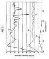
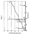
- Fig. 2 and Fig. 3 are graphs showing examples of spectra of a typical disturbance light entering into the vehicle chamber.
- Fig. 2 shows the example of the spectrum of the sunlight
- Fig. 3 shows the example of the spectrum of an artificial light.
- An axis of abscissa in Fig. 2 and Fig. 3 shows the wavelength (unit, nm), and an axis of ordinate shows a spectral irradiance (unit, ⁇ W/cm 2 /nm).
- a curve 101 in Fig. 2 shows the spectrum of the sunlight whose illuminance at a fine weather time is about 100,000 lx
- a curve 102 shows the spectrum of the sunlight whose illuminance at a cloudy weather time is about 30,000 lx
- a curve 103 shows the spectrum of the sunlight whose illuminance in a shade at the fine weather time is about 10,000 lx.
- a curve 111 in Fig. 3 shows the spectrum of a night game illumination
- a curve 112 shows the spectrum of a mercury vapor lamp on a road
- a curve 113 shows the spectrum of the mercury vapor lamp in a parking lot
- a curve 114 shows the spectrum of a sodium vapor lamp
- a curve 115 shows the spectrum of the mercury vapor lamp
- a curve 116 shows the spectrum of a headlight irradiated from a front of 3 m.
- the light quantity of the sunlight is overwhelmingly large in comparison with the light quantity of a light source of other kind. Accordingly, it is desirable to select, as the peak wavelength of the illumination 31, a vicinity of the wavelength in which the intensity of the sunlight is weak.
- the illuminance remarkably attenuates, and becomes smaller than a half in comparison with a value in a vicinity in which a neighboring wavelength is 800 nm or 1000 nm.
- a component in the vicinity of 935 nm is absorbed by a moisture in the atmosphere, and it is a characteristic always seen irrespective of a difference in whether and place, although an attenuating degree somewhat differs.
- Fig. 4 is a graph in which the spectrum of the sunlight in the vicinity of 935 nm is compared by a season.
- a curve 131 shows one example of the spectrum of the sunlight around a noon in a summer
- a curve 132 shows one example of the spectrum of the sunlight around the noon in a winter. From Fig. 4 , the fact is understood that, in the summer and the winter, the spectrum of the sunlight in the vicinity of 935 nm becomes approximately the same tendency.
- the spectrum of the sunlight does not symmetrically change with 935 nm being made a center, but it changes, in a region in which the wavelength is shorter than 935 nm, more steeply in comparison with a region in which the wavelength is longer than 935 nm, and the light quantity becomes large as well. Accordingly, in a case where the peak wavelength of the illumination light of the illumination 31 and the center wavelength of the infrared BPF 42 are made 935 nm, it is necessary to narrow the filter width of the infrared BPF 42 in order to make so as not to undergo an influence of a component, of the sunlight, whose wavelength is shorter than 935 nm.
- the filter width of the infrared BPF 42 is narrowed, the light quantity of the transmitting illumination light is insufficient, so that the driver image becomes dark.
- the infrared BPF 42 is constituted by an interference filter, depending on an incident angle of the light ray, its characteristic shifts to a short wavelength side by about several nm - several tens nm and, even if the filter width is narrowed, there is a possibility that there is subjected to the influence of the component, of the sunlight, whose wavelength is shorter than 935 nm.
- the spectrum of the sunlight also a change is mild in the region in which the wavelength is longer than 935 nm, in comparison with the region in which the wavelength is shorter than 935 nm, and the light quantity becomes small as well. Accordingly, by making the peak wavelength of the illumination light of the illumination 31 and the center wavelength of the infrared BPF 42 into the wavelength longer than 935 nm in the vicinity of 935 nm, it becomes possible to suppress the influence of the sunlight while widening the filter width of the infrared BPF 42.
- Fig. 5 is a graph showing a result in which there was measured a power of the sunlight after being passed through the infrared BPF 42 while changing the center wavelength and a half value breadth of the infrared BPF 42.
- an axis of abscissa shows the wavelength (unit, nm)
- an axis in a depth direction shows the half value breadth (unit, nm)
- an axis of ordinate shows a power (unit, ⁇ W/cm 2 ) of the sunlight.
- Fig. 6 is one in which the graph for every half value breadth is denoted on a two dimension with the axis in the depth direction being deleted from the graph in Fig. 5 .
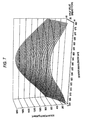
- Fig. 7 is a graph showing a result in which there was measured a power of an LED (Light Emitting Diode) light after being passed through the infrared BPF 42 while changing the center wavelength and the half value breadth of the infrared BPF 42.
- LED Light Emitting Diode
- Fig. 8 is one in which the graph for every half value breadth is denoted on the two dimension with the axis in the depth direction being deleted from the graph in Fig. 7 .
- the powers of the sunlight and the LED light after passing through the infrared BPF 42 change by the center wavelength and the half value breadth of the infrared BPF 42.
- the center wavelength of the infrared BPF 42 is in the vicinity of 940 nm - 950 nm
- the power of the LED light exceeds the power of the sunlight, and a difference between thembecomes the largest. Accordingly, it is considered that it is suitable to set the peak wavelength of the illumination 31 and the center wavelength of the infrared BPF 42 to a degree of 940 nm - 950 nm.
- the illumination light is made an infrared light in which the peak wavelength is made 940 nm - 950 nm, the driver 12 is prevented from being dazzled by the illumination light.
- the half value breadth of the infraredBPF 42 it is considered suitable to set the half value breadth of the infraredBPF 42 to a degree of 40 nm.
- the peak wavelength of the illumination 31 and the center wavelength of the infrared BPF 42 are set to 940 nm, and the half value breadth of the infrared BPF 42 is set to 40 nm.
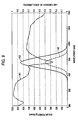
- Fig. 9 is a graph schematically showing examples of relations between [spectra of the sunlight and the illumination light] and [a transmission characteristic of the infrared BPF 42], in a case where the radiation distribution of the illumination 31 is set such that approximately the whole components of the illumination light of the illumination 31 pass through the infrared BPF 42.
- a curve 161 shows an example of the spectrum of the sunlight
- a curve 162 shows an example of the spectrum of the illumination light of the illumination 31
- a curve 163 shows an example of the transmission characteristic of the infrared BPF 42.
- the wavelength of the illumination light of the illumination 31 is approximately included in a range, of the wavelength, in which the incident light transmits through the infrared BPF 42. That is, a radiation characteristic of the illumination 31 is set such that approximately the whole components of the illumination light of the illumination 31 transmit through the infrared BPF 42.
- the monitoring system 11 since the monitoring system 11 is installed in a limited space in the vehicle chamber, there is desired the fact that a size of the illumination 31 is made as small as possible. Accordingly, e.g., an infrared LED which is small and light in weight, or the like is suitable as a light source of the illumination 31.
- the illumination light is irradiated as much as possible to the face of the driver 12 while being concentrated, thereby improving a radiation directional characteristic of the illumination 31.
- it is considered to provide a reflecting plate and the like such that a leak light ray of the illumination 31 is irradiated toward the face of the driver 12.
- the LED since the LED light-emits more brightly the higher a flowing electric current is, it is considered to increase the electric current to be flowed to each LED. However, on the other hand, from viewpoints of the electric power consumption and a calorific value, it is desirable that a magnitude of the electric current to be flowed to the LED is rather as small as possible. Further, if the electric current exceeding a rated current is flowed, the LED is destroyed and, if the electric current near the rated current is continued to be flowed, a life of the LED becomes short. Whereupon, the illumination 31 is pulse-lit by a pulse-like drive electric current as mentioned later by referring to Fig. 15 and Fig. 16 .
- the infrared BPF 42 is constituted, e.g., by the interference filter using a dielectric multilayer film. As mentioned above, the infrared BPF 42 selectively transmits only the light ray in the vicinity of 940 nmwhich is the peak wavelength of the illumination 31. For example, a maximum transmittance of the infrared BPF 42 in regard to the light ray whose wavelength is 940 nm is made about 90%.
- the infrared BPF 42 there is attenuated the light in a wavelength band (e.g., a visible light band or the like) in which the sunlight exceeds the illuminace of the illumination 31, and the light in a wavelength band in which the illuminance of the illumination 31 exceeds the sunlight is extracted and enters to the image pickup element 43.
- a wavelength band e.g., a visible light band or the like
- the light in a wavelength band in which the illuminance of the illumination 31 exceeds the sunlight is extracted and enters to the image pickup element 43.
- the infrared BPF 42 is constituted by the interference filter, it is desirable to install it in such a position that it is not contaminated by contacting with a hand and the like.
- the infrared BPF 42 is constituted, e.g., by a color filter comprising a color glass or plastic etc., other than the interference filter using the dielectric multilayer film.
- the polarizing filters 32, 34 are provided in order to remove or reduce a component in which the illumination light is mirror-reflected by eyeglasses that the driver 12 is wearing, and the like.
- the illumination light is mirror-reflected by the eyeglasses.
- the mirror-reflected light appears in the driver image as a region like a white point. For example, if this region like the white point overlaps with a position of a pupil of the driver 12, such an inconvenience occurs that, in the image processing, a detection of the pupil becomes difficult.
- the polarizing filters 32, 34 correspond together to the infrared light and, as mentioned above, are installed such that their polarization directions mutually, perpendicularly intersect.
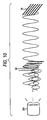
- the polarizing filter 32 and the polarizing filter 34 are disposed such that their polarization faces become mutually parallel and their polarization directions perpendicularly intersect.
- the illumination light of an illumination 201 i.e., the light vibrating approximately, uniformly in all directions perpendicular to a travelling direction.
- the illumination light is polarized in one predetermined direction by the polarizing filter 32 and interrupted approximately, completely by the polarizingfilter 34.
- the illumination light emitted from the illumination 31 and not polarized is polarized in one predetermined direction (hereafter, called an A-direction) by transmitting through the polarizing filter 32.
- the illumination light polarized in the A-direction is irradiated to a subject 210 and reflected.
- the illumination light reflected by the subject 210 includes the light mirror-reflected by the eyeglasses of the driver 12 and the like, and other diffusion-reflected light. Between them, since the mirror-reflected illumination light is polarized in the A-direction, it is approximately interrupted by the polarizing filter 34.
- the diffusion-reflected illumination light is polarized in a direction (hereafter, called a B-direction) perpendicularly intersecting with the A-direction by the polarizing filter 34, and enters to the image pickup section 35. That is, the mirror-reflected component is removed from the reflex light of the illumination light, and additionally the light polarized in the B-direction enters to the image pickup section 35.
- the reflex light of the disturbance light reflected by the subject 210 it is polarized in the B-direction by the polarizing filter 34 irrespective of a difference in the mirror reflex and the diffusion reflex, and enters to the image pickup section 35.
- the disturbance light depending on an angle of the mirror reflex, there is a case where an S-polarization occupies a majority (reflex polarization), and there is a case where the component of the reflex light of the mirror-reflected disturbance light can be also reduced or removed by the fact that the polarizing filter 34 is made a filter in a P-polarization direction.
- the visible light interruption filter 33 is constituted by a filter interrupting the visible light and transmitting the light ray of the wavelength exceeding an infrared region.
- a material and a dye are determined by considering an optical characteristic andanenvironmentaldurability.
- thevisiblelight interruption filter 33 is constituted by kneading the dye absorbing the visible light to acrylic or polycarbonate.
- the visible light interruption filter 33 is provided mainly for the purpose of concealing the image pickup device 21 from the driver 12, and has an advantage relieving such a psychological burden as to "be being monitored” for instance. Further, the visible light interruption filter 33 accomplishes a role protecting an inside of the image pickup device 21 from dusts, water droplets and the like.
- the visible light interruption filter 33 there is selected one of a characteristic sharply interrupting the incident light in a suitable wavelength, and additionally there is combined an infrared interruption filter similarly, sharply interrupting the incident light in the suitable wavelength, thereby constituting, instead of the infrared BPF 42, a BPF by these two interruption filters.
- the infrared interruption filter is transparent one, it is desirable that there is made such that the visible light interruption filter 33 is disposed in the front.
- Fig. 12 is a graph showing an example of a characteristic of the visible light interruption filter 33.
- an axis of abscissa shows the wavelength (unit, nm), and an axis of ordinate shows the transmittance.
- the transmittance of the light whose wavelength is 800 nm or less becomes approximately 0, and the transmittance of the light of 940 nm that is the peak wavelength of the illumination 31 becomes about 0.9.
- the optical lens 41 is constituted by a lens designed so as to image-form in the infrared region while being coincided with the peak wavelength of the illumination 31. By this, it is possible to prevent such an image formation deterioration, which has a possibility occurring when the optical lens for the visible light is used, that the image of the subject to which the infrared light was irradiated becomes hazy by the illumination 31. Further, on the basis of a relative position between the driver 12 and the image pickup device 21, an image pickup distance and the like, the optical lens 41 is designed such that a picture angle, an image periphery distortion or the like becomes a suitable value. Additionally, a material of the optical lens 41 suffices if it is one enduring a use under an environment in the vehicle chamber, and there is used, e.g., a glass or plastic.
- optical lens 41 may be made so as to cause the optical lens 41 to have a function of the infrared BPF 42 by forming the dielectric multilayer film on a lens face of the optical lens 41.
- the image pickup element 43 is an element having a function converting the entering light into an electric signal, and it is constituted, e.g., by the CMOS (Complementary Metal Oxide), the CCD (Charge Coupled Device) and the like. Further, for the image pickup element 43, there is adopted an element in which there is well performed a photoelectric conversion in regard to the light of the wavelength band in which the peak wavelength of the illumination 31is made a center. Further, as mentioned later, since the image pickup element 43 performs an image pickup in an exposure time of a short term while synchronizing with a pulse lighting of the illumination 31, an element having a global shutter function approximately, simultaneously releasing the shutter of all pixels is adopted in the image pickup element 43.
- CMOS Complementary Metal Oxide
- CCD Charge Coupled Device
- Fig. 13 is an exploded view schematically denoting an example of a constitution of the image pickup device 21.
- the polarizing filter 32 is constituted by two polarizing filters of a polarizing filter 32L and a polarizing filter 32R.
- the polarizing filter 32L, the polarizing filter 32R and the polarizing filter 34 are juxtaposed left and right in the order of the polarizing filter 32L, the polarizing filter 34 and the polarizing filter 32R, and disposed so as to be opposed to a face in a side opposite to the subject side of the visible light interruption filter 33.
- the polarizing filter 32L and the polarizing filter 32R and the polarizing filter 34 are disposed such that their polarization directions approximately, perpendicularly intersect.
- the illumination 31 is constituted by LED units 251L, 251R respectively comprising the same number of infrared LEDs, and an illumination substrate 252 for a control.
- An illumination face of the LED unit 251L is covered by the polarizing filter 32L, and the illumination light emitted from the LED unit 251L is irradiated to the subject through the polarizing filter 32L and the visible light interruption filter 33.
- an illumination face of the LED unit 251R is covered by the polarizing filter 32R, and the illumination light emitted from the LED unit 251R is irradiated to the subject through the polarizing filter 32R and the visible light interruption filter 33.
- the illumination substrate 252 there is provided a hole 252A whose size conforms to the optical lens 41.
- the light from the subject passes through the visible light interruption filter 33, the polarizing filter 34 and the hole 252A of the illumination substrate 252, and enters to the optical lens 41 attached to a lens holder 261.
- the light which entered to the optical lens 41 transmits through the infrared BPF 42 provided in a face in a side opposite to the optical lens 41 side of the lens holder 261, and image-forms in an image pickup face of the image pickup element 43. And, the image which was image-picked-up by the image pickup element 43 is supplied to the control section 44.
- the infrared BPF 42 is disposed in front of the image pickup element 43.
- this processing is commenced, e.g., when an engine of own vehicle was started.
- the synchronous control section 51 lights the illumination 31.
- the illumination light of the illumination 31 is irradiated to the driver 12 and the like through the polarizing filter 32 and the visible light interruption filter 33, and its reflex light (hereafter, called an illumination reflex light) enters to the image pickup element 43 through the visible light interruption filter 33, the polarizing filter 34, the optical lens 41 and the infrared BPF 42.
- a reflex light hereafter, called a disturbance reflex light
- the image pickup element 43 through the visible light interruption filter 33, the polarizing filter 34, the optical lens 41 and the infrared BPF 42.
- the image pickup element 43 image-picks-up under the control of the synchronous control section 51. That is, the illumination reflex light and the disturbance reflex light are polarized in a predetermined direction (e.g., a B-direction in Fig. 11 ) and, among the components of the polarized lights, the component in the wavelength band of a predetermined width (e.g., about 40 nm) with the wavelength of 940 nmbeingmade the center is extracted and image-picked-up.
- the image pickup element 43 supplies the driver image obtained as a result of the image pickup to the pixel addition section 52.
- a step S3 the synchronous control section 51 extinguishes the illumination 31.
- onlythedisturbance reflex light enters to the image pickup element 43 through the visible light interruption filter 33, the polarizing filter 34, the optical lens 41 and the infrared BPF 42.
- a step S4 the image pickup element 43 image-picks-up under the control of the synchronous control section 51. That is, the disturbance reflex light are polarized in the predetermined direction (e.g., the B-direction in Fig. 11 ) and, among the components of the polarized light, the component in the wavelength band of the predetermined width (e.g., about 40 nm) with the wavelength of 940 nm being made the center is extracted and image-picked-up.
- the image pickup element 43 supplies the driver image obtained as the result of the image pickup to the pixel addition section 52.
- the number of the LEDs of the illumination 31 and a drive electric current are in a relation of a trade-off. That is, if the number of the LEDs is increased, it is possible to make small the drive electric current per one LED, but the size of the illumination 31 becomes large. Reversely, if the number of the LEDs is decreased, it is possible to make small the size of the illumination 31, but the drive electric current per one LED becomes large.
- a rated value of a pulse-like drive electric current (hereafter, called a pulse drive electric current), which is intermittently flowed in order to flicker the LED, becomes a very large value in comparison with the rated value of a drive electric current (hereafter, called a steady drive electric current) in a case where it is always flowed in order to always light the LED.
- a steady drive electric current a drive electric current
- Its difference is approximately inverse proportion to a lit time of the LED for instance, and becomes about ten times in maximum. Accordingly, by pulse-driving the LED, there is instantaneously obtained the light quantity of about ten times of a steady drive time and, even if the number of the LEDs is reduced, it becomes possible to instantaneously ensure the light quantity exceeding the sunlight.
- the brightness of the driver image depends on an exposure time at an image pickup time. That is, the longer the exposure time is, the more the received light quantity of the image pickup element 43 increases, and the driver image becomes bright. Reversely, the shorter the exposure time is, the more the received light quantity of the image pickup element 43 decreases, and the driver image becomes dark. Accordingly, only by simply shortening the lit time of the illumination 31 and increasing the electric current, a sufficient light quantity is not obtained, so that there is a possibility that there is not obtained the driver image of the brightness necessary for the image processing of the image processing device 22.
- Fig. 15 there are shown three cases in which the lit time and the drive electric current of the illumination 31 were changed.
- the case 1 shows a case where the illumination 31 was lit over the whole term of a frame period and the image pickup element 43 was exposed
- the case 2 shows a case where the illumination 31 was lit by the drive electric current of 300% of the case 1 by a term of 10% of the frame period and the image pickup element 43 was exposed
- the case 3 shows a case where the illumination 31 was lit by the drive electric current of 1000% of the case 1 by a term of 1% of the frame period and the image pickup element 43 was exposed.
- the shutter release time i.e., the exposure time
- the illumination 31 is pulse-lit by a term which is the same as a term in which the shutter of the image pickup device 21 is released for every two frames. That is, there is controlled such that a term in which the illumination 31 is lit synchronizes with a term in which the image pickup element 43 is exposed. Accordingly, the illumination 31 is lit by 0.3 millisecond for every two frames, and the duty ratio becomes about 1% ( ⁇ 0.3 millisecond ⁇ 33 millisecond).
- the term releasing the shutter of the image pickup device 21 is set not always in a forefront of each frame, and there may be made so as to be set in a midway or a tail of each frame. Further, there may be made such that, in the frame (hereafter, called a lit frame as well) in which the illumination 31 is lit and the frame (hereafter, called an extinguished frame) in which the illumination 31 is not lit, a timing releasing the shutter is altered.
- the term shown by the arrow A1 is too short, since there is a case where the illumination light 31 or the processing in the image pickup element 43 does not become in time, it is necessary to consider that point.
- the lit time of the illumination 31 and the shutter release time of the image pickup section 35 are automatically adjusted by detecting the state of the disturbance light, the brightness of circumference, the weather, an opening/closing of window glass, a present time instant, and the like.
- the time releasing the shutter in the lit frame and the time releasing the shutter in the extinguished frame are individually controlled. That is, there may be made such that the shutter release time in the lit frame and the shutter release time in the extinguished frame are set to different values.
- a step S5 the pixel addition section 52 performs a pixel addition processing.
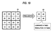
- An image G1 in a left side of Fig. 18 shows an example of the image in a region of 8 x 8 pixels within the driver image.
- Each cell in the image G1 shows the pixel, and a numerical value in the cell shows a pixel value.
- this image G1 is divided into four regions of 2 x 2 pixels and, by adding the pixel value in each region, there is generated an image G2 of 2 x 2 pixels. Accordingly, in comparison with the image G1, the image G2 becomes 1/4 in its resolution, whereas the luminance of each pixel becomes 4 times.
- the processing like this is performed over the whole region of the driver image. That is, the driver image is divided into regions of a predetermined size, and there is generated an image (hereafter, called a pixel addition image as well) comprising the pixels in which the pixel value within the divided region is added. By this, it is possible to increase the luminance of the driver image.
- the size of the region dividing the driver image in the pixel addition processing is set in compliance with the resolution, of the driver image, which is required in the image processing in the image processing device 22 in the post-stage.
- the pixel addition section 52 applies the pixel addition processing to both of the driver image in the lit frame, which was image-picked-up in the step S2, and the driver image in the extinguished frame, which was image-picked-up in the step S3, thereby supplying the two generated pixel addition images to the differential image generating section 53.
- a step S6 there is taken the differential image generating section 53 takes a difference between the images at the lit time and the extinguished time of the illumination 31. That is, by taking the difference between the pixel addition image of the lit frame and the pixel addition image of the extinguished frame, the differential image generating section 53 generates the differential image.
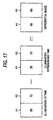
- the pixel values of the pixels P1 and P2 of the differential image together become 60.
- State of light at illumination lit time State of disturbance light at illumination lit time + State of illumination light of illumination 31
- the differential image becomes an image which is suitable for the processing in the image processing device 22, from which the light spot of the face of the driver 12 is removed, and in which the shadow is little.
- the differential image generating section 53 supplies the generated differential image to the image processing device 22.
- the image processing device 22 performs an image processing. That is, the image processing device 22 implements a predetermined monitoring processing by performing a predetermined image processing to the differential image. The image processing device 22 outputs its result to the post-stage device.
- a step S8 the monitoring system 11 judges whether the processing ends. In a case where it is judged that the processing does not end, the processing returns to the step S1, and the processings in the steps S1 to S8 are repeatedly implemented till it is judged in the step S8 that the processing ends.
- the monitoring system 11 judges in the step S8 that the processing ends, and the monitoring processing ends.
- the driver image of the lit frame is made an object of the image processing, e.g., by omitting the processings of the steps S4 to S6.
- the luminance of the driver image is sufficient, there may be made, e.g., such that the pixel addition processing in a step S5 is omitted and, in the step S6, there is taken the difference between the driver image of the lit frame and the driver image of the extinguished frame.
- the present invention can be applied also to a case image-picking-up a rider other than the driver.
- the peak wavelength of the illumination light of the illumination 31 and the center wavelength of the infrared BPF 42 are made 940 nm
- the peak wavelength of the illumination light of the illumination 31 and the center wavelength of the infrared BPF 42 are set to other wavelength in the infrared region in which the intensity (the spectral irradiance) of the sunlight becomes a predetermined threshold value or less and a minimum in the spectrum of the sunlight, or a wavelength (e.g., near 1120 - 1140 nm, near 1400 nm, and the like) in the vicinity of the former.
- the term of the system is made one meaning an overall device constituted by plural units and means, and the like.
- the embodiment of the present invention is not one limited to the above-mentioned embodiment, and various modifications are possible in a scope not deviating from a gist of the present invention.
Landscapes
- Engineering & Computer Science (AREA)
- Multimedia (AREA)
- Signal Processing (AREA)
- Studio Devices (AREA)
- Blocking Light For Cameras (AREA)
Applications Claiming Priority (1)
| Application Number | Priority Date | Filing Date | Title |
|---|---|---|---|
| JP2007217350A JP4915314B2 (ja) | 2007-08-23 | 2007-08-23 | 撮像装置および撮像制御方法 |
Publications (1)
| Publication Number | Publication Date |
|---|---|
| EP2028845A2 true EP2028845A2 (de) | 2009-02-25 |
Family
ID=40091884
Family Applications (1)
| Application Number | Title | Priority Date | Filing Date |
|---|---|---|---|
| EP08161964A Withdrawn EP2028845A2 (de) | 2007-08-23 | 2008-08-07 | Vorrichtung und Verfahren zur Bildaufnahmesteuerung |
Country Status (4)
| Country | Link |
|---|---|
| US (1) | US20090050807A1 (de) |
| EP (1) | EP2028845A2 (de) |
| JP (1) | JP4915314B2 (de) |
| CN (1) | CN101374202A (de) |
Families Citing this family (31)
| Publication number | Priority date | Publication date | Assignee | Title |
|---|---|---|---|---|
| JP5040827B2 (ja) * | 2008-06-20 | 2012-10-03 | 三菱エンジニアリングプラスチックス株式会社 | フィルター用樹脂組成物 |
| JP5288189B2 (ja) * | 2009-03-13 | 2013-09-11 | オムロン株式会社 | 情報処理装置及び方法、並びにプログラム |
| JP2010258636A (ja) * | 2009-04-23 | 2010-11-11 | Alps Electric Co Ltd | 撮像素子ユニット |
| US8432468B2 (en) * | 2009-05-28 | 2013-04-30 | Panasonic Corporation | Composite low frequency cutoff filter and imaging apparatus using the same |
| KR20110056096A (ko) * | 2009-11-20 | 2011-05-26 | 삼성전자주식회사 | 디지털 이미지 처리 장치 및 그 촬영 방법 |
| JP2011139115A (ja) * | 2009-12-25 | 2011-07-14 | Saitama Univ | 高速度カメラ装置とその画像処理方法 |
| JP5437855B2 (ja) * | 2010-03-02 | 2014-03-12 | パナソニック株式会社 | 障害物検知装置およびそれを備えた障害物検知システム、並びに障害物検知方法 |
| JP5060580B2 (ja) | 2010-04-09 | 2012-10-31 | トヨタ自動車株式会社 | スペクトル測定装置 |
| JP5519381B2 (ja) | 2010-04-09 | 2014-06-11 | トヨタ自動車株式会社 | スペクトル測定装置 |
| US8692198B2 (en) * | 2010-04-21 | 2014-04-08 | Sionyx, Inc. | Photosensitive imaging devices and associated methods |
| JP2012080524A (ja) * | 2010-09-09 | 2012-04-19 | Hitachi Kokusai Electric Inc | 監視システム |
| JP2012109767A (ja) * | 2010-11-17 | 2012-06-07 | Sumitomo Electric Ind Ltd | 撮像装置及び撮像システム |
| KR101686079B1 (ko) * | 2010-12-27 | 2016-12-13 | 삼성전자주식회사 | 깊이 영상 생성 장치 및 방법 |
| TWI455298B (zh) * | 2011-10-25 | 2014-10-01 | Pixart Imaging Inc | 感光元件及量測入射光的方法 |
| CN103576724B (zh) * | 2012-08-08 | 2016-08-10 | 联想(北京)有限公司 | 一种图像采集器、电子设备及光线调节方法 |
| JP2014121006A (ja) * | 2012-12-18 | 2014-06-30 | Panasonic Corp | カメラ装置及び撮像方法 |
| JP5821833B2 (ja) | 2012-12-24 | 2015-11-24 | 株式会社デンソー | 撮影装置、近赤外光照射装置、およびサンバイザー |
| US10212355B2 (en) * | 2015-03-13 | 2019-02-19 | Thales Defense & Security, Inc. | Dual-mode illuminator for imaging under different lighting conditions |
| JP6572809B2 (ja) * | 2016-03-15 | 2019-09-11 | オムロン株式会社 | 画像処理装置 |
| JP2017212512A (ja) * | 2016-05-24 | 2017-11-30 | 三星ダイヤモンド工業株式会社 | 撮像装置および画像管理システム |
| JP2019514302A (ja) * | 2016-05-25 | 2019-05-30 | エムテクビジョン カンパニー リミテッド | 運転者の目位置の検出装置と方法、及びローリングシャッター駆動方式のイメージセンサーを備えた撮像装置とその照明制御方法 |
| JP6780856B2 (ja) * | 2017-03-31 | 2020-11-04 | 日本電気株式会社 | 画像取得装置、スタンド型スキャナ装置および画像取得方法 |
| DE102017217486A1 (de) * | 2017-09-29 | 2019-04-04 | Robert Bosch Gmbh | Fahrerbeobachtungssystem, Verfahren zum Erfassen eines Fahrers mittels eines Fahrerbeobachtungssystems und Verfahren zum Herstellen einer Wellenlängenschiebereinheit für ein Fahrerbeobachtungssystem |
| DE102018104906B3 (de) * | 2018-03-05 | 2018-12-13 | Sick Ag | Kamera |
| CN108596035A (zh) * | 2018-03-26 | 2018-09-28 | 维沃移动通信有限公司 | 一种人脸识别方法和终端设备 |
| JP7042465B2 (ja) * | 2018-09-20 | 2022-03-28 | パナソニックIpマネジメント株式会社 | 光源ユニット、及び移動体 |
| JP7213466B2 (ja) * | 2019-03-28 | 2023-01-27 | パナソニックIpマネジメント株式会社 | カメラシステム、搭乗者監視システム、移動装置、撮像方法及びプログラム |
| CN111866313A (zh) * | 2019-04-26 | 2020-10-30 | 致伸科技股份有限公司 | 摄像模块 |
| JP2021043296A (ja) * | 2019-09-10 | 2021-03-18 | 株式会社ミツトヨ | 画像検出装置 |
| JP7468885B2 (ja) | 2020-01-20 | 2024-04-16 | i-PRO株式会社 | カメラ装置 |
| US12170842B2 (en) * | 2021-04-05 | 2024-12-17 | Canon Kabushiki Kaisha | Illumination control device, imaging device, and storage medium |
Citations (1)
| Publication number | Priority date | Publication date | Assignee | Title |
|---|---|---|---|---|
| JP2000028315A (ja) | 1998-07-13 | 2000-01-28 | Honda Motor Co Ltd | 対象物検出装置 |
Family Cites Families (10)
| Publication number | Priority date | Publication date | Assignee | Title |
|---|---|---|---|---|
| US5668631A (en) * | 1993-12-20 | 1997-09-16 | Minolta Co., Ltd. | Measuring system with improved method of reading image data of an object |
| JPH0968742A (ja) * | 1995-08-31 | 1997-03-11 | Nissin Electric Co Ltd | 撮影装置 |
| JP2000324406A (ja) * | 1999-05-07 | 2000-11-24 | Canon Inc | 光電変換装置及びそれを用いた画像読み取りシステム |
| US7217573B1 (en) * | 1999-10-05 | 2007-05-15 | Hitachi, Ltd. | Method of inspecting a DNA chip |
| JP2001169147A (ja) * | 1999-12-09 | 2001-06-22 | Nippon Avionics Co Ltd | 画像入力装置の撮像光学系 |
| US7102680B2 (en) * | 2000-03-13 | 2006-09-05 | Olympus Corporation | Image pickup device capable of adjusting the overflow level of the sensor based on the read out mode |
| JP4442539B2 (ja) * | 2005-09-27 | 2010-03-31 | パナソニック電工株式会社 | 空間情報の検出装置 |
| JP2006178320A (ja) * | 2004-12-24 | 2006-07-06 | Olympus Corp | 分光透過率可変素子、及び分光透過率可変素子を備えた内視鏡装置 |
| JP4497022B2 (ja) * | 2005-04-26 | 2010-07-07 | ソニー株式会社 | 固体撮像装置、固体撮像装置の駆動方法および撮像装置 |
| JP4999306B2 (ja) * | 2005-09-30 | 2012-08-15 | カシオ計算機株式会社 | 撮像装置、撮影方法及びプログラム |
-
2007
- 2007-08-23 JP JP2007217350A patent/JP4915314B2/ja not_active Expired - Fee Related
-
2008
- 2008-07-16 CN CNA2008101315291A patent/CN101374202A/zh active Pending
- 2008-08-07 EP EP08161964A patent/EP2028845A2/de not_active Withdrawn
- 2008-08-19 US US12/193,910 patent/US20090050807A1/en not_active Abandoned
Patent Citations (1)
| Publication number | Priority date | Publication date | Assignee | Title |
|---|---|---|---|---|
| JP2000028315A (ja) | 1998-07-13 | 2000-01-28 | Honda Motor Co Ltd | 対象物検出装置 |
Also Published As
| Publication number | Publication date |
|---|---|
| US20090050807A1 (en) | 2009-02-26 |
| JP2009055107A (ja) | 2009-03-12 |
| CN101374202A (zh) | 2009-02-25 |
| JP4915314B2 (ja) | 2012-04-11 |
Similar Documents
| Publication | Publication Date | Title |
|---|---|---|
| EP2028845A2 (de) | Vorrichtung und Verfahren zur Bildaufnahmesteuerung | |
| RU2755834C1 (ru) | Электронные очки | |
| US10426667B2 (en) | Automatic darkening filter apparatus and method | |
| KR100449552B1 (ko) | 자동차용 적외광 조사 램프 | |
| WO2013144003A1 (fr) | Lunettes adaptatives pour conducteur ou passager de véhicule automobile | |
| FR2988333A1 (fr) | Procede et dispositif d'aide a la conduite nocturne des vehicules automobiles | |
| AU8409091A (en) | Surveillance apparatus particularly for use in viewing vehicle number-plates | |
| JP4232498B2 (ja) | 被写体撮影状態判定装置、画質調整装置、及び画像撮影装置 | |
| CN110445990B (zh) | 一种补光装置及拍摄系统 | |
| CN1187252A (zh) | 光强度衰减装置和衰减方法 | |
| WO2020255824A1 (ja) | 車載赤外線照明装置 | |
| KR102017826B1 (ko) | 고품질의 야간 컬러영상을 제공하는 감시카메라 | |
| JP2004297645A (ja) | 撮像システム | |
| CN109398046A (zh) | 一种动态百叶窗式防眩光遮阳板系统及其遮光方法 | |
| US10051195B2 (en) | Apparatus and method for acquiring differential image | |
| KR100554501B1 (ko) | 감시카메라의 역광차단장치 | |
| CN206226579U (zh) | 可穿戴防强光设备 | |
| RU2806339C1 (ru) | Электронные очки | |
| RU2792656C1 (ru) | Электронные очки | |
| CN211089721U (zh) | 一种监控装置 | |
| KR200323585Y1 (ko) | 착탈식 적외선 차단필터를 이용한 흑백 칼라 겸용전하결합소자 카메라의 촬영을 위한 제어시스템 | |
| RU450U1 (ru) | Телекамера на ПЗС | |
| KR102014722B1 (ko) | 눈부심 방지 조명장치 | |
| KR19980047573A (ko) | 얼굴화상 촬상장치 | |
| KR20110120706A (ko) | 레이저 감시장치의 안전장치 및 그 제어방법 |
Legal Events
| Date | Code | Title | Description |
|---|---|---|---|
| PUAI | Public reference made under article 153(3) epc to a published international application that has entered the european phase |
Free format text: ORIGINAL CODE: 0009012 |
|
| AK | Designated contracting states |
Kind code of ref document: A2 Designated state(s): AT BE BG CH CY CZ DE DK EE ES FI FR GB GR HR HU IE IS IT LI LT LU LV MC MT NL NO PL PT RO SE SI SK TR |
|
| AX | Request for extension of the european patent |
Extension state: AL BA MK RS |
|
| STAA | Information on the status of an ep patent application or granted ep patent |
Free format text: STATUS: THE APPLICATION HAS BEEN WITHDRAWN |
|
| 18W | Application withdrawn |
Effective date: 20100824 |