EP2024682B1 - Verfahren zur verbesserung der schlackequalität von rostfeuerungsanlagen - Google Patents
Verfahren zur verbesserung der schlackequalität von rostfeuerungsanlagen Download PDFInfo
- Publication number
- EP2024682B1 EP2024682B1 EP07725507.3A EP07725507A EP2024682B1 EP 2024682 B1 EP2024682 B1 EP 2024682B1 EP 07725507 A EP07725507 A EP 07725507A EP 2024682 B1 EP2024682 B1 EP 2024682B1
- Authority
- EP
- European Patent Office
- Prior art keywords
- bed
- combustion
- fixed
- burn
- grate
- Prior art date
- Legal status (The legal status is an assumption and is not a legal conclusion. Google has not performed a legal analysis and makes no representation as to the accuracy of the status listed.)
- Not-in-force
Links
- 239000002893 slag Substances 0.000 title claims description 46
- 238000000034 method Methods 0.000 title claims description 27
- 230000006872 improvement Effects 0.000 title claims description 4
- 238000002485 combustion reaction Methods 0.000 claims description 109
- 239000007789 gas Substances 0.000 claims description 43
- QVGXLLKOCUKJST-UHFFFAOYSA-N atomic oxygen Chemical compound [O] QVGXLLKOCUKJST-UHFFFAOYSA-N 0.000 claims description 25
- 229910052760 oxygen Inorganic materials 0.000 claims description 25
- 239000001301 oxygen Substances 0.000 claims description 25
- 239000000567 combustion gas Substances 0.000 claims description 12
- UGFAIRIUMAVXCW-UHFFFAOYSA-N Carbon monoxide Chemical compound [O+]#[C-] UGFAIRIUMAVXCW-UHFFFAOYSA-N 0.000 claims description 7
- 238000001816 cooling Methods 0.000 claims description 3
- 229910002091 carbon monoxide Inorganic materials 0.000 claims 3
- 239000012466 permeate Substances 0.000 claims 2
- 238000005259 measurement Methods 0.000 claims 1
- 239000000155 melt Substances 0.000 claims 1
- 239000000446 fuel Substances 0.000 description 54
- OKTJSMMVPCPJKN-UHFFFAOYSA-N Carbon Chemical compound [C] OKTJSMMVPCPJKN-UHFFFAOYSA-N 0.000 description 30
- 229910052799 carbon Inorganic materials 0.000 description 30
- 239000002737 fuel gas Substances 0.000 description 17
- 238000005245 sintering Methods 0.000 description 14
- VEXZGXHMUGYJMC-UHFFFAOYSA-M Chloride anion Chemical compound [Cl-] VEXZGXHMUGYJMC-UHFFFAOYSA-M 0.000 description 8
- 239000004449 solid propellant Substances 0.000 description 8
- 238000002474 experimental method Methods 0.000 description 7
- 238000004056 waste incineration Methods 0.000 description 7
- 238000007872 degassing Methods 0.000 description 6
- 239000000470 constituent Substances 0.000 description 5
- 238000001035 drying Methods 0.000 description 5
- 238000010304 firing Methods 0.000 description 5
- 238000002844 melting Methods 0.000 description 5
- 230000008018 melting Effects 0.000 description 5
- 230000008569 process Effects 0.000 description 5
- 238000004064 recycling Methods 0.000 description 5
- 239000003546 flue gas Substances 0.000 description 4
- 239000007787 solid Substances 0.000 description 4
- 230000000694 effects Effects 0.000 description 3
- 239000003344 environmental pollutant Substances 0.000 description 3
- 238000002156 mixing Methods 0.000 description 3
- 231100000719 pollutant Toxicity 0.000 description 3
- 239000000243 solution Substances 0.000 description 3
- 230000001988 toxicity Effects 0.000 description 3
- 231100000419 toxicity Toxicity 0.000 description 3
- 230000015572 biosynthetic process Effects 0.000 description 2
- 239000012141 concentrate Substances 0.000 description 2
- 230000006378 damage Effects 0.000 description 2
- 238000000605 extraction Methods 0.000 description 2
- 239000003517 fume Substances 0.000 description 2
- 238000010438 heat treatment Methods 0.000 description 2
- JEIPFZHSYJVQDO-UHFFFAOYSA-N iron(III) oxide Inorganic materials O=[Fe]O[Fe]=O JEIPFZHSYJVQDO-UHFFFAOYSA-N 0.000 description 2
- 239000000203 mixture Substances 0.000 description 2
- 238000005457 optimization Methods 0.000 description 2
- 238000012360 testing method Methods 0.000 description 2
- 239000003039 volatile agent Substances 0.000 description 2
- 239000002699 waste material Substances 0.000 description 2
- 239000002028 Biomass Substances 0.000 description 1
- 238000013459 approach Methods 0.000 description 1
- 235000010633 broth Nutrition 0.000 description 1
- 230000008859 change Effects 0.000 description 1
- 239000007795 chemical reaction product Substances 0.000 description 1
- 239000003245 coal Substances 0.000 description 1
- 239000010791 domestic waste Substances 0.000 description 1
- 238000011143 downstream manufacturing Methods 0.000 description 1
- 239000008187 granular material Substances 0.000 description 1
- 238000002347 injection Methods 0.000 description 1
- 239000007924 injection Substances 0.000 description 1
- 238000010309 melting process Methods 0.000 description 1
- 230000003647 oxidation Effects 0.000 description 1
- 238000007254 oxidation reaction Methods 0.000 description 1
- 230000036284 oxygen consumption Effects 0.000 description 1
- 230000000737 periodic effect Effects 0.000 description 1
- 239000002957 persistent organic pollutant Substances 0.000 description 1
- 239000000047 product Substances 0.000 description 1
- 230000005855 radiation Effects 0.000 description 1
- 230000009467 reduction Effects 0.000 description 1
- 238000005070 sampling Methods 0.000 description 1
- 238000013517 stratification Methods 0.000 description 1
- 230000002123 temporal effect Effects 0.000 description 1
- 238000007669 thermal treatment Methods 0.000 description 1
- 238000011144 upstream manufacturing Methods 0.000 description 1
- XLYOFNOQVPJJNP-UHFFFAOYSA-N water Substances O XLYOFNOQVPJJNP-UHFFFAOYSA-N 0.000 description 1
Images
Classifications
-
- F—MECHANICAL ENGINEERING; LIGHTING; HEATING; WEAPONS; BLASTING
- F23—COMBUSTION APPARATUS; COMBUSTION PROCESSES
- F23C—METHODS OR APPARATUS FOR COMBUSTION USING FLUID FUEL OR SOLID FUEL SUSPENDED IN A CARRIER GAS OR AIR
- F23C9/00—Combustion apparatus characterised by arrangements for returning combustion products or flue gases to the combustion chamber
- F23C9/006—Combustion apparatus characterised by arrangements for returning combustion products or flue gases to the combustion chamber the recirculation taking place in the combustion chamber
-
- F—MECHANICAL ENGINEERING; LIGHTING; HEATING; WEAPONS; BLASTING
- F23—COMBUSTION APPARATUS; COMBUSTION PROCESSES
- F23G—CREMATION FURNACES; CONSUMING WASTE PRODUCTS BY COMBUSTION
- F23G5/00—Incineration of waste; Incinerator constructions; Details, accessories or control therefor
- F23G5/002—Incineration of waste; Incinerator constructions; Details, accessories or control therefor characterised by their grates
-
- F—MECHANICAL ENGINEERING; LIGHTING; HEATING; WEAPONS; BLASTING
- F23—COMBUSTION APPARATUS; COMBUSTION PROCESSES
- F23G—CREMATION FURNACES; CONSUMING WASTE PRODUCTS BY COMBUSTION
- F23G5/00—Incineration of waste; Incinerator constructions; Details, accessories or control therefor
- F23G5/50—Control or safety arrangements
-
- F—MECHANICAL ENGINEERING; LIGHTING; HEATING; WEAPONS; BLASTING
- F23—COMBUSTION APPARATUS; COMBUSTION PROCESSES
- F23C—METHODS OR APPARATUS FOR COMBUSTION USING FLUID FUEL OR SOLID FUEL SUSPENDED IN A CARRIER GAS OR AIR
- F23C2900/00—Special features of, or arrangements for combustion apparatus using fluid fuels or solid fuels suspended in air; Combustion processes therefor
- F23C2900/09002—Specific devices inducing or forcing flue gas recirculation
-
- F—MECHANICAL ENGINEERING; LIGHTING; HEATING; WEAPONS; BLASTING
- F23—COMBUSTION APPARATUS; COMBUSTION PROCESSES
- F23G—CREMATION FURNACES; CONSUMING WASTE PRODUCTS BY COMBUSTION
- F23G2202/00—Combustion
- F23G2202/10—Combustion in two or more stages
- F23G2202/104—Combustion in two or more stages with ash melting stage
-
- F—MECHANICAL ENGINEERING; LIGHTING; HEATING; WEAPONS; BLASTING
- F23—COMBUSTION APPARATUS; COMBUSTION PROCESSES
- F23G—CREMATION FURNACES; CONSUMING WASTE PRODUCTS BY COMBUSTION
- F23G2202/00—Combustion
- F23G2202/10—Combustion in two or more stages
- F23G2202/106—Combustion in two or more stages with recirculation of unburned solid or gaseous matter into combustion chamber
-
- F—MECHANICAL ENGINEERING; LIGHTING; HEATING; WEAPONS; BLASTING
- F23—COMBUSTION APPARATUS; COMBUSTION PROCESSES
- F23G—CREMATION FURNACES; CONSUMING WASTE PRODUCTS BY COMBUSTION
- F23G2203/00—Furnace arrangements
- F23G2203/101—Furnace arrangements with stepped or inclined grate
-
- F—MECHANICAL ENGINEERING; LIGHTING; HEATING; WEAPONS; BLASTING
- F23—COMBUSTION APPARATUS; COMBUSTION PROCESSES
- F23G—CREMATION FURNACES; CONSUMING WASTE PRODUCTS BY COMBUSTION
- F23G2207/00—Control
- F23G2207/30—Oxidant supply
-
- Y—GENERAL TAGGING OF NEW TECHNOLOGICAL DEVELOPMENTS; GENERAL TAGGING OF CROSS-SECTIONAL TECHNOLOGIES SPANNING OVER SEVERAL SECTIONS OF THE IPC; TECHNICAL SUBJECTS COVERED BY FORMER USPC CROSS-REFERENCE ART COLLECTIONS [XRACs] AND DIGESTS
- Y02—TECHNOLOGIES OR APPLICATIONS FOR MITIGATION OR ADAPTATION AGAINST CLIMATE CHANGE
- Y02E—REDUCTION OF GREENHOUSE GAS [GHG] EMISSIONS, RELATED TO ENERGY GENERATION, TRANSMISSION OR DISTRIBUTION
- Y02E20/00—Combustion technologies with mitigation potential
- Y02E20/34—Indirect CO2mitigation, i.e. by acting on non CO2directly related matters of the process, e.g. pre-heating or heat recovery
Definitions
- the invention relates to a method for improving the slag quality of grate firing systems, such as e.g. Waste incineration plants according to the first claim.
- the combustion of solid fuels such as waste, biomass or coal on combustion broths can ideally be divided into the successive partial processes of drying, devolatilization of the volatile constituents, combustion of the residual carbon and sintering of the grate ash.
- the mixing of the fuel is very poor, in particular with feed grates, as a result of which the subprocesses are superimposed over the grate length.
- the combustible fuel fraction concentrates predominantly in the volatiles that are released after drying. These high-calorie gases released during the degassing partly burn, depending on the locally available oxygen, predominantly above the fuel bed, as a result of which the local exhaust-gas temperature rises sharply.
- the remaining in the fuel bed fixed carbon is only a small proportion of the total carbon inventory but requires much more time to burn out. Therefore, the area for the residual carbon burn occupies a disproportionately large area of the grate.
- An increase in the burning rate of the fixed carbon by increasing the temperature in the area of the slag burning zone, in addition to an improvement in the quality of the slag, also makes it possible to increase the fuel throughput. Both effects have considerable economic importance.
- the slag is usually used as a broken granules as Bauzutschstoff.
- the aim of improving the slag quality is therefore as complete as possible a carbon burnout, sintering and / or melting of the combustion residues either in a still in the fuel bed or the combustion downstream thermal aftertreatment, but also in achieving a low pollutant content (eg PCDD / F).
- DE 199 61 384 A1 a method for the thermal treatment of grate ash from waste incineration plants is known, in which the grate ash is passed after the combustion in a rotary tube and thermally treated there by means of another fuel with oxygen supply.
- DE 102 13 788 A1 discloses a method for influencing combustion residues from a waste incineration plant without a downstream process step in a separate device. The sintering and / or melting process of the slag is carried out in this process still in the fuel bed of the main combustion zone, wherein the non-sintered or molten combustion residues are re-cycled after passing through the fuel bed in the combustion process.
- EP941777A describes a method according to the preamble of claim 1.
- any additional process step even if it involves recycling of constituents without an additional process chamber, entails considerable expense that directly pays off in the economics of an incinerator. This is especially true for an additional slag treatment with an additional expensive oxygen enrichment> 21 vol.%.
- High temperatures are a prerequisite for slag optimization.
- an oxygen enrichment of the combustion air favors high temperature levels, but essentially only in the gas space above the fixed bed Ausbrandzone and not within the entire fuel bed, which is crucial for the quality of the slag.
- the object of the invention is to propose a simple and reliably controllable method for improving the slag quality in waste incineration, for example grate furnaces, in which a good slag quality is achieved even during the fixed bed combustion on the grate. It is of particular importance that no other pollutants such as NO x and / or no significant reduction in the energetic use of the heat content of the combustion exhaust gases occurs by the process.
- An essential feature of the solution is the targeted heating of the fuel bed (ie solid fuel with possibly formed slag and ash) on the combustion grate in the region of at least one fixed bed combustion zone by recycling combustion gases from the combustion chamber via at least one of these fixed bed combustion zones.
- Hot fuel gas partial streams are branched off directly from the combustion chamber via at least one fixed-bed burn-off zone and passed through the combustion bed of at least one subsequent, preferably the last fixed-bed burn-out zone.
- high temperature of the fuel gas is advantageously utilized for an additional increase in temperature in the fuel bed in the above-mentioned subsequent, ie preferably at least one of the last Festbettausbrandzonen.
- a fuel undergoes successively through a combustion on a grate furnace all Festbettausbrandzonen, it comes with the passage in the front (first) Festbettausbrandzonen to an increasing burnup of the combustible fractions of the fuel to form ash and slag components.
- first Festbettausbrandzonen preferably last Festbettausbrandzonen then cumulate this slag constituents, which there basically sets a low temperature level due to the already largely carried out burnout of the solid and by the supplied in this grate zone cold primary gas.
- the slag components are specifically heated there and thus enable sintering to a slag with improved quality.
- the slag thus already leaves the fixed-bed burn-out zone as a sintered end product of improved quality. Thermal aftertreatments are no longer required. Also, a supply of expensive oxygen for a sintering of the slag is no longer necessary.
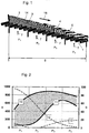
- the fuel bed of a conventional grate furnace includes a combustion grate 1 with four fixed bed combustion zones P 1 to P 4 , which are passed through by a solid fuel (fuel bed 14 ) during combustion sequentially.
- the combustion of the solid fuel on the combustion grate goes through the following sub-processes: drying 2, degassing 3 of the volatile waste components, burn-off 4 of the residual carbon and sintering of the grate ash 5.
- these sub-processes are superimposed on the grate length 6.
- the burning of the solid takes place essentially from the fuel bed surface in the direction of the combustion grate. This characteristic causes a pronounced vertical temperature profile over the bed thickness.
- an oxygen-containing primary gas feed 7 takes place.
- the combustible fraction of the solid fuel concentrates predominantly in the volatile constituents released during degassing 3 after drying 2 .
- These high-calorie gases released during degassing partly burn, depending on the oxygen locally provided by the primary gas supply, for the most part above the combustion bed, as a result of which the local exhaust-gas temperature rises sharply.
- Residual carbon comprises only a very small proportion of the total carbon inventory, but requires much more time for a burnout. Therefore, the range for the residual carbon burn occupies a disproportionately large area of the combustion grate.
- Increasing the burning rate of the fixed carbon by increasing the temperature generally allows an improvement as well slag quality (low Cl, TOC and PCDD / F concentrations) also increases fuel throughput.
- the kinetics of the combustion of the residual carbon depends in particular on the local temperature in the fuel bed and on the oxygen supply in the last fixed bed burnout zone. This situation is evident in the different position of the temperature maxima in the combustion grate compared with the temperature profile in the exhaust gas above the combustion bed.
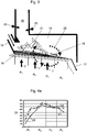
- Fig.2 shows typical axial temperature curves 8 in ° C measured at a waste incineration plant (TAMARA in the research center Düsseldorf) as well as determined concentrations 9 in% for the carbon burnup 12 of the fuel bed and in% by volume for the oxygen concentration 13 above the combustion bed, applied over the four fixed bed burnout zones P 1 to P 4 of a combustion chamber.
- the burned solid fuel consisted of 29% water, 39% volatiles, 5% residual carbon and 27% ash, representing a typical composition of household waste.
- Between the temperature curves above the combustion bed 10 and directly at the grate surface 11 shows a partially significant temperature gradient between the values.
- Fig.2 the burnup curve of the total carbon content 12 in the fuel bed and the oxygen concentration 13 above the fuel bed.
- the main combustion zone (fixed bed burnout zone P 2 ) is characterized by a high local carbon burn rate, and consequently by a high oxygen consumption, which is shown in O 2 Minimum of the oxygen concentration 13 .
- the release of the high-calorie volatile constituents is so great here that the oxygen available locally via the primary air is insufficient to ensure complete oxidation directly in and above the combustion bed.
- the complete gas burnout then takes place in a downstream exhaust gas burnout zone (compare 19 in Figure 3 ) under secondary gas injection (compare 20 in Figure 3 ).
- the carbon concentration 12 in the fuel bed continuously drops and approaches asymptotically towards 0.
- TOC contents TOC: total organic carbon content
- From Festbettausbrandzone P 3 takes place essentially the burn-out of the fixed carbon (residual carbon).
- the measured temperatures drop significantly, which is attributable to the fact that the supplied primary air excess in this fixed-bed burn-out zone leads to a high lean stoichiometric ratio compared to the residual carbon content in the fuel bed.
- the oxygen concentration 13 increases to about 18%.
- FIG. 3 shows a two-stage incinerator of the type mentioned, but with a schematically illustrated deflection of combustion gas by the last fixed bed burn-out zone as a solution to the aforementioned object.
- the system consists essentially of a fuel bed 14 on a combustion grate 1 in a combustion chamber 15 with an inlet 16 for fuel, an outlet 17 (see FIG. 18 in fuel transport direction Fig.1 ) for slag or other solid combustion products as well as a combustion chamber downstream Abgasausbrandzone 19 in the exhaust fume hood.
- the combustion chamber 15 covers all Festbettausbrandzonen P 1 to P 4 , which are passed through in series by the fuel in the fuel bed.
- the fixed bed burnout zones P 1 to P 3 are respectively flowed through the combustion grate with an individual oxygen-containing primary gas feed 7 per fixed-bed burn-out zone, whereas in the present embodiment no primary gas flow through the combustion bed takes place in the fixed-bed burn-out zone P 4 .
- An oxygen-containing Sekundärgaseindüsung 20 takes place in the downstream Abgasausbrandzone 19 in the exhaust fume.
- Good slag quality is characterized by low residual carbon (TOC) and chloride concentrations as well as organic pollutants (eg PCDD / F). This is ensured by a sufficiently long residence time of the slag at high temperatures in the second half of the grate (in the example: fixed-bed combustion zones P 3 and P 4 ), especially in the last fixed bed burn-out zone P 4 . There are, however Bed temperatures above 1000 ° C, preferably greater than 1100 ° C, (the slag melting temperature) to avoid, as this may lead to damage or destruction of the grate.
- a setting of the desired temperatures in the fuel bed of Festbettausbrandzone P 4 is preferably carried out via a control of the flowing (ie aspirated) fuel gas or a temporal change (eg periodic) of suction (fuel gas flow) or primary gas (primary gas flow).
- a minimum temperature of 600 ° C measured in the combustion grate of the last (or the following subsequent fixed bed burnout zone) at residence times of the fuel bed greater than 10 minutes is required.
- the exceeding sintering temperature is usually at least 60 to 70% of the slag melting temperature in ° C.
- the firing bed temperature in the fixed-bed burn-out zone P 4 is preferably at 800 ° C. to at most 1000 ° C.
- the surface of the slag layer preferably measured with a radiation pyrometer.
- Long residence times of the slag during sintering in the last fixed bed burnout zone P 4 are set by low rust rates.
- the resulting accumulating high slag layer has a pronounced temperature gradient due to poor mixing.
- the slag bed cools down considerably and only a very small amount of carbon burns out in this area.
- the abovementioned temperature level between the sintering and melting temperatures preferably between 800 and 1000 ° C., is achieved by diverting fuel gases from the combustion chamber and, preferably, divert them over the shortest possible paths for the flow through the combustion bed on the fixed-bed burn-out zone P 4 .
- the fuel gases from the combustion chamber are thereby preferably with a temperature level (see. Fig.2 , for example, about 900 ° C temperature profile 10 ), ie branched off in the area above the fixed bed combustion zone P 2 and P 3 and directly, passed from top to bottom through the fuel bed in the fixed bed Ausbrandzone P 4 .
- a temperature level see. Fig.2 , for example, about 900 ° C temperature profile 10
- a temperature level see. Fig.2 , for example, about 900 ° C temperature profile 10
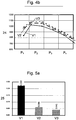
- the fuel gases flowing through the combustion grate 1 in the fixed-bed combustion zone P 4 are then supplied to the primary gas supply 7 or returned to the combustion chamber above the combustion grate, whereby a recycling cycle 22 for the hot combustion gases is produced. Since the recycled gas from P4 still has a considerable oxygen content, partial combustion of the high-calorie fuel gases from P2 occurs. This results in an increase of the temperatures in the combustion chamber (cf. 4a ). By adjusting itself higher temperature level of the fuel gases, the temperature in the fuel bed of the fixed bed Ausbrandzone P 4 also increases. It is also essential that the fuel gas or exhaust gas has a sufficient amount of oxygen for the residual carbon burn of the fuel bed in Festbettausbrandzone P 4 .
- the recycling of the fuel gases preferably takes place from top to bottom through the combustion bed by means of a circulating means, preferably an injector or a hot gas blower, preferably arranged as a suction device below the combustion grate 1 in the last grate zone.
- the fuel gas advantageously emits a large part of the heat to the fuel bed.
- the temperature-sensitive moving parts of the plant preferably air
- the extracted fuel gas amount is limited according to the maximum allowable grate temperature (and the aforementioned melting temperature of the slag).
- 4a and b show the grate temperatures 23 determined in three experiments ( V1, V2, V3 ) at a waste incineration plant (TAMARA of the Research Center Düsseldorf) with grate firing.
- 4a and flue gas temperatures 24 (combustion gas temperatures in the combustion chamber, 4b ) over the aforementioned four fixed bed burnout zones applied over the fixed bed burnout zones.
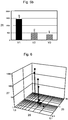
- 5a and b give TOC concentrations 25 % (cf. 5a ) and chloride contents 26 mg / kg (cf. 5 b ) in the slag (dry sampling) over the above three experiments again.
- an extraction of the recycled fuel gas by means of an injector by the fuel bed in the last fixed bed combustion zone and a return of the recycled fuel gas into the combustion chamber over the fixed bed Ausbrandzone P 2nd
- Experiment V1 served as a reference experiment without recycle fuel gas according to the invention.
- the fixed-bed combustion zones P 1 to P 4 were flowed through with 50/100/100/50 m 3 / h primary gas.
- the corresponding fuel residence times set in the individual fixed bed burnout zones P 1 to P 4 via the grate drive were 300/300/600/1200 s.
Landscapes
- Engineering & Computer Science (AREA)
- Mechanical Engineering (AREA)
- General Engineering & Computer Science (AREA)
- Chemical & Material Sciences (AREA)
- Combustion & Propulsion (AREA)
- Incineration Of Waste (AREA)
- Gasification And Melting Of Waste (AREA)
- Combustion Of Fluid Fuel (AREA)
Applications Claiming Priority (2)
| Application Number | Priority Date | Filing Date | Title |
|---|---|---|---|
| DE102006026434A DE102006026434B3 (de) | 2006-06-07 | 2006-06-07 | Verfahren zur Verbesserung der Schlackequalität von Rostfeuerungsanlagen |
| PCT/EP2007/004607 WO2007140885A1 (de) | 2006-06-07 | 2007-05-24 | Verfahren zur verbesserung der schlackequalität von rostfeuerungsanlagen |
Publications (2)
| Publication Number | Publication Date |
|---|---|
| EP2024682A1 EP2024682A1 (de) | 2009-02-18 |
| EP2024682B1 true EP2024682B1 (de) | 2018-10-03 |
Family
ID=38325443
Family Applications (1)
| Application Number | Title | Priority Date | Filing Date |
|---|---|---|---|
| EP07725507.3A Not-in-force EP2024682B1 (de) | 2006-06-07 | 2007-05-24 | Verfahren zur verbesserung der schlackequalität von rostfeuerungsanlagen |
Country Status (6)
| Country | Link |
|---|---|
| US (1) | US8210112B2 (enExample) |
| EP (1) | EP2024682B1 (enExample) |
| JP (1) | JP5237936B2 (enExample) |
| KR (1) | KR101393958B1 (enExample) |
| DE (1) | DE102006026434B3 (enExample) |
| WO (1) | WO2007140885A1 (enExample) |
Families Citing this family (4)
| Publication number | Priority date | Publication date | Assignee | Title |
|---|---|---|---|---|
| DE102012000262B4 (de) | 2012-01-10 | 2015-12-17 | Jörg Krüger | Verfahren und Vorrichtung zur Verbesserung des Ausbrandes von Schlacken auf Verbrennungsrosten |
| CN104676627B (zh) * | 2015-01-23 | 2017-01-11 | 浙江森炉节能环保科技有限公司 | 一种锅炉的进料除灰系统 |
| DE102015003995A1 (de) * | 2015-03-30 | 2016-10-06 | Martin GmbH für Umwelt- und Energietechnik | Verfahren zur Verbrennungsführung bei Rostfeuerungen sowie Rostfeuerung |
| CN114729745B (zh) * | 2019-11-29 | 2025-08-01 | 三菱重工业株式会社 | 机械炉排炉 |
Family Cites Families (33)
| Publication number | Priority date | Publication date | Assignee | Title |
|---|---|---|---|---|
| CH417833A (de) * | 1963-11-11 | 1966-07-31 | Von Roll Ag | Verbrennungsofen mit einer Mehrzonen-Rostfeuerung zur Vernichtung von vorher teilweise entwässertem Schlamm mit niedrigem Heizwert und hohem Anteil an unbrennbaren Bestandteilen, wie z. B. Klärschlamm |
| CH405577A (de) * | 1963-11-27 | 1966-01-15 | Von Roll Ag | Verfahren zur Verbrennung von sperrigen Brennstoffen unterschiedlicher Beschaffenheit mittels einer mechanischen Rostfeuerung sowie Rostfeuerung zur Durchführung dieses Verfahrens |
| US3799077A (en) * | 1973-04-05 | 1974-03-26 | R Lowe | Low-pollution trash incinerator |
| JPS59180215A (ja) * | 1983-03-30 | 1984-10-13 | Takuma Co Ltd | 都市ごみ焼却炉のクリンカ−防止装置 |
| JPS59180213A (ja) * | 1983-03-30 | 1984-10-13 | Takuma Co Ltd | 階段式スト−カ |
| JPS61180824A (ja) * | 1985-02-06 | 1986-08-13 | Tokyo Met Gov | ごみ焼却炉における排ガス循環装置 |
| JPH0735278B2 (ja) | 1988-05-13 | 1995-04-19 | 三菱重工業株式会社 | フライアッシュ造粒物の焼成方法及びその装置 |
| DE3915992A1 (de) * | 1988-05-19 | 1989-11-23 | Theodor Koch | Verfahren zur reduktion von stickstoffoxiden |
| US4949653A (en) * | 1989-12-06 | 1990-08-21 | Rast James P | Process and apparatus for incineration |
| ES2055466T5 (es) * | 1991-02-07 | 1997-02-01 | Martin Umwelt & Energietech | Procedimiento para la alimentacion de aire de combustion e instalacion de hogar. |
| EP0581918B1 (de) * | 1992-02-26 | 1998-11-11 | KÜNSTLER, Hans | Verfahren zum einschmelzen von verbrennungsrückständen in schlacke |
| JPH06241426A (ja) * | 1993-02-17 | 1994-08-30 | Takuma Co Ltd | 廃棄物焼却炉 |
| CH684118A5 (de) | 1993-04-20 | 1994-07-15 | Doikos Investments Ltd | Verfahren zum Verbrennen von Kehricht auf einem Verbrennungsrost sowie Verbrennungsrost zur Ausübung des Verfahrens und Rostplatte für einen solchen Verbrennungsrost. |
| JPH06341618A (ja) * | 1993-06-01 | 1994-12-13 | Kubota Corp | ゴミ焼却炉 |
| DE4402172C2 (de) * | 1994-01-26 | 2000-09-28 | Steinmueller Gmbh L & C | Verfahren zur Verbrennung von Brennstoff und Anlage zur Durchführung des Verfahrens |
| DE19728545C2 (de) | 1997-07-04 | 2003-03-27 | Abb Patent Gmbh | Verfahren und Vorrichtung zur Trocknung von Müll |
| DE19810872A1 (de) | 1998-03-13 | 1999-09-23 | Babcock Anlagen Gmbh | Verfahren zur Erhöhung der Auslaugbeständigkeit fester Verbrennungsrückstände |
| DK173557B1 (da) | 1998-07-10 | 2001-03-12 | Fls Miljoe As | Fremgangsmåde til fyring i en kedel og kedel til udøvelse af fremgangsmåden |
| BR0010781B1 (pt) * | 1999-05-21 | 2010-11-03 | sistema aperfeiçoado de queima de combustìvel em forma de massa. | |
| DE19961384A1 (de) * | 1999-12-20 | 2001-06-21 | Abb Alstom Power Ch Ag | Verfahren zur thermischen Behandlung von Rostasche aus Müllverbrennungsanlagen |
| JP2003525418A (ja) * | 2000-02-28 | 2003-08-26 | ネイダーランゼ、オルガニザティー、ボー、トゥーゲパストナトゥールウェテンシャッペルーク、オンダーツォーク、ティーエヌオー | 廃棄物などの物質の連続燃焼システム |
| JP2002022124A (ja) * | 2000-07-06 | 2002-01-23 | Kobe Steel Ltd | ストーカ炉 |
| JP2002081631A (ja) * | 2000-09-04 | 2002-03-22 | Nkk Corp | ごみ焼却灰中のダイオキシン低減方法及び装置 |
| DE10050575C5 (de) * | 2000-10-12 | 2009-10-29 | Martin GmbH für Umwelt- und Energietechnik | Verfahren zum Verbrennen von Abfallprodukten |
| JP2002243125A (ja) * | 2001-02-13 | 2002-08-28 | Takuma Co Ltd | 焼却炉 |
| DE10213788B4 (de) * | 2002-03-27 | 2007-04-26 | Martin GmbH für Umwelt- und Energietechnik | Verfahren zur Beeinflussung der Eigenschaften von Verbrennungsrückständen aus einer Verbrennungsanlage |
| DE10213790B4 (de) * | 2002-03-27 | 2006-05-24 | Martin GmbH für Umwelt- und Energietechnik | Verfahren zur Abfallverbrennung in einer Abfallverbrennungsanlage |
| JP2004169954A (ja) * | 2002-11-18 | 2004-06-17 | Jfe Engineering Kk | 廃棄物焼却炉の操業方法及びその焼却炉 |
| JP2004169956A (ja) * | 2002-11-18 | 2004-06-17 | Jfe Engineering Kk | 廃棄物焼却炉の操業方法及びその焼却炉 |
| JP2004271024A (ja) * | 2003-03-07 | 2004-09-30 | Ishikawajima Harima Heavy Ind Co Ltd | 廃棄物処理方法および廃棄物処理装置 |
| KR100513932B1 (ko) | 2004-10-04 | 2005-09-09 | 한국기계연구원 | 용융 배가스를 열분해로내로 투입하여 폐기물을 직접 가열하는 열분해장치 및 이를 이용한 열분해 공정 |
| DE102004050098B4 (de) | 2004-10-14 | 2007-05-31 | Martin GmbH für Umwelt- und Energietechnik | Verbrennungsanlage, insbesondere Abfallverbrennungsanlage |
| JP4674098B2 (ja) * | 2005-02-17 | 2011-04-20 | 株式会社タクマ | 焼却灰の改質処理方法及びこれを用いた焼却灰改質型ストーカ式ごみ焼却炉 |
-
2006
- 2006-06-07 DE DE102006026434A patent/DE102006026434B3/de not_active Expired - Fee Related
-
2007
- 2007-05-24 WO PCT/EP2007/004607 patent/WO2007140885A1/de not_active Ceased
- 2007-05-24 US US12/308,017 patent/US8210112B2/en not_active Expired - Fee Related
- 2007-05-24 EP EP07725507.3A patent/EP2024682B1/de not_active Not-in-force
- 2007-05-24 JP JP2009513570A patent/JP5237936B2/ja not_active Expired - Fee Related
- 2007-05-24 KR KR1020087029397A patent/KR101393958B1/ko not_active Expired - Fee Related
Non-Patent Citations (1)
| Title |
|---|
| None * |
Also Published As
| Publication number | Publication date |
|---|---|
| JP2009540254A (ja) | 2009-11-19 |
| EP2024682A1 (de) | 2009-02-18 |
| KR20090016683A (ko) | 2009-02-17 |
| US20090301364A1 (en) | 2009-12-10 |
| WO2007140885A1 (de) | 2007-12-13 |
| DE102006026434B3 (de) | 2007-12-13 |
| US8210112B2 (en) | 2012-07-03 |
| JP5237936B2 (ja) | 2013-07-17 |
| KR101393958B1 (ko) | 2014-05-12 |
Similar Documents
| Publication | Publication Date | Title |
|---|---|---|
| DE2615369C3 (de) | Verfahren zur Rauchgaskonditionierung in Abfallverbrennungsanlagen mit Wärmeverwertung, insbesondere für kommunalen und industriellen Müll, und Vorrichtung zur Durchführung des Verfahrens | |
| EP1982112B1 (de) | Verfahren zur primärseitigen stickoxidminderung in einem zweistufigen verbrennungsprozess | |
| DE3915992A1 (de) | Verfahren zur reduktion von stickstoffoxiden | |
| DE4312820A1 (de) | Verfahren zum Verbrennen von Brennstoffen, insbesondere Abfall | |
| EP2024682B1 (de) | Verfahren zur verbesserung der schlackequalität von rostfeuerungsanlagen | |
| DE3045253A1 (de) | Verfahren und vorrichtung zum brennen von pellets | |
| DE3039854C2 (enExample) | ||
| EP0839301B1 (de) | Verfahren zur verbrennung von thermisch zu behandelnden stoffen | |
| DE3131023A1 (de) | Verfahren und vorrichtung zum brennen von kalk | |
| CH628972A5 (en) | Tunnel furnace with direct firing | |
| DE60122829T2 (de) | Müllverbrennungsanlage mit Abgasrückführung | |
| EP0174676A1 (de) | Verfahren zur thermischen Behandlung von stückigen oder agglomerierten Materialien auf einem Wanderrost | |
| WO1986006151A1 (fr) | Procede et installation d'incineration de dechets | |
| DE2510765A1 (de) | Verfahren zur waermebehandlung feinkoernigen oder fluessigen materials und ofen zum durchfuehren des verfahrens | |
| WO1991006805A1 (de) | Verfahren und anlage zur altölaufbereitung | |
| DE2241891C3 (de) | Verfahren und Vorrichtung zur Verbrennung von bei der Reinigung von Koksofengasen anfallenden Ammoniakschwaden | |
| DE4027908C2 (de) | Verbrennungsverfahren und Vorrichtung dafür | |
| DE69004258T2 (de) | Behandlung von betriebsgasen mit halogenhaltigen verbindungen. | |
| DE3330667A1 (de) | Verfahren und einrichtung zur entsorgung von schad- und abfallstoffen, insbesondere mit geringem heizwert, durch verbrennung | |
| DE3814146C2 (de) | Verfahren und Anlage zur Altölaufbereitung | |
| EP0391146A1 (de) | Verbrennungsanlage zum Verbrennen von Brennmaterial insbesondere von Müll | |
| EP0815394B2 (de) | Verbrennungsanlage | |
| EP1197706B1 (de) | Verfahren zum Verbrennnen von Abfallprodukten | |
| EP0302417A1 (de) | Verfahren und Vorrichtung zum Beheizen von Schachtöfen durch einen Zentralbrenner | |
| DE2018084C (de) | Vorrichtung zur Wärmebehandlung von Material aller Art |
Legal Events
| Date | Code | Title | Description |
|---|---|---|---|
| PUAI | Public reference made under article 153(3) epc to a published international application that has entered the european phase |
Free format text: ORIGINAL CODE: 0009012 |
|
| 17P | Request for examination filed |
Effective date: 20080822 |
|
| AK | Designated contracting states |
Kind code of ref document: A1 Designated state(s): AT BE BG CH CY CZ DE DK EE ES FI FR GB GR HU IE IS IT LI LT LU LV MC MT NL PL PT RO SE SI SK TR |
|
| AX | Request for extension of the european patent |
Extension state: AL BA HR MK RS |
|
| RAP1 | Party data changed (applicant data changed or rights of an application transferred) |
Owner name: KARLSRUHER INSTITUT FUER TECHNOLOGIE |
|
| DAX | Request for extension of the european patent (deleted) | ||
| STAA | Information on the status of an ep patent application or granted ep patent |
Free format text: STATUS: EXAMINATION IS IN PROGRESS |
|
| 17Q | First examination report despatched |
Effective date: 20161111 |
|
| GRAP | Despatch of communication of intention to grant a patent |
Free format text: ORIGINAL CODE: EPIDOSNIGR1 |
|
| STAA | Information on the status of an ep patent application or granted ep patent |
Free format text: STATUS: GRANT OF PATENT IS INTENDED |
|
| INTG | Intention to grant announced |
Effective date: 20180420 |
|
| GRAS | Grant fee paid |
Free format text: ORIGINAL CODE: EPIDOSNIGR3 |
|
| GRAA | (expected) grant |
Free format text: ORIGINAL CODE: 0009210 |
|
| STAA | Information on the status of an ep patent application or granted ep patent |
Free format text: STATUS: THE PATENT HAS BEEN GRANTED |
|
| AK | Designated contracting states |
Kind code of ref document: B1 Designated state(s): AT BE BG CH CY CZ DE DK EE ES FI FR GB GR HU IE IS IT LI LT LU LV MC MT NL PL PT RO SE SI SK TR |
|
| REG | Reference to a national code |
Ref country code: GB Ref legal event code: FG4D Free format text: NOT ENGLISH |
|
| REG | Reference to a national code |
Ref country code: CH Ref legal event code: EP Ref country code: AT Ref legal event code: REF Ref document number: 1049011 Country of ref document: AT Kind code of ref document: T Effective date: 20181015 |
|
| REG | Reference to a national code |
Ref country code: IE Ref legal event code: FG4D Free format text: LANGUAGE OF EP DOCUMENT: GERMAN Ref country code: DE Ref legal event code: R096 Ref document number: 502007016422 Country of ref document: DE |
|
| REG | Reference to a national code |
Ref country code: NL Ref legal event code: MP Effective date: 20181003 |
|
| REG | Reference to a national code |
Ref country code: LT Ref legal event code: MG4D |
|
| PG25 | Lapsed in a contracting state [announced via postgrant information from national office to epo] |
Ref country code: NL Free format text: LAPSE BECAUSE OF FAILURE TO SUBMIT A TRANSLATION OF THE DESCRIPTION OR TO PAY THE FEE WITHIN THE PRESCRIBED TIME-LIMIT Effective date: 20181003 |
|
| PG25 | Lapsed in a contracting state [announced via postgrant information from national office to epo] |
Ref country code: BG Free format text: LAPSE BECAUSE OF FAILURE TO SUBMIT A TRANSLATION OF THE DESCRIPTION OR TO PAY THE FEE WITHIN THE PRESCRIBED TIME-LIMIT Effective date: 20190103 Ref country code: FI Free format text: LAPSE BECAUSE OF FAILURE TO SUBMIT A TRANSLATION OF THE DESCRIPTION OR TO PAY THE FEE WITHIN THE PRESCRIBED TIME-LIMIT Effective date: 20181003 Ref country code: IS Free format text: LAPSE BECAUSE OF FAILURE TO SUBMIT A TRANSLATION OF THE DESCRIPTION OR TO PAY THE FEE WITHIN THE PRESCRIBED TIME-LIMIT Effective date: 20190203 Ref country code: LT Free format text: LAPSE BECAUSE OF FAILURE TO SUBMIT A TRANSLATION OF THE DESCRIPTION OR TO PAY THE FEE WITHIN THE PRESCRIBED TIME-LIMIT Effective date: 20181003 Ref country code: CZ Free format text: LAPSE BECAUSE OF FAILURE TO SUBMIT A TRANSLATION OF THE DESCRIPTION OR TO PAY THE FEE WITHIN THE PRESCRIBED TIME-LIMIT Effective date: 20181003 Ref country code: ES Free format text: LAPSE BECAUSE OF FAILURE TO SUBMIT A TRANSLATION OF THE DESCRIPTION OR TO PAY THE FEE WITHIN THE PRESCRIBED TIME-LIMIT Effective date: 20181003 Ref country code: PL Free format text: LAPSE BECAUSE OF FAILURE TO SUBMIT A TRANSLATION OF THE DESCRIPTION OR TO PAY THE FEE WITHIN THE PRESCRIBED TIME-LIMIT Effective date: 20181003 Ref country code: LV Free format text: LAPSE BECAUSE OF FAILURE TO SUBMIT A TRANSLATION OF THE DESCRIPTION OR TO PAY THE FEE WITHIN THE PRESCRIBED TIME-LIMIT Effective date: 20181003 |
|
| PG25 | Lapsed in a contracting state [announced via postgrant information from national office to epo] |
Ref country code: SE Free format text: LAPSE BECAUSE OF FAILURE TO SUBMIT A TRANSLATION OF THE DESCRIPTION OR TO PAY THE FEE WITHIN THE PRESCRIBED TIME-LIMIT Effective date: 20181003 Ref country code: PT Free format text: LAPSE BECAUSE OF FAILURE TO SUBMIT A TRANSLATION OF THE DESCRIPTION OR TO PAY THE FEE WITHIN THE PRESCRIBED TIME-LIMIT Effective date: 20190203 Ref country code: GR Free format text: LAPSE BECAUSE OF FAILURE TO SUBMIT A TRANSLATION OF THE DESCRIPTION OR TO PAY THE FEE WITHIN THE PRESCRIBED TIME-LIMIT Effective date: 20190104 |
|
| REG | Reference to a national code |
Ref country code: DE Ref legal event code: R097 Ref document number: 502007016422 Country of ref document: DE |
|
| PG25 | Lapsed in a contracting state [announced via postgrant information from national office to epo] |
Ref country code: DK Free format text: LAPSE BECAUSE OF FAILURE TO SUBMIT A TRANSLATION OF THE DESCRIPTION OR TO PAY THE FEE WITHIN THE PRESCRIBED TIME-LIMIT Effective date: 20181003 Ref country code: IT Free format text: LAPSE BECAUSE OF FAILURE TO SUBMIT A TRANSLATION OF THE DESCRIPTION OR TO PAY THE FEE WITHIN THE PRESCRIBED TIME-LIMIT Effective date: 20181003 |
|
| PGFP | Annual fee paid to national office [announced via postgrant information from national office to epo] |
Ref country code: DE Payment date: 20190522 Year of fee payment: 13 |
|
| PLBE | No opposition filed within time limit |
Free format text: ORIGINAL CODE: 0009261 |
|
| STAA | Information on the status of an ep patent application or granted ep patent |
Free format text: STATUS: NO OPPOSITION FILED WITHIN TIME LIMIT |
|
| PG25 | Lapsed in a contracting state [announced via postgrant information from national office to epo] |
Ref country code: EE Free format text: LAPSE BECAUSE OF FAILURE TO SUBMIT A TRANSLATION OF THE DESCRIPTION OR TO PAY THE FEE WITHIN THE PRESCRIBED TIME-LIMIT Effective date: 20181003 Ref country code: RO Free format text: LAPSE BECAUSE OF FAILURE TO SUBMIT A TRANSLATION OF THE DESCRIPTION OR TO PAY THE FEE WITHIN THE PRESCRIBED TIME-LIMIT Effective date: 20181003 Ref country code: SK Free format text: LAPSE BECAUSE OF FAILURE TO SUBMIT A TRANSLATION OF THE DESCRIPTION OR TO PAY THE FEE WITHIN THE PRESCRIBED TIME-LIMIT Effective date: 20181003 |
|
| 26N | No opposition filed |
Effective date: 20190704 |
|
| PG25 | Lapsed in a contracting state [announced via postgrant information from national office to epo] |
Ref country code: SI Free format text: LAPSE BECAUSE OF FAILURE TO SUBMIT A TRANSLATION OF THE DESCRIPTION OR TO PAY THE FEE WITHIN THE PRESCRIBED TIME-LIMIT Effective date: 20181003 |
|
| REG | Reference to a national code |
Ref country code: CH Ref legal event code: PL |
|
| GBPC | Gb: european patent ceased through non-payment of renewal fee |
Effective date: 20190524 |
|
| PG25 | Lapsed in a contracting state [announced via postgrant information from national office to epo] |
Ref country code: LI Free format text: LAPSE BECAUSE OF NON-PAYMENT OF DUE FEES Effective date: 20190531 Ref country code: MC Free format text: LAPSE BECAUSE OF FAILURE TO SUBMIT A TRANSLATION OF THE DESCRIPTION OR TO PAY THE FEE WITHIN THE PRESCRIBED TIME-LIMIT Effective date: 20181003 Ref country code: CH Free format text: LAPSE BECAUSE OF NON-PAYMENT OF DUE FEES Effective date: 20190531 |
|
| REG | Reference to a national code |
Ref country code: BE Ref legal event code: MM Effective date: 20190531 |
|
| PG25 | Lapsed in a contracting state [announced via postgrant information from national office to epo] |
Ref country code: LU Free format text: LAPSE BECAUSE OF NON-PAYMENT OF DUE FEES Effective date: 20190524 |
|
| PG25 | Lapsed in a contracting state [announced via postgrant information from national office to epo] |
Ref country code: TR Free format text: LAPSE BECAUSE OF FAILURE TO SUBMIT A TRANSLATION OF THE DESCRIPTION OR TO PAY THE FEE WITHIN THE PRESCRIBED TIME-LIMIT Effective date: 20181003 |
|
| PG25 | Lapsed in a contracting state [announced via postgrant information from national office to epo] |
Ref country code: GB Free format text: LAPSE BECAUSE OF NON-PAYMENT OF DUE FEES Effective date: 20190524 Ref country code: IE Free format text: LAPSE BECAUSE OF NON-PAYMENT OF DUE FEES Effective date: 20190524 |
|
| PG25 | Lapsed in a contracting state [announced via postgrant information from national office to epo] |
Ref country code: BE Free format text: LAPSE BECAUSE OF NON-PAYMENT OF DUE FEES Effective date: 20190531 |
|
| PG25 | Lapsed in a contracting state [announced via postgrant information from national office to epo] |
Ref country code: FR Free format text: LAPSE BECAUSE OF NON-PAYMENT OF DUE FEES Effective date: 20190531 |
|
| REG | Reference to a national code |
Ref country code: AT Ref legal event code: MM01 Ref document number: 1049011 Country of ref document: AT Kind code of ref document: T Effective date: 20190524 |
|
| PG25 | Lapsed in a contracting state [announced via postgrant information from national office to epo] |
Ref country code: AT Free format text: LAPSE BECAUSE OF NON-PAYMENT OF DUE FEES Effective date: 20190524 |
|
| REG | Reference to a national code |
Ref country code: DE Ref legal event code: R119 Ref document number: 502007016422 Country of ref document: DE |
|
| PG25 | Lapsed in a contracting state [announced via postgrant information from national office to epo] |
Ref country code: DE Free format text: LAPSE BECAUSE OF NON-PAYMENT OF DUE FEES Effective date: 20201201 Ref country code: CY Free format text: LAPSE BECAUSE OF FAILURE TO SUBMIT A TRANSLATION OF THE DESCRIPTION OR TO PAY THE FEE WITHIN THE PRESCRIBED TIME-LIMIT Effective date: 20181003 |
|
| PG25 | Lapsed in a contracting state [announced via postgrant information from national office to epo] |
Ref country code: HU Free format text: LAPSE BECAUSE OF FAILURE TO SUBMIT A TRANSLATION OF THE DESCRIPTION OR TO PAY THE FEE WITHIN THE PRESCRIBED TIME-LIMIT; INVALID AB INITIO Effective date: 20070524 Ref country code: MT Free format text: LAPSE BECAUSE OF FAILURE TO SUBMIT A TRANSLATION OF THE DESCRIPTION OR TO PAY THE FEE WITHIN THE PRESCRIBED TIME-LIMIT Effective date: 20181003 |