EP2020977B1 - Lit avec un dispositif à basculement - Google Patents
Lit avec un dispositif à basculement Download PDFInfo
- Publication number
- EP2020977B1 EP2020977B1 EP07724956.3A EP07724956A EP2020977B1 EP 2020977 B1 EP2020977 B1 EP 2020977B1 EP 07724956 A EP07724956 A EP 07724956A EP 2020977 B1 EP2020977 B1 EP 2020977B1
- Authority
- EP
- European Patent Office
- Prior art keywords
- pivoting device
- bed
- sections
- gear
- frame
- Prior art date
- Legal status (The legal status is an assumption and is not a legal conclusion. Google has not performed a legal analysis and makes no representation as to the accuracy of the status listed.)
- Not-in-force
Links
Images


Classifications
-
- A—HUMAN NECESSITIES
- A47—FURNITURE; DOMESTIC ARTICLES OR APPLIANCES; COFFEE MILLS; SPICE MILLS; SUCTION CLEANERS IN GENERAL
- A47C—CHAIRS; SOFAS; BEDS
- A47C20/00—Head -, foot -, or like rests for beds, sofas or the like
- A47C20/04—Head -, foot -, or like rests for beds, sofas or the like with adjustable inclination
- A47C20/041—Head -, foot -, or like rests for beds, sofas or the like with adjustable inclination by electric motors
-
- A—HUMAN NECESSITIES
- A47—FURNITURE; DOMESTIC ARTICLES OR APPLIANCES; COFFEE MILLS; SPICE MILLS; SUCTION CLEANERS IN GENERAL
- A47C—CHAIRS; SOFAS; BEDS
- A47C20/00—Head -, foot -, or like rests for beds, sofas or the like
- A47C20/04—Head -, foot -, or like rests for beds, sofas or the like with adjustable inclination
-
- A—HUMAN NECESSITIES
- A47—FURNITURE; DOMESTIC ARTICLES OR APPLIANCES; COFFEE MILLS; SPICE MILLS; SUCTION CLEANERS IN GENERAL
- A47C—CHAIRS; SOFAS; BEDS
- A47C20/00—Head -, foot -, or like rests for beds, sofas or the like
- A47C20/08—Head -, foot -, or like rests for beds, sofas or the like with means for adjusting two or more rests simultaneously
-
- A—HUMAN NECESSITIES
- A47—FURNITURE; DOMESTIC ARTICLES OR APPLIANCES; COFFEE MILLS; SPICE MILLS; SUCTION CLEANERS IN GENERAL
- A47C—CHAIRS; SOFAS; BEDS
- A47C27/00—Spring, stuffed or fluid mattresses or cushions specially adapted for chairs, beds or sofas
- A47C27/04—Spring, stuffed or fluid mattresses or cushions specially adapted for chairs, beds or sofas with spring inlays
- A47C27/045—Attachment of spring inlays to coverings; Use of stiffening sheets, lattices or grids in, on, or under spring inlays
- A47C27/0453—Attachment of spring inlays to outer layers
-
- A—HUMAN NECESSITIES
- A61—MEDICAL OR VETERINARY SCIENCE; HYGIENE
- A61G—TRANSPORT, PERSONAL CONVEYANCES, OR ACCOMMODATION SPECIALLY ADAPTED FOR PATIENTS OR DISABLED PERSONS; OPERATING TABLES OR CHAIRS; CHAIRS FOR DENTISTRY; FUNERAL DEVICES
- A61G7/00—Beds specially adapted for nursing; Devices for lifting patients or disabled persons
- A61G7/002—Beds specially adapted for nursing; Devices for lifting patients or disabled persons having adjustable mattress frame
- A61G7/015—Beds specially adapted for nursing; Devices for lifting patients or disabled persons having adjustable mattress frame divided into different adjustable sections, e.g. for Gatch position
-
- A—HUMAN NECESSITIES
- A61—MEDICAL OR VETERINARY SCIENCE; HYGIENE
- A61G—TRANSPORT, PERSONAL CONVEYANCES, OR ACCOMMODATION SPECIALLY ADAPTED FOR PATIENTS OR DISABLED PERSONS; OPERATING TABLES OR CHAIRS; CHAIRS FOR DENTISTRY; FUNERAL DEVICES
- A61G7/00—Beds specially adapted for nursing; Devices for lifting patients or disabled persons
- A61G7/002—Beds specially adapted for nursing; Devices for lifting patients or disabled persons having adjustable mattress frame
- A61G7/018—Control or drive mechanisms
Definitions
- the invention relates to a bed, in particular hospital and / or nursing bed.
- a cushioning element or the like beds known from the prior art have a support structure, which provides a support surface for the mattress, the upholstery element or the like.
- a support structure may for example be formed by a mesh grid, a slatted frame or the like.
- slatted frames have proven to be a support structure for receiving a mattress, a cushion element or the like in everyday practice. They usually consist of a frame that carries the slats of the slatted base, which may be formed, for example, as a resilient slats made of plastic, wood or the like.
- bed frames In order to open the user of a bed the ability to adjust a desired sitting and / or lying position individually, bed frames are known from the prior art, which consist of individual relative to each other pivotally arranged sections. In general, these sections of a pivotally formed slatted frame of a Support frame worn (see eg WO 2004/107923 A1 ).
- adjustable trained slatted frame typically has a recorded from a support frame center or seat part. At this middle part, a head end is pivotally arranged at one end, which can be pivoted relative to the central part. At the other end, the middle part carries pivotably thereto a foot part, so that the slatted frame consists of a total of three sections. From the prior art, it is also known to subdivide the foot part in turn, two subsections which are arranged pivotable relative to each other. According to this embodiment, the slatted frame then consists of a total of four sections.
- the invention is therefore an object of the invention to provide a bed with a pivoting device, which requires a comparatively small installation space at the same time safe operation.
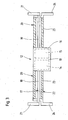
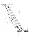
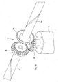
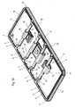
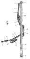
- Fig. 1 shows in a schematic perspective view of the support structure 2 of a bed 1.
- the support structure 2 is formed in the form of a slatted frame and provides a support surface 3, which serves to receive a mattress, a cushion element or the like.
- support structure 2 may be adjustable in height carried by a support frame, not shown, which in turn is on support rollers.
- the support structure 2 is itself formed as a slatted frame and has relatively mutually pivotally arranged sections 4, which are supported by a support frame 9.
- each subsection 4 consists of a frame 5.
- Each frame 5 in turn consists of frame parts 6, which are connected to one another by means of connectors 7.
- the slats 8 of the slatted frame are supported, the slats. 8 may be formed for example of wood, plastic or the like.
- the support frame 9 of the support structure 2 also consists of frame parts 10, which are interconnected by means of corresponding connector 11.
- both the frame parts 6 of the frame 5 and the frame parts 10 of the support frame 9 may be formed of aluminum, for example in the form of Aluminiumstrangpreß turnover.
- the frame parts 6 and 10 interconnecting connectors 7 and 11 are also made of aluminum. Likewise, it is possible to form the connectors 7 and 11, respectively, from plastic.
- the middle portion 4 that is, with respect to the leaf level Fig. 1 second section 4 from the left is fixedly connected to the holding frame 9.
- the front side of this section 4 is flanged on both sides of a closer to be described pivoting device 12 according to the invention.
- a second section 4 which can also be referred to as the head section.
- the serving as a head portion section 4 and serving as the middle section portion 4 are formed by means of the interposed pivoting device 12 relative to each other pivotable.
- each left side arranged portion 4 are arranged relative to this pivotally.
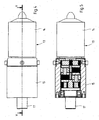
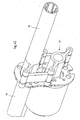
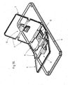
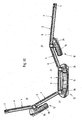
- Fig. 2 shows the support structure Fig. 1 in a schematic side view. Also from this representation, the individual sections 4 can be seen, which are formed relative to each other thanks to the respectively between two adjacent sections 4 respectively intermediate pivoting device 12.
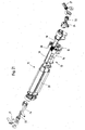
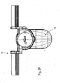
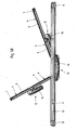
- a pivoting device 12 each have a drive device 13, which - as already on the basis of FIGS. 1 and 2 explained-frontally between two adjacent sections 4 is arranged.
- the drive means 13 comprises a motor 14 and a gear 15.
- the motor 14 and the gear 15 of the drive means 13 are housed in a housing 16, which is preferably formed in two parts and consists of plastic.
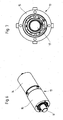
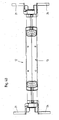
- a shaft 17 is flanged on the output side, according to the embodiment shown Fig. 3 is formed of two half-axes 18 and 19.
- the transmission 15 is arranged substantially centrally between the two half-axes 18 and 19.
- the half axles 18 and 19 each have a fastening flange 21 on one end, which serves to couple one of the two adjacent sections 4 with the pivoting device 12.
- the mounting flanges 21 are preferably formed as webs which can be inserted into the hollow frame parts 6 of a frame 5 of a section 4 and fastened there.
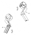
- the drive device 13 is how Fig. 3 further can be seen connected to a fixed support member 22.
- This support element 22 is formed from two sections 23, wherein the drive means 13 is arranged substantially centrally between the two sections 23.
- the subsections 23 preferably each form a housing 20, in which the respectively associated semiaxes 18 and 19 are arranged rotatably mounted.
- the subsections 23 each have an attachment flange 24 on one end, by means of which the swiveling device 12 can be arranged on a second subsection.
- the approach flanges 24 are preferably formed as web-shaped holder, which is inserted to arrange a portion 4 of the pivoting device 12 in the hollow frame parts of the associated frame 5 of the section 4 and can be fixed there.
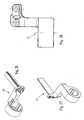
- the pivoting device 12 serves to connect two sections 4 relatively pivotable with each other.
- the attachment flanges 21 serve to arrange the first section 4, whereas the attachment flanges 24 are provided for the arrangement of the second section 4.
- the mounting flanges 21 pivot relative to the shoulder flanges 24, whereby the portion 4 supported by the mounting flanges 21 is pivoted relative to the portion 4 carried by the shoulder flanges 24.
- the pivoting device 12 as in Fig. 3 is shown, is arranged frontally between two adjacent faces 4, as from the FIGS. 1 and 2 seen. In this way, a particularly space-saving design of the entire bed construction is achieved. In addition, there is no need for additional linkage, as these are known from the prior art.
- the pivoting device 12 is designed splash-proof.
- An operation of the drive device 13 is preferably carried out by means of a remote control, which may be cable-based or radio-based.
- a remote control which may be cable-based or radio-based.
- FIGS. 4, to 20 a first embodiment
- FIGS. 21 to 36 a second embodiment
- FIGS. 37 to 43 a third embodiment
- the Fig. 44 a fourth embodiment
- the Fig. 45 a fifth embodiment
- the FIGS. 46 to 50 a sixth embodiment
- the FIGS. 51 to 60 relate to a further embodiment.
- Identical reference numbers identify identical and / or similar parts and / or elements.
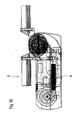
- Fig. 4 shows in a first embodiment, a drive device 13, which has a motor 14 and a transmission 15. Both the engine 14 and the transmission 15 are each housed in a housing.
- FIG. 5 A partially sectioned side view of the drive device 13 according to Fig. 4 along the section line VV to Fig. 4 , shows Fig. 5 , It is off Fig. 5 in particular, to recognize the structure of the transmission 15.
- FIG. 4 A perspective view of the drive device 13 according to Fig. 4 shows Fig. 6 , A side view of the drive device 13 after Fig. 4 , in the viewing direction with respect to the plane of the drawing Fig. 4 from the left is in Fig. 7 shown.
- Fig. 8 shows the drive device 13 in a detailed view Fig. 5 , wherein in particular the structure of the transmission 15 can be seen.
- the transmission 15 is a four-stage gear transmission.
- the transmission 15 comprises a ring gear 25 on the one hand and gear wheels 26 in engagement therewith on the other hand.
- the gears 26 form the transmission stages in a conventional manner.
- the ring gear 25 and the gears 26 are disposed within a transmission housing 27.
- a shaft 17 is provided which communicates with the gears 26 in a force-transmitting manner.
- the gear geometry of the transmission 15 is designed so that all gear stages have the same internal toothing.
- the ring gear 25 receives all components and serves as a housing.
- the geometry of the first three gear stages is identical.
- the sun gear profile is made by punching or lasering in the disk.
- the shaft is supported by means of an encapsulated rolling bearing 28 due to the following advantages: Low cost and small footprint; no axial forces and / or shear forces; extremely low output speed and the shaft 17 is additionally supported by the planetary gears.
- Fig. 9 shows in a perspective view the transmission 15 after Fig. 8 , In particular, the individual toothed wheels 26 as well as the toothed wheels separating from each other face plates 29 can be seen here.
- the ring gear 25 and an exemplary face plate 29 are shown in detail in the FIGS. 10, 11, 12 and 13 shown.
- FIG. 8 further reveals the gear 15 is closed by means of a motor 30 side cap 30.
- This cap 30 is in a detailed view in the FIGS. 14, 15 and 16 shown.
- Fig. 17 shows the to the transmission 15 after Fig. 8 flanged engine 14. It can be seen off Fig. 17 In particular, the formation of the motor-side pinion 31st
- FIGS. 18, 19 and 20 each show in a different view a planetary carrier 32, wherein the FIGS. 18 to 20 the planet carrier 32 of the last stage of the transmission 15 after Fig. 8 represent.
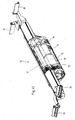
- Fig. 21 shows in exploded view a second embodiment of the invention, which differs from the embodiment according to the FIGS. 4 to 20 characterized in that a toothed belt is used as means for transmitting engine power.
- the timing belt itself is in Fig. 21 not shown.
- FIGS. 22, 23 . 24 and 25 shown.
- the with respect to the plane of the drawing Fig. 21 left mounting flange 21 is in a detailed view in the FIGS. 26, 27 and 28 played.
- connection part 33 For coupling the mounting flanges 21 to the respective associated half-axes 18 and 19 of the shaft 17 is used in the embodiment according to Fig. 21 a connection part 33, which in a detailed representation in the FIGS. 29, 30 . 31 and 32 is reproduced.
- the connecting part 33 consists of a pin-shaped extension 34 and a head 35.
- the head 35 carries circumferentially extending in the longitudinal direction ribs 36 which engage in the assembled state in a corresponding toothing of the respective associated mounting flanges 21, in particular Fig. 21 can be seen.
- a toothed belt gear 26, as in the embodiment according to Fig. 21 can be used as an example, is in the FIGS. 33, 34 . 35 and 36 shown.
- a third embodiment of the pivoting device 12 according to the invention show the FIGS. 37 to 43 .
- a motor 14 and a gear 15 are arranged in a housing 16, wherein the force deflection takes place on the shaft 17 by means of a gear arrangement 37.
- This gear assembly 37 is in a detailed view in Fig. 43 shown again.
- the gear assembly 37 consists of two gears 26, the front side engage with each other.
- FIG. 44 Another embodiment of the gear arrangement 37 shows Fig. 44 , which relates to a fourth embodiment of the invention.
- three bevel gears act together, each half axle 18 and 19 each end carries a bevel gear 38, which engage two bevel gears in a flanged on the gear 15 bevel gear 38.
- Fig. 45 shows a further embodiment of a gear arrangement 37 according to a fifth embodiment of the invention.
- a four-bar linkage in the form of a parallelogram is used for power transmission.
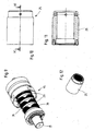
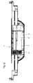
- a sixth embodiment of the invention is in the FIGS. 46 to 50 shown.
- the peculiarity of this embodiment results in particular from the compact design of the accommodated in the housing 16 drive means 13, in particular Fig. 50 recognize.
- the advantage of this embodiment is, in particular, that the drive device 13 with respect to the drawing plane after Fig. 50 down very little, which makes it possible in particular to use the pivoting device 12 according to the invention also for low-density beds.
- a spring 39 is provided which serves to provide a base load. The provision of such a spring allows advantageously, the entire drive means 13, that is, both the motor 14 and the gear 15 interpreted comparatively small dimensioned.
- the pivoting device according to the invention not only via a motor, but two motors, for example in the form of a double motor, has, which is especially in over-normal beds advantageous to provide the required adjustment can.
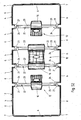
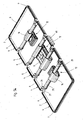
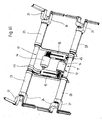
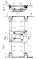
- FIGS. 51 to 60 Another embodiment is in the FIGS. 51 to 60 shown.
- a support structure 2 is also provided according to this embodiment, which consists of individual sections 4.
- the support structure 2 is supported by a holding frame 9 in the manner already described.
- the peculiarity of the embodiment according to the FIGS. 51 to 60 consists in the five relative to each other pivotally arranged sections 4, wherein three sections 4 are coupled to each other via a common pivoting device 12.
- the support structure 2 has a central portion 4, which is arranged in the final assembled state by means of two connecting rails 40 on the support frame 9, fixed, which means that the central portion 4 is not relative to the support frame 9 is pivotable.
- the middle section 4 sibling sections 4 are movable relative to the middle section 4.
- the to the movable sections 4 with respect to the plane of the drawing 51 On the right side or left side sibling sections 4 are in turn arranged to be movable to the movable sections 4. Due to this movable arrangement of the Subsections 4 resulting adjustment of the support structure 2, that is, the individual sections 4 relative to each other results, for example, from the FIGS. 55 . 56 and 58 to 60 , where the representation after Fig. 60 only the support structure 2, that does not show the support structure receiving the Auflagerkonstrutation in the final assembled state.
- FIGS. 61 to 68 show an embodiment of the invention, according to which at least with respect to a pivoting device 12, a double motor is used.
- a pivoting device 12 for which a double motor can be used, for example, the pivoting device 12 of a central portion 4, as exemplified in 51 shown.
- the pivoting device 12 has two motors 14. Each motor 14 is connected to an associated gear 15th flanged, which in turn is force-transmitting with an associated shaft 17 in conjunction.
- gear 15th flanged For power transmission between the transmission 15 on the one hand and shaft 17 on the other hand serves as a Gelenkkhebel 45th
- FIGS. 65 and 66 or 67 and 68 show a shoulder flange 24 and a mounting flange 21, respectively.
- the approach flange 24 has a connecting portion 42 which is placed in the final assembled state on the portion 23 of a support member 22, in particular Fig. 61 recognize.
- the approach flange 24 further has an angle part 43. This engages in the final assembled state in a hollow frame part 6 of a section 4, as already explained above.
- the mounting flange 21 has an angle portion 44, as from the FIGS. 67 and 68 seen.
Landscapes
- Health & Medical Sciences (AREA)
- Nursing (AREA)
- General Health & Medical Sciences (AREA)
- Life Sciences & Earth Sciences (AREA)
- Animal Behavior & Ethology (AREA)
- Public Health (AREA)
- Veterinary Medicine (AREA)
- Invalid Beds And Related Equipment (AREA)
- Chairs For Special Purposes, Such As Reclining Chairs (AREA)
Claims (7)
- Lit (1), notamment lit de malade et/ou lit de soins, comprenant une construction d'appui (2) fournissant une surface d'appui (3) destinée à un matelas, un élément de rembourrage ou similaire, la construction d'appui (2) étant formée de sections (4) qui sont disposées de manière pivotante l'une par rapport à l'autre, un dispositif de pivotement (12) étant respectivement disposé entre deux sections (4) adjacentes,
caractérisé en ce
que le dispositif de pivotement (12) comprend un dispositif d'entraînement électronique (13), lequel dispositif d'entraînement (13) comprend, quant à lui, un moteur (14) et une transmission (15), que le dispositif de pivotement (12) comprend un arbre (17) fixé par bride à la transmission (15) du dispositif d'entraînement (13), lequel arbre (17) est formé par deux demi-axes (18, 19), les demi-axes (18, 19) étant chacun logés dans un boîtier (20), et que le dispositif de pivotement (12) comprend un élément de support (22) composé de deux sections (23), les deux sections (23) étant chacune formée par le boîtier (20) recevant le demi-axe respectif (18, 19). - Lit (1) selon la revendication 1, caractérisé en ce que les demi-axes (18, 19) portent chacun une bride de fixation (21) à une extrémité, les brides de fixation (21) servant à disposer une première section (4) sur le dispositif de pivotement (12).
- Lit (1) selon la revendication 2, caractérisé en ce que les sections (22) portent chacune une bride de liaison (24) à une extrémité, les brides de liaison (24) servant à disposer une deuxième section (4) sur le dispositif de pivotement (12).
- Lit (1) selon la revendication 1, caractérisé en ce que chaque section (4) est formée par un cadre (5), lequel cadre (5) est composé des éléments de cadre creux (6).
- Lit (1) selon l'une des revendications précédentes 1 à 4, caractérisé en ce que les brides de fixation (21) et les brides de liaison (24) sont conçus comme des éléments de retenue en forme d'entretoise qui sont insérés dans les éléments de cadre creux (6) du cadre associé (5) de la section (4) et y sont fixés pour disposer une section (4) sur le dispositif de pivotement (12).
- Lit (1) selon la revendication 1, caractérisé en ce que l'une des sections (4) reliées au dispositif de pivotement (12) est disposée sur le dispositif de pivotement (12) de manière relativement déplaçable dans une direction transversale à l'extension longitudinale des demi-axes (18, 19) du dispositif de pivotement (12).
- Lit (1) selon la revendication 1, caractérisé en ce que le dispositif d'entraînement (13) comprend un boîtier (16) qui reçoit le moteur (14) et la transmission (15).
Applications Claiming Priority (3)
| Application Number | Priority Date | Filing Date | Title |
|---|---|---|---|
| DE200620008523 DE202006008523U1 (de) | 2006-05-26 | 2006-05-26 | Verschwenkeinrichtung |
| DE202006018156U DE202006018156U1 (de) | 2006-05-26 | 2006-11-28 | Verschwenkeinrichtung |
| PCT/EP2007/004032 WO2007137678A1 (fr) | 2006-05-26 | 2007-05-08 | Dispositif à basculement |
Publications (2)
| Publication Number | Publication Date |
|---|---|
| EP2020977A1 EP2020977A1 (fr) | 2009-02-11 |
| EP2020977B1 true EP2020977B1 (fr) | 2014-11-12 |
Family
ID=37833120
Family Applications (1)
| Application Number | Title | Priority Date | Filing Date |
|---|---|---|---|
| EP07724956.3A Not-in-force EP2020977B1 (fr) | 2006-05-26 | 2007-05-08 | Lit avec un dispositif à basculement |
Country Status (14)
| Country | Link |
|---|---|
| US (1) | US8312579B2 (fr) |
| EP (1) | EP2020977B1 (fr) |
| JP (1) | JP2009538163A (fr) |
| KR (1) | KR101309941B1 (fr) |
| CN (1) | CN101489515B (fr) |
| AU (1) | AU2007267476B2 (fr) |
| BR (1) | BRPI0712480A2 (fr) |
| CA (1) | CA2653353C (fr) |
| DE (1) | DE202006018156U1 (fr) |
| MX (1) | MX2008015052A (fr) |
| NO (1) | NO20085048L (fr) |
| NZ (1) | NZ573364A (fr) |
| RU (1) | RU2443405C2 (fr) |
| WO (1) | WO2007137678A1 (fr) |
Cited By (1)
| Publication number | Priority date | Publication date | Assignee | Title |
|---|---|---|---|---|
| DE202022103498U1 (de) | 2022-06-23 | 2023-10-10 | Hermann Bock Gmbh | Bett mit einer Hubeinrichtung |
Families Citing this family (28)
| Publication number | Priority date | Publication date | Assignee | Title |
|---|---|---|---|---|
| US9744087B2 (en) | 2005-02-22 | 2017-08-29 | Roger P. Jackson | Patient support apparatus with body slide position digitally coordinated with hinge angle |
| US9295433B2 (en) | 2005-02-22 | 2016-03-29 | Roger P. Jackson | Synchronized patient elevation and positioning apparatus for use with patient positioning support systems |
| US7739762B2 (en) | 2007-10-22 | 2010-06-22 | Mizuho Orthopedic Systems, Inc. | Surgery table apparatus |
| US7565708B2 (en) | 2005-02-22 | 2009-07-28 | Jackson Roger P | Patient positioning support structure |
| US20150059094A1 (en) | 2005-02-22 | 2015-03-05 | Roger P. Jackson | Patient positioning support structure |
| US9186291B2 (en) | 2005-02-22 | 2015-11-17 | Roger P. Jackson | Patient positioning support structure with trunk translator |
| US10869798B2 (en) | 2006-05-05 | 2020-12-22 | Warsaw Orthopedic, Inc. | Patient positioning support apparatus with virtual pivot-shift pelvic pads, upper body stabilization and fail-safe table attachment mechanism |
| DE202008008191U1 (de) | 2008-06-18 | 2008-09-18 | Bock, Klaus | Antriebssystem |
| DE202008016896U1 (de) | 2008-12-19 | 2009-03-05 | Spiroplex Gmbh | Liegeflächeneinrichtung für ein Bett |
| DE102008064096B4 (de) | 2008-12-19 | 2010-09-02 | Klaus Bock | Liegeflächeneinrichtung für ein Bett |
| JP5493742B2 (ja) * | 2009-11-12 | 2014-05-14 | アイシン精機株式会社 | 可動寝いす |
| US8640284B2 (en) * | 2011-03-17 | 2014-02-04 | Jaume Casteras Farre | Articulated and/or jointed bed |
| DE202011100577U1 (de) * | 2011-05-12 | 2012-08-13 | Grass Gmbh | Möbelbeschlag für ein bewegbares Möbelteil und Möbel |
| WO2013058806A1 (fr) | 2011-10-17 | 2013-04-25 | Jackson Roger P | Structure de support de positionnement de patient |
| US9561145B2 (en) | 2012-02-07 | 2017-02-07 | Roger P. Jackson | Fail-safe release mechanism for use with patient positioning support apparati |
| CN102824254B (zh) * | 2012-09-14 | 2014-05-14 | 天津科技大学 | 一种辅助护理移乘装置 |
| US9402775B2 (en) | 2014-07-07 | 2016-08-02 | Roger P. Jackson | Single and dual column patient positioning and support structure |
| US9622928B2 (en) | 2014-07-07 | 2017-04-18 | Roger P. Jackson | Radiolucent hinge for a surgical table |
| CA2969261A1 (fr) * | 2015-11-06 | 2017-05-11 | Shanghai Sincol Furniture Products Co., Ltd. | Matelas electrique |
| US10506884B2 (en) * | 2016-02-24 | 2019-12-17 | Dreamwell, Ltd. | Adjustable foundation |
| US10813807B2 (en) * | 2016-06-29 | 2020-10-27 | Stryker Corporation | Patient support systems with hollow rotary actuators |
| US10765575B2 (en) | 2016-06-29 | 2020-09-08 | Stryker Corporation | Patient support systems with rotary actuators comprising rotation limiting devices |
| US10864128B2 (en) | 2016-06-29 | 2020-12-15 | Stryker Corporation | Patient support systems with rotary actuators having cycloidal drives |
| CN107928911A (zh) * | 2017-12-05 | 2018-04-20 | 张艳艳 | 一种多功能医疗床 |
| BR112021004924A2 (pt) * | 2018-09-17 | 2021-06-01 | Ergomotion, Inc. | conjunto articulado para uma cama ajustável |
| CN109368542A (zh) * | 2018-12-12 | 2019-02-22 | 常州工学院 | 一种高度自动控制装置及方法 |
| US20230346130A1 (en) * | 2020-06-03 | 2023-11-02 | Polyron Zikim Ach Ltd | Adjustable mattress frame and a method for adjusting the frame |
| TWI803397B (zh) * | 2022-07-21 | 2023-05-21 | 施權航 | 電動床 |
Family Cites Families (18)
| Publication number | Priority date | Publication date | Assignee | Title |
|---|---|---|---|---|
| EP0408636A4 (en) * | 1988-03-23 | 1992-01-02 | Robert Ferrand | Patient support system |
| US5063623A (en) * | 1990-10-15 | 1991-11-12 | Bathrick Leeland M | Power module for an ariculated bed |
| JPH0555937U (ja) * | 1992-01-06 | 1993-07-27 | 株式会社タカラユニオン | 背もたれの起伏装置 |
| FR2724882B1 (fr) * | 1994-09-23 | 1997-01-10 | Faure Bertrand Equipements Sa | Armature tubulaire pour siege d'automobile |
| US5711577A (en) * | 1995-12-01 | 1998-01-27 | Fisher Dynamics Corporation | Pivot assembly for a structured vehicle seat |
| US5926877A (en) * | 1997-10-23 | 1999-07-27 | Lin; Joe | Adjustable supporting table |
| DE29802384U1 (de) | 1998-02-12 | 1998-04-09 | Recticel Int Bettsysteme Gmbh | Sitz-/Liegemöbel, insbesondere Lattenrost, mit verstellbaren Elementen |
| US6058532A (en) * | 1998-03-30 | 2000-05-09 | Allen; Newton P. | Apparatus for elevating one end portion of a bed frame |
| RU2265764C2 (ru) * | 1999-07-12 | 2005-12-10 | Лук Ламеллен Унд Купплюнгсбау Бетайлигунгс Кг | Привод |
| EP1217922B1 (fr) | 1999-09-02 | 2004-07-28 | Linak A/S | Dispositif de commande, specialement conccu pour des meubles reglables, notamment des lits et des sommiers de lit |
| RU2200448C2 (ru) | 2000-12-14 | 2003-03-20 | Общество с ограниченной ответственностью "Арсен" | Трансформируемая мягкая мебель для сидения и лежания и поворотное устройство спинки трансформируемой мягкой мебели |
| GB0100981D0 (en) | 2001-01-13 | 2001-02-28 | Smiths Group Plc | Surgical tables |
| DE20308887U1 (de) * | 2003-06-05 | 2004-10-07 | Cimosys Ag | Motorisch verstellbare Stützeinrichtung für eine Polsterung eines Sitz- und/oder Liegemöbels |
| US7395568B2 (en) * | 2003-09-12 | 2008-07-08 | Dreamwell, Ltd. | Self-contained articulated mattress |
| RU2261695C2 (ru) * | 2003-09-22 | 2005-10-10 | Царёв Илья Львович | Кровать функциональная (варианты) |
| US6893092B1 (en) * | 2003-11-20 | 2005-05-17 | Fisher Dynamics Corporation | Inertia increasing vehicle seat adjustment mechanism |
| DE202004018913U1 (de) | 2004-04-01 | 2005-08-11 | Cimosys Ag | Baukastensystem zur Montage motorisch verstellbarer Stützeinrichtungen für Polsterungen von Sitz- und/oder Liegemöbeln |
| US7118171B2 (en) * | 2004-05-05 | 2006-10-10 | Lear Corporation | Seat assembly with folding head restraint and method for folding same |
-
2006
- 2006-11-28 DE DE202006018156U patent/DE202006018156U1/de not_active Expired - Lifetime
-
2007
- 2007-05-08 AU AU2007267476A patent/AU2007267476B2/en not_active Ceased
- 2007-05-08 KR KR1020087031437A patent/KR101309941B1/ko not_active IP Right Cessation
- 2007-05-08 WO PCT/EP2007/004032 patent/WO2007137678A1/fr active Application Filing
- 2007-05-08 BR BRPI0712480-5A patent/BRPI0712480A2/pt not_active IP Right Cessation
- 2007-05-08 CN CN2007800269571A patent/CN101489515B/zh not_active Expired - Fee Related
- 2007-05-08 MX MX2008015052A patent/MX2008015052A/es active IP Right Grant
- 2007-05-08 EP EP07724956.3A patent/EP2020977B1/fr not_active Not-in-force
- 2007-05-08 US US12/227,745 patent/US8312579B2/en not_active Expired - Fee Related
- 2007-05-08 NZ NZ573364A patent/NZ573364A/en not_active IP Right Cessation
- 2007-05-08 CA CA2653353A patent/CA2653353C/fr not_active Expired - Fee Related
- 2007-05-08 JP JP2009511359A patent/JP2009538163A/ja active Pending
- 2007-05-08 RU RU2008151373/12A patent/RU2443405C2/ru not_active IP Right Cessation
-
2008
- 2008-12-04 NO NO20085048A patent/NO20085048L/no not_active Application Discontinuation
Cited By (1)
| Publication number | Priority date | Publication date | Assignee | Title |
|---|---|---|---|---|
| DE202022103498U1 (de) | 2022-06-23 | 2023-10-10 | Hermann Bock Gmbh | Bett mit einer Hubeinrichtung |
Also Published As
| Publication number | Publication date |
|---|---|
| AU2007267476A1 (en) | 2007-12-06 |
| RU2008151373A (ru) | 2010-07-10 |
| KR101309941B1 (ko) | 2013-09-17 |
| CN101489515B (zh) | 2012-08-08 |
| AU2007267476B2 (en) | 2012-07-12 |
| CA2653353C (fr) | 2013-12-17 |
| MX2008015052A (es) | 2009-01-26 |
| WO2007137678A1 (fr) | 2007-12-06 |
| NZ573364A (en) | 2011-11-25 |
| CA2653353A1 (fr) | 2007-12-06 |
| BRPI0712480A2 (pt) | 2012-08-28 |
| CN101489515A (zh) | 2009-07-22 |
| NO20085048L (no) | 2009-02-06 |
| US20090235456A1 (en) | 2009-09-24 |
| JP2009538163A (ja) | 2009-11-05 |
| EP2020977A1 (fr) | 2009-02-11 |
| DE202006018156U1 (de) | 2007-02-22 |
| US8312579B2 (en) | 2012-11-20 |
| KR20090021186A (ko) | 2009-02-27 |
| RU2443405C2 (ru) | 2012-02-27 |
Similar Documents
| Publication | Publication Date | Title |
|---|---|---|
| EP2020977B1 (fr) | Lit avec un dispositif à basculement | |
| EP1239755B1 (fr) | Support reglable par moteur et destine au rembourrage d'un siege et/ou d'un meuble destine a s'allonger, par exemple d'un matelas ou d'un lit | |
| EP1276406B1 (fr) | Dispositif d'appui à réglage motorisé destiné au rembourrage d'un fauteuil et/ou d'un meuble de couchage | |
| EP2792277B1 (fr) | Entraînement de meuble à moteur électrique | |
| DE60012551T2 (de) | Drehantrieb, insbesondere für verstellbare möbel, wie betten und bettbodens | |
| EP2418984B1 (fr) | Dispositif de support réglable par moteur électrique | |
| EP2418981B1 (fr) | Dispositif de support réglable par moteur électrique | |
| EP1708595B1 (fr) | Entrainement de meuble servant a ajuster une premiere partie d'un meuble par rapport a une deuxieme partie de ce meuble | |
| WO2004006725A1 (fr) | Dispositif de reglage et dispositif de support reglable pour lits, matelas, sieges et analogues | |
| EP1603433A1 (fr) | Systeme modulaire pour le montage de dispositifs de soutien, pouvant etre deplaces au moyen d'un moteur, destines au rembourrage de meubles d'assise et/ou couchage | |
| EP2418983B1 (fr) | Dispositif de soutien réglable au moyen d'un moteur électrique | |
| EP2418982B1 (fr) | Dispositif de soutien réglable au moyen un moteur électrique | |
| EP0794358A2 (fr) | Dispositif de réglage électrique pour meubles | |
| EP1416832B2 (fr) | Entrainement de meuble destine a deplacer des elements d'un meuble les uns par rapport aux autres | |
| EP0935937B1 (fr) | Sommier à lattes avec partie de tête- et pied réglables d'une meuble d'assise ou de chouchage | |
| EP2856916B1 (fr) | Agencement d'actionneur pour un meuble réglable destiné à s'asseoir ou à s'allonger ainsi que meuble réglable destinée à s'asseoir ou à s'allonger | |
| DE202006008523U1 (de) | Verschwenkeinrichtung | |
| WO2014040728A1 (fr) | Entraînement de meuble à moteur électrique | |
| EP4360506A1 (fr) | Sommier à lattes | |
| EP1414325A1 (fr) | Entrainement electromoteur pour meuble servant a deplacer des parties d'un meuble les unes par rapport aux autres | |
| DE102009036402A1 (de) | Antriebsvorrichtung für Sitz- und Liegemöbel | |
| DE102009007149A1 (de) | Antriebssystem für Möbelbauteile |
Legal Events
| Date | Code | Title | Description |
|---|---|---|---|
| PUAI | Public reference made under article 153(3) epc to a published international application that has entered the european phase |
Free format text: ORIGINAL CODE: 0009012 |
|
| 17P | Request for examination filed |
Effective date: 20081201 |
|
| AK | Designated contracting states |
Kind code of ref document: A1 Designated state(s): AT BE BG CH CY CZ DE DK EE ES FI FR GB GR HU IE IS IT LI LT LU LV MC MT NL PL PT RO SE SI SK TR |
|
| AX | Request for extension of the european patent |
Extension state: AL BA HR MK RS |
|
| 17Q | First examination report despatched |
Effective date: 20090403 |
|
| RAP1 | Party data changed (applicant data changed or rights of an application transferred) |
Owner name: HERMANN BOCK GMBH |
|
| RIN1 | Information on inventor provided before grant (corrected) |
Inventor name: BOCK, KLAUS |
|
| DAX | Request for extension of the european patent (deleted) | ||
| GRAP | Despatch of communication of intention to grant a patent |
Free format text: ORIGINAL CODE: EPIDOSNIGR1 |
|
| INTG | Intention to grant announced |
Effective date: 20140616 |
|
| RIN1 | Information on inventor provided before grant (corrected) |
Inventor name: BOCK, KLAUS |
|
| GRAS | Grant fee paid |
Free format text: ORIGINAL CODE: EPIDOSNIGR3 |
|
| GRAA | (expected) grant |
Free format text: ORIGINAL CODE: 0009210 |
|
| AK | Designated contracting states |
Kind code of ref document: B1 Designated state(s): AT BE BG CH CY CZ DE DK EE ES FI FR GB GR HU IE IS IT LI LT LU LV MC MT NL PL PT RO SE SI SK TR |
|
| REG | Reference to a national code |
Ref country code: GB Ref legal event code: FG4D Free format text: NOT ENGLISH |
|
| REG | Reference to a national code |
Ref country code: CH Ref legal event code: EP |
|
| REG | Reference to a national code |
Ref country code: AT Ref legal event code: REF Ref document number: 695296 Country of ref document: AT Kind code of ref document: T Effective date: 20141115 |
|
| REG | Reference to a national code |
Ref country code: IE Ref legal event code: FG4D Free format text: LANGUAGE OF EP DOCUMENT: GERMAN |
|
| REG | Reference to a national code |
Ref country code: DE Ref legal event code: R096 Ref document number: 502007013566 Country of ref document: DE Effective date: 20150108 |
|
| REG | Reference to a national code |
Ref country code: NL Ref legal event code: VDEP Effective date: 20141112 |
|
| PG25 | Lapsed in a contracting state [announced via postgrant information from national office to epo] |
Ref country code: NL Free format text: LAPSE BECAUSE OF FAILURE TO SUBMIT A TRANSLATION OF THE DESCRIPTION OR TO PAY THE FEE WITHIN THE PRESCRIBED TIME-LIMIT Effective date: 20141112 Ref country code: IS Free format text: LAPSE BECAUSE OF FAILURE TO SUBMIT A TRANSLATION OF THE DESCRIPTION OR TO PAY THE FEE WITHIN THE PRESCRIBED TIME-LIMIT Effective date: 20150312 Ref country code: ES Free format text: LAPSE BECAUSE OF FAILURE TO SUBMIT A TRANSLATION OF THE DESCRIPTION OR TO PAY THE FEE WITHIN THE PRESCRIBED TIME-LIMIT Effective date: 20141112 Ref country code: PT Free format text: LAPSE BECAUSE OF FAILURE TO SUBMIT A TRANSLATION OF THE DESCRIPTION OR TO PAY THE FEE WITHIN THE PRESCRIBED TIME-LIMIT Effective date: 20150312 Ref country code: LT Free format text: LAPSE BECAUSE OF FAILURE TO SUBMIT A TRANSLATION OF THE DESCRIPTION OR TO PAY THE FEE WITHIN THE PRESCRIBED TIME-LIMIT Effective date: 20141112 Ref country code: FI Free format text: LAPSE BECAUSE OF FAILURE TO SUBMIT A TRANSLATION OF THE DESCRIPTION OR TO PAY THE FEE WITHIN THE PRESCRIBED TIME-LIMIT Effective date: 20141112 |
|
| PG25 | Lapsed in a contracting state [announced via postgrant information from national office to epo] |
Ref country code: GR Free format text: LAPSE BECAUSE OF FAILURE TO SUBMIT A TRANSLATION OF THE DESCRIPTION OR TO PAY THE FEE WITHIN THE PRESCRIBED TIME-LIMIT Effective date: 20150213 Ref country code: PL Free format text: LAPSE BECAUSE OF FAILURE TO SUBMIT A TRANSLATION OF THE DESCRIPTION OR TO PAY THE FEE WITHIN THE PRESCRIBED TIME-LIMIT Effective date: 20141112 Ref country code: CY Free format text: LAPSE BECAUSE OF FAILURE TO SUBMIT A TRANSLATION OF THE DESCRIPTION OR TO PAY THE FEE WITHIN THE PRESCRIBED TIME-LIMIT Effective date: 20141112 Ref country code: LV Free format text: LAPSE BECAUSE OF FAILURE TO SUBMIT A TRANSLATION OF THE DESCRIPTION OR TO PAY THE FEE WITHIN THE PRESCRIBED TIME-LIMIT Effective date: 20141112 Ref country code: SE Free format text: LAPSE BECAUSE OF FAILURE TO SUBMIT A TRANSLATION OF THE DESCRIPTION OR TO PAY THE FEE WITHIN THE PRESCRIBED TIME-LIMIT Effective date: 20141112 |
|
| PG25 | Lapsed in a contracting state [announced via postgrant information from national office to epo] |
Ref country code: CZ Free format text: LAPSE BECAUSE OF FAILURE TO SUBMIT A TRANSLATION OF THE DESCRIPTION OR TO PAY THE FEE WITHIN THE PRESCRIBED TIME-LIMIT Effective date: 20141112 Ref country code: SK Free format text: LAPSE BECAUSE OF FAILURE TO SUBMIT A TRANSLATION OF THE DESCRIPTION OR TO PAY THE FEE WITHIN THE PRESCRIBED TIME-LIMIT Effective date: 20141112 Ref country code: EE Free format text: LAPSE BECAUSE OF FAILURE TO SUBMIT A TRANSLATION OF THE DESCRIPTION OR TO PAY THE FEE WITHIN THE PRESCRIBED TIME-LIMIT Effective date: 20141112 Ref country code: DK Free format text: LAPSE BECAUSE OF FAILURE TO SUBMIT A TRANSLATION OF THE DESCRIPTION OR TO PAY THE FEE WITHIN THE PRESCRIBED TIME-LIMIT Effective date: 20141112 Ref country code: RO Free format text: LAPSE BECAUSE OF FAILURE TO SUBMIT A TRANSLATION OF THE DESCRIPTION OR TO PAY THE FEE WITHIN THE PRESCRIBED TIME-LIMIT Effective date: 20141112 |
|
| PGFP | Annual fee paid to national office [announced via postgrant information from national office to epo] |
Ref country code: DE Payment date: 20150515 Year of fee payment: 9 |
|
| REG | Reference to a national code |
Ref country code: DE Ref legal event code: R097 Ref document number: 502007013566 Country of ref document: DE |
|
| PLBE | No opposition filed within time limit |
Free format text: ORIGINAL CODE: 0009261 |
|
| STAA | Information on the status of an ep patent application or granted ep patent |
Free format text: STATUS: NO OPPOSITION FILED WITHIN TIME LIMIT |
|
| 26N | No opposition filed |
Effective date: 20150813 |
|
| PG25 | Lapsed in a contracting state [announced via postgrant information from national office to epo] |
Ref country code: IT Free format text: LAPSE BECAUSE OF FAILURE TO SUBMIT A TRANSLATION OF THE DESCRIPTION OR TO PAY THE FEE WITHIN THE PRESCRIBED TIME-LIMIT Effective date: 20141112 |
|
| REG | Reference to a national code |
Ref country code: CH Ref legal event code: PL |
|
| GBPC | Gb: european patent ceased through non-payment of renewal fee |
Effective date: 20150508 |
|
| PG25 | Lapsed in a contracting state [announced via postgrant information from national office to epo] |
Ref country code: CH Free format text: LAPSE BECAUSE OF NON-PAYMENT OF DUE FEES Effective date: 20150531 Ref country code: LU Free format text: LAPSE BECAUSE OF FAILURE TO SUBMIT A TRANSLATION OF THE DESCRIPTION OR TO PAY THE FEE WITHIN THE PRESCRIBED TIME-LIMIT Effective date: 20150508 Ref country code: MC Free format text: LAPSE BECAUSE OF FAILURE TO SUBMIT A TRANSLATION OF THE DESCRIPTION OR TO PAY THE FEE WITHIN THE PRESCRIBED TIME-LIMIT Effective date: 20141112 Ref country code: LI Free format text: LAPSE BECAUSE OF NON-PAYMENT OF DUE FEES Effective date: 20150531 |
|
| REG | Reference to a national code |
Ref country code: IE Ref legal event code: MM4A |
|
| REG | Reference to a national code |
Ref country code: FR Ref legal event code: ST Effective date: 20160129 |
|
| PG25 | Lapsed in a contracting state [announced via postgrant information from national office to epo] |
Ref country code: SI Free format text: LAPSE BECAUSE OF FAILURE TO SUBMIT A TRANSLATION OF THE DESCRIPTION OR TO PAY THE FEE WITHIN THE PRESCRIBED TIME-LIMIT Effective date: 20141112 |
|
| PG25 | Lapsed in a contracting state [announced via postgrant information from national office to epo] |
Ref country code: GB Free format text: LAPSE BECAUSE OF NON-PAYMENT OF DUE FEES Effective date: 20150508 Ref country code: IE Free format text: LAPSE BECAUSE OF NON-PAYMENT OF DUE FEES Effective date: 20150508 |
|
| PG25 | Lapsed in a contracting state [announced via postgrant information from national office to epo] |
Ref country code: FR Free format text: LAPSE BECAUSE OF NON-PAYMENT OF DUE FEES Effective date: 20150601 |
|
| REG | Reference to a national code |
Ref country code: AT Ref legal event code: MM01 Ref document number: 695296 Country of ref document: AT Kind code of ref document: T Effective date: 20150508 |
|
| PG25 | Lapsed in a contracting state [announced via postgrant information from national office to epo] |
Ref country code: AT Free format text: LAPSE BECAUSE OF NON-PAYMENT OF DUE FEES Effective date: 20150508 |
|
| REG | Reference to a national code |
Ref country code: DE Ref legal event code: R119 Ref document number: 502007013566 Country of ref document: DE |
|
| PG25 | Lapsed in a contracting state [announced via postgrant information from national office to epo] |
Ref country code: MT Free format text: LAPSE BECAUSE OF FAILURE TO SUBMIT A TRANSLATION OF THE DESCRIPTION OR TO PAY THE FEE WITHIN THE PRESCRIBED TIME-LIMIT Effective date: 20141112 |
|
| PG25 | Lapsed in a contracting state [announced via postgrant information from national office to epo] |
Ref country code: DE Free format text: LAPSE BECAUSE OF NON-PAYMENT OF DUE FEES Effective date: 20161201 |
|
| PG25 | Lapsed in a contracting state [announced via postgrant information from national office to epo] |
Ref country code: BG Free format text: LAPSE BECAUSE OF FAILURE TO SUBMIT A TRANSLATION OF THE DESCRIPTION OR TO PAY THE FEE WITHIN THE PRESCRIBED TIME-LIMIT Effective date: 20141112 Ref country code: HU Free format text: LAPSE BECAUSE OF FAILURE TO SUBMIT A TRANSLATION OF THE DESCRIPTION OR TO PAY THE FEE WITHIN THE PRESCRIBED TIME-LIMIT; INVALID AB INITIO Effective date: 20070508 |
|
| PG25 | Lapsed in a contracting state [announced via postgrant information from national office to epo] |
Ref country code: BE Free format text: LAPSE BECAUSE OF NON-PAYMENT OF DUE FEES Effective date: 20150531 |
|
| PG25 | Lapsed in a contracting state [announced via postgrant information from national office to epo] |
Ref country code: TR Free format text: LAPSE BECAUSE OF FAILURE TO SUBMIT A TRANSLATION OF THE DESCRIPTION OR TO PAY THE FEE WITHIN THE PRESCRIBED TIME-LIMIT Effective date: 20141112 |
|
| P01 | Opt-out of the competence of the unified patent court (upc) registered |
Effective date: 20230522 |