EP2020591A2 - Appareil de mesure de déplacement - Google Patents
Appareil de mesure de déplacement Download PDFInfo
- Publication number
- EP2020591A2 EP2020591A2 EP08012121A EP08012121A EP2020591A2 EP 2020591 A2 EP2020591 A2 EP 2020591A2 EP 08012121 A EP08012121 A EP 08012121A EP 08012121 A EP08012121 A EP 08012121A EP 2020591 A2 EP2020591 A2 EP 2020591A2
- Authority
- EP
- European Patent Office
- Prior art keywords
- magnetic
- diffraction grating
- measuring apparatus
- displacement measuring
- composite scale
- Prior art date
- Legal status (The legal status is an assumption and is not a legal conclusion. Google has not performed a legal analysis and makes no representation as to the accuracy of the status listed.)
- Withdrawn
Links
- 238000006073 displacement reaction Methods 0.000 title claims abstract description 77
- 238000001514 detection method Methods 0.000 claims abstract description 75
- 239000002131 composite material Substances 0.000 claims abstract description 59
- 230000003287 optical effect Effects 0.000 claims abstract description 34
- 230000001678 irradiating effect Effects 0.000 claims abstract description 5
- 229920005989 resin Polymers 0.000 claims description 65
- 239000011347 resin Substances 0.000 claims description 65
- 239000000463 material Substances 0.000 claims description 39
- 230000001681 protective effect Effects 0.000 claims description 14
- 229920001187 thermosetting polymer Polymers 0.000 claims description 6
- 238000005259 measurement Methods 0.000 description 28
- 238000000034 method Methods 0.000 description 10
- 238000004519 manufacturing process Methods 0.000 description 8
- 230000004044 response Effects 0.000 description 8
- 230000008569 process Effects 0.000 description 6
- 239000011651 chromium Substances 0.000 description 5
- 238000012545 processing Methods 0.000 description 4
- VYZAMTAEIAYCRO-UHFFFAOYSA-N Chromium Chemical compound [Cr] VYZAMTAEIAYCRO-UHFFFAOYSA-N 0.000 description 3
- 229910052804 chromium Inorganic materials 0.000 description 3
- 230000001427 coherent effect Effects 0.000 description 3
- 238000000151 deposition Methods 0.000 description 3
- 238000000691 measurement method Methods 0.000 description 3
- 229920000515 polycarbonate Polymers 0.000 description 3
- 239000004417 polycarbonate Substances 0.000 description 3
- XEEYBQQBJWHFJM-UHFFFAOYSA-N Iron Chemical compound [Fe] XEEYBQQBJWHFJM-UHFFFAOYSA-N 0.000 description 2
- 229910052782 aluminium Inorganic materials 0.000 description 2
- XAGFODPZIPBFFR-UHFFFAOYSA-N aluminium Chemical compound [Al] XAGFODPZIPBFFR-UHFFFAOYSA-N 0.000 description 2
- 238000011109 contamination Methods 0.000 description 2
- 230000003247 decreasing effect Effects 0.000 description 2
- 238000010586 diagram Methods 0.000 description 2
- 239000003822 epoxy resin Substances 0.000 description 2
- 230000008020 evaporation Effects 0.000 description 2
- 238000001704 evaporation Methods 0.000 description 2
- 239000011521 glass Substances 0.000 description 2
- 239000000696 magnetic material Substances 0.000 description 2
- 229910052751 metal Inorganic materials 0.000 description 2
- 239000002184 metal Substances 0.000 description 2
- 238000012986 modification Methods 0.000 description 2
- 230000004048 modification Effects 0.000 description 2
- BASFCYQUMIYNBI-UHFFFAOYSA-N platinum Chemical compound [Pt] BASFCYQUMIYNBI-UHFFFAOYSA-N 0.000 description 2
- 229920000647 polyepoxide Polymers 0.000 description 2
- 229920000139 polyethylene terephthalate Polymers 0.000 description 2
- 239000005020 polyethylene terephthalate Substances 0.000 description 2
- 238000003825 pressing Methods 0.000 description 2
- 238000004544 sputter deposition Methods 0.000 description 2
- 239000012780 transparent material Substances 0.000 description 2
- VYPSYNLAJGMNEJ-UHFFFAOYSA-N Silicium dioxide Chemical compound O=[Si]=O VYPSYNLAJGMNEJ-UHFFFAOYSA-N 0.000 description 1
- 239000000853 adhesive Substances 0.000 description 1
- 230000004075 alteration Effects 0.000 description 1
- 238000013459 approach Methods 0.000 description 1
- 239000011248 coating agent Substances 0.000 description 1
- 238000000576 coating method Methods 0.000 description 1
- 229910017052 cobalt Inorganic materials 0.000 description 1
- 239000010941 cobalt Substances 0.000 description 1
- GUTLYIVDDKVIGB-UHFFFAOYSA-N cobalt atom Chemical compound [Co] GUTLYIVDDKVIGB-UHFFFAOYSA-N 0.000 description 1
- 150000001875 compounds Chemical class 0.000 description 1
- 230000003111 delayed effect Effects 0.000 description 1
- 238000013461 design Methods 0.000 description 1
- 230000000694 effects Effects 0.000 description 1
- PCHJSUWPFVWCPO-UHFFFAOYSA-N gold Chemical compound [Au] PCHJSUWPFVWCPO-UHFFFAOYSA-N 0.000 description 1
- 229910052737 gold Inorganic materials 0.000 description 1
- 239000010931 gold Substances 0.000 description 1
- 238000010438 heat treatment Methods 0.000 description 1
- 229910052742 iron Inorganic materials 0.000 description 1
- 150000002739 metals Chemical class 0.000 description 1
- 238000004806 packaging method and process Methods 0.000 description 1
- 108091008695 photoreceptors Proteins 0.000 description 1
- 229910052697 platinum Inorganic materials 0.000 description 1
- -1 polyethylene terephthalate Polymers 0.000 description 1
- 230000001737 promoting effect Effects 0.000 description 1
- 230000009467 reduction Effects 0.000 description 1
- 238000007788 roughening Methods 0.000 description 1
- 239000004065 semiconductor Substances 0.000 description 1
- 238000000926 separation method Methods 0.000 description 1
- 229910001220 stainless steel Inorganic materials 0.000 description 1
- 239000010935 stainless steel Substances 0.000 description 1
Images


Classifications
-
- G—PHYSICS
- G01—MEASURING; TESTING
- G01D—MEASURING NOT SPECIALLY ADAPTED FOR A SPECIFIC VARIABLE; ARRANGEMENTS FOR MEASURING TWO OR MORE VARIABLES NOT COVERED IN A SINGLE OTHER SUBCLASS; TARIFF METERING APPARATUS; MEASURING OR TESTING NOT OTHERWISE PROVIDED FOR
- G01D5/00—Mechanical means for transferring the output of a sensing member; Means for converting the output of a sensing member to another variable where the form or nature of the sensing member does not constrain the means for converting; Transducers not specially adapted for a specific variable
- G01D5/54—Mechanical means for transferring the output of a sensing member; Means for converting the output of a sensing member to another variable where the form or nature of the sensing member does not constrain the means for converting; Transducers not specially adapted for a specific variable using means specified in two or more of groups G01D5/02, G01D5/12, G01D5/26, G01D5/42, and G01D5/48
- G01D5/56—Mechanical means for transferring the output of a sensing member; Means for converting the output of a sensing member to another variable where the form or nature of the sensing member does not constrain the means for converting; Transducers not specially adapted for a specific variable using means specified in two or more of groups G01D5/02, G01D5/12, G01D5/26, G01D5/42, and G01D5/48 using electric or magnetic means
-
- G—PHYSICS
- G01—MEASURING; TESTING
- G01B—MEASURING LENGTH, THICKNESS OR SIMILAR LINEAR DIMENSIONS; MEASURING ANGLES; MEASURING AREAS; MEASURING IRREGULARITIES OF SURFACES OR CONTOURS
- G01B7/00—Measuring arrangements characterised by the use of electric or magnetic techniques
-
- G—PHYSICS
- G01—MEASURING; TESTING
- G01B—MEASURING LENGTH, THICKNESS OR SIMILAR LINEAR DIMENSIONS; MEASURING ANGLES; MEASURING AREAS; MEASURING IRREGULARITIES OF SURFACES OR CONTOURS
- G01B11/00—Measuring arrangements characterised by the use of optical techniques
-
- G—PHYSICS
- G01—MEASURING; TESTING
- G01D—MEASURING NOT SPECIALLY ADAPTED FOR A SPECIFIC VARIABLE; ARRANGEMENTS FOR MEASURING TWO OR MORE VARIABLES NOT COVERED IN A SINGLE OTHER SUBCLASS; TARIFF METERING APPARATUS; MEASURING OR TESTING NOT OTHERWISE PROVIDED FOR
- G01D5/00—Mechanical means for transferring the output of a sensing member; Means for converting the output of a sensing member to another variable where the form or nature of the sensing member does not constrain the means for converting; Transducers not specially adapted for a specific variable
- G01D5/54—Mechanical means for transferring the output of a sensing member; Means for converting the output of a sensing member to another variable where the form or nature of the sensing member does not constrain the means for converting; Transducers not specially adapted for a specific variable using means specified in two or more of groups G01D5/02, G01D5/12, G01D5/26, G01D5/42, and G01D5/48
- G01D5/58—Mechanical means for transferring the output of a sensing member; Means for converting the output of a sensing member to another variable where the form or nature of the sensing member does not constrain the means for converting; Transducers not specially adapted for a specific variable using means specified in two or more of groups G01D5/02, G01D5/12, G01D5/26, G01D5/42, and G01D5/48 using optical means, i.e. using infrared, visible or ultraviolet light
Definitions
- the present invention contains subject matter related to Japanese Patent Application JP 2007-201283 filed in the Japanese Patent Office on August 1, 2007, the entire contents of which being incorporated herein by reference.
- the invention generally relates to displacement measuring apparatuses. More particularly, the invention relates to a displacement measuring apparatus for use in measurements of linear and rotational displacements.
- Displacement measuring apparatuses are generally known as the apparatus for implementing precise measurements of linear or rotational displacements, and other similar displacements, which are implemented with a scale and a detector head.
- the measuring apparatuses have been widely used, for example, in a packaging equipment of electronic components, which generally requires precise positioning control of materials on conveyance, and in a measuring equipment of the size of parts and components.
- the detection system of the measuring apparatuses may be divided broadly into two types, magnetic and optical.
- the magnetic encoder disclosed in the Application Publication No. 2002-267493 includes at least a magnetic scale including a magnetic pole pattern, a detection element which is provided facing the magnetic pole pattern and includes plural detection patterns for detecting the magnetic field, a holder for holding the detection element, and a processing circuit which is connected to the detection element and configured to implement rectangular processing of input signals obtained from the detection element, characterized in that the distance between one of the plural detection patterns and the magnetic scale is approximately equal to that between other detection patterns and the magnetic scale.
- the amount of displacement of the detection element can be measured relative to the magnetic scale by detecting the magnetic pole pattern of the magnetic scale by means of the detection element.
- the displacement measuring apparatus disclosed in the Application Publication No. 2006-177876 includes at least a scale including a diffraction grating, and a detector head unit which is provided to be movable along the direction of measuring axis relative to the scale and configured to emit coherent light toward the scale as well as to receive the light diffracted by the scale.
- the detector head unit includes a light source for emitting coherent light, a demultiplexing means for demultiplexing the coherent light emitted from the light source into two light beams, optical elements which are provided for each of the light beams outputted from the demultiplexing means and configured to reflect the light beams and subsequently to render the light beams be incident to the scale as incident beams, and retroreflective means which is provided for each of diffracted light beams generated by diffracting the two light beams previously rendered incident to the scale by means of the diffraction grating and are configured to retroreflect the diffracted light beams and subsequently to render the diffracted light beams be incident as recursive light beams.
- the incident beams and the recursive light beams are rendered incident perpendicular to the grooves of the diffraction grating and that the angle between the incident beams and the normal vector of the scale is larger than the angle between the recursive light beams and the normal vector of the scale.
- the amount of displacement can be measured relative to the scale.
- the pitch of the magnetic pattern i.e., pitch of reproduced signals detected by the detection element
- the pitch of the magnetic pattern is considered in general to be approximately from 40 to 5000 ⁇ m, and it has been regarded difficult to further decrease the pitch of the magnetic pattern and to thereby achieve greater precision and higher resolution.
- the pitch of reproduced signals detected optically is considered in general to be approximately from 0.1 to 40 ⁇ m, and measurements have been achieved with greater precision and higher resolution.
- the greater precision and higher resolution may not be attained when narrowing the pitch of reproduced signals, and hence the speed and response are delayed concomitantly during the measurement of displacement values.
- a displacement measuring apparatus capable of performing measurements of the amount of displacement with higher speed and response and with greater precision and higher resolution.
- a displacement measuring apparatus includes a composite scale having a magnetic pattern and a diffraction grating each aligned in a direction of measuring axis, and a detector head moving in a direction of measuring axis relative to the composite scale.
- the detector head has a magnetic detection unit detecting a magnetic field exerted by the magnetic pattern to generate first reproduced signals, a light source irradiating the diffraction grating with light, and an optical detection unit detecting the light diffracted by the diffraction grating to generate second reproduced signals.
- the magnetic pattern and the diffraction grating are arranged such that a pitch of the first reproduced signals is larger than that of the second reproduced signals.
- the magnetic detecting unit detects the magnetic field generated by the magnetic pattern and measures an amount of displacement with higher speed and response
- the optical detection unit detects the light diffracted by the diffraction grating and measures the amount of displacement with greater precision and higher resolution.
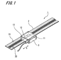
- FIG. 1 is a perspective view illustrating a displacement measuring apparatus according to a first embodiment of the present invention.
- the displacement measuring apparatus 1 is configured to carry out measurements of linear displacements, namely, as the so-called linear type displacement measuring apparatus.
- the displacement measuring apparatus 1 includes at least a composite scale 2 having a magnetic pattern 31 and a diffraction grating 32, each aligned in the direction X of measuring axis (or, hereinafter referred to as "measuring axis direction X"), and a detector head 3 moving in the measuring axis direction X relative to the composite scale 2.
- the detector head 3 includes at least a magnetic detection unit 11, a light source 12, and an optical detection unit 13.
- the magnetic detection unit 11 included in the detector head 3 is configured to detect the magnetic field generated by the magnetic pattern 31 of the composite scale 2, where first reproduced signals are generated.
- an MR (magneto-resistive) element is employed, for example, which is capable of detecting the magnetic field utilizing the magneto-resistive effect.
- the light source 12 in the detector head 3 is a point light source which is configured to irradiate the diffraction grating 32 of the composite scale 2 with light.
- an LED light emitting diode
- the optical detection unit 13 is configured to detect (or photo-receive) the light diffracted by the diffraction grating 32, where second reproduced signals are generated.
- a photodiode (PD) may be employed.
- FIGS. 2 and 3 are views illustrating the composite scale 2 in the displacement measuring apparatus 1, where FIG. 2 is a perspective view showing the configuration of the composite scale 2 and FIG. 3 is a longitudinal section of the composite scale 2.
- the composite scale 2 includes a base material 21 provided thereon with the magnetic pattern 31, a resin layer 22 superposed on the base material 21 and provided with the diffraction grating 32 on one of the surfaces of the resin layer 22 opposite to the base material 21, a reflective film 23 formed on the other surface of the resin layer 22, and a protective film 24 covering the resin layer 22 provided thereon with the reflective film 23.
- the base material 21 in the composite scale 2 includes magnetic material such as iron, cobalt, and the like, to have a structure of thin strip shape (tape-shaped) extending along the measuring axis direction X.
- the base material 21 includes the magnetic pattern 31.
- the magnetic pattern 31 is formed by implementing a magnetic recording of a sequence of alternately repeated N and S magnetic poles along the measuring axis direction X, having a pitch P1 of the repetition. By detecting the magnetic field generated by the magnetic pattern 31 by means of the magnetic detection unit 11 in the detector head 3, the amount of relative displacement between the composite scale 2 and the detector head 3 can be measured.
- the base material in the present invention is not limited to the above illustration.
- the base material of the invention may be formed alternatively employing nonmagnetic materials such as aluminum, glass, and the like, which is provided on the surface thereof with magnetic components by coating so as to form a magnetic pattern with an alternate sequence of the N and S poles.
- the resin layer 22 of the composite scale 2 is formed by disposing an ultraviolet (UV) curable-resin, as an example of photo-curable resins, on top of one of the surfaces of the base material 21.
- UV ultraviolet
- the material for forming the resin layer 22 is not limited to photo-curable resins such as the abovementioned ultraviolet curable-resin, but thermosetting resins such as an epoxy resin (EP) and the like, may alternatively be employed, for example.
- EP epoxy resin
- the diffraction grating 32 is formed on the other surface of the base material 21 opposing to the resin layer 22.
- the diffraction grating 32 has a plurality of slits formed thereon, which are aligned parallel with each other and perpendicular to the measuring axis direction X, where the slits are arranged in the direction X to be spaced with a pitch P2.
- the diffraction grating 32 is therefore formed on the same track as the magnetic pattern 31 on the base material 21.
- the diffraction grating 32 Upon irradiation with the light emitted from the light source 12 in the detector head 3, the diffraction grating 32 generates diffracted light.
- the optical detection unit 13 in the detector head 3 the amount of relative displacement between the composite scale 2 and the detector head 3 can be measured.
- the pitch P1 of the magnetic pattern 31 formed on the base material 21 is set herein to be larger than the pitch P2 of the diffraction grating 32 formed on the resin layer 22.
- the pitch P1 of the magnetic pattern 31 is set at 1000 ⁇ m so that the pitch of the first reproduced signals detected by the magnetic detection unit 11 is configured to be 1000 ⁇ m.
- the pitch P2 of the diffraction grating 32 is set at 4 ⁇ m.
- the pitch of the first reproduced signals generated from the detection by the magnetic method is larger than the second reproduced pitch generated from the optical detection.
- the reflective film 23 of the composite scale 2 is formed on the surface of the resin layer 22 by depositing a film of chromium (Cr), as a material with high hardness yet having suitable damage resistance, utilizing evaporation, sputtering, and other similar film deposition methods. While chromium is employed for forming the reflective film 23 hereinabove in the present embodiment, the material for the reflective film in the present invention is not limited to the above illustration.
- the reflective film of the invention may be formed alternatively employing other metals such as gold, platinum, aluminum, and the like.
- the protective film 24 is formed with a transparent material capable of passing through the light emitted from the light source 11.
- An example of the material for the protective film 24 includes polycarbonate (PC) that can be formed as a film.
- PC polycarbonate
- an adhesive agent may preferably be applied to one of the surfaces of the protective film 24.
- the reflective film 23 can be prevented from contamination or blemish by covering the resin layer 22 having the reflective film 23 thereon with the protective film 24.
- the diffracted light can be obtained in a prescribed manner to carry out precise displacement measurements, the reliability of the displacement measuring apparatus 1 can significantly be increased.
- the protective film of the invention is not limited to the abovementioned film of polycarbonate.
- the protective film of the invention not only include the films of polyethylene terephthalate (PET), but also include a film with other structure, such as a transparent resin material of polycarbonate (PC).
- the composite scale 2 according to the present embodiment includes the protective film 24 formed on the resin layer 22 having the reflective film 23 thereon; however, the composite scale 2 of the present embodiment may alternatively include no protective film 24.
- the reflective film 23 formed on the resin layer 22 serves as the surface of the composite scale 2.
- FIGS. 4A through 4F are cross-sectional views of the composite scale 2 at various fabrication steps.
- a magnetic pattern 31 of a pitch P1 is formed on a base material 21 by implementing magnetic recording of the sequence of alternately repeated S and N magnetic poles.
- a resin layer 22 is formed by disposing an ultraviolet curable-resin on one of the surfaces of the base material 21 which is previously provided with the magnetic pattern 31.
- the adhesion between the base material 21 and the resin layer 22 formed of ultraviolet curable-resin may be improved by additionally providing the process of roughening the surface of the base material 21.
- the ultraviolet curable-resin may alternatively be formed as a sheet having the size appropriate to the base material 21.
- the sheet-like ultraviolet curable-resin is attached onto the one of the surfaces of the base material 21.
- an original plate 35 which is provided thereon with a master (master grating) 35a corresponding to a diffraction grating 32, is pressed against the resin layer 22.
- the resin layer 22 is subjected to pressing process using the original plate 35.
- This original plate 35 is provided with a transparent material capable of passing through ultraviolet light, such as silica glass and the like, for example.
- the master 35a is subjected to a treatment for promoting its capability of suitably releasing the ultraviolet curable-resin.
- ultraviolet light beams are irradiated from the side of the original plate 35 by an ultraviolet light irradiation apparatus 42.
- the ultraviolet beams are thereby irradiated onto the resin layer 22 passing through the original plate 35, and the resin layer 22 is hardened while remaining pressed and deformed against the original plate 35.
- the original plate 35 is removed from thus hardened resin layer 22, where the diffraction grating 32 with a pitch P2 is formed on the resin layer 22. Since the releasing process has been made earlier on the master 35a of the original plate 35, the original plate 35 can be removed from the resin layer 22 with ease. As a result, an undesirable deformation of the hardened resin layer 22 can be prevented, and the diffraction grating 32 can be formed with a sufficient accuracy.
- chromium (Cr) is deposited to form a film on the surface of the resin layer 22 by evaporation, sputtering, and other suitable deposition methods, where a reflective film 23 is formed.
- a protective film 24 is formed on the resin layer 22 provided with the reflective film 23, where a composite scale 2 is fabricated.
- thermosetting resin a heating device is used for hardening the thermosetting resin instead of the ultraviolet light irradiation apparatus 42 shown in FIG. 4C . Since other process steps for forming the resin layer 22 employing thermosetting resin are similar to those mentioned earlier for forming the layer 22 with the ultraviolet curable-resin, the repeated description thereof is herewith abbreviated.
- the composite scale 2 included in the displacement measuring apparatus 1 can be formed through various steps in the fabrication process.
- An example thereof includes the steps of forming the magnetic pattern 31 on the base material 21, forming the resin layer 22 on the base material 21 provided thereon with the magnetic pattern 31, pressing the master 35a corresponding to the original plate 35 against the resin layer 22 and subsequently forming the diffraction grating 32, forming the reflective film 23 on the resin layer 22 provided thereon with the diffraction grating 32, and forming the protective film 24 on the resin layer 22 provided thereon with the reflective film 23.
- the diffraction grating 32 can be formed without using expensive manufacturing equipments and with relative ease, employing few manufacturing person-hours, where a significant cost-reduction can be achieved. Moreover, the diffraction grating 32 can be formed in a minute pitch with a sufficient accuracy, where more detailed and high resolution performances can be achieved during displacement measurements which are carried out by detecting the light which is diffracted by the thus formed diffraction grating 32, by means of the optical detection unit 13.
- the structure of thin tape shape has been illustrated hereinabove for the composite scale in the present embodiment, the structure is not limited to that of tape-shape for the composite scales of the invention.
- a further structure may alternatively be employed, where the base material is formed of metal such as stainless steel, and glass, etc., as mentioned earlier, to be a composite scale of lengthy shape having a suitable thickness.
- the displacement measuring apparatus 1 is configured to carry out measurements of the amount of displacement of the detector head 3 relative to the composite scale 2, either by detecting the magnetic field which is generated by the magnetic pattern 31 of the composite scale 2, by means of the magnetic detection unit 11 in the detector head 3, or by detecting the light which is diffracted by diffraction grating 32, by means of the optical detection unit 13.
- the magnetic pattern 31 of the compound scale 2 is formed with the pitch P1 larger than the pitch P2 of the diffraction grating 32, and the pitch of the first reproduced signals generated by the magnetic detection unit 11 is larger than the pitch P2 of the second reproduced signals generated by the optical detection unit 13. Therefore, by implementing the magnetic detection configured to detect the magnetic field generated from the magnetic pattern 31 by means of the magnetic detection unit 11 of the detector head 3, the displacement amount can be measured with high speed and response. Alternatively, by implementing the optical detection configured to detect the light diffracted with the diffraction grating 32 by means of the optical detection unit 13 of the detector head 3, the displacement amount can be measured in greater detail and with higher resolution.
- the measurements can be achieved not only in high speed and response, but also in greater detail as well as high resolution.
- FIG. 5 is a perspective view illustrating the displacement measuring apparatus according to a second embodiment of the invention.
- the displacement measuring apparatus 41 includes at least a composite scale 42 and a detector head 43 in a similar manner to the displacement measuring apparatus 1 according to the first embodiment.
- the displacement measuring apparatus 41 of the second embodiment is configured to measure the absolute position of the composite scale 42 relative to the detector head 43, that is, to be capable of performing the so-called absolute type measurements.
- the composite scale 42 in the displacement measuring apparatus 41 has a configuration similar to the composite scale 2 of the first embodiment except only for the structure of a magnetic pattern 51. Therefore, the magnetic pattern 51 is primarily described herein.
- the components in common with those in the composite scale 2 are indicated with identical numerical representations and the repeated description thereof is herewith abbreviated.
- the magnetic pattern 51 of the composite scale 42 represents a code 52 that can magnetically read position information (hereinafter referred to as "magnetic code”).
- the magnetic code 52 is described as follows. There formed on the base material 21 of the composite scale 42 are the portions each magnetically recorded corresponding to "1" information and other portions without magnetic recording each indicating "0" information.
- the information "1” may be formed by magnetically recording onto the base material 21 either with N or S magnetic pole, or alternatively with N and S poles in combination.
- the magnetic code 52 is expressed by numerical values of a plurality of digits, each having "0" or “1” information and being provided consecutively along the measuring axis direction X, so that the numerical values differ from each other. As shown in FIG. 5 , in the case where the magnetic code 52 is expressed by numerical values of four digits, the expression follows sequentially from one end, as "0010", “0100", “1001” and so on. By detecting this magnetic code 52, an arbitrary position on the composite scale 42 can be determined.
- the detector head 43 in the displacement measuring apparatus 41 has a configuration similar to the detector head 3 of the first embodiment except only for the structure of the magnetic detection unit 54. Therefore, the magnetic detection unit 54 is primarily described herein. The components in common with those included in the detector head 3 are indicated with identical numerical representations and the repeated description thereof is herewith abbreviated.
- the magnetic detection unit 54 includes four MR elements corresponding to the magnetic code 52 of four digits (four bits) and the interval between neighboring MR elements is set to be equal to the length corresponding to one digit on the magnetic codes 52.
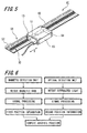
- FIG. 6 is a block diagram illustrating the absolute type measurement with the displacement measuring apparatus of FIG. 5 .
- the absolute type measurement with the displacement measuring apparatus 41 is carried out by the magnetic detection with the magnetic detection unit 54 in combination with the optical detection with the optical detection unit 13.
- the magnetic detection unit 54 first detects a magnetic code 52. Subsequently, signal processing is performed based on the value (voltage) detected by the magnetic detection unit 54, where first position information on the detection head 43 relative to the composite scale 42 is generated.
- the first position information is generated herein to the precision of 1.0 m ⁇ unit with the same order as the pitch of the second reproduced signal detected by the optical detection unit 13.
- the optical detection unit 13 first detects the light diffracted with the diffraction grating 32. Subsequently, signal processing is performed based on the value (voltage) detected by the optical detection unit 13, where second position information on the detection head 43 relative to the composite scale 42 is generated.
- the second position information is generated herein as the value smaller than the aforementioned pitch (1.0 m ⁇ ) of the second reproduced signals detected by the optical detection unit 13.
- the absolute position of the detection head 43 relative to the composite scale 42 is computed. Since the absolute position of the detection head 43 is thus measured by the magnetic detection and optical detection in combination, the detection of the absolute position can be carried out with high precision.
- the magnetic code 52 is expressed by numerical values of four digits (four bits) each having "0" or "1" in the present embodiment, the code 52 may alternatively be expressed by numerical values of five or more digits.
- the number of MR elements included in the magnetic detection unit is increased according to the number of the magnetic code. With the increase in the number of the magnetic code, the composite scale can be realized to be capable of measuring a longer distance by the absolute measurement method.
- the displacement measuring apparatus As described hereinabove, it is feasible with the displacement measuring apparatus according to the embodiments of the invention that by detecting the magnetic field generated from the magnetic pattern with the magnetic detector unit in the detector head, the displacement amount of the detector head relative to the composite scale can be measured with high speed and response. In addition, by detecting the light that is diffracted by the diffraction grating formed on the composite scale, with the optical detection unit of the detector head, the displacement amount can be measured in greater detail and with higher resolution.
- the desirable measurement method can be selected arbitrary between the abovementioned measurement methods, one being magnetic of realizing high speed and high response measurement and the other being optical for achieving more detailed and with higher resolution measurements, where the measurements will be feasible utilizing more suitable method depending on the status, and intention of the present use.
- the measurements can be achieved not only high speed and response, but also more detailed and with higher resolution.
- the composite scale according to the embodiment of the invention has the structure having the base material and the resin film formed on one of the surfaces of the resin material.
- the magnetic pattern is formed on the base material and the diffraction grating is formed on the resin film.
- the magnetic pattern and diffraction grating can be formed on the same track of the scale, where the reduction in size for the composite scale and for the measuring apparatus as a whole can be achieved.
- the diffraction grating is formed on the resin layer with photo-curable or thermosetting resin, diffraction gratings can be formed minutely defined with high precision only by the process of hardening while pressed against the original plate, with high precision and with relative ease. Moreover, the diffraction gratings are formed without having expensive manufacturing equipments and few manufacturing person-hours, where a significant cost-reduction can be achieved.
- the reflective film can be prevented from the occurrence of contamination or blemish.
- the diffracted light can be obtained continuously in a prescribed manner, and the durability and reliability of the measurement can be improved.
- the scale is formed to be tape-shaped by employing the thin strip shaped base material, the displacement measuring apparatus can be provided with the excellent transportability.
- the magnetic code from which position information can be read is provided as the magnetic pattern, absolute type measurements can be feasible. Moreover, since the absolute type measurements are carried out by merging the first position information obtained by detecting the magnetic code and the second position information obtained by detecting the light diffracted with the diffraction grating, the detection of the absolute position can be carried out with high precision.
- the displacement measuring apparatus has been shown as the linear type apparatus configured to make measurements of linear displacements, the measuring apparatus of the invention may be applied also to the rotary type capable of measuring rotational displacements.
Applications Claiming Priority (1)
| Application Number | Priority Date | Filing Date | Title |
|---|---|---|---|
| JP2007201283A JP2009036637A (ja) | 2007-08-01 | 2007-08-01 | 変位測定装置 |
Publications (2)
| Publication Number | Publication Date |
|---|---|
| EP2020591A2 true EP2020591A2 (fr) | 2009-02-04 |
| EP2020591A3 EP2020591A3 (fr) | 2013-10-09 |
Family
ID=39739591
Family Applications (1)
| Application Number | Title | Priority Date | Filing Date |
|---|---|---|---|
| EP08012121.3A Withdrawn EP2020591A3 (fr) | 2007-08-01 | 2008-07-04 | Appareil de mesure de déplacement |
Country Status (4)
| Country | Link |
|---|---|
| US (1) | US7808650B2 (fr) |
| EP (1) | EP2020591A3 (fr) |
| JP (1) | JP2009036637A (fr) |
| KR (1) | KR20090013681A (fr) |
Cited By (4)
| Publication number | Priority date | Publication date | Assignee | Title |
|---|---|---|---|---|
| EP2113742B1 (fr) * | 2008-04-30 | 2015-11-18 | Baumer Electric AG | Dispositif de mesure doté d'un balayage à deux canaux |
| EP2955487A1 (fr) * | 2014-06-09 | 2015-12-16 | DMG Mori Seiki Co. Ltd. | Dispositif de detection de position |
| CN106066182A (zh) * | 2015-04-24 | 2016-11-02 | 株式会社三丰 | 编码器标尺及其制造与附接方法 |
| WO2018001416A1 (fr) | 2016-07-01 | 2018-01-04 | Physik Instrumente (Pi) Gmbh & Co. Kg | Dispositif de détection |
Families Citing this family (15)
| Publication number | Priority date | Publication date | Assignee | Title |
|---|---|---|---|---|
| JP5594945B2 (ja) * | 2008-08-06 | 2014-09-24 | 日本トムソン株式会社 | アンプ回路を備えたスライド装置 |
| DE202009003253U1 (de) * | 2009-02-27 | 2010-07-22 | Balluff Gmbh | Kodierter Maßkörper und Positions-/Wegmesssystem |
| JP2011095180A (ja) * | 2009-10-30 | 2011-05-12 | Iai:Kk | エンコーダ及びサーボモータ |
| JP5567960B2 (ja) * | 2010-09-24 | 2014-08-06 | Dmg森精機株式会社 | 光学スケールの製造方法 |
| JP5695478B2 (ja) * | 2011-04-15 | 2015-04-08 | Dmg森精機株式会社 | 光学式変位測定装置 |
| US9035647B2 (en) * | 2012-07-02 | 2015-05-19 | Leine & Linde Ab | Encoder |
| JP5945632B2 (ja) * | 2012-08-23 | 2016-07-05 | エーエスエムエル ネザーランズ ビー.ブイ. | リソグラフィ装置、デバイス製造方法及び変位測定システム |
| JP5939956B2 (ja) * | 2012-10-12 | 2016-06-29 | Dmg森精機株式会社 | 変位検出装置 |
| CN103322919B (zh) * | 2013-05-27 | 2016-06-01 | 广东万濠精密仪器股份有限公司 | 光栅尺及其快速找零位的方法 |
| US9733317B2 (en) | 2014-03-10 | 2017-08-15 | Dmg Mori Seiki Co., Ltd. | Position detecting device |
| US10113888B2 (en) * | 2015-03-03 | 2018-10-30 | Canon Kabushiki Kaisha | Position detection apparatus, apparatus including the same and position detection method |
| JP6494330B2 (ja) * | 2015-03-03 | 2019-04-03 | キヤノン株式会社 | 位置検出装置およびこれを用いた装置 |
| JP6555903B2 (ja) * | 2015-03-03 | 2019-08-07 | キヤノン株式会社 | 位置検出装置およびこれを用いた装置 |
| JP6694355B2 (ja) * | 2016-09-01 | 2020-05-13 | 浜松ホトニクス株式会社 | 可動回折格子及びその製造方法、並びに外部共振器型レーザモジュール |
| CN113029002B (zh) * | 2021-03-18 | 2021-12-07 | 中国科学院长春光学精密机械与物理研究所 | 一种直线位移测量装置及方法 |
Citations (3)
| Publication number | Priority date | Publication date | Assignee | Title |
|---|---|---|---|---|
| JP2002267493A (ja) | 2001-03-07 | 2002-09-18 | Matsushita Electric Ind Co Ltd | 磁気式エンコーダ |
| JP2006177876A (ja) | 2004-12-24 | 2006-07-06 | Mitsutoyo Corp | 変位検出装置 |
| JP2007201283A (ja) | 2006-01-27 | 2007-08-09 | Denso Corp | 電子制御装置及び電子制御装置の筐体 |
Family Cites Families (14)
| Publication number | Priority date | Publication date | Assignee | Title |
|---|---|---|---|---|
| EP0013799B1 (fr) * | 1978-12-19 | 1985-10-02 | Kabushiki Kaisha Toshiba | Equipement de codage pour dispositifs très précis de mesure de longueurs ou d'angles |
| JPS60129613A (ja) * | 1983-12-19 | 1985-07-10 | Omron Tateisi Electronics Co | 回転検出装置 |
| JPS6176308U (fr) * | 1984-10-26 | 1986-05-22 | ||
| US5066130A (en) * | 1988-05-10 | 1991-11-19 | Canon Kabushiki Kaisha | Displacement measuring apparatus |
| WO1989011080A1 (fr) * | 1988-05-10 | 1989-11-16 | Siemens Aktiengesellschaft | Capteur angulaire a position codee |
| US4991125A (en) * | 1989-04-19 | 1991-02-05 | Mitutoyo Corporation | Displacement detector |
| JPH04211202A (ja) * | 1990-03-19 | 1992-08-03 | Canon Inc | 反射型回折格子および該回折格子を用いた装置 |
| US6449035B1 (en) * | 1999-05-12 | 2002-09-10 | John Samuel Batchelder | Method and apparatus for surface particle detection |
| JP2002090114A (ja) * | 2000-07-10 | 2002-03-27 | Mitsutoyo Corp | 光スポット位置センサ及び変位測定装置 |
| JP4020713B2 (ja) * | 2002-06-27 | 2007-12-12 | オリンパス株式会社 | 光学式エンコーダ |
| GB0415141D0 (en) * | 2004-07-06 | 2004-08-11 | Renishaw Plc | Scale reading apparatus |
| US7777879B2 (en) * | 2007-02-01 | 2010-08-17 | Stmicroelectronics (Research & Development) Ltd. | Rotary encoders |
| CN104111588B (zh) * | 2007-07-18 | 2016-08-03 | 株式会社尼康 | 测量方法、载台装置、及曝光装置 |
| NL1036080A1 (nl) * | 2007-11-01 | 2009-05-07 | Asml Netherlands Bv | Position measurement system and Lithographic Apparatus. |
-
2007
- 2007-08-01 JP JP2007201283A patent/JP2009036637A/ja active Pending
-
2008
- 2008-07-04 KR KR1020080064847A patent/KR20090013681A/ko not_active Application Discontinuation
- 2008-07-04 EP EP08012121.3A patent/EP2020591A3/fr not_active Withdrawn
- 2008-07-23 US US12/177,977 patent/US7808650B2/en active Active
Patent Citations (3)
| Publication number | Priority date | Publication date | Assignee | Title |
|---|---|---|---|---|
| JP2002267493A (ja) | 2001-03-07 | 2002-09-18 | Matsushita Electric Ind Co Ltd | 磁気式エンコーダ |
| JP2006177876A (ja) | 2004-12-24 | 2006-07-06 | Mitsutoyo Corp | 変位検出装置 |
| JP2007201283A (ja) | 2006-01-27 | 2007-08-09 | Denso Corp | 電子制御装置及び電子制御装置の筐体 |
Cited By (7)
| Publication number | Priority date | Publication date | Assignee | Title |
|---|---|---|---|---|
| EP2113742B1 (fr) * | 2008-04-30 | 2015-11-18 | Baumer Electric AG | Dispositif de mesure doté d'un balayage à deux canaux |
| EP2955487A1 (fr) * | 2014-06-09 | 2015-12-16 | DMG Mori Seiki Co. Ltd. | Dispositif de detection de position |
| US9719805B2 (en) | 2014-06-09 | 2017-08-01 | Dmg Mori Seiki Co., Ltd. | Position detecting device |
| CN106066182A (zh) * | 2015-04-24 | 2016-11-02 | 株式会社三丰 | 编码器标尺及其制造与附接方法 |
| CN106066182B (zh) * | 2015-04-24 | 2020-05-22 | 株式会社三丰 | 编码器标尺及其制造与附接方法 |
| WO2018001416A1 (fr) | 2016-07-01 | 2018-01-04 | Physik Instrumente (Pi) Gmbh & Co. Kg | Dispositif de détection |
| US10627263B2 (en) | 2016-07-01 | 2020-04-21 | Physik Instrumente (Pi) Gmbh & Co. Kg | Sensor device |
Also Published As
| Publication number | Publication date |
|---|---|
| US7808650B2 (en) | 2010-10-05 |
| US20090033946A1 (en) | 2009-02-05 |
| JP2009036637A (ja) | 2009-02-19 |
| EP2020591A3 (fr) | 2013-10-09 |
| KR20090013681A (ko) | 2009-02-05 |
Similar Documents
| Publication | Publication Date | Title |
|---|---|---|
| US7808650B2 (en) | Displacement measuring apparatus | |
| EP1669724B1 (fr) | Codeur photoélectrique et grille correspondante, et leur procédé de fabrication | |
| JP5172195B2 (ja) | 光学式変位測定装置 | |
| US7612331B2 (en) | Code disk with a plurality of tracks having different patterns | |
| EP0220757B1 (fr) | Elément transducteur optique et dispositif de mesure de déplacements comportant un tel élément | |
| EP2946176B1 (fr) | Échelle de mesure avec une nanostructure périodique | |
| JP2007173614A (ja) | 微細加工装置 | |
| US5760392A (en) | Scale for use with a displacement sensor | |
| US7343693B2 (en) | Scale assembly for optical encoder having affixed optical reference markers | |
| BE1007404A3 (nl) | Encoder element. | |
| EP0395374A1 (fr) | Echelle métrologique optique | |
| EP2208013B1 (fr) | Echelle métrologique et procédé de fabrication | |
| JP5789409B2 (ja) | 光学スケール | |
| ITTO20001067A1 (it) | Trasduttore di lettura/scrittura per dispositivi a disco rigido a doppio stadio di attuazione e relativo processo di fabbricazione. | |
| EP2946175B1 (fr) | Procédé de lecture de données représentées par une nanostructure périodique et polarisante | |
| JP2002202152A (ja) | 磁気式エンコーダー | |
| EP0644532A1 (fr) | Unité, bras, méthode et dispositif pour déterminer la position des bras de lecture-écriture des disques d'ordinateurs pendant l'enregistrement dans des pistes servo | |
| US20050259274A1 (en) | Method and apparatus for measuring displacement | |
| HUT50966A (en) | Method for determining position and construction for carrying out thereof |
Legal Events
| Date | Code | Title | Description |
|---|---|---|---|
| PUAI | Public reference made under article 153(3) epc to a published international application that has entered the european phase |
Free format text: ORIGINAL CODE: 0009012 |
|
| AK | Designated contracting states |
Kind code of ref document: A2 Designated state(s): AT BE BG CH CY CZ DE DK EE ES FI FR GB GR HR HU IE IS IT LI LT LU LV MC MT NL NO PL PT RO SE SI SK TR |
|
| AX | Request for extension of the european patent |
Extension state: AL BA MK RS |
|
| RAP1 | Party data changed (applicant data changed or rights of an application transferred) |
Owner name: MAGNESCALE CO., LTD. |
|
| PUAL | Search report despatched |
Free format text: ORIGINAL CODE: 0009013 |
|
| AK | Designated contracting states |
Kind code of ref document: A3 Designated state(s): AT BE BG CH CY CZ DE DK EE ES FI FR GB GR HR HU IE IS IT LI LT LU LV MC MT NL NO PL PT RO SE SI SK TR |
|
| AX | Request for extension of the european patent |
Extension state: AL BA MK RS |
|
| RIC1 | Information provided on ipc code assigned before grant |
Ipc: G01D 5/58 20060101ALI20130904BHEP Ipc: G01D 5/56 20060101AFI20130904BHEP |
|
| AKY | No designation fees paid | ||
| RAP1 | Party data changed (applicant data changed or rights of an application transferred) |
Owner name: MORI SEIKI CO., LTD. |
|
| REG | Reference to a national code |
Ref country code: DE Ref legal event code: R108 Effective date: 20140618 |
|
| STAA | Information on the status of an ep patent application or granted ep patent |
Free format text: STATUS: THE APPLICATION IS DEEMED TO BE WITHDRAWN |
|
| 18D | Application deemed to be withdrawn |
Effective date: 20140410 |