EP2017579B1 - Fahrzeugnavigationssystem - Google Patents
Fahrzeugnavigationssystem Download PDFInfo
- Publication number
- EP2017579B1 EP2017579B1 EP08011457.2A EP08011457A EP2017579B1 EP 2017579 B1 EP2017579 B1 EP 2017579B1 EP 08011457 A EP08011457 A EP 08011457A EP 2017579 B1 EP2017579 B1 EP 2017579B1
- Authority
- EP
- European Patent Office
- Prior art keywords
- road
- cross
- travel
- display
- display position
- Prior art date
- Legal status (The legal status is an assumption and is not a legal conclusion. Google has not performed a legal analysis and makes no representation as to the accuracy of the status listed.)
- Ceased
Links
- 230000002093 peripheral effect Effects 0.000 claims description 8
- 238000004904 shortening Methods 0.000 claims description 3
- 238000000034 method Methods 0.000 description 21
- 238000013500 data storage Methods 0.000 description 11
- 238000010586 diagram Methods 0.000 description 9
- 238000001514 detection method Methods 0.000 description 7
- 238000012545 processing Methods 0.000 description 6
- 238000013459 approach Methods 0.000 description 2
- 238000005452 bending Methods 0.000 description 2
- 238000004891 communication Methods 0.000 description 2
- 238000013519 translation Methods 0.000 description 2
- 241000743339 Agrostis Species 0.000 description 1
- 238000004364 calculation method Methods 0.000 description 1
- 230000000295 complement effect Effects 0.000 description 1
- 230000001419 dependent effect Effects 0.000 description 1
- 238000000605 extraction Methods 0.000 description 1
- 239000004973 liquid crystal related substance Substances 0.000 description 1
- 230000005236 sound signal Effects 0.000 description 1
Images


Classifications
-
- G—PHYSICS
- G01—MEASURING; TESTING
- G01C—MEASURING DISTANCES, LEVELS OR BEARINGS; SURVEYING; NAVIGATION; GYROSCOPIC INSTRUMENTS; PHOTOGRAMMETRY OR VIDEOGRAMMETRY
- G01C21/00—Navigation; Navigational instruments not provided for in groups G01C1/00 - G01C19/00
- G01C21/26—Navigation; Navigational instruments not provided for in groups G01C1/00 - G01C19/00 specially adapted for navigation in a road network
- G01C21/34—Route searching; Route guidance
- G01C21/36—Input/output arrangements for on-board computers
- G01C21/3667—Display of a road map
- G01C21/3673—Labelling using text of road map data items, e.g. road names, POI names
Definitions
- the present invention relates to a navigation system for a vehicle.
- a conventional in-vehicle navigation system displays, on a road map, characters such as: address names or administrative district names including names of prefectures, cities, and towns; facility names including park names; and road names. Users can thus acquire information on names to specify an area where the vehicle runs, peripheral facilities, and relevant roads.
- display positions of such information on names are predetermined in road map data; thus, each name is displayed at a corresponding predetermined position on a road map.
- the address names or facility names are generally necessary for a user to confirm a place the vehicle runs.
- a user determines an approximate route to a desired destination, and thereby drives a vehicle.
- the names of relevant roads are therefore more important than those of addresses or facilities for such a user. This is because the user determines one by one which road to run along the approximate route based on road names in many cases.
- the necessity that the user understands all the road names displayed in the navigation system is low. That is, the user can drive the vehicle along the previously determined route as long as the user can know the road subsequent to the present road the vehicle is running.
- Document US 2005/0052413 A1 describes a display apparatus constructed of a display device for displaying a character and a map display processing part that receives a setting from which side the display device is viewed, and rotates a character to be displayed on the screen of the display device if the inclination of the character with respect to a horizontal line is out of a predetermined range of angle that is decided according to said set side.
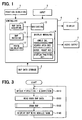
- FIG. 1 is a block diagram illustrating an overall configuration of the navigation system for a subject vehicle.
- the navigation system mounted in the subject vehicle includes the following: a position detection device 1, a map data storage device 2, an input device 3, and a controller 4 as a control apparatus connected to the foregoing.
- the system further includes a display device 6 and an audio output device 7, both of which are connected to the controller 4.
- the position detection device 1 functions as a detecting means to include known sensors such as a geomagnetic sensor, a gyro sensor, a speed sensor, and a GPS sensor to detect a present position of the vehicle based on radio waves from satellites.
- the individual sensors have different types of detection errors from each other; therefore, they are used to complement each other.
- the position detection device 1 may be constructed of a part of the above sensors depending on the accuracy of each sensor.
- the map data storage device 2 is used to input to the controller 4 road map data such as road data and background data for drawing road maps.
- the map data storage device 2 is provided with a storage medium storing the road map data such as a DVD-ROM, a hard disk drive (HDD) which are used from a required data volume.
- the map data storage device 2 functions as a map data storing means.
- Another storage medium may be used alternatively.
- the map data storage device 2 may be constructed of a communication device to acquire the map data from an external server etc.
- the input device 3 (referred to as a switch information input device) is used for various inputs and includes a mechanical switch arranged, for example in a periphery of the display device 6 or a touch switch integrated into a display screen in the display device 6.
- the navigation system according to the present embodiment has a known navigation function or a route guidance function.
- a destination is inputted via the input device 3, an optimal route to the destination from the present position is automatically selected as a guide route.
- a route guidance or navigation along the guide route is performed using the audio output device 7 and the display device 6.
- the display device 6 functions as a displaying means to include a liquid crystal display, for example, and have a display screen.
- the display device 6 displays, on the display screen, a peripheral road map around a present position of the vehicle along with a vehicle mark indicating the present position and heading direction of the vehicle based on the present position detected by the position detection device 1 and the road map data inputted from the map data storage device 2.
- the display device 6 further displays a selection display window for selecting a destination and a setting display window for setting ON/OFF of various kinds of functions of the navigation system.
- the audio output device 7 includes a speaker to output sounds for route guidance and explanation to operate the navigation system.
- the display device 6 and the audio output device 7 can function as a notification means for notifying a user of various information.
- the controller 4 is a usual computer to contain a CPU, a ROM, a RAM, an I/O circuit, and a bus line connected with the foregoing.
- a program for the controller 4 is written in the ROM. Based on the program, the CPU or the like executes predetermined data processing.
- main functions executed by the controller 4 are illustrated as a functional block diagram. That is, the controller 4 includes a map data acquiring portion 10, a map matching portion 11, a route calculating portion 12, a navigating portion (or a route guiding portion) 13, and a display managing portion (or display controlling portion) 14.
- portion can be referred to as a device, a control device, or control unit.
- the map data acquiring portion 10 acquires from the map data storage device 2 peripheral road map data of a periphery including the present position detected by the position detection device 1, and gives it to the display managing portion 14.
- the display managing portion 14 draws a road map to a VRAM (Video Random Access Memory) based on the road map data provided from the map data storage device 2, and provides to the display device 6 a display signal for displaying the peripheral road map around the present position and the vehicle mark.
- VRAM Video Random Access Memory
- a swept path of the vehicle is accumulated in the map matching portion 11 as the vehicle travels.
- the map matching portion 11 collates the swept path of the vehicle with configurations (such as straight, curved) of roads.
- the map matching portion 11 gives a correct position of the subject vehicle to the display managing portion 14.
- the display managing portion 14 thus corrects the position of the subject vehicle on the road map displayed in the display device 6.
- the route calculating portion 12 when a destination is inputted via the input device 3, the route calculating portion 12 generates an optimal guide route from the present position to the destination.
- the road map data from the present position to the destination is acquired from the map data storage device 2; and the route calculating portion 12 applies the technique such as the well-known Dijkstra method to the acquired road map data and generates an optimal guide route.
- the generated guide route is given to the navigating portion (or route guiding portion) 13.
- the navigating portion 13 instructs the display managing portion 14 to discernibly display a road corresponding to the generated guide route using a specific color in the road map displayed in the display device 6.
- the navigating portion 13 calculates guidance points such as an intersection which the vehicle should turn right/left, and outputs to the audio output device 7 an audio signal to notify by sounds the direction of the right/left turn in the guidance point.
- the navigating portion 13 gives the information about the guidance point to the display managing portion 14.
- the display managing portion 14 generates a display signal for displaying an enlarged view near the intersection and a sketch of the highway in the display device 6.
- the following explains a display process of a road map and a display managing or controlling process of a road name displayed on the road map.
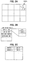
- all display range of road map data are divided in mesh into rectangular map segments called parcels, which are individually stored in the map data storage device 2.
- the parcel or each map segment of the road map data includes background data and road data.
- the background data are data on background of displayed road maps, such as a natural feature and a railway line.
- the road data are data for display roads based on actual roads.
- the road data has link string data indicating the configuration, the width, the number of lanes, and the like of each road included in one parcel.
- a road is represented by links; a link connects nodes therebetween; a node includes an intersecting point, a branching point, a linking point, or the like.
- a configuration interpolation point is designated between nodes to simulate an actual road having the configuration not straight.
- a line segment is defined or drawn between a node and a configuration interpolation point or between configuration interpolation points.
- a link includes multiple line segments.
- the link string data have data about multiple links which are included in a single parcel and which indicate road portions with an identical name or an identical travel condition.
- a single parcel includes a road A and a road B.
- the road data of the parcel has link string data A corresponding to the road A and link string data B corresponding to the road B.
- the link string data A includes configuration information to indicate a configuration of each link, link ID information to indicate a link ID uniquely assigned to each link for identification, a road name address to indicate a storage area storing the road name of the road A corresponding to link string data A, width/lane information to indicate a width and the number of lanes of the road A, and the like.
- the configuration information of each link includes coordinate string of the coordinates of the both ends and the configuration interpolation point(s).
- the road name address to indicate the storage area storing the corresponding road name is included in the link string data; thus, the road name can be read out using the road name address.
- the road names are stored in order in the storage areas corresponding to the road name addresses of each link string data, as illustrated in FIG. 2C .
- a present position and heading direction of the vehicle are detected based on a detecting result by the position detection device 1.
- the road map data for drawing a peripheral road map of a periphery of the present position of the vehicle detected at S110 is read from the map data storage device 2 with respect to each parcel based on the present position.
- the road map is drawn to the VRAM in the display managing portion 14 based on the read road map data. The drawing process of the road map is explained in detail later.
- the VRAM in the display managing portion 14 is capable of drawing the road map larger than the range of the display screen in the display device 6 in order to perform a scroll display of the road map with the travel of the vehicle.
- the display managing portion 14 designates a display range such that a subject vehicle mark is displayed in a constant point and the heading direction is upward, and generates a display signal to display the road map having the designated display range in the display device 6.
- the display managing portion 14 may display the road map such that a predetermined orientation (for example, north) is upward in the display screen.
- the VRAM of the display managing portion 14 includes drawing areas for individually drawing the background, the road, and the name.
- the display managing portion 14 generates a display signal, which piles up or overlaps the data drawn individually in the drawing areas, and gives it to the display device 6.
- the background of the road map is drawn to the drawing area for drawing the background based on the background data of the read road map data.
- each road is drawn to the drawing area for drawing the road based on the configuration information of the read road map data.
- the display managing portion 14 reads out the road name which should be displayed based on the road name address in the link string data of the road data and determines a display position of each road name based on a process to be mentioned later. Each name is drawn in the determined display position.
- the drawn road map is maintained until the vehicle moves to approach the end of the drawing area.
- a road map is newly drawn in the VRAM to follow the end of the drawing area while removing the unnecessary road map from the VRAM.
- a condition is fulfilled when the heading direction of the vehicle changes with the travel and the angle of the road map displayed changes a predetermined degree or more (for example, 45 degrees or more).
- another condition is fulfilled when the road the vehicle runs is changed, when the guide route changes, or when the node of an intersection is passed through.
- a road estimated to travel or referred to as a travel-estimated road is defined as a road which the subject vehicle is estimated to travel or run from now on. Further, if the route guidance or navigating is presently being performed, the road along which the navigating is performed is regarded as the travel-estimated road; if the route guidance is not being performed, the road the subject vehicle presently travels is regarded as the travel-estimated road.
- a cross road is extracted which intersects with the travel-estimated road. For instance, link string data are extracted which include the link having the node of the same coordinates included in the links constituting the travel-estimated road.
- a road, which intersects with the travel-estimated road with an overpass or underpass is excluded from candidates for the above extraction.
- the road name of the cross road is read based on the road name address of the link string data of the extracted cross road.
- a display position of the cross road is determined such that the road name is displayed in proximity to the cross road and the travel-estimated road without overlapping with the travel-estimated road.
- a road extends in both left and right sides relative to the travel-estimated road while the both sides have the same road name.
- the display position is defined such that the priority for displaying is given to the right side of the cross road.
- the display position is defined such that the priority for displaying is given to the left side of the cross road.
- a road extends in both left and right sides relative to the travel-estimated road while each intersecting point is deviated from each other.
- the display position is determined such that the road side corresponding to the intersecting point closer to the subject vehicle is prioritized in displaying.
- the display position is further determined in a specific condition with the following procedure.
- an intersecting angle centering on an intersection between a cross road and a travel-estimated road is obtained between (i) an initial link exiting directly from the intersection of the left or right side selected as the display target of the cross road and (ii) a link directly entering the intersection and closer to the subject vehicle than the intersection.
- the intersecting angle can be obtained with calculation based on the coordinate information of each link.
- the line segment up to the configuration interpolation point is used for obtaining the intersecting angle.
- the line segment from the intersection up to the configuration interpolation point is used for obtaining the intersecting angle.
- the intersecting angle is obtained from, of both the cross road and travel-estimated road, straight portions directly connected with the intersection therebetween.
- An intersecting angle can be differently obtained or defined.
- an intersecting angle may be obtained between (i) the cross road and (ii) an initial link of the travel-estimated road directly exiting from the intersection and farther to the subject vehicle than the intersection.
- an intersecting angle can be obtained between (i) the cross road and (ii) a reference line orthogonal to the travel-estimated road at the intersection.
- a search area is designated based on the obtained intersecting angle on the road map data.
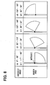
- a search area is used or defined as being shaped of a sector having a sector central angle of 45 degrees with a predetermined constant radius.
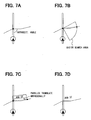
- a range of the search area is determined based on the obtained intersecting angle. For example, as shown in (a) in FIG. 8 , when an intersecting angle is 0 to 89 degrees, the sector centering on the intersecting point (i.e., intersection) between the cross road and the travel-estimated road is arranged such that a side of the sector contacts a road portion of the travel-estimated road entering the intersection and closer to the subject vehicle than the intersection.
- the sector search area pivots counter clockwise stepwise, every 30 degrees, for example.
- the sector search area is designated such that another side of the sector contacts a road portion of the travel-estimated road exiting from the intersection and farther to the subject vehicle than the intersection.
- the central angle of the sector search area may be an angle other than 45 degrees.
- the angle pivoted stepwise of the sector search area may be other than every 30 degrees.
- the sector search area should just be designated to include the direction in which the cross road is expected to extend from the travel-estimated road.
- intersecting angles (a') to (d') are defined as being between the cross road and a reference line orthogonal to the travel-estimated road at the intersection.
- the sector search area is thus designated.
- an arc intersecting point is obtained between the cross road and an outer circumference line (arc) of the sector search area.
- arc outer circumference line
- FIG. 7B a line segment is drawn to connect between (i) the intersection of the travel-estimated road and (ii) the arc intersecting point of the sector search area.
- the line segment is moved or parallel translated orthogonally to the line segment itself by a predetermined number of dots in the display screen of the display device 6, thus obtaining a parallel line segment.
- the display position of the road name of the cross road is determined such that the lower end of the road name accords with the moved line segment or the parallel line segment obtained by the parallel translation, as illustrated in FIG. 7C . Then, as illustrated in FIG. 7D , the road name is displayed on the determined position. As a result, the display of the road name of the cross road is in proximity to the travel-estimated road while having the same inclination as the line segment.
- the display of the road name can be on the basis of the line segment (namely, cross road). Therefore, the display of the road name in proximity to the travel-estimated road is located such that a user can clearly recognize that such a road name indicates the cross road. As a result, the user can determine which road the subject vehicle should proceed to, easily and correctly by using the displayed road name as a signpost.
- a sector search area with the above predetermined radius may not find an arc intersecting point with the cross road.
- a sector search area is re-designated with a radius shorter than the previous predetermined radius so as to find an arc intersecting point with the cross road.
- the sector search area is re-designated with a much shorter radius.
- the road name is displayed in the upper side of the cross road in the display screen.
- Such a display position or arrangement of a road name relative to the cross road is adopted to generally enable a user to recognize easier.
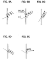
- FIG. 9A illustrates an example where an intersecting angle is so large as to overlap the road name and the travel-estimated road therebetween if the road name is displayed in the upper side of the cross road. That is, the line segment obtained using the above-mentioned procedure is parallel translated in a direction orthogonal to the extending direction of the line segment itself; the display position of the road name is determined that the lower end of the road name is located on the line segment parallel translated. In such a case, the display of the road name of the cross road and travel-estimated road partially overlap with each other. If such a display is practically performed, it is difficult to view the travel-estimated road.
- the display position of the road name is shifted along the inclination of the line segment to the position where the road name does not overlap with the travel-estimated road to find the renewed display position of the road name of the cross road, as illustrated in FIG. 9B .
- the above overlap between the travel-estimated road and the road name of the cross road may occur when the intersecting angle is equal to or greater than 90 degrees. Therefore, when an intersecting angle is equal to or greater than 90 degrees, a temporary display position is determined based on the position resulting from the parallel translation of the line segment upward in the display screen. With respect to the temporary display position, it is determined whether the overlap between the road name of the cross road and the travel-estimated road arises. If the overlap does not arise, the temporary display position is determined as a proper display position. In contrast, when the overlap arises, as mentioned above, the temporary display position is shifted parallel along the inclination of the line segment to a certain position where the above overlap disappears. The certain position is determined as a proper display position.
- FIG. 9C illustrates an example where the intersecting angle of the travel-estimated road and the cross road is larger than that in FIG. 9A , so that a display position of the road name of the cross road cannot be substantially secured.
- an intersecting angle exceeds 150 degrees, the area between the travel-estimated road and the upper side of the cross road is narrow, it is difficult to display the road name in the upper side of the cross road.
- the road name is displayed in the lower side of the cross road as illustrated in FIG. 9C .
- a line segment is obtained between (i) the travel-estimated road and the intersecting angle and (ii) an arc intersecting point between the outer circumference arc of the sector search area and the cross road; then, the line segment is parallel translated in the direction orthogonal to the line segment itself and shifted downward in the display screen by a predetermined display dots.
- the display position of the road name of the cross road is determined such that the upper end of the road name accords with the line segment parallel translated.
- the road name of the cross road can be displayed with a high possibility in proximity to the travel-estimated road so as not to overlap the cross road or travel-estimated road. The display of the road name can be thus performed for the user to view easily.
- FIG. 9D illustrates an example where an intersecting angle between the travel-estimated road and the cross road is smaller than 90 degrees, thereby securing a display area for the road name of the cross road in the upper side of the cross road.
- the road name is displayed in the upper side of the cross road, it does not overlap with the travel-estimated road.
- defining a temporary display position explained in FIGs. 9A, 9B is not necessary. That is, the line segment obtained using the above-mentioned procedure is parallel translated in a direction orthogonal to the extending direction of the line segment itself; a proper display position of the road name is directly determined such that the lower end of the road name is located on the line segment parallel translated in the display screen.
- FIG. 9E illustrates an example where the cross road bents in multiple points.
- a line segment is obtained between (i) the travel-estimated road and the intersecting angle and (ii) an arc intersecting point between the outer circumference arc of the sector search area and the cross road; then, the display position is determined based on the obtained line segment.
- the cross road and its road name may partially overlap with each other as illustrated in FIG. 9E .
- the line segment is drawn to represent the whole of the cross road bending at the multiple points. Therefore, the road name can be displayed on the position based on the line segment such that the user can recognize that the road name represents the cross road.
- the cross road is not always a road the user should travel. Priority is thus given to the user's readability of the road name of the cross road while accepting some difficulty in viewing.
- the road name display of a cross road extended from an intersection the vehicle has already passed through has a lower priority than that of a cross road extended from an intersection the vehicle is going to pass through from now on. Accordingly, when the road names of both the cross roads overlap, the road name of the cross road extended from the intersection the vehicle has already passed through is not displayed.
- a cross road extended from an intersection closest to the vehicle has a higher priority in displaying a road name among intersections the vehicle is going to pass through. Accordingly, when the road names of the cross roads overlap, the road name of the cross road extended from the intersection farther than the closest intersection is not displayed.
- the priority in displaying road names is given based on the rank of roads such as national road > prefectural road > municipal road, the number of lanes, or width of road.
- the cross road extended diagonally forward is higher in the road rank than the cross road extended orthogonal to the travel-estimated road. Therefore, the road name of the cross road extended orthogonally to the travel-estimated road is not displayed.
- each road name is determined so as to draw the road name in the drawing area for drawing names.
- the name of the cross road which intersects with a present-travel road which is a road the vehicle is presently traveling or running, is displayed at a position in proximity to the the present-travel road and allowing the user to clearly recognize that the displayed road name corresponds to the cross road. Accordingly, the user can see easily the road name of the road the vehicle may run next. As a result, the user can determine which road the subject vehicle should proceed to, easily and correctly by using the displayed road name as a signpost.
- the road name of the present-travel road may be displayed on the road map along the present-travel road or on the top right of the display screen.
- the display priority of the road name of a cross road may be maintained as the higher than those of the address name or the facility name.
- the display position of the road name of the cross road is first determined preferentially with the procedure and the rule which are mentioned above.
- the display positions of the address name and the facility name are determined subsequently not to overlap with the road name of the cross road.
- the display positions of the address name and the facility name are determined under comparatively loose restriction, they can be displayed on the suitable positions in general.
- a software unit e.g., subroutine
- a hardware unit e.g., circuit or integrated circuit
- the hardware unit can be constructed inside of a microcomputer.
- the software unit or any combinations of multiple software units can be included in a software program, which can be contained in a computer-readable storage media or can be downloaded and installed in a computer via a communications network.
- a navigation system for a vehicle is provide as follows.
- a displaying means is configured to have a display screen.
- a detecting means is configured to detect a present position and a heading direction of the vehicle.
- a storing means is configured to store road map data for displaying a road map including a road name of a road.
- a display managing means is configured to read road map data from the storing means based on the detected present position, and display a peripheral road map and a vehicle mark indicating the present position and the heading direction such that the heading direction is shown upwardly in the display screen.
- the display managing means includes: (i) an angle calculating means for calculating, relative to a travel-estimated road, which is estimated for the vehicle to travel, an intersecting angle of an extending direction of a cross road intersecting with the travel-estimated road at an intersection; (ii) a search area designating means for designating a search area shaped of a sector centering on the intersection to include the extending direction of the cross road; (iii) an intersecting point retrieving means for retrieving an arc intersecting point between the cross road and an outer circumference arc of the designated search area; and (iv) a display position determining means for determining a display position of a road name of the cross road based on a line segment between the intersection and the retrieved arc intersecting point.
- one road may be chosen from the roads connected to the road which the vehicle runs now or the vehicle is estimated to run from now on.
- the above mentioned navigation system determines the display position of the road name of the cross road intersecting with the travel-estimated road of the vehicle as being displayed intelligibly for the user.
- the line segment and the cross road accord with each other.
- the road name can be displayed on the basis of the line segment (namely, cross road). If a cross road bends at multiple points, the line segment can be drawn to represent the whole of the cross road bending at multiple points. Therefore, the road name can be displayed on the position based on the line segment such that the user can recognize that the road name represents the cross road. As a result, the user can determine which road the subject vehicle should proceed to, easily and correctly by using the displayed road name as a signpost.
- the search area designating means may designate the search area with a first predetermined radius; and when no arc intersecting point is retrieved with the first predetermined radius, the search area designating means may re-designate a search area with a radius shorter than the first predetermined radius. Further, the search area designating means may repeatedly designate a search area while gradually shortening a radius from the first predetermined radius until an arc intersecting point is successfully retrieved.
- an arc intersecting point between the outer circumference arc and the cross road can be obtained by shortening a radius of the sector.
- the display position determining means may define the line segment between the intersection and the arc intersecting point and then define an additional line segment by parallel translating the line segment orthogonally to an extending direction of the line segment by a predetermined distance; and the display position determining means may determine, as the display position of the road name of the cross road, a position based on the additional line segment to have no overlap with the travel-estimated road.
- the display position determining means may find an intersecting angle between the line segment and a road portion of the travel-estimated road closer to the vehicle than the intersection; and when the intersecting angle is less than 90 degrees, the display position determining means may determine, as the display position of the road name of the cross road, a position defined by parallel translating the line segment upward in the display screen.
- the display position determining means may find an intersecting angle between the line segment and a road portion of the travel-estimated road closer to the vehicle than the intersection; when the intersecting angle is in a range from 90 degrees to a predetermined angle greater than 90 degrees, the display position determining means may determine, as a temporary display position of the road name of the cross road, a position defined by parallel translating the line segment upward in the display screen; and when the travel-estimated road overlaps with the road name in the temporary display position, the display position determining means may determine the display position of the road name of the cross road by shifting the temporary display position along an inclination of the line segment to a position to have no overlap with the travel-estimated road.
- the display position determining means may find an intersecting angle between the line segment and a road portion of the travel-estimated road closer to the vehicle than the intersection; and when the intersecting angle is greater than a predetermined angle exceeding 90 degrees, the display position determining means may determine, as the display position of the road name of the cross road, a position defined by parallel translating the line segment downward in the display screen.
- a navigation system for a vehicle is provided as follows.
- a displaying means is configured to have a display screen.
- a detecting means is configured to detect a present position and a heading direction of the vehicle.
- a storing means is configured to store road map data for displaying a road map including a road name of a road.
- a display managing means is configured to read road map data from the storing means based on the detected present position, and display a peripheral road map and a vehicle mark indicating the present position and the heading direction such that the heading direction is shown upwardly in the display screen.
- the display managing means displays a road name of a cross road, which intersects at an intersection with a travel-estimated road defined as a road the vehicle is estimated to travel, at a position in proximity to the cross road to have no overlap with the travel-estimated road; and the display managing means includes a display position determining means for determining a display position of the road name of the cross road at either an upper or a lower side of the cross road based on an intersecting angle between the cross road and a road portion of the travel-estimated road closer to the vehicle than the intersection.
- the road name of the cross road intersecting the travel-estimated road can be displayed to allow a user to view it easily.
- a navigating means may be further configured to navigate the vehicle along a guide route which is designated when a destination is specified.
- the display managing means may regard as the travel-estimated road the guide route along which the vehicle is being navigated.
- the display managing means may regard, as the travel-estimated road, a road following a road the vehicle runs when the vehicle is not navigated.
- a road following a road the vehicle runs can be defined as a road connected in a direction of natural progress of the presently traveling road without changing or turning to a cross road even if the cross road is present ahead of the vehicle.
- the cross road may be extended from the intersection to a right side and left side relative to the travel-estimated road.
- a road name may be displayed with respect to the right side of the cross road.
- a road name may be displayed with respect to the left side of the cross road.
Landscapes
- Engineering & Computer Science (AREA)
- Radar, Positioning & Navigation (AREA)
- Remote Sensing (AREA)
- Automation & Control Theory (AREA)
- Physics & Mathematics (AREA)
- General Physics & Mathematics (AREA)
- Navigation (AREA)
- Traffic Control Systems (AREA)
- Instructional Devices (AREA)
Claims (12)
- Navigationssystem für ein Fahrzeug, wobei das System aufweist:eine Anzeigeeinrichtung (6), die einen Anzeigebildschirm aufweist;eine Erfassungseinrichtung (1), die ausgelegt ist, eine derzeitige Position und eine Richtung des Fahrzeugs zu erfassen;eine Speichereinrichtung (2) die ausgelegt ist, Straßenkartendaten zum Anzeigen einer Straßenkarte, die einen Straßennamen einer Straße enthält, zu speichern; undeine Anzeigeverwaltungseinrichtung, die ausgelegt ist,Straßenkartendaten auf der Grundlage der erfassten derzeitigen Position aus der Speichereinrichtung zu lesen,eine Umgebungsstraßenkarte und eine Fahrzeugmarkierung, die die derzeitige Position und die Richtung angibt, derart anzuzeigen, dass die Richtung in dem Anzeigebildschirm aufwärts gerichtet gezeigt ist, undeinen Straßennamen einer Kreuzungsstraße, die sich an einer Kreuzung mit einer geschätzten Fahrstraße kreuzt, die als eine Straße des Fahrzeugs definiert ist, von der geschätzt wird, dass das Fahrzeug darauf fährt, an einer Position in der Nähe der Kreuzungsstraße anzuzeigen, ohne die geschätzte Fahrstraße zu überdecken, wobeidie Anzeigeverwaltungseinrichtung eine Anzeigepositionsbestimmungseinrichtung enthält, die ausgelegt ist, eine Anzeigeposition des Straßennamens der Kreuzungsstraβe auf einer oberen oder einer unteren Seite der Kreuzungsstraße zu bestimmen;dadurch gekennzeichnet, dassdie Anzeigepositionsbestimmungseinrichtung ausgelegt ist,die Anzeigeposition des Straßennamens der Kreuzungsstraße auf einer oberen oder einer unteren Seite der Kreuzungsstraße auf der Grundlage nur eines Kreuzungswinkels zwischen der Kreuzungsstraße und einem Straßenteil der geschätzten Fahrstraße, der näher bei dem Fahrzeug als die Kreuzung liegt, zu bestimmen,eine untere Seite der Kreuzungsstraße als Anzeigeposition des Straßennamens der Kreuzungsstraße zu bestimmen, wenn der Kreuzungswinkel einen vorbestimmten maximalen Winkel überschreitet, undeine obere Seite der Kreuzungsstraße als Anzeigeposition des Straßennamens der Kreuzungsstraße zu bestimmen, wenn der Schnittwinkel den vorbestimmten maximalen Winkel nicht überschreitet.
- Navigationssystem nach Anspruch 1, wobei
die Anzeigeverwaltungseinrichtung enthält:eine Winkelberechnungseinrichtung, die ausgelegt ist, einen Schnittwinkel zwischen einer Erstreckungsrichtung der Kreuzungsstraße an der Kreuzung und der geschätzten Fahrstraße zu berechnen;eine Suchbereichsbestimmungseinrichtung, die ausgelegt ist, einen Suchbereich, der aus einem Sektor, der um die Kreuzung zentriert ist, ausgebildet ist, zu bestimmen, der die Erstreckungsrichtung der Kreuzungsstraße enthält; undeine Kreuzungspunktermittlungseinrichtung, die ausgelegt ist, einen Bogenkreuzungspunkt zwischen der Kreuzungsstraße und einem Außenumfangsbogen des bestimmten Suchbereiches zu ermitteln,wobeidie Anzeigepositionsbestimmungseinrichtung ein Liniensegment zwischen der Kreuzung und dem Bogenkreuzungspunkt definiert und einen Kreuzungswinkel zwischen der geschätzten Fahrstraße und der Kreuzungsstraße Betrachten einer Erstreckungsrichtung des Liniensegmentes als Erstreckungsrichtung der Kreuzungsstraße findet. - Navigationssystem nach Anspruch 2, wobei
die Suchbereichsbestimmungseinrichtung den Suchbereich mit einem ersten vorbestimmten Radius bestimmt; und
wenn kein Bogenkreuzungspunkt mit dem ersten vorbestimmten Radius ermittelt wird, die Suchbereichsbestimmungseinrichtung einen Suchbereich mit einem Radius, der kürzer als der erste vorbestimmte Radius ist, neu bestimmt. - Navigationssystem nach Anspruch 3, wobei
die Suchbereichsbestimmungseinrichtung einen Suchbereich wiederholt bestimmt, während sie graduell einen Radius von dem ersten vorgebestimmten Radius verringert, bis ein Bogenkreuzungspunkt erfolgreich ermittelt wird. - Navigationssystem nach einem der Ansprüche 2 bis 4, wobei
die Anzeigepositionsbestimmungseinrichtung das Liniensegment zwischen der Kreuzung und dem Bogenkreuzungspunkt definiert und dann ein zusätzliches Liniensegment durch paralleles Verschieben des Liniensegmentes um einen vorbestimmten Abstand orthogonal zu einer Erstreckungsrichtung des Liniensegmentes definiert; und
die Anzeigepositionsbestimmungseinrichtung als Anzeigeposition des Straßennamens der Kreuzungsstraße eine Position auf der Grundlage des zusätzlichen Liniensegmentes ohne Überlagerung auf die geschätzte Fahrstraße bestimmt. - Navigationssystem nach Anspruch 5, wobei
die Anzeigepositionsbestimmungseinrichtung den Kreuzungswinkel zwischen dem Liniensegment und einem Straßenteil der Straße, auf dem eine Fahrt vor der Kreuzung geschätzt wird, findet; und
wenn der Kreuzungswinkel kleiner als 90 Grad ist, die Anzeigepositionsbestimmungseinrichtung als Anzeigeposition des Straßennamens der Kreuzungsstraße eine Position bestimmt, die durch Bewegen des Liniensegmentes parallel aufwärts in dem Anzeigebildschirm definiert wird. - Navigationssystem nach Anspruch 5, wobei
die Anzeigepositionsbestimmungseinrichtung den Kreuzungswinkel zwischen dem Liniensegment und einem Straßenteil der geschätzten Fahrstraße, der näher bei dem Fahrzeug als die Kreuzung liegt, findet;
wenn der Kreuzungswinkel in einem Bereich von 90 Grad bis zu einem vorbestimmten Winkel von größer als 90 Grad liegt, die Anzeigepositionsbestimmungseinrichtung als zeitweilige Anzeigeposition des Straßennamens der Kreuzungsstraße eine Position bestimmt, die durch paralleles Verschieben des Liniensegmentes aufwärts in dem Anzeigebildschirm definiert wird; und
wenn der Straßenname an der zeitweiligen Anzeigeposition die geschätzte Fahrstraße überlagert, die Anzeigepositionsbestimmungseinrichtung die Anzeigeposition des Straßennamens der Kreuzungsstraße durch Verschieben der zeitweiligen Anzeigeposition entlang einer Neigung des Liniensegmentes zu einer Position ohne Überlagerung der geschätzten Fahrstraße bestimmt. - Navigationssystem nach Anspruch 5, wobei
die Anzeigepositionsbestimmungseinrichtung einen Kreuzungswinkel zwischen dem Liniensegment und einem Straßenteil der geschätzten Fahrstraße, der näher bei dem Fahrzeug als die Kreuzung liegt, findet; und
wenn der Kreuzungswinkel größer als ein vorbestimmter Winkel ist, der 90 Grad überschreitet, die Anzeigepositionsbestimmungseinrichtung als Anzeigeposition des Straßennamens der Kreuzungsstraße eine Position bestimmt, die durch paralleles Verschieben des Liniensegmentes abwärts in dem Anzeigebildschirm definiert wird. - Navigationssystem nach einem der Ansprüche 1 bis 8, das außerdem aufweist:eine Navigationseinrichtung (13) zum Navigieren des Fahrzeugs entlang einer Führungsroute, die bestimmt wird, wenn ein Ziel spezifiziert wird, wobeidie Anzeigeverwaltungseinrichtung die Führungsroute, entlang der das Fahrzeug navigiert wird, als geschätzte Fahrroute betrachtet.
- Navigationssystem nach Anspruch 9, wobei
die Anzeigeverwaltungseinrichtung eine Straße, die einer Straße, auf der das Fahrzeug fährt, folgt, als geschätzte Fahrstraße betrachtet, wenn das Fahrzeug nicht navigiert wird. - Navigationssystem nach einem der Ansprüche 1 bis 10, wobei
die Kreuzungsstraße sich von der Kreuzung zu einer rechten Seite und linken Seite in Bezug auf die geschätzte Fahrstraße erstreckt;
wenn das Fahrzeug auf einer rechten Seite der geschätzten Fahrstraße fährt, der Straßenname in Bezug auf die rechte Seite der Kreuzungsstraße angezeigt wird; und
wenn das Fahrzeug auf einer linken Seite der geschätzten Fahrstraße fährt, der Straßenname in Bezug auf die linke Seite der Kreuzungsstraße angezeigt wird. - Navigationssystem nach einem der Ansprüche 1 bis 11, wobei
der Straßenname durch eine Zeichenkette von mehreren Zeichen präsentiert wird; und
die Zeichenkette des Straßennamens der Kreuzungsstraße von der Anzeigepositionsbestimmungseinrichtung auf der unteren Seite der Kreuzungsstraße und parallel zu der Kreuzungsstraße, die sich von der Kreuzung aus erstreckt, angezeigt wird, wenn der Kreuzungswinkel den vorbestimmten maximalen Winkel überschreitet, wohingegen
die Zeichenkette des Straßennamens der Kreuzungsstraße von der Anzeigepositionsbestimmungseinrichtung auf der oberen Seite der Kreuzungsstraße und parallel zu der Kreuzungsstraße, die sich von der Kreuzung aus erstreckt, angezeigt wird, wenn der Kreuzungswinkel den vorbestimmten maximalen Winkel nicht überschreitet.
Applications Claiming Priority (1)
| Application Number | Priority Date | Filing Date | Title |
|---|---|---|---|
| JP2007186163A JP4367538B2 (ja) | 2007-07-17 | 2007-07-17 | 車両用ナビゲーション装置 |
Publications (3)
| Publication Number | Publication Date |
|---|---|
| EP2017579A2 EP2017579A2 (de) | 2009-01-21 |
| EP2017579A3 EP2017579A3 (de) | 2011-06-01 |
| EP2017579B1 true EP2017579B1 (de) | 2014-08-06 |
Family
ID=39811960
Family Applications (1)
| Application Number | Title | Priority Date | Filing Date |
|---|---|---|---|
| EP08011457.2A Ceased EP2017579B1 (de) | 2007-07-17 | 2008-06-24 | Fahrzeugnavigationssystem |
Country Status (3)
| Country | Link |
|---|---|
| US (1) | US8548732B2 (de) |
| EP (1) | EP2017579B1 (de) |
| JP (1) | JP4367538B2 (de) |
Families Citing this family (14)
| Publication number | Priority date | Publication date | Assignee | Title |
|---|---|---|---|---|
| EP2141681A4 (de) * | 2007-03-28 | 2011-07-27 | Navitime Japan Co Ltd | Kartenanzeigesystem, kartenanzeige und kartenanzeigeverfahren |
| JP5474581B2 (ja) * | 2010-01-15 | 2014-04-16 | アルパイン株式会社 | 地図表示装置および地図表示方法 |
| JP5615607B2 (ja) * | 2010-07-06 | 2014-10-29 | アルパイン株式会社 | 地図表示装置及び地図表示方法 |
| US8849867B1 (en) * | 2010-07-23 | 2014-09-30 | Google Inc. | Intersection clustering in a map editor |
| DE112011105528T5 (de) | 2011-08-15 | 2014-05-08 | Mitsubishi Electric Corp. | Zeichenkettenanordnungsvorrichtung |
| US9347785B2 (en) | 2011-08-24 | 2016-05-24 | Mitsubishi Electric Corporation | Navigation device for displaying name of guidance intersection |
| JP5606640B2 (ja) * | 2012-01-12 | 2014-10-15 | 三菱電機株式会社 | 地図表示装置および地図表示方法 |
| JP6028387B2 (ja) * | 2012-05-11 | 2016-11-16 | 株式会社デンソー | 地図表示装置、及び、当該地図表示装置を備えるナビゲーションシステム |
| US9171527B2 (en) * | 2012-11-20 | 2015-10-27 | Google Inc. | System and method for displaying geographic imagery |
| KR101768137B1 (ko) * | 2015-10-12 | 2017-08-30 | 현대자동차주식회사 | 자동차용 지도 정보 표시 장치 및 그 제어방법 |
| JP6637066B2 (ja) * | 2015-11-06 | 2020-01-29 | 本田技研工業株式会社 | 車両走行制御装置 |
| CN105890614B (zh) | 2016-03-31 | 2019-06-04 | 百度在线网络技术(北京)有限公司 | 道路名称显示方法及装置 |
| JP6657129B2 (ja) * | 2017-01-31 | 2020-03-04 | 株式会社トヨタマップマスター | 地図作成装置、地図作成方法及びそのプログラム、記録媒体 |
| CN111220149B (zh) * | 2020-03-02 | 2022-01-28 | 腾讯科技(深圳)有限公司 | 移动设备的导航方法、装置、设备及计算机存储介质 |
Family Cites Families (22)
| Publication number | Priority date | Publication date | Assignee | Title |
|---|---|---|---|---|
| US4914605A (en) * | 1984-10-22 | 1990-04-03 | Etak, Inc. | Apparatus and method for displaying a map |
| JPH04288584A (ja) * | 1991-03-18 | 1992-10-13 | Pioneer Electron Corp | 地図表示装置 |
| JPH05197334A (ja) | 1992-01-17 | 1993-08-06 | Daihatsu Motor Co Ltd | 地図表示方法 |
| JPH0634384A (ja) * | 1992-07-16 | 1994-02-08 | Zexel Corp | 車両用ナビゲーション装置 |
| JP3468824B2 (ja) * | 1994-03-29 | 2003-11-17 | 本田技研工業株式会社 | 車両誘導装置 |
| JP3555191B2 (ja) * | 1994-09-02 | 2004-08-18 | 株式会社デンソー | 副経路設定装置およびナビゲーション装置 |
| US6188956B1 (en) * | 1998-12-30 | 2001-02-13 | Garmin Corporation | Navigation device and method for selectively displaying thoroughfare names |
| US6565610B1 (en) * | 1999-02-11 | 2003-05-20 | Navigation Technologies Corporation | Method and system for text placement when forming maps |
| US6424933B1 (en) | 2000-03-17 | 2002-07-23 | Vicinity Corporation | System and method for non-uniform scaled mapping |
| EP1282855B1 (de) | 2000-03-17 | 2011-10-12 | Microsoft Corporation | System und verfahren zur abstraktion und visualisierung einer routenkarte |
| JP4676684B2 (ja) * | 2003-08-26 | 2011-04-27 | クラリオン株式会社 | 車載情報端末 |
| JP4597496B2 (ja) | 2003-09-04 | 2010-12-15 | 三菱電機株式会社 | 表示装置 |
| JP2005115174A (ja) | 2003-10-09 | 2005-04-28 | Navitime Japan Co Ltd | 地図表示装置、地図表示方法および地図表示プログラム |
| JP4246055B2 (ja) * | 2003-12-19 | 2009-04-02 | アルパイン株式会社 | 車載用ナビゲーション装置及び周辺施設検索表示方法 |
| JP4009958B2 (ja) * | 2003-12-24 | 2007-11-21 | アイシン・エィ・ダブリュ株式会社 | ナビゲーション装置 |
| JP2005249589A (ja) * | 2004-03-04 | 2005-09-15 | Xanavi Informatics Corp | ナビゲーション装置、要約地図配信装置、車両案内方法および地図表示装置 |
| JP2005300168A (ja) | 2004-04-06 | 2005-10-27 | Alpine Electronics Inc | ナビゲーション装置及び地図表示方法 |
| US7430473B2 (en) * | 2004-10-01 | 2008-09-30 | Bose Corporation | Vehicle navigation display |
| JP4661439B2 (ja) * | 2004-11-22 | 2011-03-30 | 株式会社デンソー | 車両用ナビゲーション装置及び道路地図配信システム |
| KR100688018B1 (ko) * | 2005-02-16 | 2007-02-27 | 엘지전자 주식회사 | 도로 명 데이터의 표시위치 결정방법 |
| JP4741328B2 (ja) * | 2005-09-08 | 2011-08-03 | クラリオン株式会社 | ナビゲーション装置 |
| JP4609410B2 (ja) | 2006-10-18 | 2011-01-12 | 株式会社デンソー | 車両用ナビゲーション装置 |
-
2007
- 2007-07-17 JP JP2007186163A patent/JP4367538B2/ja not_active Expired - Fee Related
-
2008
- 2008-06-24 EP EP08011457.2A patent/EP2017579B1/de not_active Ceased
- 2008-07-15 US US12/219,006 patent/US8548732B2/en not_active Expired - Fee Related
Also Published As
| Publication number | Publication date |
|---|---|
| EP2017579A2 (de) | 2009-01-21 |
| EP2017579A3 (de) | 2011-06-01 |
| US20090024319A1 (en) | 2009-01-22 |
| JP4367538B2 (ja) | 2009-11-18 |
| US8548732B2 (en) | 2013-10-01 |
| JP2009025048A (ja) | 2009-02-05 |
Similar Documents
| Publication | Publication Date | Title |
|---|---|---|
| EP2017579B1 (de) | Fahrzeugnavigationssystem | |
| US6567744B1 (en) | In-vehicle navigation apparatus | |
| JP5590950B2 (ja) | ナビゲーション装置および誘導経路探索方法 | |
| JP5111084B2 (ja) | ナビゲーション装置 | |
| JP4096180B2 (ja) | ナビゲーション装置並びに該装置用プログラム及び記録媒体 | |
| CN105934653B (zh) | 导航装置 | |
| US8428865B2 (en) | Navigation system and roadway search method | |
| JP4619023B2 (ja) | 車載ナビゲーション装置、ナビゲーションシステム | |
| JP5393785B2 (ja) | ルート周辺施設検索装置 | |
| JP2006113460A (ja) | ナビゲーション装置、地図データ配信装置、地図データ配信システム | |
| US8504297B2 (en) | Map display device and map display method | |
| US8868331B2 (en) | Navigation apparatus | |
| JP4740651B2 (ja) | ナビゲーション装置 | |
| JP3190739B2 (ja) | 車両位置検出装置 | |
| JP2012149957A (ja) | 車載地図表示装置 | |
| JP4210869B2 (ja) | ナビゲーション装置並びに該装置用プログラム及び記録媒体 | |
| JP4835494B2 (ja) | 地図表示装置 | |
| JP4063176B2 (ja) | 地図表示装置 | |
| JP2004317327A (ja) | ナビゲーション装置並びに該装置用プログラム及び記録媒体 | |
| JP2009020181A (ja) | 地図表示装置 | |
| EP1134553A2 (de) | Bord-Fahrzeugnavigationsvorrichtung | |
| JP2916459B2 (ja) | 車両用ナビゲーション装置 | |
| JP2008180574A (ja) | ナビゲーション装置 | |
| JP2011242245A (ja) | ナビゲーション装置 | |
| JP2009025166A (ja) | 車載用ナビゲーション装置及び微小角分岐判定方法 |
Legal Events
| Date | Code | Title | Description |
|---|---|---|---|
| PUAI | Public reference made under article 153(3) epc to a published international application that has entered the european phase |
Free format text: ORIGINAL CODE: 0009012 |
|
| AK | Designated contracting states |
Kind code of ref document: A2 Designated state(s): AT BE BG CH CY CZ DE DK EE ES FI FR GB GR HR HU IE IS IT LI LT LU LV MC MT NL NO PL PT RO SE SI SK TR |
|
| AX | Request for extension of the european patent |
Extension state: AL BA MK RS |
|
| PUAL | Search report despatched |
Free format text: ORIGINAL CODE: 0009013 |
|
| AK | Designated contracting states |
Kind code of ref document: A3 Designated state(s): AT BE BG CH CY CZ DE DK EE ES FI FR GB GR HR HU IE IS IT LI LT LU LV MC MT NL NO PL PT RO SE SI SK TR |
|
| AX | Request for extension of the european patent |
Extension state: AL BA MK RS |
|
| 17P | Request for examination filed |
Effective date: 20111130 |
|
| 17Q | First examination report despatched |
Effective date: 20111229 |
|
| AKX | Designation fees paid |
Designated state(s): DE FR GB |
|
| GRAP | Despatch of communication of intention to grant a patent |
Free format text: ORIGINAL CODE: EPIDOSNIGR1 |
|
| INTG | Intention to grant announced |
Effective date: 20140219 |
|
| GRAS | Grant fee paid |
Free format text: ORIGINAL CODE: EPIDOSNIGR3 |
|
| GRAA | (expected) grant |
Free format text: ORIGINAL CODE: 0009210 |
|
| AK | Designated contracting states |
Kind code of ref document: B1 Designated state(s): DE FR GB |
|
| REG | Reference to a national code |
Ref country code: GB Ref legal event code: FG4D |
|
| REG | Reference to a national code |
Ref country code: DE Ref legal event code: R096 Ref document number: 602008033667 Country of ref document: DE Effective date: 20140918 |
|
| REG | Reference to a national code |
Ref country code: DE Ref legal event code: R097 Ref document number: 602008033667 Country of ref document: DE |
|
| PLBE | No opposition filed within time limit |
Free format text: ORIGINAL CODE: 0009261 |
|
| STAA | Information on the status of an ep patent application or granted ep patent |
Free format text: STATUS: NO OPPOSITION FILED WITHIN TIME LIMIT |
|
| REG | Reference to a national code |
Ref country code: FR Ref legal event code: PLFP Year of fee payment: 8 |
|
| 26N | No opposition filed |
Effective date: 20150507 |
|
| REG | Reference to a national code |
Ref country code: DE Ref legal event code: R084 Ref document number: 602008033667 Country of ref document: DE |
|
| REG | Reference to a national code |
Ref country code: GB Ref legal event code: 746 Effective date: 20150803 |
|
| REG | Reference to a national code |
Ref country code: FR Ref legal event code: PLFP Year of fee payment: 9 |
|
| REG | Reference to a national code |
Ref country code: FR Ref legal event code: PLFP Year of fee payment: 10 |
|
| REG | Reference to a national code |
Ref country code: FR Ref legal event code: PLFP Year of fee payment: 11 |
|
| PGFP | Annual fee paid to national office [announced via postgrant information from national office to epo] |
Ref country code: DE Payment date: 20190619 Year of fee payment: 12 |
|
| PGFP | Annual fee paid to national office [announced via postgrant information from national office to epo] |
Ref country code: FR Payment date: 20190619 Year of fee payment: 12 |
|
| PGFP | Annual fee paid to national office [announced via postgrant information from national office to epo] |
Ref country code: GB Payment date: 20190619 Year of fee payment: 12 |
|
| REG | Reference to a national code |
Ref country code: DE Ref legal event code: R119 Ref document number: 602008033667 Country of ref document: DE |
|
| GBPC | Gb: european patent ceased through non-payment of renewal fee |
Effective date: 20200624 |
|
| PG25 | Lapsed in a contracting state [announced via postgrant information from national office to epo] |
Ref country code: GB Free format text: LAPSE BECAUSE OF NON-PAYMENT OF DUE FEES Effective date: 20200624 Ref country code: FR Free format text: LAPSE BECAUSE OF NON-PAYMENT OF DUE FEES Effective date: 20200630 |
|
| PG25 | Lapsed in a contracting state [announced via postgrant information from national office to epo] |
Ref country code: DE Free format text: LAPSE BECAUSE OF NON-PAYMENT OF DUE FEES Effective date: 20210101 |