EP2015995B1 - Vorrichtung zum einfalten zumindest einer lasche einer verpackung - Google Patents
Vorrichtung zum einfalten zumindest einer lasche einer verpackung Download PDFInfo
- Publication number
- EP2015995B1 EP2015995B1 EP07728044A EP07728044A EP2015995B1 EP 2015995 B1 EP2015995 B1 EP 2015995B1 EP 07728044 A EP07728044 A EP 07728044A EP 07728044 A EP07728044 A EP 07728044A EP 2015995 B1 EP2015995 B1 EP 2015995B1
- Authority
- EP
- European Patent Office
- Prior art keywords
- flap
- folding
- pressure
- wallet
- tab
- Prior art date
- Legal status (The legal status is an assumption and is not a legal conclusion. Google has not performed a legal analysis and makes no representation as to the accuracy of the status listed.)
- Not-in-force
Links
- 239000003292 glue Substances 0.000 claims abstract description 16
- 230000007246 mechanism Effects 0.000 abstract description 5
- 238000004806 packaging method and process Methods 0.000 description 14
- 238000005452 bending Methods 0.000 description 7
- 238000011161 development Methods 0.000 description 4
- 230000018109 developmental process Effects 0.000 description 4
- 230000008878 coupling Effects 0.000 description 3
- 238000010168 coupling process Methods 0.000 description 3
- 238000005859 coupling reaction Methods 0.000 description 3
- 239000000853 adhesive Substances 0.000 description 2
- 230000001070 adhesive effect Effects 0.000 description 2
- 230000001174 ascending effect Effects 0.000 description 2
- 239000011324 bead Substances 0.000 description 2
- 230000008901 benefit Effects 0.000 description 2
- 238000010276 construction Methods 0.000 description 2
- 239000003795 chemical substances by application Substances 0.000 description 1
- 230000001419 dependent effect Effects 0.000 description 1
- 239000000463 material Substances 0.000 description 1
- 238000000034 method Methods 0.000 description 1
- 238000012986 modification Methods 0.000 description 1
- 230000004048 modification Effects 0.000 description 1
- 230000008569 process Effects 0.000 description 1
Images





Classifications
-
- B—PERFORMING OPERATIONS; TRANSPORTING
- B65—CONVEYING; PACKING; STORING; HANDLING THIN OR FILAMENTARY MATERIAL
- B65B—MACHINES, APPARATUS OR DEVICES FOR, OR METHODS OF, PACKAGING ARTICLES OR MATERIALS; UNPACKING
- B65B49/00—Devices for folding or bending wrappers around contents
- B65B49/08—Reciprocating or oscillating folders
-
- B—PERFORMING OPERATIONS; TRANSPORTING
- B65—CONVEYING; PACKING; STORING; HANDLING THIN OR FILAMENTARY MATERIAL
- B65B—MACHINES, APPARATUS OR DEVICES FOR, OR METHODS OF, PACKAGING ARTICLES OR MATERIALS; UNPACKING
- B65B49/00—Devices for folding or bending wrappers around contents
- B65B49/14—Folders forming part of, or attached to, conveyors for partially-wrapped articles
-
- B—PERFORMING OPERATIONS; TRANSPORTING
- B65—CONVEYING; PACKING; STORING; HANDLING THIN OR FILAMENTARY MATERIAL
- B65B—MACHINES, APPARATUS OR DEVICES FOR, OR METHODS OF, PACKAGING ARTICLES OR MATERIALS; UNPACKING
- B65B7/00—Closing containers or receptacles after filling
- B65B7/16—Closing semi-rigid or rigid containers or receptacles not deformed by, or not taking-up shape of, contents, e.g. boxes or cartons
- B65B7/26—Closing semi-rigid or rigid containers or receptacles not deformed by, or not taking-up shape of, contents, e.g. boxes or cartons by closing hinged lids
Definitions
- the invention relates to a device for folding at least one tab of a package according to the preamble of the preamble of the independent claim.
- a device for inserting packaged goods in packaging in particular of blister strips in cartons, known. After inserting the blister in the carton this is closed in a conventional manner.
- this device must be modified if, instead of in a carton blister strips in a so-called wallet packaging, a folding in the form of a wallet and re-closable carton to be kept. It is therefore an object of the invention to provide such a device and in particular to make sure that it is easy to adapt to different packaging sizes. This object is solved by the features of the independent claim.
- the inventive device for folding at least one tab of a package has the advantage that a secure fixing of the blister by means of a so-called fixing tab can be made possible.
- the tab is closed only with two tools, namely with folding and pressing.
- the pressing means the tab can be pressed until a glue applied in the previous step has set Has.
- the bending material does not have to be changed because it is adapted to the widest packaging.
- Bending and / or pressing center according to the invention have a comb structure, wherein the comb structures of folding and pressing means are preferably intermeshable. This structure is particularly suitable for folding over particularly short tabs, where folding means and pressing means must act on the tab in a small space.
- drive means are provided which move the folding means and pressing means in such a way that the tab reaches the movement range of the pressing means during folding, which moves and presses the tab into the interior of the packaging.
- the output movement of the two tools always remains the same, even with different geometries of the packaging with tab.
- the folding means folds the tab down by approximately or slightly less than 90 °.
- the folding means with an ascending or descending direction of movement, the pressing means according to a counter-rotating, i. descending or ascending direction of movement are operated.
- a secure folding the flap is achieved inside the package.
- folding means and / or pressing means can be brought into a pivoting movement via at least one lever.
- the pivoting movement of the lever can be generated by curves. This type of drive is characterized by a particularly simple design.
- folding means and / or pressing means are displaceably arranged relative to the lever. This makes it particularly easy to make adjustments to different packaging geometries.
- At least one glue head is provided which applies glue to the flap. This can be in a module secure closing or fixing the tab make.
- the wallet shown here is a wallet 1.
- This wallet 1 can be unfolded like a wallet and closed again. It protects a blister 3 fixed therein.
- a card 4 is provided with recesses in the areas of the wells of the blister 3.
- This card 4 covers the blister 3 as in FIG FIG. 1 and FIG. 2 shown.
- side tabs 2 and cover plates are provided as part of the wallet 1 forming packaging. These are fixed with the device for folding by means of glue 5 described later with the card 4, so that the blister 3 located between card 4 and the bottom of the wallet 1 is firmly connected to the wallet 1.
- At the bottom of the wallet 1 can be provided on the blister pots tuned openings or punched out. About these openings can be found in the wells located objects.
- the wallet 1 essentially has the shape of a conventional folding box. However, the wallet 1 can be opened again closed, for example via an adhesive closure in the longitudinal direction. In addition, the sides are not closed contrary to a conventional carton, since the tabs 2 are folded inwards to connect the blister 3 directly or indirectly with the wallet 1.
- Wallet 1 has a width A as in FIG. 3 indicated.
- a glue head 6 is provided which applies a glue 5 to the top of the flap 2, compare FIG. 4 ,
- This tab 2 is now to be folded into the interior of the wallet 1.
- a folding means 7 below the tab 2 as in FIG. 5 shown.
- the folding means 7 is pivoted about a pivot 11 about a pivot point 9 upwards.
- the tab 2 is brought to the interior of the wallet 1 out in the working area of a pressing means 8. If the side flap 2 is located in the working region of the pressing means 8, this is pivoted about the lever 12 about the pivot point 10 towards the tab 2.
- the working area of the pressing means 8 is selected so that it conveys the flap 2 into the interior of the wallet 1.
- the tab 2 is pressed against the card 4 or the blister 3 with the adhesive 5 now pointing down, as in FIG FIG. 2 shown.
- the device is characterized by adjustment of at least three variables.
- X1 is the length of the pressing means 8.
- X2 denotes the length of the lever 11 of the folding means 7.
- X4 is the distance between the surface of the wallet 1 and the tip of the folding means 7 when it reaches its maximum, upper vertical position.
- X3 denotes the length of the (deck) flap 2, to which the sizes x1, x2 and x4 are to be matched.
- FIG. 7 leads a transport system 13 in the direction 14 a wallet 1, the cover plates 2 are to be glued to the lying on a blister card 3 4.
- the wallet 1 passes a glue head 6 which applies glue 5 to the top of the flap 2. It then arrives in the working area of the folding means 7 and the pressing means 8, as described in more detail below.
- FIG. 7 In the FIG. 7 is shown a working position in which the pressing means 8 presses the tab 2 to be bonded into the interior of the wallet 1.
- the head of the pressing means 8 has a comb-shaped structure 34 which terminates pointed towards the interior of the wallet 1.
- the head of the pressing means 8 can be displaced via a setting means 30 along a guide 32, so that it can be adjusted via x1 how far the pressing means 8 projects into the interior of the wallet 1.
- the head of the pressing means 8 is tilted over a lever 12, so that the head can be introduced perpendicular to the direction 14 in the wallet 1 and returned.
- the transmitted via a belt 24 movement sets a drive means 22 via a coupling rod 26 in a corresponding tilting movement of the lever 12 to.
- the belt 24 connects the drive means 22 of the pressing means 8 with the drive means 21 for the bending means 7. As shown in more detail later, the movement of the drive means 21 is converted into a tilting movement of the lever 11 which is mounted in a pivot point 10.
- the lever 11 is connected to the head of the folding means 7, which also has a comb structure 33, wherein the two comb structures 33, 34 engage each other.
- FIG. 8 In the FIG. 8 are the essential components of FIG. 7 shown again in plan view, in the working position of FIG. 7 , Since the components of those of FIG. 7 correspond and are provided with the same reference numerals, is waived renewed entry.
- the drive mechanism 22 for the pressing means 8 performs a movement substantially perpendicular to the running direction 14. This movement is made possible via the coupling rod 26 on the lever 12 in the sense of a pivoting movement in a plane whose normal vector is substantially parallel to the running direction 14.
- the lever 12 is tiltably mounted about the pivot point 9. The movement of the lever 12 is limited by the coupling rod 26, the other end is rotatably connected in a pivot point 27 with the lever 12. As a result, the desired pivoting movement is generated.
- FIG. 9 can be further easily seen that the bottom of the pressing means 8 substantially parallel to the inside of the wallet 1, the tab 2 presses.
- the folding means 7 is still in a position in which the tab 2 has been erected substantially at almost 90 °, before the pressing means 8 conveyed the thus erected tab 2 by a further 90 ° in the interior of the wallet 1.
- the folding means 7 is about the lever 11 in a tilting movement offset, wherein the lever 11 is rotatably supported via the pivot point 10.
- the folding means 7 can preferably be moved along the longitudinal axis of the lever 11, so that thereby the length x2 is adjustable and thus the angle by which the folding means 7 the lug 2 is tilted, is adjustable to almost 90 °.
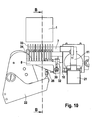
- FIG. 10 the essential components are shown in the rest position.
- the pressing means 8 is no longer in the interior of the wallet 1.
- This presentation can be particularly well the interlocked comb structures 33, 34 of bending means 7 and pressing means 8 refer.
- the vertical positions of folding 7 and pressing means 8 can be the sectional view along the line BB in FIG. 11 remove.
- the tip of the folding means 7 is below the tab 2.
- the drive means 22 for the pressing means 8 has its most remote from the wallet 1 position by the lever 12 is tilted about the pivot point 10 to the rear.
- the folding means 7 is moved upward about the pivot point 9, so that the tab 2 in a position after FIG. 5 is raised.
- the drive means 22 moves in the direction of the wallet 1, so that the lever 12 and thus the tip of the pressing means 8 is tilted towards the wallet 1 out.
- the movements of folding means 7 and pressing means 8 are coordinated so that the pressing means 8, the erected by the folding means 7 tab 2 into the interior of the wallet 1 transported in the in FIG. 9 shown position.
- FIG. 12 is now shown a working position, the of the FIG. 8 and Figure 9 corresponds, but adapted to a smaller tab 2.
- the pressing means 8 is arranged by means of the adjusting means 30 and the guide 32 remote from the wallet 1 than with larger tab geometries. This results in that the tip of the pressing means 8 no longer protrudes so far into the interior of the wallet 1 for pressing the tab 2.
- the length x2 between pivot point 9 and tip of the folding means 7 has been extended accordingly, so that the top of the tip of the Bending agent 7 relative to the surface has a reduced length x4.
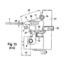
- FIG. 13 the section of the device is shown along the line CC in the small flap geometry pressing position x3.
- x2 changed by moving pressing means 8 along the lever 12 accordingly.
- X4 is adjusted by sliding a sliding block 15 on a slide 16 as shown FIG. 14 seen.
- the sectional view along the section line DD to FIG. 14 can be taken from the drive mechanism for the folding 7.
- a curve 18 is set in rotation.
- the curve 18 has a screw 20 with a certain inclination.
- On the right side of the screw 20 is enclosed by two cam rollers 17.
- a linear slide 16 is moved up and down.
- a sliding block 15 is adjustably mounted on the slider 16.
- a link rod 19 transmits the movement of the sliding block 15 on the lever 11.
- This lever 11 carries the folding means 7. As a result, the lever 11 is set in a pivoting movement about the pivot point 9.
- the device for folding at least one tab 2 of a package 1 works as follows. Wallet 1 enters the device. The glue head 6 carries the glue bead 5 on the tab 2. Then the transport movement stops. The folding means 7 edges the tab 2 by a little less than 90 ° upwards. The pressing means 8 then edges the tab 2 by more than 90 ° in the interior of the wallet 1 from. The pressing means 8 holds the tab 2 in this position. The glue 5 binds off. The pressing means 8 leaves the wallet 1 and pivots into the rest position, as well as the folding means 7. The wallet 1 leaves the station. At the same time the following Wallet 1 enters the station. From here, the sequence repeats as already described. The tab 2 is closed by only two tools, namely the folding means 7 and the pressing means 8.
- folding means 7 and pressing means 8 runs in opposite directions, that is, while the folding means 7, the flap 2 moves from bottom to top, the pressing means 8 in turn positioned the raised flap 2 by a movement from top to bottom inside the wallet 1.
- Die The chosen construction is characterized by high flexibility. For wallets 1 with different widths A only a single tool needs to be replaced, which is to be adapted to this width A.
- the pressing means 8 which conveys the tab 2 into the interior of the wallet 1.
- the folding means 7 is to be chosen so that it safely covers the maximum width A of the wallets 1 to be processed.
- the adjusting means 30, 32 serve to adapt the pressing means 8 to different tab heights x3.
- folding means 7 and / or pressing means 8 are displaceably connected to the respective levers 11, 12.
- the end position in working position x4 of the folding means 7 can be adjusted via the sliding block 15.
- the size x4 is adjusted so that x4 matches the tab length x3.
- the folding means 7 is moved on the lever 11 until the bending angle of the tab 2 is set to almost 90 °.
- the construction is also characterized by the fact that very flat wallets 1 can be processed with a short cover flap length x3. This is achieved in that comb structures 33, 34 are interlocked by folding means 7 and pressing means 8, respectively.
- folding means 7 and / or pressure means 8 can be driven by servomotors instead of curves.
- pivoting movements also linearly moving folding means 7 and / or pressing means 8 are conceivable.
- simpler tools could be produced, but the effort for the adjustment would be greater. In particular, the risk of collision of the tools is greater due to incorrect settings.
- a knife could be provided with an additional movement, which holds down the creasing edge between tab 3 and the associated base of the wallet 1. This could improve the process of Abkantens the tab 2 by the folding means 7.
- the knife must be during the bending be in the lower position by the folding means 7. Subsequently, it would have to be brought into the upper position when the pressing means 8 carries the tab inside the wallet 1. However, this knife runs the risk of coming into contact with the glue bead 5.
- the device described is particularly suitable for fixing blister 3 in wallets 1, but is not limited thereto. Thus, it generally serves the folding of at least one tab 2 in the interior of a package.
Landscapes
- Engineering & Computer Science (AREA)
- Mechanical Engineering (AREA)
- Absorbent Articles And Supports Therefor (AREA)
- Closing Of Containers (AREA)
- Purses, Travelling Bags, Baskets, Or Suitcases (AREA)
- Cartons (AREA)
- Auxiliary Devices For And Details Of Packaging Control (AREA)
- Making Paper Articles (AREA)
Description
- Die Erfindung geht aus von einer Vorrichtung zum Einfalten zumindest einer Lasche einer Verpackung nach der Gattung des Oberbegriffs des unabhangigen Anspruchs. Aus der
EP 1389 166 B1 ist bereits eine Vorrichtung zum Einschieben von Packgut in Packmittel, insbesondere von Blisterstreifen in Faltschachteln, bekannt. Nach Einschieben der Blister in die Faltschachtel wird diese in konventioneller Weise verschlossen. Diese Vorrichtung muss jedoch modifiziert werden, wenn anstelle in einer Faltschachtel Blisterstreifen in einer so genannten Wallet-Verpackung, einer in Form einer Brieftasche aufklappbaren und wieder verschließbaren Faltschachtel, aufbewahrt werden sollen. Es ist daher Aufgabe der Erfindung, eine solche Vorrichtung anzugeben und insbesondere darauf zu achten, dass sie leicht an unterschiedliche Verpackungsgrößen anzupassen ist. Diese Aufgabe wird durch die Merkmale des unabhängigen Anspruchs gelöst. - Aus der
EP-A-1020356 ist bereits eine gattungsgemäße Vorrichtung zum Fördern eines vorgefalteten Verpackungszuschnitts in einer Verpackungsmaschine bekannt. Hierbei sind in Förderrichtung des Verpackungszuschnitts im Bereich der Seitenwandabschnitte umlaufende Fördereinrichtungen angeordnet. Diese Fördereinrichtungen nehmen Mitnehmer auf, wobei jeweils ein Mitnehmerpaar einen der beiden Seitenwandabschnitte im Bereich der Stirnseiten dieses Seitenwandabschnitts zwischen sich fixiert. - Die erfindungsgemäße Vorrichtung zum Einfalten zumindest einer Lasche einer Verpackung gemäß den Merkmalen des unabhängigen Anspruchs hat demgegenüber den Vorteil, dass ein sicheres Fixieren des Blisters mit Hilfe einer so genannten Fixierlasche ermöglicht werden kann. Die Lasche wird nur mit zwei Werkzeugen, nämlich mit Abkantmittel und Andrückmittel, geschlossen. Insbesondere durch die Verwendung des Andrückmittels kann die Lasche so lange angedrückt werden, bis ein im vorangegangenen Schritt aufgebrachter Leim abgebunden hat. Zur Anpassung an unterschiedliche Breiten der Verpackung muss lediglich nur ein Werkzeug ausgetauscht werden. Das Abkantmittel muss nicht gewechselt werden, da es auf die breiteste Verpackung abgestimmt ist. Abkantmittel und/oder Andrückmitte weisen erfindungsgemäß eine Kammstruktur auf, wobei die Kammstrukturen von Abkantmittel und Andrückmittel vorzugsweise ineinander verzahnbar sind. Diese Struktur eignet sich insbesondere zum Umklappen besonders kurzer Laschen, wo Abkantmittel und Andrückmittel auf engem Raum auf die Lasche einwirken müssen.
- In einer zweckmäßigen Weiterbildung sind Antriebsmittel vorgesehen, die Abkantmittel und Andrückmittel so bewegen, dass die Lasche beim Abkanten in den Bewegungsbereich des Andrückmittels gelangt, welches die Lasche ins Innere der Verpackung bewegt und andrückt. Die Abtriebsbewegung der beiden Werkzeuge bleibt immer gleich, auch bei unterschiedlichen Geometrien der Verpackung mit Lasche.
- In einer zweckmäßigen Weiterbildung ist vorgesehen, dass das Abkantmittel die Lasche um ungefähr oder etwas weniger als 90° abkantet. Damit kann das Abkantmittel mit einer aufsteigenden oder absteigenden Bewegungsrichtung, das Andrückmittel entsprechend mit einer gegenläufigen, d.h. absteigenden oder aufsteigenden Bewegungsrichtung betrieben werden. Dadurch wird ein sicheres Umklappen der Lasche ins Innere der Verpackung erreicht.
- In einer zweckmäßigen Weiterbildung ist vorgesehen, dass Abkantmittel und/oder Andrückmittel über zumindest einen Hebel in eine Schwenkbewegung bringbar sind. In einer zweckmäßigen Weiterbildung ist vorgesehen, dass die Schwenkbewegung der Hebel durch Kurven erzeugbar sind. Diese Antriebsart zeichnet sich durch eine besonders einfache Bauart aus.
- In einer zweckmäßigen Weiterbildung ist vorgesehen, dass Abkantmittel und/oder Andrückmittel gegenüber dem Hebel verschiebbar angeordnet sind. Dadurch lassen sich besonders einfach Anpassungen an unterschiedliche Verpackungsgeometrien vornehmen.
- In einer zweckmäßigen Weiterbildung ist vorgesehen, dass zumindest ein Leimkopf vorgesehen ist, der Leim auf die Lasche aufträgt. Damit lässt sich in einer Baugruppe das sichere Verschließen oder Fixieren der Lasche vornehmen.
- Weitere zweckmäßige Weiterbildungen ergeben sich aus weiteren abhängigen Ansprüchen und aus der Beschreibung.
- Ein Ausführungsbeispiel der Vorrichtung zum Einfalten zumindest einer Lasche einer Verpackung ist in der Zeichnung dargestellt und wird nachfolgend näher beschrieben.
- Es zeigen:
- Figur 1
- eine Seitenansicht der Verpackung mit noch ausgeklappten Deckla- schen,
- Figur 2
- eine Seitenansicht der Verpackung bei eingeklappten Decklaschen,
- Figur 3
- eine perspektivische Ansicht der Verpackung,
- Figur 4
- die Verpackung mit ausgeklappter Seitenlasche beim Aufbringen des Leims,
- Figur 5
- eine schematische Darstellung der Vorrichtung beim Abkanten der Lasche,
- Figur 6
- eine schematische Darstellung der Vorrichtung beim Andrücken der Lasche,
- Figur 7
- eine perspektivische Darstellung der Vorrichtung,
- Figur 8
- die Draufsicht der Vorrichtung in einer ersten Arbeitsstellung,
- Figur 9
- den Querschnitt entlang des Linie A-A aus
Figur 8 , - Figur 10
- eine Draufsicht der Vorrichtung in der Ruhestellung,
- Figur 11
- einen Querschnitt entlang der Linie B-B gemäß
Figur 10 , - Figur 12
- eine Draufsicht auf die Vorrichtung in einer zweiten Arbeitsstellung,
- Figur 13
- einen Querschnitt entlang der Linie C-C nach
Figur 12 und - Figur 14
- einen Querschnitts entlang der Linie D-D nach
Figur 12 . - Bei der in
Figur 1 gezeigten Verpackung handelt es sich um ein so genanntes Wallet 1. Dieses Wallet 1 lässt sich wie eine Brieftasche auffalten und wieder verschließen. Es schützt einen darin fixierten Blister 3. Weiterhin ist eine Karte 4 vorgesehen mit Aussparungen in den Bereichen der Näpfe des Blisters 3. Diese Karte 4 überdeckt den Blister 3 wie inFigur 1 und Figur 2 dargestellt. Zur Fixierung des Blisters 3 mit dem Wallet 1 sind seitlich Laschen 2 beziehungsweise Decklaschen vorgesehen als Teil der das Wallet 1 bildenden Verpackung. Diese werden mit der später beschriebenen Vorrichtung zum Einfalten mittels Leim 5 mit der Karte 4 fixiert, so dass auch der zwischen Karte 4 und Boden des Wallets 1 befindliche Blister 3 fest mit dem Wallet 1 verbunden ist. An dem Boden des Wallets 1 können auf die Blisternäpfe abgestimmte Öffnungen oder Ausstanzungen vorgesehen sein. Über diese Öffnungen können in den Näpfen befindliche Gegenstände entnommen werden. Das Wallet 1 weist im Wesentlichen die Form einer konventionellen Faltschachtel auf. Allerdings kann das Wallet 1 beispielsweise über einen Klebeverschluss in Längsrichtung wieder verschließbar geöffnet werden. Zudem sind die Seiten entgegen einer konventionellen Faltschachtel nicht verschlossen, da die Laschen 2 nach innen eingeklappt werden, um den Blister 3 mittelbar oder unmittelbar mit dem Wallet 1 zu verbinden. - Das Wallet 1 hat eine Breite A wie in
Figur 3 angedeutet. Zum Befestigen des Blisters 3 mit dem Wallet 1 ist ein Leimkopf 6 vorgesehen, der einen Leim 5 auf die Oberseite der Lasche 2 aufträgt, vergleicheFigur 4 . - Diese Lasche 2 soll nun in das Innere des Wallets 1 eingefaltet werden. Hierzu befindet sich ein Abkantmittel 7 unterhalb der Lasche 2 wie in
Figur 5 gezeigt. Das Abkantmittel 7 wird über einen Hebel 11 um einen Drehpunkt 9 nach oben hin verschwenkt. Dabei wird die Lasche 2 zum Inneren des Wallets 1 hin in den Arbeitsbereich eines Andrückmittels 8 gebracht. Befindet sich die Seitenlasche 2 im Arbeitsbereich des Andrückmittels 8, wird dieses über den Hebel 12 um den Drehpunkt 10 hin zur Lasche 2 verschwenkt. GemäßFigur 6 ist der Arbeitsbereich des Andrückmittels 8 so gewählt, dass es die Lasche 2 bis ins Innere des Wallets 1 befördert. Dadurch wird die Lasche 2 mit nun nach unten weisendem Kleber 5 gegen die Karte 4 oder den Blister 3 gedrückt, wie inFigur 2 gezeigt. Die Vorrichtung zeichnet sich durch Einstellmöglichkeiten zumindest dreier Variablen aus. X1ist die Länge des Andrückmittels 8. Mit x2 wird die Länge des Hebels 11 des Abkantmittels 7 bezeichnet. X4 ist der Abstand zwischen Oberfläche des Wallets 1 und der Spitze des Abkantmittels 7 bei Erreichen seiner maximalen, oberen Vertikalposition. Mit x3 wird die Länge der (Deck)lasche 2 bezeichnet, auf die hin die Größen x1, x2 und x4 abzustimmen sind. - Gemäß
Figur 7 führt ein Transportsystem 13 in Laufrichtung 14 einen Wallet 1 zu, dessen Decklaschen 2 mit der auf einem Blister 3 liegenden Karte 4 verklebt werden sollen. Zuerst passiert das Wallet 1 einen Leimkopf 6, der Leim 5 auf die Oberseite der Lasche 2 aufbringt. Anschließend gelangt es in den Arbeitsbereich des Abkantmittels 7 und des Andrückmittels 8, wie nachfolgend näher beschrieben. - In der
Figur 7 ist eine Arbeitsstellung gezeigt, bei der das Andrückmittel 8 die zu verklebende Lasche 2 ins Innere des Wallets 1 drückt. Der Kopf des Andrückmittels 8 weist eine kammförmige Struktur 34 auf, die in Richtung des Inneren des Wallets 1 spitz ausläuft. Der Kopf des Andrückmittels 8 lässt sich über ein Einstellmittel 30 entlang einer Führung 32 verschieben, so dass über x1 eingestellt werden kann, wie weit das Andrückmittel 8 in das Innere des Wallets 1 ragt. Der Kopf des Andrückmittels 8 wird über einen Hebel 12 abgekippt, so dass der Kopf senkrecht zur Laufrichtung 14 in das Wallet 1 eingeführt und zurückgeführt werden kann. Die über einen Riemen 24 übertragene Bewegung setzt ein Antriebsmittel 22 über eine Koppelstange 26 in eine entsprechende Kippbewegung des Hebels 12 um. Der Riemen 24 verbindet das Antriebsmittel 22 des Andrückmittels 8 mit dem Antriebsmittel 21 für das Abkantmittel 7. Wie später noch ausführlicher gezeigt, wird die Bewegung des Antriebsmittels 21 in eine Kippbewegung des Hebels 11 umgesetzt, der in einem Drehpunkt 10 gelagert ist. Der Hebel 11 ist mit dem Kopf des Abkantmittels 7 verbunden, welcher ebenfalls eine Kammstruktur 33 aufweist, wobei die beiden Kammstrukturen 33, 34 ineinander greifen. - In der
Figur 8 sind die wesentlichen Komponenten derFigur 7 nochmals in der Draufsicht dargestellt, und zwar in der Arbeitsstellung derFigur 7 . Da die Komponenten derjenigen derFigur 7 entsprechen und mit denselben Bezugszeichen versehen sind, wird auf eine erneute Nennung verzichtet. In der Schnittdarstellung entlang der Linie A-A in derFigur 9 ist der Antriebsmechanismus ersichtlich. Das Antriebsmittel 22 für die Andrückmittel 8 führt eine Bewegung im Wesentlichen senkrecht zur Laufrichtung 14 aus. Diese Bewegung wird über die Koppelstange 26 auf den Hebel 12 im Sinne einer Schwenkbewegung in einer Ebene ermöglicht, deren Normalenvektor im Wesentlichen parallel ist zur Laufrichtung 14. Hierzu ist der Hebel 12 um den Drehpunkt 9 kippbar gelagert. Die Bewegung des Hebels 12 wird begrenzt durch die Koppelstange 26, deren anderes Ende in einem Drehpunkt 27 mit dem Hebel 12 drehbar verbunden ist. Dadurch wird die gewünschte Schwenkbewegung erzeugt. - Die korrespondierende Ruhestellung ist in den
Figuren 10 und11 gezeigt. Dort ist die Stellung des Antriebsmittels 22 so weit von dem Wallet 1 entfernt, dass der Hebel 12 die Spitze des Andrückmittels 8 so weit nach hinten abgeklappt hat, dass sie sich nicht mehr im Inneren des Wallets 1 befindet. -
Figur 9 lässt sich weiter gut entnehmen, dass die Unterseite des Andrückmittels 8 im Wesentlichen parallel zu der Innenseite des Wallets 1 die Lasche 2 andrückt. Das Abkantmittel 7 befindet sich noch in einer Position, in der sich die Lasche 2 im wesentlichen um beinahe 90° aufgerichtet hat, bevor das Andrückmittel 8 die so aufgerichtete Lasche 2 um weitere 90° in das Innere des Wallets 1 beförderte. Auch das Abkantmittel 7 wird über den Hebel 11 in eine Kippbewegung versetzt, wobei der Hebel 11 über den Drehpunkt 10 drehbar gelagert ist. Das Abkantmittel 7 kann vorzugsweise entlang der Längsachse des Hebels 11 verschoben werden, so dass dadurch die Länge x2 einstellbar wird und somit der Winkel, um den das Abkantmittel 7 die Lasche 2 abkantet, auf nahezu 90° einstellbar ist. - In
Figur 10 sind die wesentlichen Komponenten in der Ruheposition gezeigt. Insbesondere das Andrückmittel 8 befindet sich nicht mehr im Inneren des Wallets 1. Dieser Darstellung lassen sich besonders gut die ineinander verzahnten Kammstrukturen 33, 34 von Abkantmittel 7 und Andrückmittel 8 entnehmen. Insbesondere die vertikalen Positionen von Abkantmittel 7 und Andrückmittel 8 lassen sich der Schnittdarstellung entlang der Linie B-B inFigur 11 entnehmen. So befindet sich die Spitze des Abkantmittels 7 unterhalb der Lasche 2. Das Antriebsmittel 22 für das Andrückmittel 8 weist seine vom Wallet 1 entfernteste Position auf, indem der Hebel 12 um den Drehpunkt 10 nach hinten gekippt ist. Im folgenden Arbeitsgang wird das Abkantmittel 7 nach oben um den Drehpunkt 9 bewegt, so dass die Lasche 2 in eine Position nachFigur 5 aufgerichtet wird. Zudem bewegt sich das Antriebsmittel 22 in Richtung auf das Wallet 1 zu, so dass der Hebel 12 und damit die Spitze des Andrückmittels 8 zum Wallet 1 hin abgekippt wird. Die Bewegungen von Abkantmittel 7 und Andrückmittel 8 sind so aufeinander abgestimmt, dass das Andrückmittel 8 die vom Abkantmittel 7 aufgerichtete Lasche 2 ins Innere des Wallets 1 befördert in die inFigur 9 dargestellte Position. - Gemäß
Figur 12 ist nun eine Arbeitsstellung gezeigt, die der derFigur 8 und Figur 9 entspricht, allerdings angepasst auf eine kleinere Lasche 2. Das Andrückmittel 8 ist mit Hilfe des Einstellmittels 30 und der Führung 32 entfernter von dem Wallet 1 angeordnet als bei größeren Laschengeometrien. Dies führt dazu, dass die Spitze des Andrückmittels 8 nicht mehr so weit in das Innere des Wallets 1 hineinragt zum Andrücken der Lasche 2. Auch die Länge x2 zwischen Drehpunkt 9 und Spitze des Abkantmittels 7 wurde entsprechend verlängert, so dass die Oberseite der Spitze des Abkantmittels 7 gegenüber der Oberfläche eine reduzierte Länge x4 aufweist. - In
Figur 13 ist der Schnitt der Vorrichtung entlang der Linie C-C in der Andrückstellung für kleine Laschengeometrien x3 gezeigt. Im Vergleich zu der Einstellung beiFigur 9 wurde die Größe x2 durch Verschieben von Andrückmittel 8 entlang des Hebels 12 entsprechend verändert. X4 wird verstellt, indem ein Nutstein 15 auf einem Schieber 16 verschoben wird wie anhandFigur 14 ersichtlich. - Der Schnittdarstellung entlang der Schnittlinie D-D nach
Figur 14 lässt sich der Antriebsmechanismus für das Abkantmittel 7 entnehmen. Beispielsweise über den Riemen 24 wird eine Kurve 18 in Rotation versetzt. Die Kurve 18 weist einen Schraubengang 20 auf mit einer bestimmten Neigung. An der rechten Seite wird der Schraubengang 20 von zwei Kurvenrollen 17 umschlossen. Über diese Kurvenrollen 17 wird ein linear geführter Schieber 16 auf und ab bewegt. Ein Nutstein 15 ist verstellbar auf dem Schieber 16 befestigt. Eine Gelenkstange 19 überträgt die Bewegung des Nutsteins 15 auf den Hebel 11. Dieser Hebel 11 trägt das Abkantmittel 7. Dadurch wird der Hebel 11 in eine Schwenkbewegung um den Drehpunkt 9 versetzt. - Zusammenfassend funktioniert die Vorrichtung zum Einfalten zumindest einer Lasche 2 einer Verpackung 1 wie folgt. Das Wallet 1 fährt in die Vorrichtung ein. Dabei trägt der Leimkopf 6 die Leimraupe 5 auf die Lasche 2 auf. Dann stoppt die Transportbewegung. Das Abkantmittel 7 kantet die Lasche 2 um etwas weniger als 90° nach oben ab. Das Andrückmittel 8 kantet anschließend die Lasche 2 um mehr als 90° in das Innere des Wallets 1 ab. Das Andrückmittel 8 hält die Lasche 2 in dieser Position. Dabei bindet der Leim 5 ab. Das Andrückmittel 8 verlässt das Wallet 1 und schwenkt in die Ruhestellung, ebenso wie das Abkantmittel 7. Das Wallet 1 verlässt die Station. Gleichzeitig fährt das nachfolgende Wallet 1 in die Station ein. Ab hier wiederholt sich der Ablauf wie bereits beschrieben. Die Lasche 2 wird durch lediglich zwei Werkzeuge, nämlich das Abkantmittel 7 und das Andrückmittel 8, geschlossen. Die Bewegung von Abkantmittel 7 und Andrückmittel 8 verläuft gegenläufig, das heißt, während das Abkantmittel 7 die Lasche 2 von unten nach oben bewegt, positioniert das Andrückmittel 8 wiederum die angehobene Lasche 2 durch eine Bewegung von oben nach unten ins Innere des Wallets 1. Die gewählte Konstruktion zeichnet sich durch hohe Flexibilität aus. Bei Wallets 1 mit unterschiedlichen Breiten A muss lediglich ein einziges Werkzeug ausgetauscht werden, welches an diese Breite A anzupassen ist.
- Hierbei handelt es sich um das Andrückmittel 8, welches die Lasche 2 ins Innere des Wallets 1 befördert. Das Abkantmittel 7 ist so zu wählen, dass es sicher die maximale Breite A der zu verarbeitenden Wallets 1 umfasst.
- Wie bereits beschrieben, dienen die Einstellmittel 30, 32 dazu, die Andrückmittel 8 an unterschiedliche Laschenhöhen x3 anzupassen. Dies wird insbesondere erreicht, dass Abkantmittel 7 und/oder Andrückmittel 8 verschiebbar mit den jeweiligen Hebeln 11, 12 verbunden sind. Zudem lässt sich über den Nutstein 15 die Endlage in Arbeitsstellung x4 des Abkantmittels 7 einstellen. Durch Verstellung des Nutseins 15 auf dem Schieber 16 wird die Größe x4 so verstellt, dass x4 zur Laschenlänge x3 passt. Dadurch wird zwar auch die Endlage in Ruhestellung mit verschoben, was jedoch für die Funktion unerheblich ist. Anschließend wird das Abkantmittel 7 auf dem Hebel 11 verschoben, bis der Abkantwinkel der Lasche 2 auf nahezu 90° eingestellt ist. Die Konstruktion zeichnet sich auch dadurch aus, dass sehr flache Wallets 1 mit kurzer Decklaschenlänge x3 verarbeitet werden können. Dies wird dadurch erreicht, dass Kammstrukturen 33, 34 von Abkantmittel 7 bzw. Andrückmittel 8 ineinander verzahnt sind.
- In der Regel sind zwei Decklaschen 2 zu schließen. Zur Vereinfachung wurde jedoch nur eine Seite gezeigt.
- Dem Fachmann sind zahlreiche Abwandlungen geläufig, die Vorrichtung zu realisieren. So können Abkantmittel 7 und/oder Andrückmittel 8 anstelle mit Kurven auch über Servomotoren angetrieben werden. Anstelle der Schwenkbewegungen sind auch linear bewegte Abkantmittel 7 und/oder Andrückmittel 8 denkbar. Zwar ließen sich einfachere Werkzeuge herstellen, jedoch wäre der Aufwand für die Justierung größer. Insbesondere ist die Kollisionsgefahr der Werkzeuge durch Fehleinstellungen größer.
- Auch könnte ein Messer mit einer zusätzlichen Bewegung vorgesehen werden, welches die Rillkante zwischen Lasche 3 und damit verbundener Grundfläche des Wallets 1 niederhält. Dies könnte den Prozess des Abkantens der Lasche 2 durch das Abkantmittel 7 verbessern. Das Messer muss während der Abkantung durch das Abkantmittel 7 in unterer Position sein. Anschließend müsste es in die obere Position gebracht werden, wenn das Andrückmittel 8 die Lasche ins Innere des Wallets 1 befördert. Dieses Messer läuft allerdings Gefahr, mit der Leimraupe 5 in Kontakt zu kommen.
- Die beschriebene Vorrichtung eignet sich insbesondere zur Fixierung von Blister 3 in Wallets 1, ist jedoch hierauf nicht eingeschränkt. So dient sie allgemein dem Einklappen von zumindest einer Lasche 2 in den Innenraum einer Verpackung.
Claims (9)
- Vorrichtung zum Einfalten zumindest einer Lasche (2) einer Verpackung (1), umfassend Abkantmittel (7) zum Abkanten der zumindest einen Lasche (2) und Andrückmittel (8) zum Andrücken der Lasche (2), wobei die Andrückmittel (8) zum Andrücken der Lasche (2) ins Innere der Verpackung (1) hineinragen, dadurch gekennzeichnet, dass das Abkantmittel (7) und Andrückmittel (8) eine Kammstruktur (33, 34) aufweisen, wobei die Kammstrukturen (33, 34) von Abkantmittel (7) und Andrückmittel (8) ineinander verzahnbar sind.
- Vorrichtung nach Anspruch 1, dadurch gekennzeichnet, dass Antriebsmittel (21, 22) vorgesehen sind, die das Abkantmittel (7) und Andrückmittel (8) so bewegen, dass die Lasche (2) beim Abkanten in den Bewegungsbereich des Andrückmittels (8) gelangt, welches die Lasche (2) ins Innere der Verpackung (1) bewegt und andrückt.
- Vorrichtung nach einem der vorhergehenden Ansprüche, dadurch gekennzeichnet, dass das Abkantmittel (7) die Lasche (2) um ungefähr 90 Grad abkantet.
- Vorrichtung nach einem der vorhergehenden Ansprüche, dadurch gekennzeichnet, dass Abkantmittel (7) und/oder Andrückmittel (8) über zumindest einen Hebel (11, 12) in eine Schwenkbewegung bringbar sind.
- Vorrichtung nach Anspruch 4, dadurch gekennzeichnet, dass Abkantmittel (7) und/oder Andrückmittel (8) gegenüber dem Hebel (11,12) verschiebbar angeordnet sind.
- Vorrichtung nach einem der Ansprüche 4 und 5 dadurch gekennzeichnet, dass die Schwenkbewegung der Hebel (11, 12) durch Kurven (18, 20, 21, 22) erzeugbar sind.
- Vorrichtung nach einem der vorhergehenden Ansprüche, dadurch gekennzeichnet, dass zumindest ein Leimkopf (6) vorgesehen ist, der Leim (5) auf die Lasche (2) aufträgt.
- Vorrichtung nach einem der vorhergehenden Ansprüche 4-7, dadurch gekennzeichnet, dass ein Schieber (16) vorgesehen ist, dessen Auf- und Abwärtsbewegung über eine Gelenkstange (19) mechanisch mit dem Hebel (11) gekoppelt ist.
- Vorrichtung nach Anspruch 8, dadurch gekennzeichnet, dass die Verbindung zwischen Schieber (16) und Gelenkstange (19) über einen Nutstein (15) vorgenommen ist.
Applications Claiming Priority (2)
| Application Number | Priority Date | Filing Date | Title |
|---|---|---|---|
| DE102006020519A DE102006020519A1 (de) | 2006-05-03 | 2006-05-03 | Vorrichtung zum Einfalten zumindest einer Lasche einer Verpackung |
| PCT/EP2007/053577 WO2007125016A1 (de) | 2006-05-03 | 2007-04-12 | Vorrichtung zum einfalten zumindest einer lasche einer verpackung |
Publications (2)
| Publication Number | Publication Date |
|---|---|
| EP2015995A1 EP2015995A1 (de) | 2009-01-21 |
| EP2015995B1 true EP2015995B1 (de) | 2010-12-01 |
Family
ID=38162295
Family Applications (1)
| Application Number | Title | Priority Date | Filing Date |
|---|---|---|---|
| EP07728044A Not-in-force EP2015995B1 (de) | 2006-05-03 | 2007-04-12 | Vorrichtung zum einfalten zumindest einer lasche einer verpackung |
Country Status (5)
| Country | Link |
|---|---|
| US (1) | US20090183467A1 (de) |
| EP (1) | EP2015995B1 (de) |
| AT (1) | ATE490183T1 (de) |
| DE (2) | DE102006020519A1 (de) |
| WO (1) | WO2007125016A1 (de) |
Families Citing this family (5)
| Publication number | Priority date | Publication date | Assignee | Title |
|---|---|---|---|---|
| DE102008052633A1 (de) * | 2008-10-22 | 2010-04-29 | Khs Ag | Verfahren und Vorrichtung zur Herstellung einer Verpackungseinheit |
| US9003747B2 (en) * | 2012-04-23 | 2015-04-14 | Alain Cerf | Process and apparatus for increasing stacking strength of film wrapped articles |
| DE102019120788A1 (de) * | 2019-08-01 | 2021-02-04 | Khs Gmbh | Vorrichtung sowie Verfahren für die Herstellung von Gebinden aus Einzelpackungen |
| CN112158401A (zh) * | 2020-09-07 | 2021-01-01 | 西安工程大学 | 一种摆动式袜子腰封自动折纸装置 |
| CN112224475B (zh) * | 2020-09-30 | 2025-05-09 | 宏泰机电科技(漳州)有限公司 | 一种包装盒自动合盖设备 |
Family Cites Families (8)
| Publication number | Priority date | Publication date | Assignee | Title |
|---|---|---|---|---|
| SE7810947L (sv) * | 1978-10-20 | 1980-04-21 | Draco Ab | 3-alkylxanthines |
| US4584818A (en) * | 1985-08-20 | 1986-04-29 | Frito-Lay, Inc. | Apparatus for automatically closing L-slide lock cartons |
| DE19901238B4 (de) | 1999-01-14 | 2005-12-08 | Seidel, Helmut | Vorrichtung zum Fördern eines vorgefalteten Verpackungszuschnittes in einer Verpackungsmaschine |
| DE19918940B4 (de) * | 1999-04-27 | 2005-07-07 | Uhlmann Pac-Systeme Gmbh & Co Kg | Vorrichtung zum Verschließen einer Faltschachtel |
| DE19953122A1 (de) * | 1999-11-04 | 2001-05-23 | Kloeckner Medipak Gmbh | Verfahren und Vorrichtung zum Verschließen einer Faltschachtel |
| SE517051C2 (sv) * | 1999-12-10 | 2002-04-09 | Tetra Laval Holdings & Finance | Kontinuerlig anordning vid en distributionsutrustning |
| DE10123217A1 (de) * | 2001-05-12 | 2002-11-28 | Bosch Gmbh Robert | Vorrichtung zum Einschieben von Packgut in Packmittel |
| DE10347520A1 (de) * | 2003-10-13 | 2005-05-19 | Uhlmann Pac-Systeme Gmbh & Co. Kg | Schließstation |
-
2006
- 2006-05-03 DE DE102006020519A patent/DE102006020519A1/de not_active Withdrawn
-
2007
- 2007-04-12 AT AT07728044T patent/ATE490183T1/de active
- 2007-04-12 US US12/299,384 patent/US20090183467A1/en not_active Abandoned
- 2007-04-12 WO PCT/EP2007/053577 patent/WO2007125016A1/de not_active Ceased
- 2007-04-12 DE DE502007005849T patent/DE502007005849D1/de active Active
- 2007-04-12 EP EP07728044A patent/EP2015995B1/de not_active Not-in-force
Also Published As
| Publication number | Publication date |
|---|---|
| DE502007005849D1 (de) | 2011-01-13 |
| WO2007125016A1 (de) | 2007-11-08 |
| ATE490183T1 (de) | 2010-12-15 |
| US20090183467A1 (en) | 2009-07-23 |
| DE102006020519A1 (de) | 2007-11-08 |
| EP2015995A1 (de) | 2009-01-21 |
Similar Documents
| Publication | Publication Date | Title |
|---|---|---|
| EP2748069B1 (de) | Füllmaschine zum abfüllen von produkten in packungsbehälter sowie verfahren hierzu | |
| DE2536973C3 (de) | Vorrichtung zum Schließen der Bodenfaltung von Verpackungen | |
| DE102015118200A1 (de) | Pressenvorrichtung mit einstellmechanismus | |
| EP0022122A1 (de) | Biegemaschine | |
| DE60002213T2 (de) | Vorrichtung zum falten von laschen an schachtelähnlichen behältern | |
| DE60201425T2 (de) | Verfahren und vorrichtung zum schliessen einer schachtel durch falten einer lateralen schliessklappe | |
| EP0433657A1 (de) | Verfahren und Vorrichtung zum Herstellen von (Zigaretten-) Packungen | |
| DE10206773C1 (de) | Vorrichtung zum Vorschieben von Werkstücken mit Greiferschienen | |
| DE2816235A1 (de) | Geraet zum zusammenklappen von schachtelzuschnitten | |
| EP2015995A1 (de) | Vorrichtung zum einfalten zumindest einer lasche einer verpackung | |
| EP3566985B1 (de) | Trayabstapelvorrichtung mit entlastungseinrichtung | |
| EP1717147A1 (de) | Verfahren und Vorrichtung zum Schließen einer Faltschachtel während ihrer kontinuierlichen Förderung | |
| DE602005003155T2 (de) | Vorrichtung zum Herstellen von Schachteln | |
| DE2930191A1 (de) | Vorrichtung zum formen und schliessen von faltschachteln | |
| EP3515625A1 (de) | Werkzeug und werkzeugmaschine sowie verfahren zum bearbeiten von plattenförmigen werkstücken | |
| EP1097802A2 (de) | Verfahren und Vorrichtung zum Verschliessen einer Faltschachtel | |
| EP0025547B1 (de) | Vorrichtung zum Einfalten der Bodenklappen einer Faltschachtel | |
| EP0567769B1 (de) | Vorrichtung zum Einfalten des Bodens einer Kartonpackung | |
| DE69813359T2 (de) | Wendevorrichtung für eine Frontplatte in einer Falt-Beleimungsvorrichtung | |
| DE112006000668T5 (de) | Vorrichtung und Verfahren zum manuellen Falten eines Verpackungszuschnitts | |
| EP3744515B1 (de) | Vorrichtung und verfahren zum falten eines polsterteils | |
| DE69900923T2 (de) | Verfahren und Vorrichtung zum Trennen von Bindestreifen von Stapeln oder Packungen von Etiketten oder Zuschnitten | |
| DE10114044B4 (de) | Vorrichtung zum Führen eines in eine Transporteinrichtung einzulegenden Körpers | |
| DE19647277C2 (de) | Verschließeinrichtung für eine Verpackungsmaschine | |
| DE602006000420T2 (de) | Eine Maschine zur Verpackung von Produkten in Kartons |
Legal Events
| Date | Code | Title | Description |
|---|---|---|---|
| PUAI | Public reference made under article 153(3) epc to a published international application that has entered the european phase |
Free format text: ORIGINAL CODE: 0009012 |
|
| 17P | Request for examination filed |
Effective date: 20081203 |
|
| AK | Designated contracting states |
Kind code of ref document: A1 Designated state(s): AT BE BG CH CY CZ DE DK EE ES FI FR GB GR HU IE IS IT LI LT LU LV MC MT NL PL PT RO SE SI SK TR |
|
| AX | Request for extension of the european patent |
Extension state: AL BA HR MK RS |
|
| 17Q | First examination report despatched |
Effective date: 20090930 |
|
| GRAP | Despatch of communication of intention to grant a patent |
Free format text: ORIGINAL CODE: EPIDOSNIGR1 |
|
| GRAS | Grant fee paid |
Free format text: ORIGINAL CODE: EPIDOSNIGR3 |
|
| GRAA | (expected) grant |
Free format text: ORIGINAL CODE: 0009210 |
|
| AK | Designated contracting states |
Kind code of ref document: B1 Designated state(s): AT BE BG CH CY CZ DE DK EE ES FI FR GB GR HU IE IS IT LI LT LU LV MC MT NL PL PT RO SE SI SK TR |
|
| REG | Reference to a national code |
Ref country code: GB Ref legal event code: FG4D Free format text: NOT ENGLISH |
|
| REG | Reference to a national code |
Ref country code: CH Ref legal event code: EP |
|
| REG | Reference to a national code |
Ref country code: IE Ref legal event code: FG4D |
|
| REF | Corresponds to: |
Ref document number: 502007005849 Country of ref document: DE Date of ref document: 20110113 Kind code of ref document: P |
|
| REG | Reference to a national code |
Ref country code: NL Ref legal event code: VDEP Effective date: 20101201 |
|
| PG25 | Lapsed in a contracting state [announced via postgrant information from national office to epo] |
Ref country code: LT Free format text: LAPSE BECAUSE OF FAILURE TO SUBMIT A TRANSLATION OF THE DESCRIPTION OR TO PAY THE FEE WITHIN THE PRESCRIBED TIME-LIMIT Effective date: 20101201 |
|
| LTIE | Lt: invalidation of european patent or patent extension |
Effective date: 20101201 |
|
| PG25 | Lapsed in a contracting state [announced via postgrant information from national office to epo] |
Ref country code: FI Free format text: LAPSE BECAUSE OF FAILURE TO SUBMIT A TRANSLATION OF THE DESCRIPTION OR TO PAY THE FEE WITHIN THE PRESCRIBED TIME-LIMIT Effective date: 20101201 Ref country code: CY Free format text: LAPSE BECAUSE OF FAILURE TO SUBMIT A TRANSLATION OF THE DESCRIPTION OR TO PAY THE FEE WITHIN THE PRESCRIBED TIME-LIMIT Effective date: 20101201 Ref country code: SE Free format text: LAPSE BECAUSE OF FAILURE TO SUBMIT A TRANSLATION OF THE DESCRIPTION OR TO PAY THE FEE WITHIN THE PRESCRIBED TIME-LIMIT Effective date: 20101201 Ref country code: NL Free format text: LAPSE BECAUSE OF FAILURE TO SUBMIT A TRANSLATION OF THE DESCRIPTION OR TO PAY THE FEE WITHIN THE PRESCRIBED TIME-LIMIT Effective date: 20101201 Ref country code: LV Free format text: LAPSE BECAUSE OF FAILURE TO SUBMIT A TRANSLATION OF THE DESCRIPTION OR TO PAY THE FEE WITHIN THE PRESCRIBED TIME-LIMIT Effective date: 20101201 Ref country code: BG Free format text: LAPSE BECAUSE OF FAILURE TO SUBMIT A TRANSLATION OF THE DESCRIPTION OR TO PAY THE FEE WITHIN THE PRESCRIBED TIME-LIMIT Effective date: 20110301 Ref country code: SI Free format text: LAPSE BECAUSE OF FAILURE TO SUBMIT A TRANSLATION OF THE DESCRIPTION OR TO PAY THE FEE WITHIN THE PRESCRIBED TIME-LIMIT Effective date: 20101201 |
|
| REG | Reference to a national code |
Ref country code: IE Ref legal event code: FD4D |
|
| PG25 | Lapsed in a contracting state [announced via postgrant information from national office to epo] |
Ref country code: GR Free format text: LAPSE BECAUSE OF FAILURE TO SUBMIT A TRANSLATION OF THE DESCRIPTION OR TO PAY THE FEE WITHIN THE PRESCRIBED TIME-LIMIT Effective date: 20110302 |
|
| PG25 | Lapsed in a contracting state [announced via postgrant information from national office to epo] |
Ref country code: IE Free format text: LAPSE BECAUSE OF FAILURE TO SUBMIT A TRANSLATION OF THE DESCRIPTION OR TO PAY THE FEE WITHIN THE PRESCRIBED TIME-LIMIT Effective date: 20101201 Ref country code: ES Free format text: LAPSE BECAUSE OF FAILURE TO SUBMIT A TRANSLATION OF THE DESCRIPTION OR TO PAY THE FEE WITHIN THE PRESCRIBED TIME-LIMIT Effective date: 20110312 Ref country code: PT Free format text: LAPSE BECAUSE OF FAILURE TO SUBMIT A TRANSLATION OF THE DESCRIPTION OR TO PAY THE FEE WITHIN THE PRESCRIBED TIME-LIMIT Effective date: 20110401 Ref country code: EE Free format text: LAPSE BECAUSE OF FAILURE TO SUBMIT A TRANSLATION OF THE DESCRIPTION OR TO PAY THE FEE WITHIN THE PRESCRIBED TIME-LIMIT Effective date: 20101201 Ref country code: IS Free format text: LAPSE BECAUSE OF FAILURE TO SUBMIT A TRANSLATION OF THE DESCRIPTION OR TO PAY THE FEE WITHIN THE PRESCRIBED TIME-LIMIT Effective date: 20110401 Ref country code: CZ Free format text: LAPSE BECAUSE OF FAILURE TO SUBMIT A TRANSLATION OF THE DESCRIPTION OR TO PAY THE FEE WITHIN THE PRESCRIBED TIME-LIMIT Effective date: 20101201 |
|
| PG25 | Lapsed in a contracting state [announced via postgrant information from national office to epo] |
Ref country code: SK Free format text: LAPSE BECAUSE OF FAILURE TO SUBMIT A TRANSLATION OF THE DESCRIPTION OR TO PAY THE FEE WITHIN THE PRESCRIBED TIME-LIMIT Effective date: 20101201 Ref country code: RO Free format text: LAPSE BECAUSE OF FAILURE TO SUBMIT A TRANSLATION OF THE DESCRIPTION OR TO PAY THE FEE WITHIN THE PRESCRIBED TIME-LIMIT Effective date: 20101201 Ref country code: PL Free format text: LAPSE BECAUSE OF FAILURE TO SUBMIT A TRANSLATION OF THE DESCRIPTION OR TO PAY THE FEE WITHIN THE PRESCRIBED TIME-LIMIT Effective date: 20101201 |
|
| PLBE | No opposition filed within time limit |
Free format text: ORIGINAL CODE: 0009261 |
|
| STAA | Information on the status of an ep patent application or granted ep patent |
Free format text: STATUS: NO OPPOSITION FILED WITHIN TIME LIMIT |
|
| BERE | Be: lapsed |
Owner name: ROBERT BOSCH G.M.B.H. Effective date: 20110430 |
|
| PG25 | Lapsed in a contracting state [announced via postgrant information from national office to epo] |
Ref country code: DK Free format text: LAPSE BECAUSE OF FAILURE TO SUBMIT A TRANSLATION OF THE DESCRIPTION OR TO PAY THE FEE WITHIN THE PRESCRIBED TIME-LIMIT Effective date: 20101201 |
|
| 26N | No opposition filed |
Effective date: 20110902 |
|
| PG25 | Lapsed in a contracting state [announced via postgrant information from national office to epo] |
Ref country code: MC Free format text: LAPSE BECAUSE OF NON-PAYMENT OF DUE FEES Effective date: 20110430 |
|
| REG | Reference to a national code |
Ref country code: CH Ref legal event code: PL |
|
| REG | Reference to a national code |
Ref country code: DE Ref legal event code: R097 Ref document number: 502007005849 Country of ref document: DE Effective date: 20110902 |
|
| PG25 | Lapsed in a contracting state [announced via postgrant information from national office to epo] |
Ref country code: MT Free format text: LAPSE BECAUSE OF FAILURE TO SUBMIT A TRANSLATION OF THE DESCRIPTION OR TO PAY THE FEE WITHIN THE PRESCRIBED TIME-LIMIT Effective date: 20101201 |
|
| REG | Reference to a national code |
Ref country code: FR Ref legal event code: ST Effective date: 20111230 |
|
| PG25 | Lapsed in a contracting state [announced via postgrant information from national office to epo] |
Ref country code: FR Free format text: LAPSE BECAUSE OF NON-PAYMENT OF DUE FEES Effective date: 20110502 Ref country code: BE Free format text: LAPSE BECAUSE OF NON-PAYMENT OF DUE FEES Effective date: 20110430 Ref country code: CH Free format text: LAPSE BECAUSE OF NON-PAYMENT OF DUE FEES Effective date: 20110430 Ref country code: LI Free format text: LAPSE BECAUSE OF NON-PAYMENT OF DUE FEES Effective date: 20110430 |
|
| PG25 | Lapsed in a contracting state [announced via postgrant information from national office to epo] |
Ref country code: LU Free format text: LAPSE BECAUSE OF NON-PAYMENT OF DUE FEES Effective date: 20110412 |
|
| REG | Reference to a national code |
Ref country code: AT Ref legal event code: MM01 Ref document number: 490183 Country of ref document: AT Kind code of ref document: T Effective date: 20120412 |
|
| PG25 | Lapsed in a contracting state [announced via postgrant information from national office to epo] |
Ref country code: AT Free format text: LAPSE BECAUSE OF NON-PAYMENT OF DUE FEES Effective date: 20120412 |
|
| PG25 | Lapsed in a contracting state [announced via postgrant information from national office to epo] |
Ref country code: TR Free format text: LAPSE BECAUSE OF FAILURE TO SUBMIT A TRANSLATION OF THE DESCRIPTION OR TO PAY THE FEE WITHIN THE PRESCRIBED TIME-LIMIT Effective date: 20101201 |
|
| PG25 | Lapsed in a contracting state [announced via postgrant information from national office to epo] |
Ref country code: HU Free format text: LAPSE BECAUSE OF FAILURE TO SUBMIT A TRANSLATION OF THE DESCRIPTION OR TO PAY THE FEE WITHIN THE PRESCRIBED TIME-LIMIT Effective date: 20101201 |
|
| PGFP | Annual fee paid to national office [announced via postgrant information from national office to epo] |
Ref country code: GB Payment date: 20160422 Year of fee payment: 10 |
|
| PGFP | Annual fee paid to national office [announced via postgrant information from national office to epo] |
Ref country code: IT Payment date: 20160422 Year of fee payment: 10 |
|
| PGFP | Annual fee paid to national office [announced via postgrant information from national office to epo] |
Ref country code: DE Payment date: 20160628 Year of fee payment: 10 |
|
| REG | Reference to a national code |
Ref country code: DE Ref legal event code: R119 Ref document number: 502007005849 Country of ref document: DE |
|
| GBPC | Gb: european patent ceased through non-payment of renewal fee |
Effective date: 20170412 |
|
| PG25 | Lapsed in a contracting state [announced via postgrant information from national office to epo] |
Ref country code: DE Free format text: LAPSE BECAUSE OF NON-PAYMENT OF DUE FEES Effective date: 20171103 |
|
| PG25 | Lapsed in a contracting state [announced via postgrant information from national office to epo] |
Ref country code: GB Free format text: LAPSE BECAUSE OF NON-PAYMENT OF DUE FEES Effective date: 20170412 |
|
| PG25 | Lapsed in a contracting state [announced via postgrant information from national office to epo] |
Ref country code: IT Free format text: LAPSE BECAUSE OF NON-PAYMENT OF DUE FEES Effective date: 20170412 |