EP2014990B1 - Gargerät mit einer gargerätebedienvorrichtung - Google Patents
Gargerät mit einer gargerätebedienvorrichtung Download PDFInfo
- Publication number
- EP2014990B1 EP2014990B1 EP08104516.3A EP08104516A EP2014990B1 EP 2014990 B1 EP2014990 B1 EP 2014990B1 EP 08104516 A EP08104516 A EP 08104516A EP 2014990 B1 EP2014990 B1 EP 2014990B1
- Authority
- EP
- European Patent Office
- Prior art keywords
- cooking appliance
- control
- appliance according
- panel
- control panel
- Prior art date
- Legal status (The legal status is an assumption and is not a legal conclusion. Google has not performed a legal analysis and makes no representation as to the accuracy of the status listed.)
- Active
Links
Images
Classifications
-
- F—MECHANICAL ENGINEERING; LIGHTING; HEATING; WEAPONS; BLASTING
- F24—HEATING; RANGES; VENTILATING
- F24C—DOMESTIC STOVES OR RANGES ; DETAILS OF DOMESTIC STOVES OR RANGES, OF GENERAL APPLICATION
- F24C7/00—Stoves or ranges heated by electric energy
- F24C7/08—Arrangement or mounting of control or safety devices
- F24C7/082—Arrangement or mounting of control or safety devices on ranges, e.g. control panels, illumination
-
- A—HUMAN NECESSITIES
- A47—FURNITURE; DOMESTIC ARTICLES OR APPLIANCES; COFFEE MILLS; SPICE MILLS; SUCTION CLEANERS IN GENERAL
- A47L—DOMESTIC WASHING OR CLEANING; SUCTION CLEANERS IN GENERAL
- A47L15/00—Washing or rinsing machines for crockery or tableware
- A47L15/42—Details
- A47L15/4293—Arrangements for programme selection, e.g. control panels; Indication of the selected programme, programme progress or other parameters of the programme, e.g. by using display panels
-
- D—TEXTILES; PAPER
- D06—TREATMENT OF TEXTILES OR THE LIKE; LAUNDERING; FLEXIBLE MATERIALS NOT OTHERWISE PROVIDED FOR
- D06F—LAUNDERING, DRYING, IRONING, PRESSING OR FOLDING TEXTILE ARTICLES
- D06F34/00—Details of control systems for washing machines, washer-dryers or laundry dryers
- D06F34/28—Arrangements for program selection, e.g. control panels therefor; Arrangements for indicating program parameters, e.g. the selected program or its progress
Definitions
- the invention is based on a cooking appliance with a cooking appliance control device according to the preamble of claim 1.
- the DE 10 2005 049 802 A1 shows a household appliance operating device with a touch-sensitive, ring-shaped sensor field which comprises at least two sensor surfaces arranged around a center for detecting an angle ( ⁇ ) of a contact point (P).
- ⁇ an angle
- P a contact point
- the at least two sensor surfaces are designed to interlock in at least one angular range in the circumferential direction with respect to the center of the sensor field.
- the object of the invention is, in particular, to provide a cooking appliance with a device of the generic type which can advantageously be operated. According to the invention, the object is achieved by the features of the independent patent claim, while advantageous embodiments and developments of the invention can be found in the subclaims.
- the invention is based on a cooking appliance with a cooking appliance control device which has a control panel and a control panel.
- control panel is at least essentially flush with an upper and / or a lower outer edge of the control panel in at least one area.
- a "control panel” should be understood to mean a cover and / or in particular a front part of a domestic appliance in which a control panel with control elements is integrated and which in particular has one or more recesses for control elements of a control panel.
- a “control element” can be from different elements appearing to be useful to a person skilled in the art, such as in particular a control knob or, particularly advantageously, a control button, etc.
- a “control panel” is to be understood in particular as a field with associated control elements spatial arrangement can result. In particular, a maximum distance between directly adjacent control elements is less than 5 cm and particularly advantageously less than 2 cm.
- an “outer edge” should also be understood to mean an edge delimiting the control panel outwardly, in particular the edge next to it the control panel is arranged, and an edge of a recess completely enclosed by the control panel is to be excluded.
- “essentially” in this context is to be understood in particular that the control panel has a distance from an upper and / or lower outer edge of less than 5% and advantageously less than 1% of a height of the control panel in this area and particularly advantageously none Has distance.
- the individual operating elements can be made advantageously large despite a clear overall structure, in particular if the operating panel has at least two operating elements arranged one above the other or in the direction of a vertical extension and essentially directly adjoining one another.
- “essentially directly adjoining one another” is to be understood as meaning that the operating elements have a spacing in the direction of the vertical extension of less than 10 mm, advantageously less than 5 mm and particularly advantageously less than 2 mm.
- control panel has a height of less than 100 mm and advantageously less than 80 mm in at least one area and, particularly advantageously, a height of between 70 mm and 50 mm.
- a “height” is to be understood in particular as a front surface height formed by the control panel, which in particular runs in the vertical direction.
- a particularly clear and therefore particularly advantageously operable domestic appliance control device can be achieved through a corresponding configuration.
- the domestic appliance control device has a one-piece user interface means which forms at least part of a user interface of a first control element and a second control element.
- An at least substantially jointless structure can advantageously be achieved by means of a corresponding configuration and, in a passive state, it can advantageously be achieved that symbols applied to the control elements are particularly advantageously recognized and a disruptive control element profile or button profile is avoided.
- the user interface means can be formed by various means that appear sensible to a person skilled in the art, but particularly advantageously by a control film that can be made simple, inexpensive and robust.
- the domestic appliance control device has at least one control element with a symbol arranged in the control panel, the width of which extends at least over 80% of a control element width of the control element and / or the height of which extends over at least 80% of a control element height of the control element , whereby the clarity can be further improved and the operation can be further simplified, in particular if at least a large part of the operating elements has corresponding symbols.
- the domestic appliance control device has a display arranged above the control panel, operation can advantageously be supported by the display and the display can be prevented from being covered by an operator even during operation.
- the display can have a length that is less than or equal to a length of the control panel or, particularly advantageously, that is longer than a length of the control panel.
- control panel has at least two, preferably at least three and particularly preferably at least four control elements arranged one behind the other in a reading direction, which are to be operated one after the other according to their arrangement in the reading direction with at least one control logic.
- a “reading direction” is to be understood in a basic operating position, such as in particular in a position with a viewing direction essentially perpendicular to a front side from the front, from left to right.
- an “operating logic” is to be understood as meaning, in particular, a sensible and, in particular, recommended sequence of actuation of operating elements.
- An advantageously self-explanatory operation can be achieved through a corresponding arrangement.
- one end of the control panel is preferably formed by a main switch, specifically preferably a left end when viewed in a basic operating position.
- a “main switch” should be understood to mean in particular a switch for switching on and / or off.
- the operation can be simplified if the domestic appliance operating device has at least one signal means which is used to acknowledge an actuation of an operating element is provided, particularly preferably when the signal means is arranged in a surface area of an operating element assigned to it.
- the signal means has a slit-shaped configuration and / or if the signal means forms at least part of a frame of an operating element, this can be positioned particularly advantageously in a space-saving and easily visible manner.
- a “slot-shaped configuration” should in particular be understood to mean that the signal means has a length that is at least three times and preferably at least five times greater than its width.
- a “frame” should be understood in particular to mean that the signaling means laterally delimits the operating element, specifically particularly preferably over at least 30% of its projected circumference. If the signaling means forms a guide for an operating element, additional components, installation space, installation effort and costs can be saved.
- the signal means be at least partially formed in one piece with a sensor means, whereby additional components, installation space, assembly effort and costs can also be saved.
- control panel forms at least part of a side frame of a household appliance door.
- a “side frame” is to be understood as meaning, in particular, a frame which laterally delimits the domestic appliance door, viewed in a horizontal direction, parallel to a front side.
- main program operating elements in the case of cooking appliance operating devices are to be understood as meaning, in particular, type of heating operating elements for selecting different heating elements, such as upper heat, lower heat, circulating air, grill and combinations thereof.
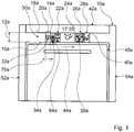
- Fig. 1 shows a front view of a schematically illustrated cooking appliance with a cooking appliance control device.
- the cooking appliance control device comprises an H-shaped control panel 10a made of stainless steel with a transverse limb 50a with a control panel 14a integrated therein and two vertically extending limbs 52a, 54a which form a side frame of a household appliance door 48a of the cooking appliance or laterally delimit the household appliance door 48a.
- the transverse leg 50a of the control panel 10a has a height 12a of approximately 60 mm.
- the control panel 14a has the same height as the transverse limb 50a and terminates over its entire length with a lower outer edge 16a and an upper outer edge 18a of the transverse limb 50a, which means that operating elements 20a-28a are particularly large and can be easily grasped optically and tactilely by an operator can be.
- the control panel 14a has the control elements 20a-28a arranged one behind the other in a reading direction 44a from left to right, which are to be actuated one after the other according to the arrangement from left to right with a recommended control logic.
- a left end of the control panel 14a is formed by the control element 20a designed as a control button, which extends over the entire height 12a of the control panel 10a and forms a main switch for switching the cooking appliance on and off.
- the operating element 20a is directly adjoined in the reading direction 44a by a function block with the four operating elements 22a designed as operating keys, which are arranged in two rows one above the other and which are arranged in two rows next to one another directly adjacent to one another.
- the operating elements 22a of the function block form main program operating elements, which are provided to select different types of heating, specifically in the present case the type of heating combined with upper heat, convection, grill and grill combined with convection.
- the function block is followed by the operating element 24a formed by a rotary knob, which is provided in particular for setting a temperature.
- the control element 24a is followed in the reading direction 44a by a control block with the four control elements 26a designed as control buttons, by means of which an alarm time or a time until an alarm, a time, an oven duration and an end time can be set.
- the operating elements 26a are arranged, corresponding to the operating elements 22a, in two rows next to one another and in two rows one above the other directly adjoining one another.
- control block with the control elements 26a is followed in the reading direction 44a by the control element 28a, which is provided to start a selected process and which, in accordance with the control element 20a, extends over the entire height 12a of the control panel 10a.
- the control element 28a forms the right end of the control panel 14a.
- the cooking appliance is first switched on at the operating element 20a, then a corresponding type of heating is selected via the operating elements 22a of the function block. A corresponding temperature is then set on the control element 24a, a baking time is set by means of the control elements 26a of the control block and the selected process is then started by means of the control element 28a.
- a strip-shaped display 42a is arranged, which has the same length as the transverse leg 50a and extends laterally beyond the control panel 14a due to its greater length than the control panel 14a.
- the display 42a is provided in particular to display selected types of heating by means of a text and a symbol.
- the cooking appliance operating device comprises signaling means 46a which are provided for acknowledging an actuation of the operating elements 20a, 22a, 26a, 28a ( Figure 2 ).
- Each signal means 46a is arranged in a surface area of an operating element 20a-28a assigned to it.
- the signal means 46a are slit-shaped and designed in one piece with the sensor means, in that they are provided to transmit sensor radiation, specifically in that they are designed to be permeable to sensor rays formed by infrared radiation.
- the operating elements 20a, 22a, 26a, 28a each have symbols 32a, 34a, 38a, 40a, which each extend over approximately 90% of an operating element width 70a.
- the signaling means 46a is arranged within the symbol 32a, while in the case of the operating elements 22a, 26a, 28a, the signaling means 46a are each arranged in the area of the operating elements 22a, 26a, 28a, directly below the symbols 34a, 38a, 40a.
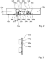
- FIG 2 shows an alternative cooking appliance control device with a U-shaped control panel 10b.
- a control panel 14b is integrated in a lower transverse limb 56b of the control panel 10b and has the same length as the transverse limb 56b.
- the transverse limb 56b of the control panel 10b has a height 12b of approximately 60 mm.
- a display 42b is arranged on the control panel 14b and has the same length as the transverse limb 56b or as the control panel 14b.
- the control panel 14b has a one-piece control surface means 30b, which, apart from a control element 24b formed by a rotary knob, forms a control surface 66b for all control elements 20b, 22b, 26b, 28b, on which symbols 32b, 34b, 38b, 40b are arranged.
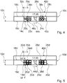
- the user interface means 30b is formed by a control film ( Figure 3 ).
- a control element width 70b is formed from a respective symbol width and a control element height from a respective symbol height itself.
- the user interface means 30b has transparent, slit-shaped partial areas for visible light and for a sensor beam, specifically for infrared rays, which form signal means 46b for acknowledging an actuation of the control elements 20b, 22b, 26b, 28b, in surface areas of the respective control elements 20b, 22b, 26b, 28b are arranged and are formed in one piece with sensor means of the cooking device control device.
- the user interface means could alternatively and / or additionally be formed by a touch-sensitive means and / or also by a control panel itself.
- the operating elements 20b, 22b and the operating elements 26b, 28b adjoin one another directly, without joints, whereby an advantageous clarity and an advantageous cleaning possibility are achieved.
- FIG 4 shows an alternative cooking appliance control device with a strip-shaped control panel 10c.
- a display 42c arranged above the control panel 10c has the same length as the control panel 10c.
- FIG 5 an alternative cooking device control device is shown with a strip-shaped control panel 10d and a display 42d, which apart from specially designed signaling means 46d essentially come from the cooking device control device Figure 4 corresponds.
- the signaling means 46d provided for acknowledging an actuation of operating elements 20d, 22d, 26d, 28d each form a frame and a guide for the operating elements 20d, 22d, 26d, 28d of the cooking appliance operating device ( Figure 6 ).
- the signaling means 46b extend laterally below the control panel 10d and in the present exemplary embodiment have in particular an L-shaped frame profile.
- the signaling means 46d are designed as light guides so that light emitted by the lighting means 58d can be passed on within the signaling means 46d by a deflection angle 60d, namely in the present case by a deflection angle of 90 °.
- the operating elements 20d, 22d, 26d, 28d include lift buttons 68d, which have the same material on their front side as the control panel 10d, namely the lift buttons 68d are provided with a material layer 64d on their front side.
- the material layer 64d and the control panel 10d are made of stainless steel.
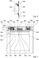
- FIG 7 shows a cooking appliance with an alternative cooking appliance control device which has a U-shaped control panel 10e and an essentially U-shaped control panel 14e.
- the control panel 10e has a total height 12e of approx. 60 mm and in the region of its transverse leg 56e a height 12e 'of approx. 30 mm.
- a display 42e is arranged above the transverse limb 56e.
- the control panel 14e has left and right next to the display 42e in two rows one above the other, control elements 22e, 24e arranged directly adjacent to one another and control elements 26e arranged as control buttons underneath the display 42e in a row next to one another.
- the operating elements 24e for setting a temperature are also designed as operating keys with symbols 36e, and a function block has, compared with the exemplary embodiments in FIG Figures 1 to 6
- Six main program operating elements forming operating elements 22e which are provided to select types of heating, namely in the present case the types of heating combined with lower heat, defrosting, convection, grill and grill combined with convection and self-cleaning.
- Control elements 20e, 26e, 28e each end with an upper and a lower outer edge 16e, 18e, 18e 'of the control panel 10e, while the control elements 22e, 24e, 26e' each end with the upper or lower outer edge 16e, 18e of the control panel Complete 10e.
- Reference number 10 Control panel 62 Recess 12 height 64 Material layer 14th Control panel 66 user interface 16 Outer edge 68 Lift button 18th Outer edge 70 Control element width 20th Control element 22nd Control element 24 Control element 26th Control element 28 Control element 30th User interface means 32 symbol 34 symbol 36 symbol 38 symbol 40 symbol 42 Display 44 Reading direction 46 Signal means 48 Home appliance door 50 Transverse leg 52 leg 54 leg 56 Transverse leg 58 Bulbs 60 Deflection angle
Description
- Die Erfindung geht aus von einem Gargerät mit einer Gargerätebedienvorrichtung nach dem Oberbegriff des Anspruchs 1.
- Es sind bereits Hausgerätebedienvorrichtungen mit einer Bedienblende und einem Bedienfeld bekannt, wobei das Bedienfeld in von der Bedienblende vollständig umschlossene Ausnehmungen der Bedienblende angeordnet ist.
- Die
DE 10 2005 049 802 A1 zeigt eine Haushaltsgerätebedienvorrichtung mit einem berührungsempfindlichen, ringförmigen Sensorfeld, das wenigstens zwei um ein Zentrum angeordnete Sensorflächen zum Detektieren eines Winkels (α) eines Berührpunkts (P) umfasst. Um eine Winkelauflösung des Sensorfelds zu verbessern, wird vorgeschlagen, dass die wenigstens zwei Sensorflächen in zumindest einem Winkelbereich in der Umfangsrichtung bezüglich des Zentrums des Sensorfelds ineinander eingreifend ausgebildet sind. - Die
DE 38 78 148 T2 offenbart ein Haushaltsgerät mit einer Anzeige- und Steuereinrichtung. - Die Aufgabe der Erfindung besteht insbesondere darin, ein Gargerät mit einer gattungsgemäßen Vorrichtung bereitzustellen, die vorteilhaft bedienbar ist. Die Aufgabe wird erfindungsgemäß durch die Merkmale des unabhängigen Patentanspruchs gelöst, während vorteilhafte Ausgestaltungen und Weiterbildungen der Erfindung den Unteransprüchen entnommen werden können.
- Die Erfindung geht aus von einem Gargerät mit einer Gargerätebedienvorrichtung, welche eine Bedienblende und ein Bedienfeld aufweist.
- Erfindungsgemäß ist vorgesehen, dass das Bedienfeld in zumindest einem Bereich zumindest im Wesentlichen mit einem oberen und/oder einem unteren Außenrand der Bedienblende abschließt. Unter einer "Bedienblende" soll dabei ein Deck- und/oder insbesondere ein Frontteil eines Hausgeräts verstanden werden, in dem ein Bedienfeld mit Bedienelementen integriert ist und das insbesondere eine oder mehrere Ausnehmungen für Bedienelemente eines Bedienfelds aufweist. Ein "Bedienelement" kann dabei von verschiedenen, dem Fachmann als sinnvoll erscheinenden Elementen gebildet sein, wie insbesondere von einem Bedienknebel oder besonders vorteilhaft von einer Bedientaste usw. Unter einem "Bedienfeld" soll insbesondere ein Feld mit zusammengehörigen Bedienelementen verstanden werden, wobei sich die Zusammengehörigkeit durch eine Bedienlogik und/oder einer räumlichen Anordnung ergeben kann. Insbesondere ist dabei ein maximaler Abstand zwischen unmittelbar benachbarten Bedienelementen kleiner als 5 cm und besonders vorteilhaft kleiner als 2 cm. Unter einem "Außenrand" soll dabei ferner ein die Bedienblende nach außen begrenzender Rand verstanden, der insbesondere seitlich neben dem Bedienfeld angeordnet ist, und es soll ein Rand einer von der Bedienblende vollständig umschlossenen Ausnehmung ausgeschlossen werden. Ferner soll unter "im Wesentlichen" in diesem Zusammenhang insbesondere verstanden werden, dass das Bedienfeld einen Abstand zu einem oberen und/oder einem unteren Außenrand von kleiner als 5% und vorteilhaft kleiner als 1 % einer Höhe des Bedienfelds in diesem Bereich und besonders vorteilhaft keinen Abstand aufweist.
- Durch eine entsprechende Ausgestaltung können die einzelnen Bedienelemente trotz einer übersichtlichen Gesamtstruktur vorteilhaft groß ausgeführt werden, und zwar insbesondere, wenn das Bedienfeld zumindest zwei übereinander bzw. in Richtung einer Höhenerstreckung nacheinander angeordnete, im Wesentlichen unmittelbar aneinander anschließende Bedienelemente aufweist. Unter "im Wesentlichen unmittelbar aneinander anschließend" soll dabei insbesondere verstanden werden, dass die Bedienelemente in Richtung der Höhenerstreckung einen Abstand kleiner als 10 mm, vorteilhaft kleiner als 5 mm und besonders vorteilhaft kleiner als 2 mm aufweisen.
- In einer weiteren Ausgestaltung der Erfindung wird vorgeschlagen, dass die Bedienblende in zumindest einem Bereich eine Höhe kleiner als 100 mm und vorteilhaft kleiner als 80 mm aufweist und besonders vorteilhaft eine Höhe zwischen 70 mm und 50 mm aufweist. Unter einer "Höhe" soll in diesem Zusammenhang insbesondere eine von der Bedienblende gebildete Frontflächenhöhe verstanden werden, die insbesondere in vertikaler Richtung verläuft.
- Durch eine entsprechende Ausgestaltung kann eine besonders übersichtliche und damit besonders vorteilhaft bedienbare Hausgerätebedienvorrichtung erreicht werden.
- Ferner wird vorgeschlagen, dass die Hausgerätebedienvorrichtung ein einstückiges Bedienoberflächenmittel aufweist, das zumindest einen Teil einer Bedienoberfläche eines ersten Bedienelements und eines zweiten Bedienelements bildet. Durch eine entsprechende Ausgestaltung kann vorteilhaft eine zumindest im Wesentlichen fugenlose Struktur erzielt und in einem passiven Zustand kann vorteilhaft erreicht werden, dass auf den Bedienelementen aufgebrachte Symbole besonders vorteilhaft erkannt und ein störendes Bedienelementenprofil bzw. Tastenprofil vermieden wird.
- Das Bedienoberflächenmittel kann dabei von verschiedenen, dem Fachmann als sinnvoll erscheinenden Mitteln gebildet sein, jedoch besonders vorteilhaft von einer Bedienfolie, die einfach, kostengünstig und robust ausgeführt werden kann.
- In einer weiteren Ausgestaltung der Erfindung wird vorgeschlagen, dass die Hausgerätebedienvorrichtung wenigstens ein in dem Bedienfeld angeordnetes Bedienelement mit einem Symbol aufweist, dessen Breite sich zumindest über 80% einer Bedienelementenbreite des Bedienelements und/oder dessen Höhe sich zumindest über 80% einer Bedienelementenhöhe des Bedienelements erstreckt, wodurch die Übersichtlichkeit weiter verbessert und die Bedienung weiter vereinfacht werden kann, und zwar insbesondere, wenn zumindest ein Großteil der Bedienelemente entsprechende Symbole aufweist.
- Weist die Hausgerätebedienvorrichtung ein oberhalb des Bedienfelds angeordnetes Display auf, kann eine Bedienung vorteilhaft durch das Display unterstützt und ein Verdecken des Displays durch einen Bediener selbst bei einer Bedienung kann vermieden werden. Das Display kann dabei eine Länge aufweisen, die kleiner oder gleich einer Länge des Bedienfelds ist oder besonders vorteilhaft, die länger als eine Länge des Bedienfelds ist.
- Ferner wird vorgeschlagen, dass das Bedienfeld zumindest zwei, vorzugsweise zumindest drei und besonders bevorzugt zumindest vier in einer Leserichtung hintereinander angeordnete Bedienelemente aufweist, die entsprechend ihrer Anordnung in Leserichtung bei wenigstens einer Bedienlogik nacheinander zu betätigen sind. Unter einer "Leserichtung" soll dabei in einer grundlegenden Bedienstellung betrachtet, wie insbesondere in einer Stellung mit einer Blickrichtung im Wesentlichen senkrecht auf eine Frontseite von vorne, von links nach rechts, verstanden werden. Ferner soll unter einer "Bedienlogik" insbesondere eine sinnvolle und insbesondere empfohlene Abfolge einer Betätigung von Bedienelementen verstanden werden. Durch eine entsprechende Anordnung kann eine vorteilhaft selbsterklärende Bedienung erreicht werden. Dabei wird vorzugsweise ein Ende des Bedienfelds von einem Hauptschalter gebildet, und zwar vorzugsweise ein in einer grundlegenden Bedienstellung betrachtet linkes Ende. Unter einem "Hauptschalter" soll dabei insbesondere ein Schalter zum Ein- und/oder Ausschalten verstanden werden.
- Ferner kann die Bedienung vereinfacht werden, wenn die Hausgerätebedienvorrichtung wenigstens ein Signalmittel aufweist, das zu einer Quittierung einer Betätigung eines Bedienelements vorgesehen ist, und zwar besonders vorzugsweise, wenn das Signalmittel in einem Flächenbereich eines ihm zugeordneten Bedienelements angeordnet ist.
- Weist das Signalmittel eine schlitzförmige Ausgestaltung auf und/oder bildet das Signalmittel zumindest einen Teil eines Rahmens eines Bedienelements, kann dieses besonders vorteilhaft Platz sparend und gut sichtbar positioniert werden. Unter einer "schlitzförmigen Ausgestaltung" soll in diesem Zusammenhang insbesondere verstanden werden, dass das Signalmittel eine mindestens dreimal und vorzugsweise mindestens fünfmal größere Länge als Breite aufweist. Unter einem "Rahmen" soll in diesem Zusammenhang insbesondere verstanden werden, dass das Signalmittel das Bedienelement seitlich begrenzt, und zwar besonders vorzugsweise über mindestens 30% seines projizierten Umfangs. Bildet das Signalmittel eine Führung eines Bedienelements, können zusätzliche Bauteile, Bauraum, Montageaufwand und Kosten eingespart werden.
- In einer weiteren Ausgestaltung wird vorgeschlagen, dass das Signalmittel zumindest teilweise einstückig mit einem Sensormittel ausgebildet ist, wodurch ferner zusätzliche Bauteile, Bauraum, Montageaufwand und Kosten eingespart werden können.
- Ferner können zusätzliche Bauteile, Montageaufwand und Kosten eingespart und ein übersichtliches Design erreicht werden, wenn die Bedienblende zumindest einen Teil eines Seitenrahmens einer Hausgerätetür bildet. Dabei soll unter einem "Seitenrahmen" insbesondere ein Rahmen verstanden werden, der die Hausgerätetür in einer horizontalen Richtung betrachtet parallel zu einer Frontseite seitlich begrenzt.
- Weist die Hausgerätebedienvorrichtung maximal sechs und vorzugsweise maximal vier Hauptprogrammbedienelemente auf, kann die Übersichtlichkeit weiter gesteigert und die Bedienung weiter vereinfacht werden. Dabei sollen unter "Hauptprogrammbedienelementen" bei Gargerätebedienvorrichtungen insbesondere Heizartenbedienelemente zum Auswählen verschiedener Heizelemente verstanden werden, wie Oberhitze, Unterhitze, Umluft, Grill und Kombinationen davon.
- Weitere Vorteile ergeben sich aus der folgenden Zeichnungsbeschreibung. In der Zeichnung sind Ausführungsbeispiele der Erfindung dargestellt. Die Zeichnung, die Beschreibung und die Ansprüche enthalten zahlreiche Merkmale in Kombination. Der Fachmann wird die Merkmale zweckmäßigerweise auch einzeln betrachten und zu sinnvollen weiteren Kombinationen zusammenfassen.
- Es zeigen:
- Fig. 1
- eine Frontansicht eines schematisch dargestellten Gargeräts mit einer Gargerätebedienvorrichtung, die eine H-förmige Bedienblende aufweist,
- Fig. 2
- eine alternative Gargerätebedienvorrichtung mit einer U-förmigen Bedienblende,
- Fig. 3
- einen schematisch dargestellten Schnitt entlang der Linie III-III in Figur 2,
- Fig. 4
- eine alternative Gargerätebedienvorrichtung mit einer leistenförmigen Bedienblende,
- Fig. 5
- eine alternative Gargerätebedienvorrichtung mit rahmenförmigen Signalmitteln,
- Fig. 6
- einen schematisch dargestellten Schnitt entlang der Linie VI-VI in Figur 6 und
- Fig. 7
- eine Frontansicht eines alternativen Gargeräts mit einer Gargerätebedienvorrichtung, die ein U-förmiges Bedienfeld aufweist.
-
Fig. 1 zeigt eine Frontansicht eines schematisch dargestellten Gargeräts mit einer Gargerätebedienvorrichtung. Die Gargerätebedienvorrichtung umfasst eine H-förmige Bedienblende 10a aus Edelstahl mit einem Querschenkel 50a mit einem darin integrierten Bedienfeld 14a und zwei vertikal verlaufenden Schenkeln 52a, 54a, die einen Seitenrahmen einer Hausgerätetür 48a des Gargeräts bilden bzw. die Hausgerätetür 48a seitlich begrenzen. Der Querschenkel 50a der Bedienblende 10a weist eine Höhe 12a von ca. 60 mm auf. Das Bedienfeld 14a weist die gleiche Höhe auf wie der Querschenkel 50a und schließt über seine gesamte Länge mit einem unteren Außenrand 16a und einem oberen Außenrand 18a des Querschenkels 50a ab, wodurch Bedienelemente 20a - 28a besonders groß und von einem Bediener leicht optisch und taktil erfassbar ausgeführt werden können. - Das Bedienfeld 14a weist die in horizontaler Richtung in einer Leserichtung 44a von links nach rechts hintereinander angeordneten Bedienelemente 20a - 28a auf, die entsprechend der Anordnung von links nach rechts bei einer empfohlenen Bedienlogik nacheinander zu betätigen sind. Ein linkes Ende des Bedienfelds 14a wird von dem als Bedientaste ausgebildeten Bedienelement 20a gebildet, das sich über die gesamte Höhe 12a der Bedienblende 10a erstreckt und einen Hauptschalter zum Ein- und Ausschalten des Gargeräts bildet. An das Bedienelement 20a schließt sich in Leserichtung 44a unmittelbar ein Funktionsblock mit den als Bedientasten ausgebildeten vier Bedienelementen 22a an, die in zwei Reihen übereinander unmittelbar aneinander anschließend und die in zwei Reihen nebeneinander unmittelbar aneinander anschließend angeordnet sind. Die Bedienelemente 22a des Funktionsblocks bilden Hauptprogrammbedienelemente, die dazu vorgesehen sind, verschiedene Heizarten auszuwählen, und zwar im vorliegenden Fall die Heizart Unterhitze mit Oberhitze kombiniert, Umluft, Grill und Grill mit Umluft kombiniert.
- In Leserichtung 44a schließt sich an den Funktionsblock das von einem Drehknebel gebildete Bedienelement 24a an, das insbesondere zu einer Einstellung einer Temperatur vorgesehen ist. An das Bedienelement 24a schließt sich in Leserichtung 44a ein Bedienblock mit den als Bedientasten ausgebildeten vier Bedienelementen 26a an, mittels derer eine Weckzeit bzw. eine Zeit bis zu einem Alarm, eine Uhrzeit, eine Backofen-Dauer und eine Endzeit eingestellt werden kann. Die Bedienelemente 26a sind entsprechend den Bedienelementen 22a in zwei Reihen nebeneinander und in zwei Reihen übereinander unmittelbar aneinander anschließend angeordnet.
- An den Bedienblock mit den Bedienelementen 26a schließt sich in Leserichtung 44a das Bedienelement 28a an, das dazu vorgesehen ist, einen ausgewählten Vorgang zu starten und das sich entsprechend dem Bedienelement 20a über die gesamte Höhe 12a der Bedienblende 10a erstreckt. Das Bedienelement 28a bildet das rechte Ende des Bedienfelds 14a.
- Bei der empfohlenen Bedienlogik wird zuerst das Gargerät am Bedienelement 20a eingeschaltet, anschließend wird über die Bedienelemente 22a des Funktionsblocks eine entsprechende Heizart ausgewählt. Darauf folgend wird an dem Bedienelement 24a eine entsprechende Temperatur eingestellt, mittels der Bedienelemente 26a des Bedienblocks wird eine Backzeit eingestellt und mittels des Bedienelements 28a wird anschließend der ausgewählte Vorgang gestartet.
- Oberhalb des Bedienfelds 14a bzw. oberhalb des Querschenkels 50a ist ein leistenförmiges Display 42a angeordnet, das die gleiche Länge aufweist wie der Querschenkel 50a und sich seitlich aufgrund seiner größeren Länge gegenüber dem Bedienfeld 14a über das Bedienfeld 14a hinaus erstreckt. Das Display 42a ist insbesondere dazu vorgesehen, ausgewählte Heizarten mittels eines Textes und mittels eines Symbols anzuzeigen.
- Die Gargerätebedienvorrichtung umfasst Signalmittel 46a, die zu einer Quittierung einer Betätigung der Bedienelemente 20a, 22a, 26a, 28a vorgesehen sind (
Figur 2 ). Jedes Signalmittel 46a ist in einem Flächenbereich eines ihm zugeordneten Bedienelements 20a - 28a angeordnet. Die Signalmittel 46a sind schlitzförmig und einstückig mit Sensormitteln ausgebildet, indem diese dazu vorgesehen sind, eine Sensorstrahlung zu übertragen, und zwar indem diese für von Infrarotstrahlung gebildete Sensorstrahlen durchlässig ausgebildet sind. Bei den betätigten Bedienelementen 20a, 22a, 26a, 28a wird sichtbares Licht über die Signalmittel 46a nach außen abgestrahlt. - Die Bedienelemente 20a, 22a, 26a, 28a weisen jeweils Symbole 32a, 34a, 38a, 40a auf, die sich jeweils über ca. 90% einer Bedienelementenbreite 70a erstrecken. Bei dem Bedienelement 20a ist das Signalmittel 46a innerhalb des Symbols 32a angeordnet, während bei den Bedienelementen 22a, 26a, 28a die Signalmittel 46a jeweils im Flächenbereich der Bedienelemente 22a, 26a, 28a, unmittelbar unterhalb der Symbole 34a, 38a, 40a angeordnet sind.
- In den
Figuren 2 bis 7 sind alternative Ausführungsbeispiele dargestellt. Im Wesentlichen gleich bleibende Bauteile, Merkmale und Funktionen sind grundsätzlich mit den gleichen Bezugszeichen beziffert. Zur Unterscheidung der Ausführungsbeispiele sind jedoch den Bezugszeichen der Ausführungsbeispiele die Buchstaben a bis e hinzugefügt. Die nachfolgende Beschreibung beschränkt sich im Wesentlichen auf die Unterschiede zu dem Ausführungsbeispiel inFigur 1 , wobei bezüglich gleich bleibender Bauteile, Merkmale und Funktionen auf die Beschreibung des Ausführungsbeispiels inFigur 1 verwiesen werden kann. - In
Figur 2 ist eine alternative Gargerätebedienvorrichtung mit einer U-förmigen Bedienblende 10b dargestellt. In einem unteren Querschenkel 56b der Bedienblende 10b ist ein Bedienfeld 14b integriert, das dieselbe Länge aufweist wie der Querschenkel 56b. Der Querschenkel 56b der Bedienblende 10b weist ca. eine Höhe 12b von 60 mm auf. Oberhalb des Bedienfelds 14b ist ein Display 42b angeordnet, das die gleiche Länge aufweist wie der Querschenkel 56b bzw. wie das Bedienfeld 14b. - Das Bedienfeld 14b weist ein einstückiges Bedienoberflächenmittel 30b auf, das bis auf ein von einem Drehknebel gebildetes Bedienelement 24b für sämtliche Bedienelemente 20b, 22b, 26b, 28b eine Bedienoberfläche 66b bildet, auf der Symbole 32b, 34b, 38b, 40b angeordnet sind. Das Bedienoberflächenmittel 30b wird von einer Bedienfolie gebildet (
Figur 3 ). Eine Bedienelementenbreite 70b wird dabei von einer jeweiligen Symbolbreite und eine Bedienelementenhöhe von einer jeweiligen Symbolhöhe selbst gebildet. - Das Bedienoberflächenmittel 30b weist für sichtbares Licht und für einen Sensorstrahl, und zwar für Infrarotstrahlen, transparente, schlitzförmige Teilbereiche auf, die Signalmittel 46b zur Quittierung einer Betätigung der Bedienelemente 20b, 22b, 26b, 28b bilden, in Flächenbereichen der jeweiligen Bedienelemente 20b, 22b, 26b, 28b angeordnet sind und einstückig mit Sensormitteln der Gargerätebedienvorrichtung ausgebildet sind. Das Bedienoberflächenmittel könnte alternativ und/oder zusätzlich von einem berührempfindlichen Mittel gebildet sein und/oder auch von einer Bedienblende selbst.
- Die Bedienelemente 20b, 22b und die Bedienelemente 26b, 28b schließen unmittelbar, fugenlos aneinander an, wodurch eine vorteilhafte Übersichtlichkeit und eine vorteilhafte Reinigungsmöglichkeit erreicht werden.
- In
Figur 4 ist eine alternative Gargerätebedienvorrichtung mit einer leistenförmigen Bedienblende 10c dargestellt. Ein oberhalb der Bedienblende 10c angeordnetes Display 42c weist dieselbe Länge auf wie die Bedienblende 10c. - In
Figur 5 ist eine alternative Gargerätebedienvorrichtung mit einer leistenförmigen Bedienblende 10d und einem Display 42d dargestellt, die bis auf speziell ausgebildete Signalmittel 46d im Wesentlichen der Gargerätebedienvorrichtung ausFigur 4 entspricht. Die zu einer Quittierung einer Betätigung von Bedienelementen 20d, 22d, 26d, 28d vorgesehenen Signalmittel 46d bilden jeweils einen Rahmen und eine Führung für die Bedienelemente 20d, 22d, 26d, 28d der Gargerätebedienvorrichtung (Figur 6 ). Die Signalmittel 46b erstrecken sich seitlich unter die Bedienblende 10d und weisen im vorliegenden Ausführungsbeispiel im Besonderen ein L-förmiges Rahmenprofil auf. Seitlich neben Ausnehmungen 62d in der Bedienblende 10d für die Bedienelemente 20d, 22d, 26d, 28d und die Signalmittel 46d sind Leuchtmittel 58d, und zwar Leuchtdioden, angeordnet. Die Signalmittel 46d sind als Lichtleiter ausgebildet, so dass von den Leuchtmitteln 58d abgestrahltes Licht innerhalb der Signalmittel 46d um einen Umlenkwinkel 60d weitergeleitet werden kann, und zwar im vorliegenden Fall um einen Umlenkwinkel von 90°. - Die Bedienelemente 20d, 22d, 26d, 28d umfassen Hubtasten 68d, die an ihrer Frontseite dasselbe Material aufweisen wie die Bedienblende 10d, und zwar sind die Hubtasten 68d an ihrer Frontseite mit einer Materialschicht 64d versehen. Im vorliegenden Ausführungsbeispiel sind die Materialschicht 64d und die Bedienblende 10d aus Edelstahl.
- In
Figur 7 ist ein Gargerät mit einer alternativen Gargerätebedienvorrichtung dargestellt, die eine U-förmige Bedienblende 10e und ein im Wesentliches U-förmiges Bedienfeld 14e aufweist. Die Bedienblende 10e weist eine Gesamthöhe 12e von ca. 60 mm und im Bereich ihres Querschenkels 56e eine Höhe 12e' von ca. 30 mm auf. Oberhalb des Querschenkels 56e ist ein Display 42e angeordnet. - Das Bedienfeld 14e weist jeweils links und rechts neben dem Display 42e in zwei Reihen übereinander, unmittelbar aneinander anschließend angeordnete Bedienelemente 22e, 24e und unter dem Display 42e in einer Reihe nebeneinander angeordnete als Bedientasten ausgebildete Bedienelemente 26e auf. Dabei sind auch die Bedienelemente 24e zum Einstellen einer Temperatur als Bedientasten mit Symbolen 36e ausgebildet, und ein Funktionsblock weist gegenüber den Ausführungsbeispielen in den
Figuren 1 bis 6 sechs Hauptprogrammbedienelemente bildende Bedienelemente 22e auf, die dazu vorgesehen sind, Heizarten auszuwählen, und zwar im vorliegenden Fall die Heizarten Unterhitze mit Oberhitze kombiniert, Auftauen, Umluft, Grill und Grill mit Umluft kombiniert und Selbstreinigung. - Die Bedienelemente 20e, 26e, 28e schließen jeweils mit einem oberen und mit einem unteren Außenrand 16e, 18e, 18e' der Bedienblende 10e ab, während die Bedienelemente 22e, 24e, 26e' jeweils mit dem oberen oder dem unteren Außenrand 16e, 18e der Bedienblende 10e abschließen.
Bezugszeichen 10 Bedienblende 62 Ausnehmung 12 Höhe 64 Materialschicht 14 Bedienfeld 66 Bedienoberfläche 16 Außenrand 68 Hubtaste 18 Außenrand 70 Bedienelementenbreite 20 Bedienelement 22 Bedienelement 24 Bedienelement 26 Bedienelement 28 Bedienelement 30 Bedienoberflächenmittel 32 Symbol 34 Symbol 36 Symbol 38 Symbol 40 Symbol 42 Display 44 Leserichtung 46 Signalmittel 48 Hausgerätetür 50 Querschenkel 52 Schenkel 54 Schenkel 56 Querschenkel 58 Leuchtmittel 60 Umlenkwinkel
Claims (21)
- Gargerät mit einer Gargerätebedienvorrichtung, welche eine Bedienblende (10a - 10e) und ein Bedienfeld (14a - 14e) aufweist, wobei das Bedienfeld (14a - 14e) ein Feld mit zusammengehörigen Bedienelementen (20a - 20e, 22a - 22e, 24a - 24e, 26a - 26e, 28a - 28e) ist,
dadurch gekennzeichnet, dass
das Bedienfeld (14a - 14e) in zumindest einem Bereich zumindest im Wesentlichen mit einem oberen und mit einem unteren Außenrand (16a - 16e, 18a - 18e) der Bedienblende (10a - 10e) abschließt. - Gargerät nach Anspruch 1,
dadurch gekennzeichnet, dass
das Bedienfeld (14a - 14e) in zumindest einem Bereich keinen Abstand zu einem oberen und einem unteren Außenrand (16a - 16e, 18a - 18e) der Bedienblende (10a - 10e) aufweist. - Gargerät nach Anspruch 1 oder 2,
dadurch gekennzeichnet, dass
das Bedienfeld (14a - 14e) zumindest zwei übereinander angeordnete im Wesentlichen unmittelbar aneinander anschließende Bedienelemente (22a - 22e, 24e, 26a - 26e) aufweist. - Gargerät nach einem der vorhergehenden Ansprüche,
dadurch gekennzeichnet, dass
die Bedienblende (10a - 10e) in zumindest einem Bereich eine Höhe (12a - 12e) kleiner als 100 mm aufweist. - Gargerät nach Anspruch 4,
dadurch gekennzeichnet, dass
die Bedienblende (10a - 10e) in dem Bereich eine Höhe (12a - 12e) kleiner als 80 mm aufweist. - Gargerät nach Anspruch 5,
dadurch gekennzeichnet, dass
die Bedienblende (10a - 10e) in dem Bereich eine Höhe (12a - 12e) zwischen 70 mm und 50 mm aufweist. - Gargerät nach einem der vorhergehenden Ansprüche,
dadurch gekennzeichnet, dass
die Gargerätebedienvorrichtung ein einstückiges Bedienoberflächenmittel (30b) aufweist, das zumindest einen Teil einer Bedienoberfläche (66b) eines ersten Bedienelements (20b, 22b, 26b, 28b) und eines zweiten Bedienelements (20b, 22b, 26b, 28b) bildet. - Gargerät nach Anspruch 7,
dadurch gekennzeichnet, dass
das Bedienoberflächenmittel (30b) von einer Bedienfolie gebildet ist. - Gargerät nach einem der vorhergehenden Ansprüche,
dadurch gekennzeichnet, dass
die Gargerätebedienvorrichtung wenigstens ein in dem Bedienfeld (14a - 14e) angeordnetes Bedienelement (20a - 20e, 22a - 22e, 24e, 26a - 26e, 28a - 28e) mit einem Symbol (32a - 32e, 34a -34e, 36e, 38a - 38e, 40a - 40e) aufweist, dessen Breite sich zumindest über 80% einer Bedienelementenbreite (70a - 70e) des Bedienelements (20a - 20e, 22a - 22e, 24e, 26a - 26e, 28a - 28e) und/oder dessen Höhe sich zumindest über 80% einer Bedienelementenhöhe erstreckt. - Gargerät nach einem der vorhergehenden Ansprüche,
dadurch gekennzeichnet, dass
die Gargerätebedienvorrichtung ein oberhalb des Bedienfelds (14a - 14e) angeordnetes Display (42a - 42e) aufweist. - Gargerät nach einem der vorhergehenden Ansprüche,
dadurch gekennzeichnet, dass
das Bedienfeld (14a - 14e) zumindest zwei in einer Leserichtung (44a - 44e) hintereinander angeordnete Bedienelemente (20a - 20e, 22a - 22e, 24a - 24e, 26a - 26e, 28a - 28e) aufweist, die entsprechend ihrer Anordnung in Leserichtung (44a - 44e) bei wenigstens einer Bedienlogik nacheinander zu betätigen sind. - Gargerät nach Anspruch 11,
dadurch gekennzeichnet, dass
ein Ende des Bedienfelds (14a - 14e) von einem Hauptschalter gebildet ist. - Gargerät nach einem der vorhergehenden Ansprüche,
dadurch gekennzeichnet, dass
die Gargerätebedienvorrichtung wenigstens ein Signalmittel (46a - 46e) aufweist, das zu einer Quittierung einer Betätigung eines Bedienelements (20a - 20e, 22a - 22e, 24e, 26a - 26e, 28a - 28e) vorgesehen ist. - Gargerät nach Anspruch 13,
dadurch gekennzeichnet, dass
das Signalmittel (46a, 46b, 46c, 46e) in einem Flächenbereich eines ihm zugeordneten Bedienelements (20a, 22a, 26a, 28a, 20b, 22b, 26b, 28b, 20c, 22c, 26c, 20e, 22e, 26e) angeordnet ist. - Gargerät nach Anspruch 13 oder 14,
dadurch gekennzeichnet, dass
das Signalmittel (46a, 46b, 46c, 46e) eine schlitzförmige Ausgestaltung aufweist. - Gargerät nach einem der Ansprüche 13 bis 15,
dadurch gekennzeichnet, dass
das Signalmittel (46d) zumindest einen Teil eines Rahmens eines Bedienelements (20d, 22d, 26d, 28d) bildet. - Gargerät nach Anspruch 16,
dadurch gekennzeichnet, dass
das Signalmittel (46d) eine Führung eines Bedienelements (20d, 22d, 26d, 28d) bildet. - Gargerät nach einem der Ansprüche 13 bis 17,
dadurch gekennzeichnet, dass
das Signalmittel (46a, 46b, 46c, 46e) zumindest teilweise einstückig mit einem Sensormittel ausgebildet ist. - Gargerät nach einem der vorhergehenden Ansprüche,
dadurch gekennzeichnet, dass
die Bedienblende (10a) zumindest einen Teil eines Seitenrahmens einer Hausgerätetür (48a) bildet. - Gargerätg nach einem der vorhergehenden Ansprüche,
dadurch gekennzeichnet, dass
die Bedienblende (10a) H-förmig ausgebildet ist. - Gargerät nach einem der vorhergehenden Ansprüche,
dadurch gekennzeichnet, dass
die Gargerätebedienvorrichtung maximal sechs verschiedene Hauptprogrammbedienelemente aufweist.
Priority Applications (1)
| Application Number | Priority Date | Filing Date | Title |
|---|---|---|---|
| PL08104516T PL2014990T3 (pl) | 2007-07-09 | 2008-06-24 | Urządzenie do obróbki termicznej z urządzeniem obsługowym urządzenia do obróbki termicznej |
Applications Claiming Priority (1)
| Application Number | Priority Date | Filing Date | Title |
|---|---|---|---|
| DE102007031885A DE102007031885A1 (de) | 2007-07-09 | 2007-07-09 | Hausgerätebedienvorrichtung |
Publications (2)
| Publication Number | Publication Date |
|---|---|
| EP2014990A1 EP2014990A1 (de) | 2009-01-14 |
| EP2014990B1 true EP2014990B1 (de) | 2020-08-26 |
Family
ID=39917660
Family Applications (1)
| Application Number | Title | Priority Date | Filing Date |
|---|---|---|---|
| EP08104516.3A Active EP2014990B1 (de) | 2007-07-09 | 2008-06-24 | Gargerät mit einer gargerätebedienvorrichtung |
Country Status (4)
| Country | Link |
|---|---|
| EP (1) | EP2014990B1 (de) |
| DE (1) | DE102007031885A1 (de) |
| ES (1) | ES2814248T3 (de) |
| PL (1) | PL2014990T3 (de) |
Cited By (1)
| Publication number | Priority date | Publication date | Assignee | Title |
|---|---|---|---|---|
| DE102021000885A1 (de) | 2021-02-19 | 2022-08-25 | Senay Buruk | Backofen/Herd in Kombination mit KühlfunktionBack-Kühl-KombiKühl-Back-Kombi |
Families Citing this family (2)
| Publication number | Priority date | Publication date | Assignee | Title |
|---|---|---|---|---|
| DE102009001980A1 (de) * | 2009-03-30 | 2010-10-07 | BSH Bosch und Siemens Hausgeräte GmbH | Bedieneinrichtung für ein Hausgerät und Verfahren zum Betreiben eines Hausgeräts mit einer Bedieneinrichtung |
| DE102014212396B4 (de) | 2014-06-27 | 2022-09-29 | BSH Hausgeräte GmbH | Haushaltsgerät mit einer perforierten Gerätekomponente |
Citations (3)
| Publication number | Priority date | Publication date | Assignee | Title |
|---|---|---|---|---|
| DE3878148T2 (de) * | 1987-10-30 | 1993-05-27 | Europ Equip Menager | Haushaltskochgeraet. |
| DE29722024U1 (de) * | 1997-12-13 | 1998-04-02 | Reimold Guenther | Schaltbare Glastüren von Haushaltsgeräten, wie Backofen, Mikrowelle, Kühlschrank und Waschmaschine |
| EP1526337A1 (de) * | 2003-10-24 | 2005-04-27 | BSH Bosch und Siemens Hausgeräte GmbH | Dunstabzugsvorrichtung mit einem Schirm aus transparentem Material |
Family Cites Families (7)
| Publication number | Priority date | Publication date | Assignee | Title |
|---|---|---|---|---|
| US678784A (en) * | 1900-05-12 | 1901-07-16 | Katherine Magner | Neck-marking machine. |
| CH678784A5 (en) * | 1989-05-31 | 1991-10-31 | Electrolux Ag | Control panel for electric baking oven - has programme keyboard for accessing and selecting stored cooking programmes |
| DE9405473U1 (de) * | 1994-03-31 | 1994-05-26 | Noth Winfried | Herd |
| DE102004009177A1 (de) * | 2004-02-25 | 2005-09-15 | BSH Bosch und Siemens Hausgeräte GmbH | Bedienfeld für programmgesteuerte Haushaltgeräte |
| DE102004049691A1 (de) * | 2004-10-12 | 2006-04-13 | BSH Bosch und Siemens Hausgeräte GmbH | Bedieneinrichtung |
| DE102005049802A1 (de) * | 2005-10-18 | 2007-04-19 | BSH Bosch und Siemens Hausgeräte GmbH | Haushaltsgerätebedienvorrichtung |
| DE202007002887U1 (de) * | 2007-02-28 | 2007-04-19 | Störk-Tronic, Störk GmbH & Co KG | Bediensystem |
-
2007
- 2007-07-09 DE DE102007031885A patent/DE102007031885A1/de not_active Withdrawn
-
2008
- 2008-06-24 PL PL08104516T patent/PL2014990T3/pl unknown
- 2008-06-24 ES ES08104516T patent/ES2814248T3/es active Active
- 2008-06-24 EP EP08104516.3A patent/EP2014990B1/de active Active
Patent Citations (3)
| Publication number | Priority date | Publication date | Assignee | Title |
|---|---|---|---|---|
| DE3878148T2 (de) * | 1987-10-30 | 1993-05-27 | Europ Equip Menager | Haushaltskochgeraet. |
| DE29722024U1 (de) * | 1997-12-13 | 1998-04-02 | Reimold Guenther | Schaltbare Glastüren von Haushaltsgeräten, wie Backofen, Mikrowelle, Kühlschrank und Waschmaschine |
| EP1526337A1 (de) * | 2003-10-24 | 2005-04-27 | BSH Bosch und Siemens Hausgeräte GmbH | Dunstabzugsvorrichtung mit einem Schirm aus transparentem Material |
Cited By (1)
| Publication number | Priority date | Publication date | Assignee | Title |
|---|---|---|---|---|
| DE102021000885A1 (de) | 2021-02-19 | 2022-08-25 | Senay Buruk | Backofen/Herd in Kombination mit KühlfunktionBack-Kühl-KombiKühl-Back-Kombi |
Also Published As
| Publication number | Publication date |
|---|---|
| ES2814248T3 (es) | 2021-03-26 |
| DE102007031885A1 (de) | 2009-01-15 |
| EP2014990A1 (de) | 2009-01-14 |
| PL2014990T3 (pl) | 2021-04-06 |
Similar Documents
| Publication | Publication Date | Title |
|---|---|---|
| EP1338849B1 (de) | Verfahren zur Behandlung und Zubereitung von Nahrungsmitteln in einem Gargerät, Bedienfeld für ein Gargerät sowie Gargerät mit Bedienfeld | |
| EP1844265A1 (de) | Hausgeräteeinstelleinheit | |
| DE102007048834A1 (de) | Hausgerätevorrichtung mit wenigstens einer Kamera | |
| DE19918290C1 (de) | Kochgerät mit einfach handhabbarer Bedieneinrichtung | |
| DE102005018298A1 (de) | Verfahren zur Ansteuerung und/oder Auswertung eines länglichen Sensorelements einer Bedieneinrichtung und eine solche Bedieneinrichtung | |
| EP2014990B1 (de) | Gargerät mit einer gargerätebedienvorrichtung | |
| EP2026010B1 (de) | Haushaltsgerätebedienvorrichtung | |
| WO2017102243A1 (de) | Heizkörperanordnung für ein gargerät sowie gargerät mit einer entsprechenden heizkörperanordnung | |
| EP0797052B1 (de) | Versenkbares Bedienelement | |
| DE3229406A1 (de) | Kochmulde, insbesondere glaskeramik-kochmulde mit bedienorganen | |
| EP2276322B1 (de) | Verfahren zum Betrieb eines Kochfelds | |
| EP3330617B1 (de) | Kochfeld und verfahren zum betrieb eines solchen kochfeldes | |
| DE10211047B4 (de) | Anordnung zur Steuerung eines Kochfeldes | |
| WO2009007291A2 (de) | Hausgerätebedienvorrichtung | |
| EP3612002B1 (de) | Verfahren zur ansteuerung einer heizeinrichtung eines kochfelds und kochfeld | |
| EP0859193B1 (de) | Bedien- und Anzeigeanordnung für einen Herd, insbesondere für einen Haushaltsherd | |
| EP2702922A2 (de) | Verfahren zum Bedienen eines Haushaltsgeräts sowie Haushaltsgerät mit ergonomischer Bedienvorrichtung | |
| WO2005102139A1 (de) | Geschirrspülmaschine mit optischer betriebsablaufanzeige | |
| DE102004011749A1 (de) | Elektronisch gesteuertes Kochfeld mit mehreren Kochstellen und Verfahren zum Betrieb eines solchen Kochfeldes | |
| DE102019215458B4 (de) | Anzeigevorrichtung für ein Haushaltsgerät, Haushaltsgerät mit Anzeigevorrichtung und Herstellungsverfahren für eine Anzeigevorrichtung | |
| DE2723325C2 (de) | Sensorschalter-Einrichtung | |
| EP3330616B1 (de) | Kochfeld und verfahren zum betrieb eines solchen kochfeldes | |
| EP4199791A1 (de) | Touchdisplay für eine küchenmaschine, abschalteinrichtung und küchenmaschine | |
| EP4274382A1 (de) | Kochfeldvorrichtung | |
| DE202005008787U1 (de) | Bedieneinrichtung für ein Kochfeld und Kochfeld mit einer solchen Bedieneinrichtung |
Legal Events
| Date | Code | Title | Description |
|---|---|---|---|
| PUAI | Public reference made under article 153(3) epc to a published international application that has entered the european phase |
Free format text: ORIGINAL CODE: 0009012 |
|
| AK | Designated contracting states |
Kind code of ref document: A1 Designated state(s): AT BE BG CH CY CZ DE DK EE ES FI FR GB GR HR HU IE IS IT LI LT LU LV MC MT NL NO PL PT RO SE SI SK TR |
|
| AX | Request for extension of the european patent |
Extension state: AL BA MK RS |
|
| 17P | Request for examination filed |
Effective date: 20090714 |
|
| 17Q | First examination report despatched |
Effective date: 20090814 |
|
| AKX | Designation fees paid |
Designated state(s): AT BE BG CH CY CZ DE DK EE ES FI FR GB GR HR HU IE IS IT LI LT LU LV MC MT NL NO PL PT RO SE SI SK TR |
|
| RAP1 | Party data changed (applicant data changed or rights of an application transferred) |
Owner name: BSH HAUSGERAETE GMBH |
|
| STAA | Information on the status of an ep patent application or granted ep patent |
Free format text: STATUS: EXAMINATION IS IN PROGRESS |
|
| GRAP | Despatch of communication of intention to grant a patent |
Free format text: ORIGINAL CODE: EPIDOSNIGR1 |
|
| STAA | Information on the status of an ep patent application or granted ep patent |
Free format text: STATUS: GRANT OF PATENT IS INTENDED |
|
| INTG | Intention to grant announced |
Effective date: 20200414 |
|
| RIC1 | Information provided on ipc code assigned before grant |
Ipc: D06F 34/28 20200101ALI20200327BHEP Ipc: A47L 15/42 20060101ALI20200327BHEP Ipc: F24C 7/08 20060101AFI20200327BHEP |
|
| GRAS | Grant fee paid |
Free format text: ORIGINAL CODE: EPIDOSNIGR3 |
|
| GRAA | (expected) grant |
Free format text: ORIGINAL CODE: 0009210 |
|
| STAA | Information on the status of an ep patent application or granted ep patent |
Free format text: STATUS: THE PATENT HAS BEEN GRANTED |
|
| AK | Designated contracting states |
Kind code of ref document: B1 Designated state(s): AT BE BG CH CY CZ DE DK EE ES FI FR GB GR HR HU IE IS IT LI LT LU LV MC MT NL NO PL PT RO SE SI SK TR |
|
| REG | Reference to a national code |
Ref country code: GB Ref legal event code: FG4D Free format text: NOT ENGLISH |
|
| REG | Reference to a national code |
Ref country code: CH Ref legal event code: EP |
|
| REG | Reference to a national code |
Ref country code: DE Ref legal event code: R096 Ref document number: 502008017133 Country of ref document: DE |
|
| REG | Reference to a national code |
Ref country code: AT Ref legal event code: REF Ref document number: 1306741 Country of ref document: AT Kind code of ref document: T Effective date: 20200915 |
|
| REG | Reference to a national code |
Ref country code: IE Ref legal event code: FG4D Free format text: LANGUAGE OF EP DOCUMENT: GERMAN |
|
| REG | Reference to a national code |
Ref country code: LT Ref legal event code: MG4D |
|
| PG25 | Lapsed in a contracting state [announced via postgrant information from national office to epo] |
Ref country code: BG Free format text: LAPSE BECAUSE OF FAILURE TO SUBMIT A TRANSLATION OF THE DESCRIPTION OR TO PAY THE FEE WITHIN THE PRESCRIBED TIME-LIMIT Effective date: 20201126 Ref country code: NO Free format text: LAPSE BECAUSE OF FAILURE TO SUBMIT A TRANSLATION OF THE DESCRIPTION OR TO PAY THE FEE WITHIN THE PRESCRIBED TIME-LIMIT Effective date: 20201126 Ref country code: HR Free format text: LAPSE BECAUSE OF FAILURE TO SUBMIT A TRANSLATION OF THE DESCRIPTION OR TO PAY THE FEE WITHIN THE PRESCRIBED TIME-LIMIT Effective date: 20200826 Ref country code: GR Free format text: LAPSE BECAUSE OF FAILURE TO SUBMIT A TRANSLATION OF THE DESCRIPTION OR TO PAY THE FEE WITHIN THE PRESCRIBED TIME-LIMIT Effective date: 20201127 Ref country code: LT Free format text: LAPSE BECAUSE OF FAILURE TO SUBMIT A TRANSLATION OF THE DESCRIPTION OR TO PAY THE FEE WITHIN THE PRESCRIBED TIME-LIMIT Effective date: 20200826 Ref country code: SE Free format text: LAPSE BECAUSE OF FAILURE TO SUBMIT A TRANSLATION OF THE DESCRIPTION OR TO PAY THE FEE WITHIN THE PRESCRIBED TIME-LIMIT Effective date: 20200826 Ref country code: FI Free format text: LAPSE BECAUSE OF FAILURE TO SUBMIT A TRANSLATION OF THE DESCRIPTION OR TO PAY THE FEE WITHIN THE PRESCRIBED TIME-LIMIT Effective date: 20200826 Ref country code: PT Free format text: LAPSE BECAUSE OF FAILURE TO SUBMIT A TRANSLATION OF THE DESCRIPTION OR TO PAY THE FEE WITHIN THE PRESCRIBED TIME-LIMIT Effective date: 20201228 |
|
| REG | Reference to a national code |
Ref country code: NL Ref legal event code: MP Effective date: 20200826 |
|
| PG25 | Lapsed in a contracting state [announced via postgrant information from national office to epo] |
Ref country code: IS Free format text: LAPSE BECAUSE OF FAILURE TO SUBMIT A TRANSLATION OF THE DESCRIPTION OR TO PAY THE FEE WITHIN THE PRESCRIBED TIME-LIMIT Effective date: 20201226 Ref country code: LV Free format text: LAPSE BECAUSE OF FAILURE TO SUBMIT A TRANSLATION OF THE DESCRIPTION OR TO PAY THE FEE WITHIN THE PRESCRIBED TIME-LIMIT Effective date: 20200826 Ref country code: NL Free format text: LAPSE BECAUSE OF FAILURE TO SUBMIT A TRANSLATION OF THE DESCRIPTION OR TO PAY THE FEE WITHIN THE PRESCRIBED TIME-LIMIT Effective date: 20200826 |
|
| REG | Reference to a national code |
Ref country code: ES Ref legal event code: FG2A Ref document number: 2814248 Country of ref document: ES Kind code of ref document: T3 Effective date: 20210326 |
|
| PG25 | Lapsed in a contracting state [announced via postgrant information from national office to epo] |
Ref country code: CZ Free format text: LAPSE BECAUSE OF FAILURE TO SUBMIT A TRANSLATION OF THE DESCRIPTION OR TO PAY THE FEE WITHIN THE PRESCRIBED TIME-LIMIT Effective date: 20200826 Ref country code: EE Free format text: LAPSE BECAUSE OF FAILURE TO SUBMIT A TRANSLATION OF THE DESCRIPTION OR TO PAY THE FEE WITHIN THE PRESCRIBED TIME-LIMIT Effective date: 20200826 Ref country code: DK Free format text: LAPSE BECAUSE OF FAILURE TO SUBMIT A TRANSLATION OF THE DESCRIPTION OR TO PAY THE FEE WITHIN THE PRESCRIBED TIME-LIMIT Effective date: 20200826 Ref country code: RO Free format text: LAPSE BECAUSE OF FAILURE TO SUBMIT A TRANSLATION OF THE DESCRIPTION OR TO PAY THE FEE WITHIN THE PRESCRIBED TIME-LIMIT Effective date: 20200826 |
|
| REG | Reference to a national code |
Ref country code: DE Ref legal event code: R097 Ref document number: 502008017133 Country of ref document: DE |
|
| PG25 | Lapsed in a contracting state [announced via postgrant information from national office to epo] |
Ref country code: SK Free format text: LAPSE BECAUSE OF FAILURE TO SUBMIT A TRANSLATION OF THE DESCRIPTION OR TO PAY THE FEE WITHIN THE PRESCRIBED TIME-LIMIT Effective date: 20200826 |
|
| PLBE | No opposition filed within time limit |
Free format text: ORIGINAL CODE: 0009261 |
|
| STAA | Information on the status of an ep patent application or granted ep patent |
Free format text: STATUS: NO OPPOSITION FILED WITHIN TIME LIMIT |
|
| 26N | No opposition filed |
Effective date: 20210527 |
|
| PG25 | Lapsed in a contracting state [announced via postgrant information from national office to epo] |
Ref country code: SI Free format text: LAPSE BECAUSE OF FAILURE TO SUBMIT A TRANSLATION OF THE DESCRIPTION OR TO PAY THE FEE WITHIN THE PRESCRIBED TIME-LIMIT Effective date: 20200826 |
|
| PG25 | Lapsed in a contracting state [announced via postgrant information from national office to epo] |
Ref country code: MC Free format text: LAPSE BECAUSE OF FAILURE TO SUBMIT A TRANSLATION OF THE DESCRIPTION OR TO PAY THE FEE WITHIN THE PRESCRIBED TIME-LIMIT Effective date: 20200826 |
|
| REG | Reference to a national code |
Ref country code: CH Ref legal event code: PL |
|
| REG | Reference to a national code |
Ref country code: BE Ref legal event code: MM Effective date: 20210630 |
|
| PG25 | Lapsed in a contracting state [announced via postgrant information from national office to epo] |
Ref country code: LU Free format text: LAPSE BECAUSE OF NON-PAYMENT OF DUE FEES Effective date: 20210624 |
|
| PG25 | Lapsed in a contracting state [announced via postgrant information from national office to epo] |
Ref country code: LI Free format text: LAPSE BECAUSE OF NON-PAYMENT OF DUE FEES Effective date: 20210630 Ref country code: IE Free format text: LAPSE BECAUSE OF NON-PAYMENT OF DUE FEES Effective date: 20210624 Ref country code: CH Free format text: LAPSE BECAUSE OF NON-PAYMENT OF DUE FEES Effective date: 20210630 |
|
| PG25 | Lapsed in a contracting state [announced via postgrant information from national office to epo] |
Ref country code: BE Free format text: LAPSE BECAUSE OF NON-PAYMENT OF DUE FEES Effective date: 20210630 |
|
| REG | Reference to a national code |
Ref country code: AT Ref legal event code: MM01 Ref document number: 1306741 Country of ref document: AT Kind code of ref document: T Effective date: 20210624 |
|
| PG25 | Lapsed in a contracting state [announced via postgrant information from national office to epo] |
Ref country code: AT Free format text: LAPSE BECAUSE OF NON-PAYMENT OF DUE FEES Effective date: 20210624 |
|
| PG25 | Lapsed in a contracting state [announced via postgrant information from national office to epo] |
Ref country code: HU Free format text: LAPSE BECAUSE OF FAILURE TO SUBMIT A TRANSLATION OF THE DESCRIPTION OR TO PAY THE FEE WITHIN THE PRESCRIBED TIME-LIMIT; INVALID AB INITIO Effective date: 20080624 Ref country code: CY Free format text: LAPSE BECAUSE OF FAILURE TO SUBMIT A TRANSLATION OF THE DESCRIPTION OR TO PAY THE FEE WITHIN THE PRESCRIBED TIME-LIMIT Effective date: 20200826 |
|
| PGFP | Annual fee paid to national office [announced via postgrant information from national office to epo] |
Ref country code: FR Payment date: 20230622 Year of fee payment: 16 Ref country code: DE Payment date: 20230630 Year of fee payment: 16 |
|
| PGFP | Annual fee paid to national office [announced via postgrant information from national office to epo] |
Ref country code: TR Payment date: 20230619 Year of fee payment: 16 Ref country code: PL Payment date: 20230616 Year of fee payment: 16 |
|
| PGFP | Annual fee paid to national office [announced via postgrant information from national office to epo] |
Ref country code: IT Payment date: 20230630 Year of fee payment: 16 Ref country code: GB Payment date: 20230622 Year of fee payment: 16 Ref country code: ES Payment date: 20230719 Year of fee payment: 16 |