EP2014493A2 - Guidage latéral pour store d'occultation et store d'occultation pour véhicule automobile - Google Patents
Guidage latéral pour store d'occultation et store d'occultation pour véhicule automobile Download PDFInfo
- Publication number
- EP2014493A2 EP2014493A2 EP08011042A EP08011042A EP2014493A2 EP 2014493 A2 EP2014493 A2 EP 2014493A2 EP 08011042 A EP08011042 A EP 08011042A EP 08011042 A EP08011042 A EP 08011042A EP 2014493 A2 EP2014493 A2 EP 2014493A2
- Authority
- EP
- European Patent Office
- Prior art keywords
- roller blind
- guide rail
- plug
- connecting piece
- guide
- Prior art date
- Legal status (The legal status is an assumption and is not a legal conclusion. Google has not performed a legal analysis and makes no representation as to the accuracy of the status listed.)
- Granted
Links
Images

Classifications
-
- B—PERFORMING OPERATIONS; TRANSPORTING
- B60—VEHICLES IN GENERAL
- B60J—WINDOWS, WINDSCREENS, NON-FIXED ROOFS, DOORS, OR SIMILAR DEVICES FOR VEHICLES; REMOVABLE EXTERNAL PROTECTIVE COVERINGS SPECIALLY ADAPTED FOR VEHICLES
- B60J3/00—Antiglare equipment associated with windows or windscreens; Sun visors for vehicles
- B60J3/02—Antiglare equipment associated with windows or windscreens; Sun visors for vehicles adjustable in position
-
- E—FIXED CONSTRUCTIONS
- E06—DOORS, WINDOWS, SHUTTERS, OR ROLLER BLINDS IN GENERAL; LADDERS
- E06B—FIXED OR MOVABLE CLOSURES FOR OPENINGS IN BUILDINGS, VEHICLES, FENCES OR LIKE ENCLOSURES IN GENERAL, e.g. DOORS, WINDOWS, BLINDS, GATES
- E06B9/00—Screening or protective devices for wall or similar openings, with or without operating or securing mechanisms; Closures of similar construction
- E06B9/56—Operating, guiding or securing devices or arrangements for roll-type closures; Spring drums; Tape drums; Counterweighting arrangements therefor
- E06B9/58—Guiding devices
-
- B—PERFORMING OPERATIONS; TRANSPORTING
- B60—VEHICLES IN GENERAL
- B60J—WINDOWS, WINDSCREENS, NON-FIXED ROOFS, DOORS, OR SIMILAR DEVICES FOR VEHICLES; REMOVABLE EXTERNAL PROTECTIVE COVERINGS SPECIALLY ADAPTED FOR VEHICLES
- B60J1/00—Windows; Windscreens; Accessories therefor
- B60J1/20—Accessories, e.g. wind deflectors, blinds
- B60J1/2011—Blinds; curtains or screens reducing heat or light intensity
- B60J1/2013—Roller blinds
- B60J1/2019—Roller blinds powered, e.g. by electric, hydraulic or pneumatic actuators
- B60J1/2027—Roller blinds powered, e.g. by electric, hydraulic or pneumatic actuators with a buckle-proof guided flexible actuating element acting on the draw bar for pushing or push-pulling, e.g. a Bowden cable
-
- B—PERFORMING OPERATIONS; TRANSPORTING
- B60—VEHICLES IN GENERAL
- B60J—WINDOWS, WINDSCREENS, NON-FIXED ROOFS, DOORS, OR SIMILAR DEVICES FOR VEHICLES; REMOVABLE EXTERNAL PROTECTIVE COVERINGS SPECIALLY ADAPTED FOR VEHICLES
- B60J1/00—Windows; Windscreens; Accessories therefor
- B60J1/20—Accessories, e.g. wind deflectors, blinds
- B60J1/2011—Blinds; curtains or screens reducing heat or light intensity
- B60J1/2013—Roller blinds
- B60J1/2066—Arrangement of blinds in vehicles
- B60J1/2086—Arrangement of blinds in vehicles specially adapted for openable windows, e.g. side window
-
- B—PERFORMING OPERATIONS; TRANSPORTING
- B60—VEHICLES IN GENERAL
- B60J—WINDOWS, WINDSCREENS, NON-FIXED ROOFS, DOORS, OR SIMILAR DEVICES FOR VEHICLES; REMOVABLE EXTERNAL PROTECTIVE COVERINGS SPECIALLY ADAPTED FOR VEHICLES
- B60J3/00—Antiglare equipment associated with windows or windscreens; Sun visors for vehicles
Definitions
- the invention relates to a side guide for a shade and an associated shade for motor vehicles.
- a rear window roller blind which comprises a winding shaft, a roll-up web that can be wound thereon and an extension profile attached to the free end of the roller blind rail.
- the pull-out profile is guided on at least one end in a guide rail.
- the rear window blind further comprises a base device, which serves as a bearing device for the winding shaft.
- the guide rails can be used on an assembly line in side trim parts of the C-pillars of the motor vehicle and mounted on these.
- the guide rail is provided with a first plug-in means.
- the base device has a coupling device, which comprises a second plug-in means which is complementary to the first plug-in means and can be coupled thereto.
- the rear window blind can with the Base device, for example, be mounted below a rear shelf. Subsequently, in a separate step, the side trim parts with the guide rails inserted therein can be mounted on the C-pillars. In a further step, the plug-in means are locked together with a precise fit. The second plug-in means is mounted on a resilient style, so as to position the two plug-in means relative to each other.
- a side guide for a shading shade comprising at least one guide rail with a first plug-in means and a connecting piece with a second plug-in means which is complementary to the first plug-in means and can be coupled thereto, wherein the mutually coupled plug-in means for a tolerance compensation relative to each other are displaceable.
- the connection between the guide rail and the connecting piece - more precisely between the two plug-in means - is thus not rigid at least in an insertion direction or axial direction of the rail.
- the connector has a degree of freedom, at least in the direction of insertion.
- the plug-in direction is also referred to as the axial direction of the guide rail, wherein the guide rail can extend arcuately.
- the plug-in means in the insertion direction on at least one groove and a spring complementary thereto.
- the groove is formed in one embodiment on the guide rail, wherein the complementary spring is formed on the connecting piece.
- a spring is formed on the guide rail, which is insertable into a groove on the connecting piece.
- the plug-in means in the insertion direction complementary gears.
- complementary gears By such teeth, it is possible that in a coupling remaining gaps or a remaining gap between the connector and the guide rail do not act as so-called bumps or bumps for a slidable in the guide rail sliding element or the like.
- the width of the individual grooves and / or springs, by which the toothing is formed, is preferably smaller than the width of a sliding element guided in the guide rail.
- At least one plug-in means at least one latching element, by means of which the guide rail and the connector in the insertion direction under play are locked together.
- the plug-in means are connected to one another in the direction of insertion in a floating manner.
- the locking means forms a stop, as it limits a maximum distance of the plug-in means from each other and thereby prevents unwanted disengagement during use.
- the guide rail and the connecting piece coaxially detachable guide grooves for a sliding element.
- the sliding element is connected, for example, with a pull-out profile of a roller blind of the shade blind.
- means for displacing the sliding element can be attached to the sliding element attack in the guide grooves.
- the guide rail and / or the guide groove are preferably curved, in particular (arcuate) arc-shaped, but discontinuities in the course of the guide groove are avoided for a good displaceability of the sliding element.
- the curvature of the guide rail and / or the guide groove follows a contour of an associated window.
- the object is further achieved by a shading blind for a motor vehicle with a pull-out profile, which is guided in a side guide according to the invention.
- the shading roller blind is designed, for example, as a sun blind on a panoramic window in the vehicle roof, as a sun and / or blinds on a side door or as a rear window roller blind.
- the pull-out profile has, in one embodiment, at least one end of a sliding element or the like, which is mounted displaceably in the guide groove.
- the sliding element is designed in one embodiment in one piece with the pull-out profile. In other embodiments, the sliding element is made separately, for example, as a sliding block, wherein a connection between the pull-out profile and sliding block can be designed to be pivotable.
- the pull-out profile is arranged at a free end of a roller blind, so that the roller blind can be unwound by applying a force to the pull-out profile in a withdrawal direction of a winding shaft.
- the pull-out profile is firmly connected in one embodiment with the roller blind and / or at least partially designed in one piece with this.
- the drawer profile along one edge of the roller blind is slidably mounted on this.
- the guide rail is connected to a body and / or a trim part of a motor vehicle, in particular in the region of a C-pillar, and / or at least partially designed in one piece with this.
- the shade blind is designed for example as a rear window roller blind, wherein the guide rails are arranged on the C-pillars of the motor vehicle.
- the guide rails are already connectable in a pre-assembly with the vehicle body and / or a corresponding side trim part, for which purpose suitable latching means may be provided on each guide rail, as for example in the EP 1 533 157 A2 are described.
- the inventive connector with tolerance compensation a simple connection of attached to the side trim part guide rail with the connector in the final assembly is possible.
- the connecting piece is formed on a base device and / or connectable to a base device.
- the base device is used for pre-assembly and / or a test operation of the shade blind.
- the shading shade can be mounted with the base device in the motor vehicle, for example in the region of a side window or below a rear shelf.
- a corresponding base device is for example in the already mentioned EP 1 533 157 A2 whose contents are fully referenced.
- the base device comprises in one embodiment a resilient pin or style through which the connector is mounted. By such elastic mounting further degrees of freedom for the connector of the connector are realized with the guide rail.
- the base device preferably also serves as a holder for a winding shaft of the shade blinds.
- a drive device for unwinding a roller blind from a winding shaft and / or for winding up the roller blind on a winding shaft.
- the drive means a fully automatic and / or semi-automatic operation of the shade blinds is possible.
- a semi-automatic Actuating device is designed for example as a spring-loaded arrangement, wherein the winding shaft and / or the roller blind can be locked in a stowed position and after releasing the locking the roller blind is unwound due to a spring force.
- a retraction and winding of the roller blind is, however, by hand against the spring force of the spring-loaded arrangement, wherein a return spring, a compact winding of the blind is realized on the winding shaft.
- a unwinding can be done by a manual operation, wherein the roller blind can be hooked, for example in one or more desired, extended positions and winding takes place automatically by loosening the entanglement by the return spring or a spring motor.
- motor drives are provided, wherein the user is supported by the motor drive in the operation and / or the motor drive replaces a manual operation.
- the motor drive interacts, for example, with a so-called antenna, which acts on the pull-out profile for unwinding the roller blind.
- the motor drive can be designed for example as a pneumatic drive, hydraulic drive and / or with an electric motor.
- the drive device comprises at least one flexible thrust element, which is ausknickêtêt in the guide rail and / or the connecting piece feasible.
- the thrust element engages a sliding element or the like, which is guided in the guide groove and is operatively connected to the shading shade, in particular with an extension profile.
- the thrust element is designed for example as a so-called flex shaft, rack or toothed cord with a substantially cylindrical core and a coil surrounding the core. Such a rack is drivable in a simple manner by a gear, which in turn is driven by an electric motor or the like.
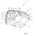
- FIG. 1 schematically shows a rear area of a motor vehicle 1 in a partially cutaway, perspective view with a view on the inside of a rear, right side door 2.
- the motor vehicle 1 has a vehicle roof 10, from the side of a B-pillar 11 of the motor vehicle 1 leads to a floor group, not shown. As is known, a corresponding B-pillar on the FIG. 1 not shown left side of the motor vehicle 1 is provided.
- the illustrated motor vehicle 1 further comprises a C-pillar 12 with a side panel 120.
- the roof 10 is at a trailing edge in a frame of a rear window opening 13, in which a rear window, not shown, can be used.
- the right, rear side door 2 is mounted in a known manner, in particular by means not shown hinges. At the height of the side door 2 is a rear seat 3.
- an interior of the motor vehicle 1 facing inside of the side door 2 has an inner lining 20.
- a door handle 21 and an actuating pawl 22 are provided for a door lock, not shown.
- Other elements, not shown, such as speakers and the like, may also be integrated into the side door 2 and / or attached thereto.
- the side door 2 has a window opening 23, which is divided into a first section 24 and a second section 25 by a web 26.
- the second section 25 is designed as an opening for a so-called triangular window, so that the window opening 23 is substantially trapezoidal.
- the window opening 23 has a lower edge 27 and an upper edge 28, wherein the upper edge 28 is usually not parallel to the lower edge 27, but may extend curved.
- a non-illustrated, two-part side window can be used.
- the side window is usually displaceable at least in the first section 24.
- the window opening 23 can be covered by a shading roller blind designed as a side window roller 4 with a roller blind 40.
- the illustrated side window roller blind 4 includes linear guide means 5 with a pullout profile 50 and an antenna or rod 51.
- the pullout 50 is attached to a free edge of the shade 40.
- the pull-out profile 50 is guided in a arranged in the B-pillar 11, not visible lateral guide rail.
- the pull-out profile 50 is movable by means of the rod 51.
- the linear guide means 5 includes thrust members or the like, which are guided in the non-visible guide rail. In still other embodiments unwinding of the roller blind 40 is done manually.
- a rear window shade 6 shading roller blind with a roller blind 60 for covering the rear window opening 13 is provided.
- a pull-out profile 70 is arranged, which is guided in two lateral guide rails 14, of which in Fig. 1 only one is visible.
- the guide rails 14 are arranged in the region of the C-pillars 12 and connected to the vehicle body and / or the side panel.
- the roller blind 60 is on an in Fig. 1 Winding shaft, not shown, can be wound up, which is arranged below a rear shelf 15, wherein the roller blind 60 is guided through a slot 16.
- Fig. 2 schematically shows the rear region of the motor vehicle 1 according to Fig. 1 with a view from the rear of the interior, in particular the rear window blind 6 is visible. Details III and IV are enlarged in the Fig. 3 and 4 shown.
- the illustrated rear window roller 6 comprises a winding shaft 61, on which the roller blind 60 can be wound up.
- the winding shaft 61 is in a schematically illustrated base device 8 stored.
- the pull-out profile 70 is arranged.
- the pull-out profile 70 has at both ends sliding elements 71, wherein one of the sliding elements 71 in detail in Fig. 3 is recognizable.
- the sliding element 71 is pivotally connected to the pull-out profile 70.
- the guide rail 14 has a guide groove 140, in which the sliding element 71 is displaceably guided.
- the guide groove 140 may have any shape for this purpose.
- a motor drive 72 for automatic and / or remote open and / or unwinding of the roller blind 60 of the winding shaft 61 is provided.
- the motor drive 72 cooperates in the illustrated embodiment with a shear member 73 shown schematically, which as in Fig. 3 represented on the sliding element 71 for unwinding the roller blind 60 attacks.
- the thrust member 73 is designed for example as a so-called toothed cord, which is driven by a not shown, provided on the drive 72 gear.
- the thrust member 73 is also displaceable in the guide groove 140, wherein the thrust member 73 is preferably performed in the guide groove 140 ausknickêtêt.
- the push member itself can be made kink-resistant, so that a kink-proof leadership is not necessary.
- the guide rail 14 is integrated in the illustrated embodiment in the side panel 120 of the C-pillar 12 and mounted with this in the motor vehicle 1.
- the rear window roller blind 6 can be mounted below the rear shelf 15.
- a connecting piece 80 is provided, wherein the guide rail 14 and the connecting piece 80 are mutually coupled by mutually complementary plug-in means.
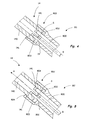
- Fig. 4 shows in detail the connection of the plug-in means of the guide rail 14 with the plug-in means connection piece 80 in a sectional view.
- the connecting piece 80 has a guide groove 800, which is designed coaxially with the guide groove 140 of the guide rail 14.
- the connecting piece 80 is widened at one end 801, so that the guide rail 14 can be inserted into the end 801.
- springs 802 are further formed, which engage in complementary grooves 141 of the guide rail 14.
- a width B of a gap s remaining during coupling between the guide rail 14 and the connecting piece 80 is thereby also reduced, so that bumping points for a sliding element 71 according to FIGS Fig. 3 are avoidable.
- a maximum insertion depth of the guide rail 14 into the connecting piece 80 is limited by a stop 803 on the connecting piece 80 and the depth of the grooves 141.
- Fig. 5 shows a guide rail 14 'and a connector 80' according to a second embodiment of the invention.
- the components essentially correspond to the components according to Fig. 4 , Uniform reference symbols are used for the same components and a detailed description of these components will be omitted.
- At one end 801 'of the connecting piece 80' for receiving the guide rail 14 'locking lugs 804 are formed, by which a movement of the guide rail 14' relative to the connecting piece 80 'in the axial direction A is limited against the insertion direction.
- the connecting piece 80 'and the guide rail 14' with play in the axial direction A are locked together. As a result, an unwanted release of the connector between the connector 80 'and the guide rail 14' is prevented.
- the connecting pieces 80, 80 ' may, for example, from the EP 1 533 157 A2 be known to be mounted on a spring-elastic pin, so that in the base device 8 according to EP 1 533 157 A2 realized degrees of freedom are maintained.
- a tolerance compensation in the axial direction A is created according to the invention.
Applications Claiming Priority (1)
| Application Number | Priority Date | Filing Date | Title |
|---|---|---|---|
| DE102007034693A DE102007034693A1 (de) | 2007-07-11 | 2007-07-11 | Seitenführung für Beschattungsrollo und Beschattungsrollo für Kraftfahrzeuge |
Publications (3)
| Publication Number | Publication Date |
|---|---|
| EP2014493A2 true EP2014493A2 (fr) | 2009-01-14 |
| EP2014493A3 EP2014493A3 (fr) | 2010-12-22 |
| EP2014493B1 EP2014493B1 (fr) | 2011-12-14 |
Family
ID=39047415
Family Applications (1)
| Application Number | Title | Priority Date | Filing Date |
|---|---|---|---|
| EP08011042A Active EP2014493B1 (fr) | 2007-07-11 | 2008-06-18 | Guidage latéral pour store d'occultation et store d'occultation pour véhicule automobile |
Country Status (6)
| Country | Link |
|---|---|
| US (1) | US8800635B2 (fr) |
| EP (1) | EP2014493B1 (fr) |
| JP (1) | JP5123087B2 (fr) |
| KR (1) | KR101484984B1 (fr) |
| CN (1) | CN101342853A (fr) |
| DE (2) | DE102007034693A1 (fr) |
Families Citing this family (4)
| Publication number | Priority date | Publication date | Assignee | Title |
|---|---|---|---|---|
| TWM406535U (en) * | 2010-12-27 | 2011-07-01 | Macauto Ind Co Ltd | Rear window sunshade rail device of an automobile |
| JP2023006794A (ja) | 2021-06-30 | 2023-01-18 | 株式会社ディスコ | 製造方法 |
| CN115195419A (zh) * | 2022-06-21 | 2022-10-18 | 中国第一汽车股份有限公司 | 一种隐藏式侧窗遮阳帘及汽车 |
| DE102022122667A1 (de) | 2022-09-07 | 2024-03-07 | Bayerische Motoren Werke Aktiengesellschaft | Kraftfahrzeug mit einer Abschattungs- und/oder Sichtschutzeinrichtung an einer Heckklappe mit Heckfenster |
Citations (1)
| Publication number | Priority date | Publication date | Assignee | Title |
|---|---|---|---|---|
| EP1533157A2 (fr) | 2003-11-18 | 2005-05-25 | BOS GmbH & Co. KG | Store à enrouleur pour véhicule avec un méchanisme d'accouplement simplifié pour les rails de guidage |
Family Cites Families (15)
| Publication number | Priority date | Publication date | Assignee | Title |
|---|---|---|---|---|
| DE1002240B (de) * | 1955-12-02 | 1957-02-07 | Eickhoff Geb | Plattenbandfoerderer |
| US2993647A (en) * | 1959-03-30 | 1961-07-25 | Alweg Forschung G M B H Koln | Track constructions for monobeam type railways |
| US3528608A (en) * | 1968-09-09 | 1970-09-15 | Dashaveyor Co | Expansion joint |
| US3815818A (en) * | 1968-10-14 | 1974-06-11 | L Janzow | Expansion joint |
| DE10014760B4 (de) * | 2000-03-24 | 2004-02-12 | Bos Gmbh & Co. Kg | Heckscheibenrollo mit gefederten Rollen |
| DE10040624A1 (de) | 2000-08-16 | 2002-03-07 | Bos Gmbh | Fahrzeug mit Sonnenschutzrollo im Dach |
| DE10062690A1 (de) | 2000-12-16 | 2002-07-04 | Bos Gmbh | Fensterrollo mit vereinfachter Montage |
| DE10228027B4 (de) | 2002-06-24 | 2006-04-13 | Bos Gmbh & Co. Kg | Fensterrollo mit klapperfreier Führung |
| DE10338900B4 (de) * | 2003-08-23 | 2007-04-26 | Bos Gmbh & Co. Kg | Gekrümmtes Fensterrollo für Kraftfahrzeuge |
| DE10339583B4 (de) * | 2003-08-28 | 2006-05-11 | Bos Gmbh & Co. Kg | Aus Kunststoff gespritzte Führungsschiene |
| DE102004017023A1 (de) * | 2004-04-02 | 2005-10-20 | Reum Gmbh & Co Betriebs Kg | Fensterrollo für Kraftfahrzeuge |
| DE202004020106U1 (de) * | 2004-12-23 | 2006-04-27 | Brose Fahrzeugteile Gmbh & Co. Kommanditgesellschaft, Coburg | Fensterrollo für ein Fahrzeugfenster |
| DE102005029559B4 (de) * | 2005-06-23 | 2007-05-03 | Bos Gmbh & Co. Kg | Heckfensterrollo mit vollständiger Schlitzabdeckung durch das Auszugsprofil |
| DE102005036318A1 (de) | 2005-07-29 | 2007-02-01 | Bos Gmbh & Co. Kg | Fensterrollo mit glatten Schubgliedern |
| EP2363739A3 (fr) * | 2006-06-21 | 2011-09-21 | Firecomms Limited | Connecteur optique |
-
2007
- 2007-07-11 DE DE102007034693A patent/DE102007034693A1/de not_active Withdrawn
- 2007-07-11 DE DE202007016319U patent/DE202007016319U1/de not_active Expired - Lifetime
-
2008
- 2008-06-18 EP EP08011042A patent/EP2014493B1/fr active Active
- 2008-07-10 US US12/217,970 patent/US8800635B2/en not_active Expired - Fee Related
- 2008-07-10 JP JP2008180052A patent/JP5123087B2/ja not_active Expired - Fee Related
- 2008-07-10 KR KR20080067065A patent/KR101484984B1/ko active IP Right Grant
- 2008-07-11 CN CNA2008101379289A patent/CN101342853A/zh active Pending
Patent Citations (1)
| Publication number | Priority date | Publication date | Assignee | Title |
|---|---|---|---|---|
| EP1533157A2 (fr) | 2003-11-18 | 2005-05-25 | BOS GmbH & Co. KG | Store à enrouleur pour véhicule avec un méchanisme d'accouplement simplifié pour les rails de guidage |
Also Published As
| Publication number | Publication date |
|---|---|
| EP2014493B1 (fr) | 2011-12-14 |
| US20090014135A1 (en) | 2009-01-15 |
| JP5123087B2 (ja) | 2013-01-16 |
| KR20090006770A (ko) | 2009-01-15 |
| DE102007034693A1 (de) | 2009-01-15 |
| EP2014493A3 (fr) | 2010-12-22 |
| CN101342853A (zh) | 2009-01-14 |
| US8800635B2 (en) | 2014-08-12 |
| DE202007016319U1 (de) | 2008-02-07 |
| JP2009018797A (ja) | 2009-01-29 |
| KR101484984B1 (ko) | 2015-01-21 |
Similar Documents
| Publication | Publication Date | Title |
|---|---|---|
| EP1666291B1 (fr) | Store à enrouler de fenêtre avec montage simplifié | |
| EP1905625B1 (fr) | Store doté d'un rail de guidage sans contre-dépouille | |
| EP2017107B1 (fr) | Store pour ombrager doté d'un verrouillage | |
| EP1375219B1 (fr) | Store à enrouleur pour lunette arrière avec boîtier levant | |
| EP1389544B1 (fr) | Store à enrouleur avec un méchanisme d' accouplement | |
| EP1736335B1 (fr) | Store à enrouleur pour fenêtre arrière avec obturateur de fente par le tiroir | |
| EP1979182B2 (fr) | Dispositif d'entrainement pour deplacer un element de recouvrement, ensemble de porte et procede de montage du dispositif d'entrainement | |
| EP1942022B1 (fr) | Store doté d'un centrage par butées | |
| EP1418073A1 (fr) | Store à enrouler avec couvercle sur la fente extracte | |
| DE102007012281A1 (de) | Automatisch betätigbares Seitenfensterrollo | |
| EP1803600A2 (fr) | Store à enrouleur avec montage simplifié de l'arbre d'enroulement | |
| EP1619057A2 (fr) | Agencement de store pare-soleil pour vitre latérale | |
| EP1932700A2 (fr) | Store de fenêtre triangulaire pour véhicules automobiles | |
| DE102007058262B4 (de) | Fahrzeugrollo mit Führungssystem | |
| DE102005029560A1 (de) | Rollo mit Einklemmschutz | |
| EP2014493B1 (fr) | Guidage latéral pour store d'occultation et store d'occultation pour véhicule automobile | |
| EP3212445B1 (fr) | Dispositif d'ombrage pour vitre de véhicule automobile | |
| EP1738942B1 (fr) | Store à enrouleur pour véhicule automobile muni d'une butée de contact fixée rigidement sur un actionneur | |
| WO2006063565A1 (fr) | Store pour vitre de vehicule | |
| DE202005020611U1 (de) | Rollo mit Einklemmschutz | |
| DE102016212165A1 (de) | Beschattungsvorrichtung für eine Scheibe eines Kraftfahrzeugs | |
| DE202007018180U1 (de) | Führungssystem für ein Fahrzeugrollo | |
| DE202006017842U1 (de) | Rollo mit hinterschneidungsfreier Führungsschiene | |
| DE202007008178U1 (de) | Seitenfensterrollo | |
| DE10346190B3 (de) | Rollo mit zweiteiligem Auszugsprofil |
Legal Events
| Date | Code | Title | Description |
|---|---|---|---|
| PUAI | Public reference made under article 153(3) epc to a published international application that has entered the european phase |
Free format text: ORIGINAL CODE: 0009012 |
|
| AK | Designated contracting states |
Kind code of ref document: A2 Designated state(s): AT BE BG CH CY CZ DE DK EE ES FI FR GB GR HR HU IE IS IT LI LT LU LV MC MT NL NO PL PT RO SE SI SK TR |
|
| AX | Request for extension of the european patent |
Extension state: AL BA MK RS |
|
| PUAL | Search report despatched |
Free format text: ORIGINAL CODE: 0009013 |
|
| AK | Designated contracting states |
Kind code of ref document: A3 Designated state(s): AT BE BG CH CY CZ DE DK EE ES FI FR GB GR HR HU IE IS IT LI LT LU LV MC MT NL NO PL PT RO SE SI SK TR |
|
| AX | Request for extension of the european patent |
Extension state: AL BA MK RS |
|
| 17P | Request for examination filed |
Effective date: 20110228 |
|
| GRAP | Despatch of communication of intention to grant a patent |
Free format text: ORIGINAL CODE: EPIDOSNIGR1 |
|
| RIC1 | Information provided on ipc code assigned before grant |
Ipc: B60J 1/20 20060101AFI20110502BHEP Ipc: E06B 9/58 20060101ALI20110502BHEP |
|
| AKX | Designation fees paid |
Designated state(s): DE FR SE |
|
| GRAS | Grant fee paid |
Free format text: ORIGINAL CODE: EPIDOSNIGR3 |
|
| GRAA | (expected) grant |
Free format text: ORIGINAL CODE: 0009210 |
|
| AK | Designated contracting states |
Kind code of ref document: B1 Designated state(s): DE FR SE |
|
| REG | Reference to a national code |
Ref country code: DE Ref legal event code: R082 Ref document number: 502008005819 Country of ref document: DE Representative=s name: PATENTANWAELTE RUFF, WILHELM, BEIER, DAUSTER &, DE |
|
| REG | Reference to a national code |
Ref country code: DE Ref legal event code: R096 Ref document number: 502008005819 Country of ref document: DE Effective date: 20120308 |
|
| REG | Reference to a national code |
Ref country code: SE Ref legal event code: TRGR |
|
| PLBE | No opposition filed within time limit |
Free format text: ORIGINAL CODE: 0009261 |
|
| STAA | Information on the status of an ep patent application or granted ep patent |
Free format text: STATUS: NO OPPOSITION FILED WITHIN TIME LIMIT |
|
| 26N | No opposition filed |
Effective date: 20120917 |
|
| REG | Reference to a national code |
Ref country code: DE Ref legal event code: R097 Ref document number: 502008005819 Country of ref document: DE Effective date: 20120917 |
|
| REG | Reference to a national code |
Ref country code: FR Ref legal event code: PLFP Year of fee payment: 9 |
|
| REG | Reference to a national code |
Ref country code: FR Ref legal event code: PLFP Year of fee payment: 10 |
|
| REG | Reference to a national code |
Ref country code: FR Ref legal event code: PLFP Year of fee payment: 11 |
|
| PGFP | Annual fee paid to national office [announced via postgrant information from national office to epo] |
Ref country code: SE Payment date: 20180626 Year of fee payment: 11 |
|
| PGFP | Annual fee paid to national office [announced via postgrant information from national office to epo] |
Ref country code: FR Payment date: 20190626 Year of fee payment: 12 |
|
| REG | Reference to a national code |
Ref country code: SE Ref legal event code: EUG |
|
| PG25 | Lapsed in a contracting state [announced via postgrant information from national office to epo] |
Ref country code: SE Free format text: LAPSE BECAUSE OF NON-PAYMENT OF DUE FEES Effective date: 20190619 |
|
| PG25 | Lapsed in a contracting state [announced via postgrant information from national office to epo] |
Ref country code: FR Free format text: LAPSE BECAUSE OF NON-PAYMENT OF DUE FEES Effective date: 20200630 |
|
| PGFP | Annual fee paid to national office [announced via postgrant information from national office to epo] |
Ref country code: DE Payment date: 20230623 Year of fee payment: 16 |