EP2009448B1 - Appareil d'analyse automatique et procédé de contrôle qualité pour liquide support d'analyse dans celui-ci - Google Patents
Appareil d'analyse automatique et procédé de contrôle qualité pour liquide support d'analyse dans celui-ci Download PDFInfo
- Publication number
- EP2009448B1 EP2009448B1 EP07741503.2A EP07741503A EP2009448B1 EP 2009448 B1 EP2009448 B1 EP 2009448B1 EP 07741503 A EP07741503 A EP 07741503A EP 2009448 B1 EP2009448 B1 EP 2009448B1
- Authority
- EP
- European Patent Office
- Prior art keywords
- analysis
- specimen
- unit
- liquid
- supporting liquid
- Prior art date
- Legal status (The legal status is an assumption and is not a legal conclusion. Google has not performed a legal analysis and makes no representation as to the accuracy of the status listed.)
- Expired - Fee Related
Links
Images


Classifications
-
- G—PHYSICS
- G01—MEASURING; TESTING
- G01N—INVESTIGATING OR ANALYSING MATERIALS BY DETERMINING THEIR CHEMICAL OR PHYSICAL PROPERTIES
- G01N35/00—Automatic analysis not limited to methods or materials provided for in any single one of groups G01N1/00 - G01N33/00; Handling materials therefor
- G01N35/00584—Control arrangements for automatic analysers
- G01N35/00594—Quality control, including calibration or testing of components of the analyser
- G01N35/00613—Quality control
- G01N35/00663—Quality control of consumables
-
- Y—GENERAL TAGGING OF NEW TECHNOLOGICAL DEVELOPMENTS; GENERAL TAGGING OF CROSS-SECTIONAL TECHNOLOGIES SPANNING OVER SEVERAL SECTIONS OF THE IPC; TECHNICAL SUBJECTS COVERED BY FORMER USPC CROSS-REFERENCE ART COLLECTIONS [XRACs] AND DIGESTS
- Y10—TECHNICAL SUBJECTS COVERED BY FORMER USPC
- Y10T—TECHNICAL SUBJECTS COVERED BY FORMER US CLASSIFICATION
- Y10T436/00—Chemistry: analytical and immunological testing
- Y10T436/11—Automated chemical analysis
- Y10T436/115831—Condition or time responsive
Definitions
- the present invention relates to an automatic analyzing apparatus which causes a specimen and a reagent to react to perform an analysis on the specimen, and performs a quality control of an analysis supporting liquid as a liquid, including purified water, for supporting the analysis on the specimen; and a quality control method for the analysis supporting liquid in the automatic analyzing apparatus.
- purified water such as ion exchanged water and distilled water has been widely used at least as a part of an analysis supporting liquid such as a pressure transmitting medium, a cleaning liquid for a reaction vessel, and a diluted solution in a dispensing mechanism which dispenses the specimen or the reagent (see Patent Document 1, for example).
- an analysis supporting liquid such as a pressure transmitting medium, a cleaning liquid for a reaction vessel, and a diluted solution in a dispensing mechanism which dispenses the specimen or the reagent.
- Such purified water is supplied from a purified water device to the automatic analyzing apparatus via a duct system and accumulated in a purified water tank in the automatic analyzing apparatus.
- Patent Documents 2 to 8 Further automatic analyzing apparatuses are known from the prior art (see Patent Documents 2 to 8).
- a quality control of the purified water essential to the analysis is important in an enhancement of a reliability of the automatic analyzing apparatus. Therefore, the quality control of the purified water has conventionally been performed by providing a water purity meter in a vicinity of an outlet of the purified water device and measuring a specific resistance value (or a specific electric conductivity) of the purified water having passed through the water purity meter.
- the purified water is polluted by an intrusion or an emergence of a microorganism, a bacterium, or the like in the purified water tank and the duct system in the automatic analyzing apparatus.
- the purified water is polluted by an elution of a metal ion from a metal part forming a part of a material of the duct system or by a generation of a rust in the metal part after an emergence of a slime or a black stain inside the duct system due to the long time use of the automatic analyzing apparatus.
- the purified water polluted in the way described above sometimes includes an ingredient which inhibits or aggravates the reaction between the specimen and the reagent, there is a fear that an influence on the analysis cannot be ignored as an amount of such an ingredient becomes larger.
- metal ion ferrric ion, copper ion, and the like
- an enzyme generated by a microorganism has an influence on an in-blood enzyme in an immunological test of blood.
- the present invention has been achieved in view of the foregoing, and an object of the present invention is to provide an automatic analyzing apparatus which can properly determine a quality of an analysis supporting liquid, after being supplied to the automatic analyzing apparatus, which supports an analysis performed in the automatic analyzing apparatus and can properly maintain an accuracy of the analysis; and a quality control method for the analysis supporting liquid in the automatic analyzing apparatus.
- a quality control method for an analysis supporting liquid in an automatic analyzing apparatus which includes, to perform an analysis on a specimen, a specimen dispensing unit which dispenses the specimen by using, as a pressure transmitting medium, an analysis supporting liquid including purified water and serving to support the analysis on the specimen, a reagent dispensing unit which dispenses a reagent by using the analysis supporting liquid as the pressure transmitting medium, a cleaning unit which cleans, by using the analysis supporting liquid as a cleaning liquid, a reaction vessel in which the specimen and the reagent are mixed and made react to each other, and a diluted solution dispensing unit which dispenses a diluted solution including the analysis supporting liquid, and which controls a quality of the analysis supporting liquid, according to an aspect of the present invention, as defined by the appended claim 1, includes steps of: dispensing the analysis supporting liquid into the reaction vessel by one of the specimen dispensing unit, the reagent dispensing unit, the cleaning unit, and the diluted solution dispensing unit; a photometry of performing an
- the "purified water” in the present invention indicates ion exchanged water, water purified by a reverse osmosis membrane, distilled water, refined water, and the like which can be used as the analysis supporting liquid.
- the "liquid” in the present invention indicates a liquid which contains a small amount of solid ingredient.
- the liquid in the reaction vessel before being subject to the optical measurement in the photometry may be a liquid mixture of the analysis supporting liquid and a reagent corresponding to a test item.
- the quality control method for the analysis supporting liquid in the automatic analyzing apparatus includes the step of performing, when the quality of the analysis supporting liquid is determined to have an abnormality in the determining step, a control of discontinuing (halting) at least an analysis with respect to a test item related to the abnormality among analyses to be performed on the specimen.
- the quality control method for the analysis supporting liquid in the automatic analyzing apparatus may further include a step of outputting information including a determination result in the determining step.
- An automatic analyzing apparatus includes: a specimen dispensing unit which dispenses a specimen by using, as a pressure transmitting medium, an analysis supporting liquid including purified water and serving to support an analysis on the specimen; a reagent dispensing unit which dispenses a reagent by using the analysis supporting liquid as the pressure transmitting medium; a cleaning unit which cleans, by using the analysis supporting liquid as a cleaning liquid, a reaction vessel in which the specimen and the reagent are mixed and made react to each other; a diluted solution dispensing unit which dispenses a diluted solution including the analysis supporting liquid; a photometric unit which performs an optical measurement with respect to a liquid including the analysis supporting liquid dispensed into the reaction vessel by one of the specimen dispensing unit, the reagent dispensing unit, the cleaning unit, and the diluted solution dispensing unit; a data generating unit which uses a result measured by the photometric unit to generate analysis data of the analysis supporting
- the "purified water” in the present invention indicates ion exchanged water, water purified by a reverse osmosis membrane, distilled water, refined water, and the like which can be used as the analysis supporting liquid.
- the "liquid” in the present invention indicates a liquid which contains a small amount of solid ingredient.
- the liquid in the reaction vessel before being subject to the optical measurement performed by the photometric unit may be a liquid mixture of the analysis supporting liquid and a reagent corresponding to a test item.
- the automatic analyzing apparatus includes the control unit which performs, when the quality of the analysis supporting liquid is determined to have an abnormality by the quality determining unit, a control of discontinuing (halting) at least an analysis with respect to a test item related to the abnormality among analyses to be performed on the specimen.
- the automatic analyzing apparatus may further include an output unit which outputs information including a result determined by the quality determining unit.
- an analysis supporting liquid which supports an analysis of a specimen is dispensed into a reaction vessel by using a specimen dispensing unit which dispenses the specimen, a reagent dispensing unit which dispenses a reagent, a cleaning unit which cleans the reaction vessel, or a diluted solution dispensing unit which dispenses a diluted solution
- an optical measurement is performed with respect to the liquid including the dispensed analysis supporting liquid in the reaction vessel, analysis data of the analysis supporting liquid is generated by using the measured result, and the quality of the analysis supporting liquid is determined by comparing the generated analysis data with reference data, the quality of the analysis supporting liquid, after being supplied to an automatic analyzing apparatus, which supports an analysis in the automatic analyzing apparatus can be accurately determined and the accuracy of the analysis can be properly maintained.
- FIG. 1 schematically shows a structure of a substantial part of an automatic analyzing apparatus according to an embodiment of the present invention.
- An automatic analyzing apparatus 1 shown in FIG. 1 includes a measuring mechanism 101 which dispenses a specimen and a reagent respectively into predetermined vessels and performs an optical measurement with respect to a liquid in each vessel; and a controlling/analyzing mechanism 102 which performs a control of the automatic analyzing apparatus 1 including the measuring mechanism 101 and performs an analysis on a measurement result in the measuring mechanism 101, as an apparatus which automatically and continuously performs a biochemical analysis on a plurality of specimens through a cooperation of the two mechanisms.
- the "liquid” described here includes a liquid containing a small amount of solid ingredient.
- the measuring mechanism 101 includes a specimen transporting section 11 which stores and sequentially transports a plurality of racks 112 which have a specimen vessel 111 mainly housing a general specimen; a specimen vessel retainer 12 which retains a specimen vessel 121 housing a specimen of various types (a standard specimen for generating a calibration curve, a specimen for accuracy control, an emergency specimen, a STAT specimen, a specimen for a retest, and the like) other than the general specimen; a reagent vessel retainer 13 which retains a reagent vessel 131; a reaction vessel retainer 14 which retains a reaction vessel 141 as a vessel which causes the specimen and the reagent to react; a stirring unit 15 which stirs the liquid housed in the reaction vessel 141; and a photometric unit 16 which measures an intensity and the like of each wavelength component of a light having passed through an inside of the reaction vessel 141.
- a specimen transporting section 11 which stores and sequentially transports a plurality of racks 112 which have a specimen vessel
- the measuring mechanism 101 further includes a specimen dispensing unit 17 which dispenses, into the reaction vessel 141, the specimen such as the specimen housed in the specimen vessel 111 provided on the specimen transporting section 11 and in the specimen vessel 121 provided on the specimen vessel retainer 12; a reagent dispensing unit 18 which dispenses the reagent housed in the reagent vessel 131 provided on the reagent vessel retainer 13 into the reaction vessel 141; a cleaning unit 19 which cleans the reaction vessel 141; and a diluted solution dispensing unit 20 which dispenses a diluted solution that dilutes the liquid in the reaction vessel 141.
- a specimen dispensing unit 17 which dispenses, into the reaction vessel 141, the specimen such as the specimen housed in the specimen vessel 111 provided on the specimen transporting section 11 and in the specimen vessel 121 provided on the specimen vessel retainer 12
- a reagent dispensing unit 18 which dispenses the reagent housed in the reagent vessel 131 provided on the
- An information code recording medium which records identifying information for identifying each housed-in specimen via an encoding into an information code such as a bar code, a two-dimensional code, or the like is affixed to each of the specimen vessels 111 and 121.
- an information code recording medium which records identifying information for identifying a housed-in reagent via the encoding into the information code is affixed to the reagent vessel 131.
- the measuring mechanism 101 is provided with an information code reader CR1 which reads out the information code affixed to the specimen vessel 111, an information code reader CR2 which reads out the information code affixed to the specimen vessel 121, and an information code reader CR3 which reads out the information code affixed to the reagent vessel 131.
- Each of the specimen vessel retainer 12, the reagent vessel retainer 13, and the reaction vessel retainer 14 includes a wheel (not shown) which houses and retains each of the specimen vessel 121, the reagent vessel 131, and the reaction vessel 141; and a driving unit (not shown) which is attached at a center of a bottom surface of the wheel and axially rotates the wheel by a vertical line, as a rotation axis, passing through the center.
- each vessel retainer is kept at a constant temperature.
- a temperature of an inside of the reagent vessel retainer 13 is set to be lower than an ambient temperature to suppress a deterioration and a denaturation of the reagent.
- a temperature of an inside of the reaction vessel retainer 14 is set to be as high as the human body temperature.
- the photometric unit 16 includes a light source which emits a white light; a spectroscopic optical system which disperses the white light having passed through the reaction vessel 141; and a light receiving element which receives each component of the light dispersed in the spectroscopic optical system and converts into an electric signal.
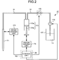
- FIG. 2 schematically shows a structure of the specimen dispensing unit 17.
- the specimen dispensing unit 17 shown in FIG. 2 includes a hollow probe 171 having a tapered tip end for absorbing and discharging the specimen; a probe driving unit 172 having an arm and the like which moves up and down the probe 171 in the vertical direction and makes the probe 171 swing in the horizontal direction; a tube 31 (a part of the duct system) constituting a flow path of a cleaning liquid Lq which supports, as a pressure transmitting medium for transmitting a pressure to the probe 171, the absorption and the discharge of the specimen by the probe 171; and a syringe 173 which generates the pressure to be applied to the probe 171 for absorbing or discharging the specimen via the cleaning liquid Lq in the tube 31.
- the syringe 173 includes a cylinder 173a and a piston 173b, and the piston 173b slides and shifts inside the cylinder 173a by a piston driving unit 174, so that the pressure to be applied to the cleaning liquid Lq in the cylinder 173a is changed.
- the syringe 173 is connected to a tube 32 constituting a part of the duct system as another flow path of the cleaning liquid Lq.
- An electromagnetic valve 175 which controls a flow of the cleaning liquid Lq and a pump 176 which performs the absorbing/discharging operation of the cleaning liquid Lq are sequentially interposed in the tube 32.
- An end of the tube 32 different from the other end connected to the syringe 173 reaches an inside of a cleaning liquid tank 177 which houses the cleaning liquid Lq.
- purified water such as ion exchanged water, water purified by a reverse osmosis membrane, distilled water, or refined water is applicable.
- purified water is generated by a purified water device provided at an outside of the automatic analyzing apparatus 1, and supplied to the cleaning liquid tank 177 via a given duct system (the purified water device and the duct system being not shown though).
- Operations including the movement of the probe 171, and the absorption and the discharge of the specimen in the probe 171 in the specimen dispensing unit 17 having the structure described above are controlled by a control unit 26 provided in the controlling/analyzing mechanism 102.
- the reagent dispensing unit 18 has the same structure as the specimen dispensing unit 17.
- a structure of a part for discharging the cleaning liquid Lq in the cleaning unit 19 is also the same as that in the specimen dispensing unit 17.
- the diluted solution dispensing unit 20 has the same structure as the specimen dispensing unit 17 (the probe driving unit in this case may not include the swing function in the horizontal direction, though), and discharges the cleaning liquid Lq as a diluted solution into the reaction vessel 141.
- all of the cleaning liquid Lq used in the reagent dispensing unit 18, the cleaning unit 19, and the diluted solution dispensing unit 20 is supplied from the cleaning liquid tank 177.
- a reagent vessel retainer 13 for a first reagent and another reagent vessel retainer 13 for a second reagent may be separately provided.
- the stirring unit 15 may be provided in plural number so that liquid in a plurality of reaction vessels 141 is simultaneously stirred at an appropriate timing after the dispense of the specimen, the reagent, or the diluted solution.
- FIG. 1 is present with a main aim of schematically showing principal components of the measuring mechanism 101, and therefore a positional relationship among the components is not necessarily accurate.
- An accurate positional relationship among the components attributes to a design particular to be determined depending on various conditions including the number of reagent vessel retainers 13 and a rotation mode of the wheel of the reaction vessel retainer 14 during an interval of the dispensing operation.
- the controlling/analyzing mechanism 102 includes an input unit 21 which accepts an input of information necessary for the analysis of the specimen and information including an operation instructing signal for instructing an operation of the automatic analyzing apparatus 1; an output unit 22 which outputs information concerning the analysis of the specimen; a data generating unit 23 which generates analysis data of the specimen based on the measurement result in the measuring mechanism 101; a quality determining unit 24 which determines the quality of the analysis supporting liquid by using the analysis data generated by the data generating unit 23; a storage unit 25 which stores various types of information including the information concerning the analysis of the specimen and concerning the automatic analyzing apparatus 1; and a control unit 26 which performs a control of each function or each unit in the controlling/analyzing mechanism 102 and a driving control of the measuring mechanism 101.
- the input unit 21 includes a keyboard and a mouse. Besides, a pointing device such as a trackball and a trackpad, and a user interface such as a microphone for an audio input may further be provided as the input unit 21.
- the output unit 22 includes a display device such as a liquid crystal display, a plasma display, an organic EL display, and a CRT display, which displays various types of information. Besides, a speaker for an output and a printer which outputs information by printing on paper may further be provided as the output unit 22.
- the data generating unit 23 performs an analyzing calculation of the measurement result received from the photometric unit 16 of the measuring mechanism 101.
- analysis data for each specimen is generated by calculating an absorbance of the liquid in the reaction vessel 141 based on the measurement result transmitted from the photometric unit 16 and performing an ingredient amount calculating processing and the like which uses the result of the absorbance calculation and various information such as a calibration curve and analysis parameters to quantitatively calculates an ingredient in the liquid in the reaction vessel 141.
- the analysis data generated in this manner is output from the output unit 22, and at the same time written and stored in the storage unit 25.
- the quality determining unit 24 compares the analysis data generated by the data generating unit 23 with reference data stored in the storage unit 25 to determine the quality of the cleaning liquid Lq.
- the storage unit 25 is realized by using a hard disk which magnetically stores various information and a memory which, when the automatic analyzing apparatus 1 executes a processing, loads from the hard disk and electrically stores a program of the processing, and stores and manages an analysis item, specimen information, a kind of specimen, a dispensing amount of the specimen and the reagent, an expiration date of the specimen and the reagent, information concerning the calibration curve used for the analysis, an expiration date of the calibration curve, parameters such as a reference value and a tolerance of each analysis item, necessary for the analysis, the analysis data generated by the data generating unit 23, and the like.
- the program stored in the storage unit 25 includes a program which causes the automatic analyzing apparatus 1 to execute a quality control method (to be described later) for the analysis supporting liquid in the automatic analyzing apparatus according to the embodiment.
- the storage unit 25 may be provided with an auxiliary storage device which reads out information recorded in a recording medium such as a flexible disk, a CD-ROM, a DVD-ROM, and a flash memory, which can be read out by a computer, and the program described above can be recorded in such a recording medium.
- the control unit 26 is realized by a CPU (Central Processing Unit) having a controlling function and a calculating function, and executes a calculation and a control of various types of operations of the automatic analyzing apparatus 1 by reading out the program stored in the storage unit 25 from the storage unit 25.
- CPU Central Processing Unit
- the controlling/analyzing mechanism 102 having the functional structure described above is realized by using one computer or a plurality of computers.
- the controlling/analyzing mechanism 102 is realized by using a plurality of computers, it is only necessary to decentralize functions of the controlling/analyzing mechanism 102 arbitrarily to different computers, and to connect the computers directly to each other or by way of a communication network (the Internet, an intranet, a leased line network, a local area network, a telephone network, and the like) to each other.
- a communication network the Internet, an intranet, a leased line network, a local area network, a telephone network, and the like
- a measurement is performed by using, as a specimen, the cleaning liquid Lq which is the analysis supporting liquid (step S1). Specifically, the cleaning liquid Lq and the reagent are dispensed into the reaction vessel 141 and the photometric unit 16 performs an optical measurement with respect to the dispensed liquid (liquid mixture of the cleaning liquid Lq and the reagent) in the reaction vessel 141.
- the measurement by the photometric unit 16 here is performed during a rotation of the reaction vessel retainer 14.
- the cleaning liquid Lq to be dispensed at step S1 is filled in a probe of any one of the specimen dispensing unit 17, the reagent dispensing unit 18, the cleaning unit 19, and the diluted solution dispensing unit 20.
- the cleaning liquid Lq in any relevant probe may be directly discharged into the reaction vessel 141, or the cleaning liquid Lq in any relevant probe may be discharged into the specimen vessel 121 whose inside is empty or the reaction vessel 141 once and then a predetermined amount of the discharged cleaning liquid Lq may be absorbed via the probe and discharged into the reaction vessel 141, similarly to a normal specimen.
- the processing at step S1 can be performed with respect to a plurality of test items different to each other, similarly to the analysis operation for the normal specimen.
- the dispensing operation in this case depends on each test item, and there is a case of dispensing the reagent prior to dispensing the cleaning liquid Lq and there is another case of dispensing the cleaning liquid Lq as a specimen in an interval of dispensing two kinds of reagents, for example. In addition, there is still another case of dispensing only the cleaning liquid Lq. Therefore, each of the dispensing timing and the photometry timing is controlled by the control unit 26 for each test item.
- the data generating unit 23 generates analysis data for each test item by using the measurement result obtained at step S1 (step S2).
- a processing of generating the analysis data at step S2 is performed similarly to the processing of generating the analysis data with respect to the normal specimen.
- the quality determining unit 24 determines the quality of the cleaning liquid Lq by comparing the analysis data generated at step S3 with given reference data (step S3). Then, the output unit 22 outputs the determination result (step S4).
- FIG. 4 shows an output example of displaying, in the output unit 22, the result of the quality determination of the cleaning liquid Lq.
- a table T shown in FIG. 4 shows an output example of displaying a determination result in a case of performing a quality determination of the cleaning liquid Lq filled in the probe 171 of the specimen dispensing unit 17 with respect to five kinds of test items A to E whose normal range are different from each other in the reference data.
- test items A to E whose normal range are different from each other in the reference data.
- only the test item C results in being out of the normal range. Therefore, only the test item C is displayed as being "abnormal" and the other test items A, B, D, and E are displayed as being "normal".
- step S6 it is determined whether or not to discontinue, with respect to all test items, the analysis on the normal specimen to be performed after the quality control processing for the analysis supporting liquid.
- the control unit 26 performs a setting for discontinueing the analysis with respect to all the test items (step S7). Due to this, the operation of the automatic analyzing apparatus 1 stops. In this case, a user is supposed to perform a maintenance including an exchange of the cleaning liquid Lq, and a cleaning of the cleaning liquid tank 177 and the tubes 31 and 32 after the operation of the automatic analyzing apparatus 1 stops.
- the control unit 26 performs a setting based on a predetermined rule (step S8).
- a predetermined rule here, the analysis on the normal specimen can be discontinued with respect to only the test item determined to be abnormal, for example.
- the analysis operation which should be performed thereafter may be set depending on the number or the kind of the test items determined to be abnormal.
- the quality control for the analysis supporting liquid in the automatic analyzing apparatus described above is automatically performed when the automatic analyzing apparatus 1 becomes a standby mode after being powered, the quality control for the analysis supporting liquid can be performed regularly.
- the setting may be made such that the quality control method for the analysis supporting liquid in the automatic analyzing apparatus described above can be performed whenever the analysis of the normal specimen has been performed predetermined number of times or for a predetermined time period, or whenever the user inputs an operation signal from the input unit 21.
- the output unit 22 may output to display information including a content which encourages the user to select a subsequent operation of the automatic analyzing apparatus 1.
- the automatic analyzing apparatus 1 is supposed to perform an operation according to the content input by the user from the input unit 21.
- the analysis supporting liquid which supports an analysis of a specimen is dispensed into the reaction vessel by using the specimen dispensing unit which dispenses a specimen, the reagent dispensing unit which dispenses a reagent, the cleaning unit which cleans the reaction vessel, or the diluted solution dispensing unit which dispenses a diluted solution, an optical measurement is performed with respect to the liquid including the dispensed analysis supporting liquid in the reaction vessel, analysis data of the analysis supporting liquid is generated by using the measured result, and the quality of the analysis supporting liquid is determined by comparing the generated analysis data with reference data, it is possible to accurately determine the quality of the analysis supporting liquid, after being supplied to the automatic analyzing apparatus, which supports an analysis in the automatic analyzing apparatus and to properly maintain the accuracy of the analysis.
- the embodiment since whether the quality, in an ultimate state just before being used, of the analysis supporting liquid used in the automatic analyzing apparatus affects analysis data or not is measured as analysis data, and when an abnormality is present, an operation control and a notification of the abnormality to the user are performed according to the abnormality, it is possible to prevent performing an analysis with the state having the abnormality in the quality of the analysis supporting liquid left as it is, and prevent an occurrence of an abnormality in analysis data. As a result of this, it is possible to eliminate a waste of an effort and a time conventionally spent until a cause of the abnormality in the analysis data is specified as lying in a deterioration of the analysis supporting liquid after the occurrence of the abnormality in the analysis data, and to realize more efficient analysis.
- the measurement result with respect to the analysis supporting liquid is obtained as analysis data, it becomes possible to clearly determine a degree of the influence on the analysis on the normal specimen.
- the prevent invention can be applied to an automatic analyzing apparatus which performs an immunological analysis on ingredients of a specimen.
- a buffering solution such as a physiological saline for performing a B/F cleaning is used. Therefore, when the present invention is applied to the automatic analyzing apparatus used for the immunological analysis using the heterogeneous reaction, the quality control processing may be performed by using purified water before generating the buffering solution as the analysis supporting liquid, or the quality control processing may be performed by using the buffering solution itself as the analysis supporting liquid.
- the automatic analyzing apparatus in this case requires a B/F cleaning unit which performs the B/F cleaning and a photomultiplier tube which, as the photometric unit, counts an amount of luminescence of a light emitting substance. Except for these points, the structure of this automatic analyzing apparatus is almost the same as that of the automatic analyzing apparatus described above.
- a case of using an enzyme called alkali phosphatase (ALP) as a labeled substance to perform a test for the HBsAg infection will be explained below.
- ALP alkali phosphatase
- a cutoff value (included in the reference data) as a boundary value for determining between positive and negative is set to 3800 counts. Since the ALP is not contained in purified water used in generating the buffering solution essentially, a counted value which provides an amount of luminescence at a time of adding a luminescent reagent into the ALP is about 300 in normal cases (the numeric value here is just shown as one example in the test for the HBsAg infection).
- the ALP is present a lot in the natural world and can easily adhere to a hand of human beings. For this reason, there is a possibility that the purified water is polluted due to the ALP adhering to the human hand. In such a case, the value counted after the luminescent reagent is added into the polluted purified water can possibly increase up to about several thousands of counts. Therefore, once the purified water is polluted by the ALP present in the natural world, there arises a possibility that the analysis data shows an excess of the cutoff value and causes a wrong determination that the specimen which is supposed to be essentially negative should be positive.
- an abnormality in the quality of an analysis supporting liquid such as purified water can be accurately detected, and thereby a wrong determination of analysis data can be prevented and an accuracy of the analysis can be properly maintained.
- the present invention is useful in performing a quality control for an analysis supporting liquid which is used when a specimen and a reagent are made react to perform an analysis on the specimen.
Claims (6)
- Procédé de contrôle qualité pour un liquide support d'analyse dans un appareil d'analyse automatique (1) qui comprend, pour réaliser une analyse sur un échantillon, une unité de distribution d'échantillon (17) qui distribue l'échantillon en utilisant, comme milieu de transmission de pression, un liquide support d'analyse comprenant de l'eau purifiée et servant à supporter l'analyse sur l'échantillon, une unité de distribution de réactif (18) qui distribue un réactif en utilisant le liquide support d'analyse comme milieu de transmission de pression, une unité de nettoyage (19) qui nettoie, en utilisant le liquide support d'analyse comme liquide de nettoyage, un réacteur (141) dans lequel l'échantillon et le réactif sont mélangés et amenés à réagir l'un avec l'autre, et une unité de distribution de solution diluée (20) qui distribue une solution diluée comprenant le liquide support d'analyse, et qui contrôle une qualité du liquide support d'analyse, le procédé de contrôle qualité comprenant :une étape de distribution pour distribuer le liquide support d'analyse au réacteur (141) par l'une parmi l'unité de distribution d'échantillon (17), l'unité de distribution de réactif (18), l'unité de nettoyage (19) et l'unité de distribution de solution diluée (20) ;une étape de photométrie pour réaliser une mesure optique vis-à-vis d'un liquide, comprenant le liquide support d'analyse distribué dans l'étape de distribution, dans le réacteur (141) ;une étape de génération de données pour générer des données d'analyse du liquide support d'analyse en utilisant un résultat mesuré dans l'étape de photométrie ; etune étape de détermination de qualité pour déterminer la qualité du liquide support d'analyse en comparant les données d'analyse, générées dans l'étape de génération de données, à des données de référence,lorsqu'une anomalie est déterminée dans l'étape de détermination de qualité, le procédé de contrôle qualité comprenant en outre une étape de commande pour réaliser une commande d'interruption d'au moins une analyse vis-à-vis d'un élément d'essai se rapportant à l'anomalie parmi des analyses à réaliser sur l'échantillon.
- Procédé de contrôle qualité pour le liquide support d'analyse dans l'appareil d'analyse automatique (1) selon la revendication 1, dans lequel le liquide dans le réacteur (141), avant d'être soumis à la mesure optique dans l'étape de photométrie, est un mélange liquide du liquide support d'analyse et d'un réactif correspondant à un élément d'essai.
- Procédé de contrôle qualité pour le liquide support d'analyse dans l'appareil d'analyse automatique (1) selon l'une quelconque des revendications 1 et 2, comprenant en outre une étape de sortie pour délivrer en sortie des informations comprenant un résultat de détermination dans l'étape de détermination de qualité.
- Appareil d'analyse automatique (1), comprenant :une unité de distribution d'échantillon (17) qui distribue un échantillon en utilisant, comme milieu de transmission de pression, un liquide support d'analyse comprenant de l'eau purifiée et servant à supporter une analyse sur l'échantillon ;une unité de distribution de réactif (18) qui distribue un réactif en utilisant le liquide support d'analyse comme milieu de transmission de pression ;une unité de nettoyage (19) qui nettoie, en utilisant le liquide support d'analyse comme liquide de nettoyage, un réacteur (141) dans lequel l'échantillon et le réactif sont mélangés et amenés à réagir l'un avec l'autre ;une unité de distribution de solution diluée (20) qui distribue une solution diluée comprenant le liquide support d'analyse ;une unité photométrique (16) qui réalise une mesure optique vis-à-vis d'un liquide comprenant le liquide support d'analyse distribué dans le réacteur (141) par l'une parmi l'unité de distribution d'échantillon (17), l'unité de distribution de réactif (18), l'unité de nettoyage (19) et l'unité de distribution de solution diluée (20) ;une unité de génération de données (23) qui utilise un résultat mesuré par l'unité photométrique (16) pour générer des données d'analyse du liquide support d'analyse ;une unité de détermination de qualité (24) qui compare les données d'analyse, générées par l'unité de génération de données (23), à des données de référence pour déterminer si une qualité du liquide support d'analyse présente une anomalie ; etune unité de commande (26) qui, lorsque la qualité du liquide support d'analyse est déterminée comme présentant une anomalie par l'unité de détermination de qualité (24), réalise une commande d'interruption d'au moins une analyse vis-à-vis d'un élément d'essai se rapportant à l'anomalie parmi des analyses à réaliser sur l'échantillon.
- Appareil d'analyse automatique (1) selon la revendication 4, dans lequel le liquide dans le réacteur (141), avant d'être soumis à la mesure optique réalisée par l'unité photométrique (16), est un mélange liquide du liquide support d'analyse et d'un réactif correspondant à un élément d'essai.
- Appareil d'analyse automatique (1) selon l'une quelconque des revendications 4 et 5, comprenant en outre une unité de sortie (22) qui délivre en sortie des informations comprenant un résultat déterminé par l'unité de détermination de qualité (24).
Applications Claiming Priority (2)
| Application Number | Priority Date | Filing Date | Title |
|---|---|---|---|
| JP2006109719A JP4948020B2 (ja) | 2006-04-12 | 2006-04-12 | 自動分析装置の分析支援用液体の品質管理方法および自動分析装置 |
| PCT/JP2007/058067 WO2007119785A1 (fr) | 2006-04-12 | 2007-04-12 | Procede pour le controle de la qualite d'un liquide support d'analyse d'un analyseur automatique, et analyseur automatique |
Publications (3)
| Publication Number | Publication Date |
|---|---|
| EP2009448A1 EP2009448A1 (fr) | 2008-12-31 |
| EP2009448A4 EP2009448A4 (fr) | 2017-12-06 |
| EP2009448B1 true EP2009448B1 (fr) | 2018-12-05 |
Family
ID=38609545
Family Applications (1)
| Application Number | Title | Priority Date | Filing Date |
|---|---|---|---|
| EP07741503.2A Expired - Fee Related EP2009448B1 (fr) | 2006-04-12 | 2007-04-12 | Appareil d'analyse automatique et procédé de contrôle qualité pour liquide support d'analyse dans celui-ci |
Country Status (4)
| Country | Link |
|---|---|
| US (1) | US8476073B2 (fr) |
| EP (1) | EP2009448B1 (fr) |
| JP (1) | JP4948020B2 (fr) |
| WO (1) | WO2007119785A1 (fr) |
Families Citing this family (8)
| Publication number | Priority date | Publication date | Assignee | Title |
|---|---|---|---|---|
| JP2009162622A (ja) * | 2008-01-07 | 2009-07-23 | Olympus Corp | 分析装置および管理方法 |
| JP4991586B2 (ja) * | 2008-01-31 | 2012-08-01 | 株式会社日立ハイテクノロジーズ | 自動分析装置 |
| JP2010190681A (ja) * | 2009-02-17 | 2010-09-02 | Beckman Coulter Inc | 自動分析装置とその純水管理方法 |
| JP5550364B2 (ja) * | 2010-01-26 | 2014-07-16 | シスメックス株式会社 | 試薬調製装置 |
| JP6242260B2 (ja) * | 2014-03-24 | 2017-12-06 | 日本電子株式会社 | 自動分析装置および自動分析方法 |
| KR20170014689A (ko) * | 2015-07-31 | 2017-02-08 | 가톨릭대학교 산학협력단 | 혈구분석기의 자동 정도 관리 장치 |
| JP7309467B2 (ja) * | 2019-06-11 | 2023-07-18 | キヤノンメディカルシステムズ株式会社 | 自動分析装置 |
| US20230075119A1 (en) * | 2020-02-14 | 2023-03-09 | Hitachi High-Tech Corporation | Electrolyte Analysis Device |
Family Cites Families (10)
| Publication number | Priority date | Publication date | Assignee | Title |
|---|---|---|---|---|
| US4276051A (en) * | 1980-01-28 | 1981-06-30 | Coulter Electronics, Inc. | System and program for chemical reaction observation with a moving photometer |
| JP2876411B2 (ja) * | 1989-09-25 | 1999-03-31 | 株式会社ニッテク | 自動分析装置 |
| JPH04329358A (ja) * | 1991-04-30 | 1992-11-18 | Shimadzu Corp | 自動分析装置の自動立上げ装置 |
| JPH06130072A (ja) * | 1992-10-14 | 1994-05-13 | Hitachi Ltd | 自動分析装置 |
| JP2783376B2 (ja) * | 1993-03-15 | 1998-08-06 | 株式会社日立サイエンスシステムズ | 自動化学分析装置 |
| JP3436095B2 (ja) * | 1997-09-18 | 2003-08-11 | 株式会社日立製作所 | 自動分析装置 |
| JP3704425B2 (ja) | 1997-09-24 | 2005-10-12 | オリンパス株式会社 | 自動分析装置 |
| JP2001264283A (ja) * | 2000-03-22 | 2001-09-26 | Hitachi Ltd | 電解質測定装置および測定方法 |
| JP2003294763A (ja) * | 2002-04-03 | 2003-10-15 | Toshiba Corp | 自動分析装置及びその管理システム |
| CA2513985C (fr) * | 2003-01-21 | 2012-05-29 | Illumina Inc. | Moniteur de reactions chimiques |
-
2006
- 2006-04-12 JP JP2006109719A patent/JP4948020B2/ja not_active Expired - Fee Related
-
2007
- 2007-04-12 EP EP07741503.2A patent/EP2009448B1/fr not_active Expired - Fee Related
- 2007-04-12 WO PCT/JP2007/058067 patent/WO2007119785A1/fr active Application Filing
-
2008
- 2008-10-09 US US12/248,444 patent/US8476073B2/en not_active Expired - Fee Related
Non-Patent Citations (1)
| Title |
|---|
| None * |
Also Published As
| Publication number | Publication date |
|---|---|
| JP4948020B2 (ja) | 2012-06-06 |
| EP2009448A1 (fr) | 2008-12-31 |
| EP2009448A4 (fr) | 2017-12-06 |
| WO2007119785A1 (fr) | 2007-10-25 |
| US8476073B2 (en) | 2013-07-02 |
| JP2007285708A (ja) | 2007-11-01 |
| US20090087914A1 (en) | 2009-04-02 |
Similar Documents
| Publication | Publication Date | Title |
|---|---|---|
| EP2009448B1 (fr) | Appareil d'analyse automatique et procédé de contrôle qualité pour liquide support d'analyse dans celui-ci | |
| CN101473230B (zh) | 分注装置以及自动分析装置 | |
| JP4448769B2 (ja) | 自動分析装置 | |
| EP2116850A1 (fr) | Analyseur | |
| JP2007240222A (ja) | 自動分析装置 | |
| JP2006010363A (ja) | 自動分析装置 | |
| JP4898270B2 (ja) | 液面検知装置および自動分析装置 | |
| US11143665B2 (en) | Automatic analyzer | |
| JP5231186B2 (ja) | 検体分注方法および分析装置 | |
| JP7204878B2 (ja) | 自動分析装置および自動分析方法 | |
| JP2008076342A (ja) | 自動分析装置 | |
| JP2008190959A (ja) | 自動分析装置 | |
| JP5711564B2 (ja) | 自動分析機 | |
| CN104487848B (zh) | 维护支持系统 | |
| JP2007322394A (ja) | 分注装置および自動分析装置 | |
| JP2011149831A (ja) | 自動分析装置 | |
| US20230341425A1 (en) | Automatic analyzer and dispensing method of reagent | |
| JP2009047638A (ja) | 自動分析装置 | |
| JP5506189B2 (ja) | 自動分析装置 | |
| JP2007322246A (ja) | 自動分析装置 | |
| JP2007285920A (ja) | 分析装置 | |
| JP2007263752A (ja) | 自動分析装置の検体分注方法、自動分析装置、およびプログラム | |
| JP2009014411A (ja) | 分注装置および自動分析装置 | |
| JP2007315785A (ja) | 自動分析装置、自動分析装置の分析続行可否判定方法、および自動分析装置の分析続行可否判定用プログラム | |
| JP7106376B2 (ja) | 自動分析装置 |
Legal Events
| Date | Code | Title | Description |
|---|---|---|---|
| PUAI | Public reference made under article 153(3) epc to a published international application that has entered the european phase |
Free format text: ORIGINAL CODE: 0009012 |
|
| 17P | Request for examination filed |
Effective date: 20081028 |
|
| AK | Designated contracting states |
Kind code of ref document: A1 Designated state(s): AT BE BG CH CY CZ DE DK EE ES FI FR GB GR HU IE IS IT LI LT LU LV MC MT NL PL PT RO SE SI SK TR |
|
| AX | Request for extension of the european patent |
Extension state: AL BA HR MK RS |
|
| DAX | Request for extension of the european patent (deleted) | ||
| RBV | Designated contracting states (corrected) |
Designated state(s): DE FR GB |
|
| RAP1 | Party data changed (applicant data changed or rights of an application transferred) |
Owner name: BECKMAN COULTER, INC. |
|
| RAP1 | Party data changed (applicant data changed or rights of an application transferred) |
Owner name: BECKMAN COULTER, INC. |
|
| RA4 | Supplementary search report drawn up and despatched (corrected) |
Effective date: 20171107 |
|
| RIC1 | Information provided on ipc code assigned before grant |
Ipc: G01N 35/00 20060101AFI20171030BHEP |
|
| REG | Reference to a national code |
Ref country code: DE Ref legal event code: R079 Ref document number: 602007057039 Country of ref document: DE Free format text: PREVIOUS MAIN CLASS: G01N0035000000 Ipc: G01N0035020000 |
|
| GRAP | Despatch of communication of intention to grant a patent |
Free format text: ORIGINAL CODE: EPIDOSNIGR1 |
|
| STAA | Information on the status of an ep patent application or granted ep patent |
Free format text: STATUS: GRANT OF PATENT IS INTENDED |
|
| RIC1 | Information provided on ipc code assigned before grant |
Ipc: G01N 35/02 20060101AFI20180607BHEP |
|
| INTG | Intention to grant announced |
Effective date: 20180628 |
|
| GRAS | Grant fee paid |
Free format text: ORIGINAL CODE: EPIDOSNIGR3 |
|
| GRAA | (expected) grant |
Free format text: ORIGINAL CODE: 0009210 |
|
| GRAA | (expected) grant |
Free format text: ORIGINAL CODE: 0009210 |
|
| STAA | Information on the status of an ep patent application or granted ep patent |
Free format text: STATUS: THE PATENT HAS BEEN GRANTED |
|
| AK | Designated contracting states |
Kind code of ref document: B1 Designated state(s): DE FR GB |
|
| REG | Reference to a national code |
Ref country code: GB Ref legal event code: FG4D |
|
| REG | Reference to a national code |
Ref country code: DE Ref legal event code: R096 Ref document number: 602007057039 Country of ref document: DE |
|
| REG | Reference to a national code |
Ref country code: DE Ref legal event code: R097 Ref document number: 602007057039 Country of ref document: DE |
|
| PLBE | No opposition filed within time limit |
Free format text: ORIGINAL CODE: 0009261 |
|
| STAA | Information on the status of an ep patent application or granted ep patent |
Free format text: STATUS: NO OPPOSITION FILED WITHIN TIME LIMIT |
|
| REG | Reference to a national code |
Ref country code: DE Ref legal event code: R119 Ref document number: 602007057039 Country of ref document: DE |
|
| 26N | No opposition filed |
Effective date: 20190906 |
|
| GBPC | Gb: european patent ceased through non-payment of renewal fee |
Effective date: 20190412 |
|
| PG25 | Lapsed in a contracting state [announced via postgrant information from national office to epo] |
Ref country code: DE Free format text: LAPSE BECAUSE OF NON-PAYMENT OF DUE FEES Effective date: 20191101 Ref country code: GB Free format text: LAPSE BECAUSE OF NON-PAYMENT OF DUE FEES Effective date: 20190412 |
|
| PG25 | Lapsed in a contracting state [announced via postgrant information from national office to epo] |
Ref country code: FR Free format text: LAPSE BECAUSE OF NON-PAYMENT OF DUE FEES Effective date: 20190430 |