EP2006560A2 - Cage et palier en resine - Google Patents
Cage et palier en resine Download PDFInfo
- Publication number
- EP2006560A2 EP2006560A2 EP07737908A EP07737908A EP2006560A2 EP 2006560 A2 EP2006560 A2 EP 2006560A2 EP 07737908 A EP07737908 A EP 07737908A EP 07737908 A EP07737908 A EP 07737908A EP 2006560 A2 EP2006560 A2 EP 2006560A2
- Authority
- EP
- European Patent Office
- Prior art keywords
- resin
- cage
- resin composition
- bearing
- main body
- Prior art date
- Legal status (The legal status is an assumption and is not a legal conclusion. Google has not performed a legal analysis and makes no representation as to the accuracy of the status listed.)
- Granted
Links
Images


Classifications
-
- F—MECHANICAL ENGINEERING; LIGHTING; HEATING; WEAPONS; BLASTING
- F16—ENGINEERING ELEMENTS AND UNITS; GENERAL MEASURES FOR PRODUCING AND MAINTAINING EFFECTIVE FUNCTIONING OF MACHINES OR INSTALLATIONS; THERMAL INSULATION IN GENERAL
- F16C—SHAFTS; FLEXIBLE SHAFTS; ELEMENTS OR CRANKSHAFT MECHANISMS; ROTARY BODIES OTHER THAN GEARING ELEMENTS; BEARINGS
- F16C33/00—Parts of bearings; Special methods for making bearings or parts thereof
- F16C33/30—Parts of ball or roller bearings
- F16C33/38—Ball cages
- F16C33/44—Selection of substances
-
- F—MECHANICAL ENGINEERING; LIGHTING; HEATING; WEAPONS; BLASTING
- F02—COMBUSTION ENGINES; HOT-GAS OR COMBUSTION-PRODUCT ENGINE PLANTS
- F02K—JET-PROPULSION PLANTS
- F02K9/00—Rocket-engine plants, i.e. plants carrying both fuel and oxidant therefor; Control thereof
- F02K9/42—Rocket-engine plants, i.e. plants carrying both fuel and oxidant therefor; Control thereof using liquid or gaseous propellants
- F02K9/60—Constructional parts; Details not otherwise provided for
-
- F—MECHANICAL ENGINEERING; LIGHTING; HEATING; WEAPONS; BLASTING
- F04—POSITIVE - DISPLACEMENT MACHINES FOR LIQUIDS; PUMPS FOR LIQUIDS OR ELASTIC FLUIDS
- F04D—NON-POSITIVE-DISPLACEMENT PUMPS
- F04D29/00—Details, component parts, or accessories
- F04D29/02—Selection of particular materials
- F04D29/023—Selection of particular materials especially adapted for elastic fluid pumps
-
- F—MECHANICAL ENGINEERING; LIGHTING; HEATING; WEAPONS; BLASTING
- F04—POSITIVE - DISPLACEMENT MACHINES FOR LIQUIDS; PUMPS FOR LIQUIDS OR ELASTIC FLUIDS
- F04D—NON-POSITIVE-DISPLACEMENT PUMPS
- F04D29/00—Details, component parts, or accessories
- F04D29/02—Selection of particular materials
- F04D29/026—Selection of particular materials especially adapted for liquid pumps
-
- F—MECHANICAL ENGINEERING; LIGHTING; HEATING; WEAPONS; BLASTING
- F04—POSITIVE - DISPLACEMENT MACHINES FOR LIQUIDS; PUMPS FOR LIQUIDS OR ELASTIC FLUIDS
- F04D—NON-POSITIVE-DISPLACEMENT PUMPS
- F04D29/00—Details, component parts, or accessories
- F04D29/04—Shafts or bearings, or assemblies thereof
- F04D29/046—Bearings
- F04D29/049—Roller bearings
-
- F—MECHANICAL ENGINEERING; LIGHTING; HEATING; WEAPONS; BLASTING
- F04—POSITIVE - DISPLACEMENT MACHINES FOR LIQUIDS; PUMPS FOR LIQUIDS OR ELASTIC FLUIDS
- F04D—NON-POSITIVE-DISPLACEMENT PUMPS
- F04D29/00—Details, component parts, or accessories
- F04D29/05—Shafts or bearings, or assemblies thereof, specially adapted for elastic fluid pumps
- F04D29/056—Bearings
- F04D29/059—Roller bearings
-
- F—MECHANICAL ENGINEERING; LIGHTING; HEATING; WEAPONS; BLASTING
- F16—ENGINEERING ELEMENTS AND UNITS; GENERAL MEASURES FOR PRODUCING AND MAINTAINING EFFECTIVE FUNCTIONING OF MACHINES OR INSTALLATIONS; THERMAL INSULATION IN GENERAL
- F16C—SHAFTS; FLEXIBLE SHAFTS; ELEMENTS OR CRANKSHAFT MECHANISMS; ROTARY BODIES OTHER THAN GEARING ELEMENTS; BEARINGS
- F16C33/00—Parts of bearings; Special methods for making bearings or parts thereof
- F16C33/30—Parts of ball or roller bearings
- F16C33/38—Ball cages
- F16C33/3831—Ball cages with hybrid structure, i.e. with parts made of distinct materials
-
- F—MECHANICAL ENGINEERING; LIGHTING; HEATING; WEAPONS; BLASTING
- F16—ENGINEERING ELEMENTS AND UNITS; GENERAL MEASURES FOR PRODUCING AND MAINTAINING EFFECTIVE FUNCTIONING OF MACHINES OR INSTALLATIONS; THERMAL INSULATION IN GENERAL
- F16C—SHAFTS; FLEXIBLE SHAFTS; ELEMENTS OR CRANKSHAFT MECHANISMS; ROTARY BODIES OTHER THAN GEARING ELEMENTS; BEARINGS
- F16C33/00—Parts of bearings; Special methods for making bearings or parts thereof
- F16C33/30—Parts of ball or roller bearings
- F16C33/66—Special parts or details in view of lubrication
- F16C33/6696—Special parts or details in view of lubrication with solids as lubricant, e.g. dry coatings, powder
-
- F—MECHANICAL ENGINEERING; LIGHTING; HEATING; WEAPONS; BLASTING
- F05—INDEXING SCHEMES RELATING TO ENGINES OR PUMPS IN VARIOUS SUBCLASSES OF CLASSES F01-F04
- F05D—INDEXING SCHEME FOR ASPECTS RELATING TO NON-POSITIVE-DISPLACEMENT MACHINES OR ENGINES, GAS-TURBINES OR JET-PROPULSION PLANTS
- F05D2300/00—Materials; Properties thereof
- F05D2300/40—Organic materials
- F05D2300/43—Synthetic polymers, e.g. plastics; Rubber
- F05D2300/432—PTFE [PolyTetraFluorEthylene]
-
- F—MECHANICAL ENGINEERING; LIGHTING; HEATING; WEAPONS; BLASTING
- F05—INDEXING SCHEMES RELATING TO ENGINES OR PUMPS IN VARIOUS SUBCLASSES OF CLASSES F01-F04
- F05D—INDEXING SCHEME FOR ASPECTS RELATING TO NON-POSITIVE-DISPLACEMENT MACHINES OR ENGINES, GAS-TURBINES OR JET-PROPULSION PLANTS
- F05D2300/00—Materials; Properties thereof
- F05D2300/50—Intrinsic material properties or characteristics
- F05D2300/509—Self lubricating materials; Solid lubricants
-
- F—MECHANICAL ENGINEERING; LIGHTING; HEATING; WEAPONS; BLASTING
- F16—ENGINEERING ELEMENTS AND UNITS; GENERAL MEASURES FOR PRODUCING AND MAINTAINING EFFECTIVE FUNCTIONING OF MACHINES OR INSTALLATIONS; THERMAL INSULATION IN GENERAL
- F16C—SHAFTS; FLEXIBLE SHAFTS; ELEMENTS OR CRANKSHAFT MECHANISMS; ROTARY BODIES OTHER THAN GEARING ELEMENTS; BEARINGS
- F16C19/00—Bearings with rolling contact, for exclusively rotary movement
- F16C19/02—Bearings with rolling contact, for exclusively rotary movement with bearing balls essentially of the same size in one or more circular rows
- F16C19/14—Bearings with rolling contact, for exclusively rotary movement with bearing balls essentially of the same size in one or more circular rows for both radial and axial load
- F16C19/16—Bearings with rolling contact, for exclusively rotary movement with bearing balls essentially of the same size in one or more circular rows for both radial and axial load with a single row of balls
- F16C19/163—Bearings with rolling contact, for exclusively rotary movement with bearing balls essentially of the same size in one or more circular rows for both radial and axial load with a single row of balls with angular contact
-
- F—MECHANICAL ENGINEERING; LIGHTING; HEATING; WEAPONS; BLASTING
- F16—ENGINEERING ELEMENTS AND UNITS; GENERAL MEASURES FOR PRODUCING AND MAINTAINING EFFECTIVE FUNCTIONING OF MACHINES OR INSTALLATIONS; THERMAL INSULATION IN GENERAL
- F16C—SHAFTS; FLEXIBLE SHAFTS; ELEMENTS OR CRANKSHAFT MECHANISMS; ROTARY BODIES OTHER THAN GEARING ELEMENTS; BEARINGS
- F16C2208/00—Plastics; Synthetic resins, e.g. rubbers
- F16C2208/20—Thermoplastic resins
- F16C2208/30—Fluoropolymers
- F16C2208/32—Polytetrafluorethylene [PTFE]
-
- F—MECHANICAL ENGINEERING; LIGHTING; HEATING; WEAPONS; BLASTING
- F16—ENGINEERING ELEMENTS AND UNITS; GENERAL MEASURES FOR PRODUCING AND MAINTAINING EFFECTIVE FUNCTIONING OF MACHINES OR INSTALLATIONS; THERMAL INSULATION IN GENERAL
- F16C—SHAFTS; FLEXIBLE SHAFTS; ELEMENTS OR CRANKSHAFT MECHANISMS; ROTARY BODIES OTHER THAN GEARING ELEMENTS; BEARINGS
- F16C2208/00—Plastics; Synthetic resins, e.g. rubbers
- F16C2208/20—Thermoplastic resins
- F16C2208/36—Polyarylene ether ketones [PAEK], e.g. PEK, PEEK
-
- F—MECHANICAL ENGINEERING; LIGHTING; HEATING; WEAPONS; BLASTING
- F16—ENGINEERING ELEMENTS AND UNITS; GENERAL MEASURES FOR PRODUCING AND MAINTAINING EFFECTIVE FUNCTIONING OF MACHINES OR INSTALLATIONS; THERMAL INSULATION IN GENERAL
- F16C—SHAFTS; FLEXIBLE SHAFTS; ELEMENTS OR CRANKSHAFT MECHANISMS; ROTARY BODIES OTHER THAN GEARING ELEMENTS; BEARINGS
- F16C2300/00—Application independent of particular apparatuses
- F16C2300/40—Application independent of particular apparatuses related to environment, i.e. operating conditions
- F16C2300/52—Application independent of particular apparatuses related to environment, i.e. operating conditions low temperature, e.g. cryogenic temperature
-
- F—MECHANICAL ENGINEERING; LIGHTING; HEATING; WEAPONS; BLASTING
- F16—ENGINEERING ELEMENTS AND UNITS; GENERAL MEASURES FOR PRODUCING AND MAINTAINING EFFECTIVE FUNCTIONING OF MACHINES OR INSTALLATIONS; THERMAL INSULATION IN GENERAL
- F16C—SHAFTS; FLEXIBLE SHAFTS; ELEMENTS OR CRANKSHAFT MECHANISMS; ROTARY BODIES OTHER THAN GEARING ELEMENTS; BEARINGS
- F16C2360/00—Engines or pumps
- F16C2360/42—Pumps with cylinders or pistons
Definitions
- the present invention relates to a cage made of resin and more particularly to a cage made of resin suitable for a bearing which is used in a cryogenic-temperature environment in which liquid hydrogen, liquid oxygen, liquid nitrogen, LNG, and the like are used or used in a vacuum.
- rolling elements such as balls and cylindrical rollers are arranged in a raceway space disposed between an inner ring and an outer ring, and the rolling elements are retained by a cage.
- the cage is guided at an inner-ring side or an outer-ring side.
- An angular contact ball bearing used in a rotation-supporting portion of a turbopump, of a rocket engine, which uses a liquid fuel is a representative example of a bearing used in the low-temperature environment.
- Fig. 3 shows an example of the construction of an angular contact ball bearing 1 for use in the turbopump.
- the bearing is constructed of four kinds of component parts including an inner ring 2, an outer ring 3, a plurality of balls 4a serving as rolling elements 4, and a cage 5.
- the inner ring 2 and the outer ring 3 contact the balls 4a at a predetermined angle ⁇ (contact angle) to a radial center line A.
- ⁇ contact angle
- PTFE polytetrafluoroethylene resin
- Fig. 4 shows an example of conventional cages having a pocket portion.
- Fig. 4 (a) is a perspective view of the cage.
- Fig. 4 (b) is a side elevation of a section D-D of Fig. 4(a) .
- a method of forming the main body of the cage 5 of the PTFE and a method of forming the main body thereof of a metal are used.
- the main body of the cage 5 of the metal In a known method of forming the main body of the cage 5 of the metal, the main body of the cage 5 and the pocket portion 5a are formed by mechanical processing and the pocket member made of the PTFE is inserted into the cage (patent document 2).
- the main body of the cage 5 is made of the composite material consisting of the sintered cylindrically layered glass woven cloths impregnated with the PTFE. Therefore the patent document 1 has a problem of (1) : The material is very expensive, (2) : After the material is processed into the shape of the cage, the hydrogen fluoride is required to dissolve the glass fiber present on the surface to be processed. Thus the production cost is very high, and (3) : Because the method of producing the material is special, the productivity is low, and a long lead time is necessary.
- the present invention has been made to cope with the above-described problems. It is an object of the present invention to provide a cage made of resin that can be used in a cryogenic-temperature environment or in a vacuum without providing the cage with a complicated construction and without performing special treatment; and a bearing which uses the cage.
- a cage of the present invention made of resin has an annular main body having a plurality of pocket portions radially penetrating the main body and a plurality of pocket members, provided on the annular main body, which hold rolling elements of a rolling bearing.
- the main body of the cage is a molding of a first resin composition consisting of a first resin and a solid lubricant mixed therewith.
- At least a rolling element-retaining surface of each of the pocket members is made of a second resin composition containing fluorocarbon resin as a main component thereof.
- the molding of the first resin composition has a tensile strength of not less than 30 MPa and a heat-resistant temperature of not less than 200°C.
- the tensile strength is measured by the method of JIS K7161.
- the heat-resistant temperature is measured by the method of ASTM D648.
- the first resin includes at least one resin selected from the group consisting of aromatic polyether ether ketone and polyphenylene sulfide.
- the solid lubricant contained in the first resin composition is PTFE.
- a mixing ratio of the solid lubricant to an entirety of the first resin composition is set to 10 wt% to 60 wt%.
- the fluorocarbon resin is polytetrafluoroethylene resin.
- the second resin composition contains the fluorocarbon resin and a reinforcing material.
- the bearing of the present invention comprising an inner ring, an outer ring, rolling elements interposed between the inner ring and the outer ring, and a cage for retaining the rolling elements, wherein as the cage, a cage made of resin is used.
- the bearing is used for a turbopump, of a rocket engine, which uses a liquid fuel.
- the main body is a molding of the first resin composition composed of the first resin and the solid lubricant mixed therewith, and at least the rolling element-retaining surface of the pocket member holding the rolling elements of the rolling bearing is made of the second resin composition containing the fluorocarbon resin as the main component thereof. Therefore the strength of the cage and the lubricating property thereof are compatible with each other
- the molding of the first resin composition has a tensile strength of not less than 30 MPa and a heat-resistant temperature of not less than 200°C.
- the second resin composition is the fluorocarbon resin composition. Therefore the pocket member is capable of smoothly contacting the rolling elements. Further the strength of the cage and the lubricating property thereof are compatible with each other in the cryogenic-temperature environment.
- the bearing of the present invention has the inner ring, the outer ring, and the rolling elements interposed between the inner ring and the outer ring, and the cage for retaining the rolling elements.
- the cage is made of the resin. Therefore the strength of the bearing used in the cryogenic-temperature environment and the lubricating property thereof are compatible with each other.
- the bearing can be used for a turbopump, of a rocket engine, which uses a liquid fuel.
- the main body of the cage made of the resin displays an excellent mechanical strength and wear property, that the fluorocarbon resin migrates from a pocket member, mounted on the pocket portion, which is composed of the second resin composition containing the fluorocarbon resin as its main component to sliding surfaces of rolling elements and attaches thereto, and that the fluorocarbon resin which has migrated and attached to the rolling elements migrates to a raceway of each of inner and outer rings, thus providing a lubricating action.
- the present invention is based on the above-described finding.
- the resin that can be used for the first resin composition forming the main body of the cage of the present invention made of resin it is possible to use the resin which allows the first resin composition to have a tensile strength of not less than 30 MPa and a heat-resistant temperature of not less than 200°C.
- a resin super-engineering plastic is preferable.
- the super-engineering plastic which allows the resin composition to have the tensile strength of not less than 30 MPa and the heat-resistant temperature of not less than 200°C wear resistance and durability demanded for the rolling bearing can be improved.
- the heat-resistant temperatures of resins when the resins are singly used not more than 100°C in general-purpose plastics such polyethylene, polyvinyl chloride, polypropylene, polystyrene, and the like; not less than 100°C in general-purpose engineering plastics such as polyacetal, polycarbonate, modified polyphenylene ether (PPE), polybutylene terephthalate (PPB), and the like; and not less than 150°C in the super-engineering plastic.
- general-purpose plastics such polyethylene, polyvinyl chloride, polypropylene, polystyrene, and the like
- PPE modified polyphenylene ether
- PPB polybutylene terephthalate
- polyimide-based resin such as polyimide (hereinafter abbreviated as PI) , polyetherimide, polyamide-imide; polyarylene sulfide-based resin such as polyphenylene sulfide (hereinafter abbreviated as PPS); aromatic polyether ketone-based resin such as polysulfone, polyether sulfone, polyarylate, aromatic polyether ether ketone (hereinafter abbreviated as PEEK), and aromatic polyether ketone; aliphatic polyamide resin; and aromatic polyamide resin such as polyphthalamide.
- PI polyimide
- PPS polyarylene sulfide-based resin
- PEEK aromatic polyether ketone-based resin
- aliphatic polyamide resin aliphatic polyamide resin
- aromatic polyamide resin such as polyphthalamide.
- these super-engineering plastics have a heat-resistant temperature less than 200°C when they are used singly, they can be used by adjusting the heat-resistant temperature of the resin composition to not less than 200°C.
- a method of adding a heat-resistant temperature improver such as a filler to the super-engineering plastics and a method of forming a resin mixture by mixing the super-engineering plastic with other super-engineering plastic resin having a high heat-resistant temperature.
- the polyimide resin such as the PI; the polyarylene sulfide-based resin such as the PPS; the aromatic polyether ketone-based resin such as the PEEK; and aromatic thermosetting resin are preferable because these super-engineering plastics are excellent in the wear resistance and self-lubricating property thereof.
- the use of these resins allows a resin film to be formed easily on the surfaces of rolling elements.
- a material that can be injection-molded is preferable because it has a high yield and improves the productivity.
- the aromatic polyether ketone-based resin such as the PEEK and the polyarylene sulfide resin such as the PPS are especially preferable.
- the solid lubricant that can be used for the main body of the cage of the present invention made of resin it is possible to list PTFE, molybdenum disulfide, tungsten disulfide, graphite, antimony sulfide, and boron compounds such as boron nitride.
- PTFE molybdenum disulfide
- tungsten disulfide graphite
- antimony sulfide boron compounds
- boron compounds such as boron nitride.
- the PTFE that has a favorable compatibility with the super-engineering plastics, a high moldability into a cage having a complicated configuration, and is excellent in the property of lowering the friction coefficient and wear amount of a sliding portion at a cryogenic-temperature.
- the mixing ratio of the solid lubricant to the entire first resin composition is 10 to 60 wt%.
- the mixing ratio thereof is less than 10 wt%, the sliding property of the main body of the cage made of resin deteriorates, whereas when the mixing ratio thereof is more than 60 wt%, the mechanical strength of the main body of the cage made of resin deteriorates.
- the main body of the conventional cage is a calcined composite material composed of glass woven cloths cylindrically layered one upon another and impregnated with the PTFE.
- the main body of the cage has a limitation in the improvement of the mechanical strength and necessitates a long lead time before the delivery of a product.
- the main body of the conventional cage made of a metal can be produced by only molding the resin composition composed of the super-engineering plastic and the solid lubricant. Therefore mechanical processing such as machining is eliminated and thus the productivity can be improved.
- At least the rolling element-retaining surface for retaining the rolling element is made of the second resin composition containing the fluorocarbon resin as its main component.
- the main component of the fluorocarbon resin that can be used for the pocket member, as a solid lubricating component, has a migrating property in a vacuum atmosphere. More specifically, it is possible list PTFE, a tetrafluoroethylene-perfluoroalkylvinyl ether copolymer (hereafter abbreviated as PFA), an ethylene-tetrafluoroethylene copolymer (hereafter abbreviated as ETFA), a tetrafluoroethylene-hexafluoropropylene copolymer (FEP), a tetrafluoroethylene-fluoroalkylvinyl ether-fluoroolefin copolymer (EPE), a polychlorotrifluoroethylene copolymer (PCTFE), an ethylene-chlorotrifluoroethylene copolymer (ECTFE), polyvinylidene fluoride(PVDF), and polyvinyl fluoride (PVF).
- fluorocarbon resins may be used singly or as mixtures.
- the PTFE, the PFA, and the ETFA are preferable.
- the PTFE is especially favorable because it migrates and attaches to amating slidingmember and is excellent in decreasing the friction coefficient and wear amount of the sliding portion.
- the fluorocarbon resin which is the main component of the second resin composition that can be used for the pocket member of the cage of the present invention made of resin is a solid softer than materials of the inner ring, the outer ring, the rolling elements, and the cage and wears little by little owing to sliding contact between the pocket member made of the fluorocarbon resin and the materials of the inner ring, the outer ring, and the rolling elements which are mating sliding members of the pocket member caused by the rotation of the bearing to generate worn powder and forms a lubricating film on sliding surfaces between the pocket member and the inner ring, the outer ring, and the rolling element.
- the PTFE may be used singly, but to reinforce its mechanical strength, it is possible to add reinforcing materials such as a fibrous filler, various whiskers, inorganic substances, and the like as necessary.
- the reinforcing material can be used singly or in combination of not less than two kinds.
- the reinforcing material which is excellent in the migration performance to the mating slidingmembers decreases the friction coefficient of the sliding portion, and decreases the wear amount thereof.
- fibrous fillers it is possible to list carbon fibers such as PAN-based carbon fiber, pitch-based carbon fiber; and inorganic fibers including milled fiber, glass fiber, potassium titanate fiber, boron fiber, silicon carbide fiber, metal fibers such as brass, aluminum, zinc and the like; and organic fibers represented by aramid fiber.
- ceramic whiskers such as silicon carbide whisker, silicon nitride whisker, potassium titanate whisker, aluminum borate whisker, zinc oxide whisker, magnesium sulfate whisker, magnesium whisker, magnesium borate whisker, titanium diborate whisker, calcium carbonate whisker, graphite whisker,bismuth-based whisker, magnesium oxide whisker, aluminum nitride wollastonite, and magnesium pyroborate are listed.
- glass bead As inorganic substances, glass bead, wollastonite, mica, talc, kaolin, silicon dioxide, clay, asbestos, calcium carbonate, magnesium hydroxide, silica, diatomaceous earth, and Carborundum are listed. In addition, flake of aluminum and zinc, calcium fluoride, calcium oxide, magnesium oxide, and copper powder are listed.
- a laminar lubricant such as molybdenum disulfide, tungsten disulfide, and the like, an antioxidant, a heat stabilizer, an ultraviolet ray-absorbing agent, a fire retarder, an antistatic agent, a crystallization core agent, a crystallization accelerator, and the like.
- the mixing ratio of the reinforcing materials and additives to the entire second resin composition is preferably less than 50 wt%.
- the mixing ratio is not less than 50 wt%, the migrating performance of the second resin composition to the mating sliding members is inferior.
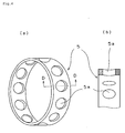
- Fig. 2(a) is a plan view of a pocket member 6.
- Fig. 2 (b) is a front view in a section C-C of Fig. 2(a) .
- the pocket member 6 has a stretched circular cylindrical portion 6a and a flange portion 6b formed on the peripheral edge of the cylindrical portion 6a.
- an adhesion method and a fit-in method can be applied.
- the adhesion method is preferable because in the adhesion method, the processing can be performed simply and workability is favorable.
- an adhesive agent an adhesive agent for a cryogenic-temperature can be used.
- a two-part type adhesive agent is preferable.
- An epoxy resin-based adhesive agent is preferable.
- the adhesive agent for the cryogenic-temperature NF Nitofix SK-299 produced by NITTO DENKO Corporation can be used.
- the cage of the present invention made of resin can be so constructed that the pocket member 6 can be mounted on the pocket portion 5a from the inner-ring side of the pocket portion 5a of the main body of the cage or from the outer-ring side of the cage.
- the pocket member 6 is pressed against the pocket portion 5a owing to a centrifugal force caused by the rotation of the bearing and can be stably fixed to the pocket portion 5a.
- the construction of mounting the pocket member 6 on the pocket portion 5a from the inner-ring side of the cage is preferable.
- the pocket member 6 is inserted from the inner-ring side of the main body of the cage with the flange portion 6b directed toward the inner-ring side of the cage.
- adhesion as shown in Fig.
- the pocket member 6 is mounted on the pocket portion 5a of the main body of the cage 5 by bonding the cylindrical portion 6a of the pocket member 6 and the outer circumferential surface of the flange portion 6b thereof to the pocket portion 5a through an adhesive layer 7 with an adhesive agent.
- the migration property of the fluorocarbon resin to the rolling elements can be adjusted in conformity to environment where the bearing is used, it is possible to improve the productivity of various kinds of bearings.
- ordinary materials for the bearing are applicable to the outer ring and the inner ring.
- martensitic stainless steel can be used.
- the martensitic stainless steel can be used for the rolling element. Ceramics can be also used therefor. When ceramics are used, silicon nitride (Si 3 N 4 ), silicon carbide (SiC), alumina (Al 2 O 3 ), zirconia (ZrO 2 ), sialon, and the like are listed.
- the bearing of the present invention has the inner ring, the outer ring, and the rolling elements interposed between the inner ring and the outer ring, and the cage for retaining the rolling elements.
- As the cage a cage made of resin is used.
- the bearing can be used for a turbopump, of a rocket engine, which uses a liquid fuel.
- the bearing of the present invention by adjusting the composition of the second resin composition composing the pocket member mounted on the pocket portion of the cage, it is possible to control the supply amount of the second resin composition in dependence on a necessary degree of sliding performance of the surface of the pocket member in sliding contact between the pocket member and the rolling elements.
- the lubricant can be supplied not only from the main body of the cage but also from the pocket member mounted on the cage. Therefore by changing components of the material for the pocket member and the ratio among the components, it is possible to adjust the migration property of the lubricant to the rolling elements in conformity to environment where the bearing is used. Therefore in addition to a use in the low-temperature environment, the applicable range of the bearing can be increased so that the bearing can be used for auxiliary machines of a car in the high-temperature environment.
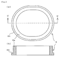
- Fig. 1 is a combination view (partly sectional view) showing a cage made of resin.
- Fig. 1(a) is a plan view;
- Fig. 1(b) is a front view of a section A-A of Fig. 1(a);
- Fig. 1(c) is a side view of a section B-B of Fig. 1(a);
- Fig. 1(d) is an enlarged view of a circled portion of Fig. 1(c) .
- the cage 5 made of resin has a plurality of the pocket portions 5a, radially penetrating an annular member, on which the pocket members 6 for accommodating the rolling elements respectively are mounted from the inner-ring side.
- the pocket member 6 is bonded to the pocket portion 5a through the adhesive layer 7.
- An enlarged view of the pocket member 6 is shown in Fig. 2 .
- the main body of the cage 5 made of resin is a molding of the first resin composition composed of PEEK and PTFE.
- Means for mixing and kneading the PEEK and the PTFE is not limited to a special means, but only a powder material is dry-blended by a Henschel mixer, a ball mixer, a ribbon blender, a Redige mixer, an ultra-Henschel mixer or the like and thereafter a mixed powder material is fused and kneaded by a fusing extruder such as a biaxial extruder to obtain a pellet (granule) to be molded.
- a fusing extruder such as a biaxial extruder to obtain a pellet (granule) to be molded.
- side feed may be adopted in fusing and kneading the mixed powder material by the biaxial extruder or the like.
- the molding method it is possible to adopt extrusion molding, injection molding, heating compression molding, and the like.
- the injection molding is especially preferable in terms of production efficiency.
- Treatment such as anneal treatment or the like may be adopted to improve the property of a product obtained by molding.
- the first resin composition it is possible to use Bearee PK5060 (tensile strength: 56 MPa, heat-resistant temperature: 250°C) and PK5300 (tensile strength: 82 MPa, heat-resistant temperature: 250°C) produced by NTN Corporation.
- the pocket member 6 mounted on the pocket portion 5a provided on the main body of the resinous cage 5 consisting of the PEEK and the PTFE consisted of the fluorocarbon resin composition.
- the fluorocarbon resin of the fluorocarbon resin composition migrates and attaches to the sliding surfaces of the rolling elements.
- the fluorocarbon resin that has migrated and attached to the rolling elements migrates to the raceway of the inner ring and the outer ring, thus providing a lubricating action.
- the fluorocarbon resin composition forming the pocket member provides a favorable result in the case where the fluorocarbon resin composition consists of the PTFE and in the case where calcium carbonate or copper powder is added to the PTFE.
- the means for mixing and kneading the fluorocarbon resin composition and the method for forming the pocket member by molding it can be carried out in a manner similar to the method of forming the main body of the cage of the first resin composition.
- an adhesive agent NF Nitofix SK-299 for a cryogenic-temperature produced by NITTO DENKO Corporation is applied to an outer circumference of the pocket member 6, and the pocket member 6 is mounted on the pocket portion 5a from the inner-ring side of the main body of the cage 5.
- the NF Nitofix SK-299 forms the stable adhesive layer 7 between the resin composition of the pocket member 6 and the resin composition of the main body of the cage 5 and absorbs a dimensional shrinkage of the resin composition of the pocket member 6 and the resin composition, of the main body of the cage 5, different from the resin composition of the pocket member 6 in the cryogenic-temperature, thus stably fixing both to each other.
- the strength and lubricating property of the cage are compatible with each other at the cryogenic-temperature.
- an adhesive agent for bonding the different materials to each other at the cryogenic-temperature an adhesive agent of the two-part type is preferable.
- the NF Nitofix SK-299 main component: epoxy resin, component of hardening agent: polyamide, mixing ratio: 1:1
- the pocket member 6 bonded to the pocket portion 5a of the cage 5 wears owing to the sliding contact between the pocket member 6 and the rolling elements to generate worn powder.
- the worn powder forms a lubricating film on the sliding surface of the pocket member 6 that slidingly contacts the rolling elements. Therefore the cage 5 withstands a use in the cryogenic-temperature environment.
- the plan configuration of the pocket portion 5a of the cage 5 and that of the pocket member 6 shown in Figs. 1 and 2 are stretched circular but may be perfectly circular.
- the stretched circular configuration means a configuration constructed of two half circles of radius approximate to the radius of the balls, which are disposed at both sides of a gap of some width. It is preferable to form the stretched circular configuration which has a large gap to absorb the delay in the advance of the balls and which is capable of decreasing a load applied to the cage.
- the bearing of the present invention is suitably used for a turbopump using liquid hydrogen or liquid oxygen. Because the liquid hydrogen or the liquid oxygen flows smoothly, it is possible to restrain the generation of heat at the contact point between the rolling elements and the raceway of the inner ring as well as the raceway of the outer ring, the sliding-contact point between the rolling elements and the surface of the pocket portion, and the sliding-contact point between the outside surface of the cage and the inside surface of the outer ring.
- the bearing of the present invention has the above-described construction, the bearing can be preferably used in the cryogenic-temperature environment in which liquid hydrogen, liquid oxygen, liquid nitrogen, LNG, and the like are used or in a vacuum.
- the bearing of the present invention can be preferably used for auxiliary machines of a car in the high-temperature environment in addition to the low-temperature environment.
Landscapes
- Engineering & Computer Science (AREA)
- General Engineering & Computer Science (AREA)
- Mechanical Engineering (AREA)
- Chemical & Material Sciences (AREA)
- Combustion & Propulsion (AREA)
- Rolling Contact Bearings (AREA)
- Structures Of Non-Positive Displacement Pumps (AREA)
Applications Claiming Priority (2)
| Application Number | Priority Date | Filing Date | Title |
|---|---|---|---|
| JP2006065547A JP5102964B2 (ja) | 2006-03-10 | 2006-03-10 | 樹脂製保持器および軸受 |
| PCT/JP2007/054394 WO2007105552A1 (fr) | 2006-03-10 | 2007-03-07 | Cage et palier en resine |
Publications (4)
| Publication Number | Publication Date |
|---|---|
| EP2006560A2 true EP2006560A2 (fr) | 2008-12-24 |
| EP2006560A9 EP2006560A9 (fr) | 2009-07-22 |
| EP2006560A4 EP2006560A4 (fr) | 2010-11-24 |
| EP2006560B1 EP2006560B1 (fr) | 2012-07-04 |
Family
ID=38509385
Family Applications (1)
| Application Number | Title | Priority Date | Filing Date |
|---|---|---|---|
| EP07737908A Active EP2006560B1 (fr) | 2006-03-10 | 2007-03-07 | Cage et palier en resine pour températures cryogéniques |
Country Status (5)
| Country | Link |
|---|---|
| US (1) | US8113718B2 (fr) |
| EP (1) | EP2006560B1 (fr) |
| JP (1) | JP5102964B2 (fr) |
| CN (1) | CN101400910B (fr) |
| WO (1) | WO2007105552A1 (fr) |
Cited By (4)
| Publication number | Priority date | Publication date | Assignee | Title |
|---|---|---|---|---|
| WO2015035987A1 (fr) * | 2013-09-12 | 2015-03-19 | Schaeffler Technologies AG & Co. KG | Cage pour un palier à roulement et palier à roulement correspondant |
| EP3006753A4 (fr) * | 2013-05-31 | 2016-11-30 | Ntn Toyo Bearing Co Ltd | Dispositif de retenue de roulement à rouleaux, roulement à rouleaux, et procédé de production de dispositif de retenue de roulement à rouleaux |
| WO2018010718A1 (fr) * | 2016-07-13 | 2018-01-18 | Schaeffler Technologies AG & Co. KG | Cage de roulement guidée par les corps de roulement ainsi que roulement comprenant une cage de ce type |
| WO2022008857A1 (fr) * | 2020-07-10 | 2022-01-13 | Safran Aircraft Engines | Insert pour palier de roulement |
Families Citing this family (13)
| Publication number | Priority date | Publication date | Assignee | Title |
|---|---|---|---|---|
| JP5211963B2 (ja) * | 2008-03-03 | 2013-06-12 | 日本精工株式会社 | 玉軸受、搬送装置、真空処理装置 |
| US20130256065A1 (en) * | 2010-10-25 | 2013-10-03 | Jeroen Bongaerts | Apparatus for use in a system containing a lubricating fluid and method of forming the same |
| DE102012208345A1 (de) * | 2012-05-18 | 2013-11-21 | Ks Gleitlager Gmbh | Gleitlagerverbundwerkstoff |
| US9528592B2 (en) | 2012-06-26 | 2016-12-27 | Kinetech Power Company Llc | Solid-lubricated bearing assembly |
| JP6234137B2 (ja) * | 2013-09-26 | 2017-11-22 | Ntn株式会社 | 深みぞ玉軸受 |
| DE102014209647A1 (de) * | 2014-05-21 | 2015-11-26 | Schaeffler Technologies AG & Co. KG | Kugellager für einen Turbolader |
| DE102014212072A1 (de) * | 2014-06-24 | 2015-12-24 | Aktiebolaget Skf | Lagerkäfig oder Lagerkäfigsegment |
| JP6395342B2 (ja) * | 2015-06-04 | 2018-09-26 | 三菱重工エンジン&ターボチャージャ株式会社 | 軸受装置、及び、過給器 |
| CN107614906B (zh) * | 2015-06-05 | 2020-04-07 | Ntn株式会社 | 推力轴承用保持器及推力轴承 |
| CN105524438A (zh) * | 2015-12-09 | 2016-04-27 | 无锡普瑞明思机械制造有限公司 | 一种锡基轴承复合材料 |
| KR101826198B1 (ko) * | 2016-04-08 | 2018-02-07 | 주식회사 베어링아트 | 볼 베어링 케이지 |
| JP6764741B2 (ja) * | 2016-09-23 | 2020-10-07 | 株式会社Ihi | 保持器及びその製造方法、並びに転がり軸受 |
| CN111425524B (zh) * | 2020-03-31 | 2021-09-17 | 大连工业大学 | 一种滚动轴承用复合结构和材料的保持架 |
Citations (4)
| Publication number | Priority date | Publication date | Assignee | Title |
|---|---|---|---|---|
| US5230570A (en) * | 1992-05-19 | 1993-07-27 | United Technologies Corporation | High performance rolling element bearing |
| US20020051596A1 (en) * | 1998-08-24 | 2002-05-02 | Nsk Ltd. | Retainer and rolling bearing having the same |
| US20020168125A1 (en) * | 2000-12-18 | 2002-11-14 | Lars Kahlman | Rolling bearing |
| US20030063825A1 (en) * | 2001-08-23 | 2003-04-03 | Koyoseiko Co., Ltd. | Rolling bearing |
Family Cites Families (27)
| Publication number | Priority date | Publication date | Assignee | Title |
|---|---|---|---|---|
| US2035417A (en) * | 1932-07-15 | 1936-03-24 | Bosch Robert | Cage for rolling bearings |
| US3529875A (en) * | 1968-12-20 | 1970-09-22 | Barden Corp | Reinforced lubricating ball bearing cage |
| US3896036A (en) * | 1969-03-17 | 1975-07-22 | Garlock Inc | Bearing compositions |
| US3733110A (en) * | 1972-04-17 | 1973-05-15 | Trw Inc | Multi-material filament woven cage |
| JPS58180839A (ja) * | 1982-04-16 | 1983-10-22 | Natl Aerospace Lab | 軸受用保持器 |
| JPS62261718A (ja) | 1986-05-09 | 1987-11-13 | Natl Aerospace Lab | ガラス繊維強化型複合材料製軸受保持器の製造方法 |
| DE3637085A1 (de) * | 1986-10-31 | 1988-05-05 | Schaeffler Waelzlager Kg | Verfahren zur herstellung eines aus einem polymeren werkstoff bestehenden kaefigs fuer ein waelzlager |
| US4764037A (en) * | 1987-04-10 | 1988-08-16 | Rockwell International Corporation | Cage for ball bearing assembly |
| JPS6412130A (en) * | 1987-07-07 | 1989-01-17 | Toshiba Corp | Deep groove ball bearing |
| US4937180A (en) | 1988-04-08 | 1990-06-26 | Eastman Kodak Company | Photographic emulsions containing internally modified silver halide grains |
| US5066145A (en) | 1989-06-29 | 1991-11-19 | Tribology Systems, Inc. | Solid-lubricated bearing assembly |
| US5223203A (en) * | 1991-04-08 | 1993-06-29 | The Torrington Company | Method for making a polymer part having an amorphous surface layer |
| JPH04321815A (ja) * | 1991-04-19 | 1992-11-11 | Nippon Seiko Kk | 転がり軸受 |
| JPH06137333A (ja) * | 1992-10-30 | 1994-05-17 | Nippon Seiko Kk | 転がり軸受用保持器 |
| JP2946272B2 (ja) * | 1992-12-28 | 1999-09-06 | 光洋精工株式会社 | 転がり軸受 |
| JP3666536B2 (ja) * | 1997-05-19 | 2005-06-29 | 光洋精工株式会社 | 合成樹脂製保持器の製造方法 |
| JPH11125257A (ja) * | 1997-08-19 | 1999-05-11 | Nippon Seiko Kk | 転がり軸受装置 |
| JP2000179616A (ja) * | 1998-12-11 | 2000-06-27 | Daido Metal Co Ltd | 摺動部材 |
| GB2389632B (en) * | 1999-05-10 | 2004-02-04 | Nsk Ltd | Rolling bearing |
| JP2001001364A (ja) * | 1999-06-21 | 2001-01-09 | Canon Inc | 樹脂成形品 |
| JP3985402B2 (ja) * | 1999-11-10 | 2007-10-03 | 株式会社ジェイテクト | 転がり軸受用合成樹脂製保持器およびその製造方法 |
| US6419069B1 (en) * | 2000-02-11 | 2002-07-16 | Hiroshi Teramachi | Cross roller assembly and cross roller guiding apparatus using the same |
| JP4003035B2 (ja) * | 2000-07-05 | 2007-11-07 | 日本精工株式会社 | 転がり軸受 |
| JP2003232363A (ja) | 2002-02-07 | 2003-08-22 | Nsk Ltd | 転がり軸受 |
| US6994475B2 (en) * | 2003-03-14 | 2006-02-07 | The Timken Company | Coated rolling element bearing cages |
| JP2005133047A (ja) * | 2003-10-30 | 2005-05-26 | Nippon Kokusai Kogyo Kk | 芳香族ポリエーテルエーテルケトンケトンの複合樹脂 |
| JP2005201334A (ja) * | 2004-01-14 | 2005-07-28 | Ntn Corp | アンギュラ玉軸受 |
-
2006
- 2006-03-10 JP JP2006065547A patent/JP5102964B2/ja active Active
-
2007
- 2007-03-07 CN CN2007800084931A patent/CN101400910B/zh not_active Expired - Fee Related
- 2007-03-07 US US12/224,922 patent/US8113718B2/en active Active
- 2007-03-07 WO PCT/JP2007/054394 patent/WO2007105552A1/fr active Application Filing
- 2007-03-07 EP EP07737908A patent/EP2006560B1/fr active Active
Patent Citations (4)
| Publication number | Priority date | Publication date | Assignee | Title |
|---|---|---|---|---|
| US5230570A (en) * | 1992-05-19 | 1993-07-27 | United Technologies Corporation | High performance rolling element bearing |
| US20020051596A1 (en) * | 1998-08-24 | 2002-05-02 | Nsk Ltd. | Retainer and rolling bearing having the same |
| US20020168125A1 (en) * | 2000-12-18 | 2002-11-14 | Lars Kahlman | Rolling bearing |
| US20030063825A1 (en) * | 2001-08-23 | 2003-04-03 | Koyoseiko Co., Ltd. | Rolling bearing |
Non-Patent Citations (1)
| Title |
|---|
| See also references of WO2007105552A1 * |
Cited By (6)
| Publication number | Priority date | Publication date | Assignee | Title |
|---|---|---|---|---|
| EP3006753A4 (fr) * | 2013-05-31 | 2016-11-30 | Ntn Toyo Bearing Co Ltd | Dispositif de retenue de roulement à rouleaux, roulement à rouleaux, et procédé de production de dispositif de retenue de roulement à rouleaux |
| US9657779B2 (en) | 2013-05-31 | 2017-05-23 | Ntn Corporation | Rolling bearing cage, rolling bearing, and method of manufacturing rolling bearing cage |
| WO2015035987A1 (fr) * | 2013-09-12 | 2015-03-19 | Schaeffler Technologies AG & Co. KG | Cage pour un palier à roulement et palier à roulement correspondant |
| WO2018010718A1 (fr) * | 2016-07-13 | 2018-01-18 | Schaeffler Technologies AG & Co. KG | Cage de roulement guidée par les corps de roulement ainsi que roulement comprenant une cage de ce type |
| WO2022008857A1 (fr) * | 2020-07-10 | 2022-01-13 | Safran Aircraft Engines | Insert pour palier de roulement |
| FR3112371A1 (fr) * | 2020-07-10 | 2022-01-14 | Safran Aircraft Engines | Insert pour palier de roulement |
Also Published As
| Publication number | Publication date |
|---|---|
| EP2006560B1 (fr) | 2012-07-04 |
| US8113718B2 (en) | 2012-02-14 |
| EP2006560A9 (fr) | 2009-07-22 |
| JP2007239935A (ja) | 2007-09-20 |
| CN101400910A (zh) | 2009-04-01 |
| WO2007105552A1 (fr) | 2007-09-20 |
| US20090074339A1 (en) | 2009-03-19 |
| CN101400910B (zh) | 2012-11-21 |
| EP2006560A4 (fr) | 2010-11-24 |
| JP5102964B2 (ja) | 2012-12-19 |
Similar Documents
| Publication | Publication Date | Title |
|---|---|---|
| US8113718B2 (en) | Resin-made cage and bearing | |
| JP7189989B2 (ja) | シールリング | |
| KR101586552B1 (ko) | 수지 조성물 및 그것을 이용한 미끄럼 이동 부재 | |
| KR20130098383A (ko) | 복합 미끄럼 베어링 | |
| JP4003035B2 (ja) | 転がり軸受 | |
| JP5037266B2 (ja) | 円すいころ軸受用保持器 | |
| KR20210105926A (ko) | 유량 제어 밸브용 씰 및 유량 제어 밸브 장치 | |
| JP2009115128A (ja) | 転がり軸受用保持器及び転がり軸受 | |
| JP2012082843A (ja) | 球面滑り軸受装置 | |
| JPH08184318A (ja) | 転がり軸受用保持器 | |
| JP5418873B2 (ja) | 樹脂製玉軸受 | |
| EP3951193A1 (fr) | Palier lisse pour une pompe à eau électrique | |
| CN109139684B (zh) | 树脂制推力滚动轴承 | |
| JPH08296652A (ja) | ころ軸受用樹脂保持器 | |
| JP2002130295A (ja) | 転がり軸受用プラスチック保持器の製造方法及び該保持器を備えた転がり軸受 | |
| JP2000055067A (ja) | 滑りキーおよび無段変速機 | |
| JP6764741B2 (ja) | 保持器及びその製造方法、並びに転がり軸受 | |
| JP2006046373A (ja) | 転がり軸受 | |
| JP2008075803A (ja) | 転がり軸受 | |
| JPH0942296A (ja) | 耐食性転がり軸受 | |
| JP2002081448A (ja) | 転がり軸受 | |
| JP2013145029A (ja) | 滑りキーおよび無段変速機 | |
| JP7410737B2 (ja) | 電動ウォータポンプ用ロータ | |
| JPH08311351A (ja) | 潤滑性樹脂成形体の製造方法 | |
| JP2024000928A (ja) | シールリング |
Legal Events
| Date | Code | Title | Description |
|---|---|---|---|
| PUAI | Public reference made under article 153(3) epc to a published international application that has entered the european phase |
Free format text: ORIGINAL CODE: 0009012 |
|
| PUAB | Information related to the publication of an a document modified or deleted |
Free format text: ORIGINAL CODE: 0009199EPPU |
|
| 17P | Request for examination filed |
Effective date: 20081007 |
|
| AK | Designated contracting states |
Kind code of ref document: A2 Designated state(s): FR |
|
| DAX | Request for extension of the european patent (deleted) | ||
| RBV | Designated contracting states (corrected) |
Designated state(s): FR |
|
| A4 | Supplementary search report drawn up and despatched |
Effective date: 20101025 |
|
| 17Q | First examination report despatched |
Effective date: 20110627 |
|
| RTI1 | Title (correction) |
Free format text: RESIN-MADE CAGE AND BEARING FOR CRYOGENIC TEMPERATURES |
|
| GRAP | Despatch of communication of intention to grant a patent |
Free format text: ORIGINAL CODE: EPIDOSNIGR1 |
|
| GRAS | Grant fee paid |
Free format text: ORIGINAL CODE: EPIDOSNIGR3 |
|
| GRAA | (expected) grant |
Free format text: ORIGINAL CODE: 0009210 |
|
| AK | Designated contracting states |
Kind code of ref document: B1 Designated state(s): FR |
|
| PLBE | No opposition filed within time limit |
Free format text: ORIGINAL CODE: 0009261 |
|
| STAA | Information on the status of an ep patent application or granted ep patent |
Free format text: STATUS: NO OPPOSITION FILED WITHIN TIME LIMIT |
|
| 26N | No opposition filed |
Effective date: 20130405 |
|
| REG | Reference to a national code |
Ref country code: FR Ref legal event code: PLFP Year of fee payment: 10 |
|
| REG | Reference to a national code |
Ref country code: FR Ref legal event code: PLFP Year of fee payment: 11 |
|
| REG | Reference to a national code |
Ref country code: FR Ref legal event code: PLFP Year of fee payment: 12 |
|
| PGFP | Annual fee paid to national office [announced via postgrant information from national office to epo] |
Ref country code: FR Payment date: 20230208 Year of fee payment: 17 |