EP2003071B1 - Verpackungsbehälter für mikrowellenofen und verfahren zu dessen herstellung - Google Patents
Verpackungsbehälter für mikrowellenofen und verfahren zu dessen herstellung Download PDFInfo
- Publication number
- EP2003071B1 EP2003071B1 EP06810827A EP06810827A EP2003071B1 EP 2003071 B1 EP2003071 B1 EP 2003071B1 EP 06810827 A EP06810827 A EP 06810827A EP 06810827 A EP06810827 A EP 06810827A EP 2003071 B1 EP2003071 B1 EP 2003071B1
- Authority
- EP
- European Patent Office
- Prior art keywords
- container
- packaging container
- seal part
- microwave oven
- flange
- Prior art date
- Legal status (The legal status is an assumption and is not a legal conclusion. Google has not performed a legal analysis and makes no representation as to the accuracy of the status listed.)
- Expired - Fee Related
Links
- 238000004806 packaging method and process Methods 0.000 title claims abstract description 129
- 238000000034 method Methods 0.000 title claims abstract description 23
- 238000004519 manufacturing process Methods 0.000 title claims abstract description 21
- 230000002093 peripheral effect Effects 0.000 claims abstract description 53
- 238000007789 sealing Methods 0.000 claims abstract description 14
- 229920003002 synthetic resin Polymers 0.000 claims abstract description 5
- 239000000057 synthetic resin Substances 0.000 claims abstract description 5
- 238000009966 trimming Methods 0.000 claims description 9
- 239000002985 plastic film Substances 0.000 claims description 6
- 238000012545 processing Methods 0.000 claims description 5
- 238000010438 heat treatment Methods 0.000 abstract description 24
- 238000010411 cooking Methods 0.000 abstract description 19
- 230000000694 effects Effects 0.000 abstract description 12
- 238000010025 steaming Methods 0.000 abstract description 8
- 239000000796 flavoring agent Substances 0.000 abstract 1
- 235000019634 flavors Nutrition 0.000 abstract 1
- 229920005989 resin Polymers 0.000 description 39
- 239000011347 resin Substances 0.000 description 39
- QVGXLLKOCUKJST-UHFFFAOYSA-N atomic oxygen Chemical compound [O] QVGXLLKOCUKJST-UHFFFAOYSA-N 0.000 description 34
- 239000001301 oxygen Substances 0.000 description 34
- 229910052760 oxygen Inorganic materials 0.000 description 34
- 239000010410 layer Substances 0.000 description 32
- -1 polypropylene, propylene-ethylene copolymer Polymers 0.000 description 28
- 229920001155 polypropylene Polymers 0.000 description 25
- 239000004743 Polypropylene Substances 0.000 description 23
- XEEYBQQBJWHFJM-UHFFFAOYSA-N Iron Chemical compound [Fe] XEEYBQQBJWHFJM-UHFFFAOYSA-N 0.000 description 22
- 239000000463 material Substances 0.000 description 18
- 239000000853 adhesive Substances 0.000 description 15
- 230000001070 adhesive effect Effects 0.000 description 15
- 229920005992 thermoplastic resin Polymers 0.000 description 15
- 239000004677 Nylon Substances 0.000 description 14
- 230000004888 barrier function Effects 0.000 description 14
- 229920001778 nylon Polymers 0.000 description 14
- 241000209094 Oryza Species 0.000 description 13
- 235000007164 Oryza sativa Nutrition 0.000 description 13
- 235000009566 rice Nutrition 0.000 description 13
- 239000006096 absorbing agent Substances 0.000 description 12
- 230000002829 reductive effect Effects 0.000 description 12
- 235000013305 food Nutrition 0.000 description 11
- 229910052742 iron Inorganic materials 0.000 description 11
- 229920006284 nylon film Polymers 0.000 description 10
- 229920006267 polyester film Polymers 0.000 description 10
- 230000015572 biosynthetic process Effects 0.000 description 9
- 229920000219 Ethylene vinyl alcohol Polymers 0.000 description 8
- 239000012790 adhesive layer Substances 0.000 description 7
- 238000007254 oxidation reaction Methods 0.000 description 7
- 229920003023 plastic Polymers 0.000 description 7
- 239000004033 plastic Substances 0.000 description 7
- 238000012360 testing method Methods 0.000 description 7
- VYPSYNLAJGMNEJ-UHFFFAOYSA-N Silicium dioxide Chemical compound O=[Si]=O VYPSYNLAJGMNEJ-UHFFFAOYSA-N 0.000 description 6
- 230000006378 damage Effects 0.000 description 6
- 238000006073 displacement reaction Methods 0.000 description 6
- 230000003647 oxidation Effects 0.000 description 6
- 239000004952 Polyamide Substances 0.000 description 5
- PNEYBMLMFCGWSK-UHFFFAOYSA-N aluminium oxide Inorganic materials [O-2].[O-2].[O-2].[Al+3].[Al+3] PNEYBMLMFCGWSK-UHFFFAOYSA-N 0.000 description 5
- 229920001577 copolymer Polymers 0.000 description 5
- 229910052751 metal Inorganic materials 0.000 description 5
- 239000002184 metal Substances 0.000 description 5
- 229920002647 polyamide Polymers 0.000 description 5
- 229920000139 polyethylene terephthalate Polymers 0.000 description 5
- 239000005020 polyethylene terephthalate Substances 0.000 description 5
- XLYOFNOQVPJJNP-UHFFFAOYSA-N water Substances O XLYOFNOQVPJJNP-UHFFFAOYSA-N 0.000 description 5
- CIWBSHSKHKDKBQ-JLAZNSOCSA-N Ascorbic acid Chemical compound OC[C@H](O)[C@H]1OC(=O)C(O)=C1O CIWBSHSKHKDKBQ-JLAZNSOCSA-N 0.000 description 4
- UQSXHKLRYXJYBZ-UHFFFAOYSA-N Iron oxide Chemical compound [Fe]=O UQSXHKLRYXJYBZ-UHFFFAOYSA-N 0.000 description 4
- UFRKOOWSQGXVKV-UHFFFAOYSA-N ethene;ethenol Chemical compound C=C.OC=C UFRKOOWSQGXVKV-UHFFFAOYSA-N 0.000 description 4
- 239000004715 ethylene vinyl alcohol Substances 0.000 description 4
- 229920002451 polyvinyl alcohol Polymers 0.000 description 4
- 235000019422 polyvinyl alcohol Nutrition 0.000 description 4
- 239000004925 Acrylic resin Substances 0.000 description 3
- OKTJSMMVPCPJKN-UHFFFAOYSA-N Carbon Chemical compound [C] OKTJSMMVPCPJKN-UHFFFAOYSA-N 0.000 description 3
- 239000005977 Ethylene Substances 0.000 description 3
- 229920002292 Nylon 6 Polymers 0.000 description 3
- ISWSIDIOOBJBQZ-UHFFFAOYSA-N Phenol Chemical compound OC1=CC=CC=C1 ISWSIDIOOBJBQZ-UHFFFAOYSA-N 0.000 description 3
- 239000004698 Polyethylene Substances 0.000 description 3
- 229920000954 Polyglycolide Polymers 0.000 description 3
- 239000004372 Polyvinyl alcohol Substances 0.000 description 3
- 229910052799 carbon Inorganic materials 0.000 description 3
- 230000000052 comparative effect Effects 0.000 description 3
- 239000005038 ethylene vinyl acetate Substances 0.000 description 3
- 238000001125 extrusion Methods 0.000 description 3
- 238000011049 filling Methods 0.000 description 3
- 235000013611 frozen food Nutrition 0.000 description 3
- 239000012943 hotmelt Substances 0.000 description 3
- FPYJFEHAWHCUMM-UHFFFAOYSA-N maleic anhydride Chemical compound O=C1OC(=O)C=C1 FPYJFEHAWHCUMM-UHFFFAOYSA-N 0.000 description 3
- 239000000155 melt Substances 0.000 description 3
- 229920001200 poly(ethylene-vinyl acetate) Polymers 0.000 description 3
- 229920000573 polyethylene Polymers 0.000 description 3
- 239000004633 polyglycolic acid Substances 0.000 description 3
- 229920000098 polyolefin Polymers 0.000 description 3
- 229920002635 polyurethane Polymers 0.000 description 3
- 239000004814 polyurethane Substances 0.000 description 3
- 239000011342 resin composition Substances 0.000 description 3
- 239000000377 silicon dioxide Substances 0.000 description 3
- IVSZLXZYQVIEFR-UHFFFAOYSA-N 1,3-Dimethylbenzene Natural products CC1=CC=CC(C)=C1 IVSZLXZYQVIEFR-UHFFFAOYSA-N 0.000 description 2
- KWOLFJPFCHCOCG-UHFFFAOYSA-N Acetophenone Chemical compound CC(=O)C1=CC=CC=C1 KWOLFJPFCHCOCG-UHFFFAOYSA-N 0.000 description 2
- NLHHRLWOUZZQLW-UHFFFAOYSA-N Acrylonitrile Chemical compound C=CC#N NLHHRLWOUZZQLW-UHFFFAOYSA-N 0.000 description 2
- VGGSQFUCUMXWEO-UHFFFAOYSA-N Ethene Chemical compound C=C VGGSQFUCUMXWEO-UHFFFAOYSA-N 0.000 description 2
- 229920002302 Nylon 6,6 Polymers 0.000 description 2
- 229910019142 PO4 Inorganic materials 0.000 description 2
- FAPWRFPIFSIZLT-UHFFFAOYSA-M Sodium chloride Chemical compound [Na+].[Cl-] FAPWRFPIFSIZLT-UHFFFAOYSA-M 0.000 description 2
- 229910000831 Steel Inorganic materials 0.000 description 2
- GWEVSGVZZGPLCZ-UHFFFAOYSA-N Titan oxide Chemical compound O=[Ti]=O GWEVSGVZZGPLCZ-UHFFFAOYSA-N 0.000 description 2
- 125000003368 amide group Chemical group 0.000 description 2
- 229960005070 ascorbic acid Drugs 0.000 description 2
- 235000010323 ascorbic acid Nutrition 0.000 description 2
- 239000011668 ascorbic acid Substances 0.000 description 2
- 239000002585 base Substances 0.000 description 2
- 239000011248 coating agent Substances 0.000 description 2
- 238000000576 coating method Methods 0.000 description 2
- 239000011365 complex material Substances 0.000 description 2
- 239000002131 composite material Substances 0.000 description 2
- 150000001875 compounds Chemical class 0.000 description 2
- 238000001816 cooling Methods 0.000 description 2
- 230000001419 dependent effect Effects 0.000 description 2
- 238000009820 dry lamination Methods 0.000 description 2
- 229920001971 elastomer Polymers 0.000 description 2
- HQQADJVZYDDRJT-UHFFFAOYSA-N ethene;prop-1-ene Chemical group C=C.CC=C HQQADJVZYDDRJT-UHFFFAOYSA-N 0.000 description 2
- SZVJSHCCFOBDDC-UHFFFAOYSA-N ferrosoferric oxide Chemical compound O=[Fe]O[Fe]O[Fe]=O SZVJSHCCFOBDDC-UHFFFAOYSA-N 0.000 description 2
- 239000007789 gas Substances 0.000 description 2
- 229920001903 high density polyethylene Polymers 0.000 description 2
- 239000004700 high-density polyethylene Substances 0.000 description 2
- 229920000092 linear low density polyethylene Polymers 0.000 description 2
- 239000004707 linear low-density polyethylene Substances 0.000 description 2
- 229920001684 low density polyethylene Polymers 0.000 description 2
- 239000004702 low-density polyethylene Substances 0.000 description 2
- 229920001179 medium density polyethylene Polymers 0.000 description 2
- 239000004701 medium-density polyethylene Substances 0.000 description 2
- 238000002156 mixing Methods 0.000 description 2
- 239000002245 particle Substances 0.000 description 2
- NBIIXXVUZAFLBC-UHFFFAOYSA-K phosphate Chemical compound [O-]P([O-])([O-])=O NBIIXXVUZAFLBC-UHFFFAOYSA-K 0.000 description 2
- 239000010452 phosphate Substances 0.000 description 2
- 229920001707 polybutylene terephthalate Polymers 0.000 description 2
- 229920000728 polyester Polymers 0.000 description 2
- 229920000642 polymer Polymers 0.000 description 2
- 229920006324 polyoxymethylene Polymers 0.000 description 2
- QQONPFPTGQHPMA-UHFFFAOYSA-N propylene Natural products CC=C QQONPFPTGQHPMA-UHFFFAOYSA-N 0.000 description 2
- 125000004805 propylene group Chemical group [H]C([H])([H])C([H])([*:1])C([H])([H])[*:2] 0.000 description 2
- 238000010298 pulverizing process Methods 0.000 description 2
- 239000005060 rubber Substances 0.000 description 2
- 239000002904 solvent Substances 0.000 description 2
- 239000010959 steel Substances 0.000 description 2
- 229920003048 styrene butadiene rubber Polymers 0.000 description 2
- 239000000126 substance Substances 0.000 description 2
- 235000010215 titanium dioxide Nutrition 0.000 description 2
- 238000007666 vacuum forming Methods 0.000 description 2
- 238000013022 venting Methods 0.000 description 2
- 239000012463 white pigment Substances 0.000 description 2
- OEPOKWHJYJXUGD-UHFFFAOYSA-N 2-(3-phenylmethoxyphenyl)-1,3-thiazole-4-carbaldehyde Chemical compound O=CC1=CSC(C=2C=C(OCC=3C=CC=CC=3)C=CC=2)=N1 OEPOKWHJYJXUGD-UHFFFAOYSA-N 0.000 description 1
- GVNWZKBFMFUVNX-UHFFFAOYSA-N Adipamide Chemical compound NC(=O)CCCCC(N)=O GVNWZKBFMFUVNX-UHFFFAOYSA-N 0.000 description 1
- QGZKDVFQNNGYKY-UHFFFAOYSA-N Ammonia Chemical compound N QGZKDVFQNNGYKY-UHFFFAOYSA-N 0.000 description 1
- 239000004135 Bone phosphate Substances 0.000 description 1
- UXVMQQNJUSDDNG-UHFFFAOYSA-L Calcium chloride Chemical compound [Cl-].[Cl-].[Ca+2] UXVMQQNJUSDDNG-UHFFFAOYSA-L 0.000 description 1
- BVKZGUZCCUSVTD-UHFFFAOYSA-L Carbonate Chemical compound [O-]C([O-])=O BVKZGUZCCUSVTD-UHFFFAOYSA-L 0.000 description 1
- ZAMOUSCENKQFHK-UHFFFAOYSA-N Chlorine atom Chemical compound [Cl] ZAMOUSCENKQFHK-UHFFFAOYSA-N 0.000 description 1
- 229920001634 Copolyester Polymers 0.000 description 1
- RYGMFSIKBFXOCR-UHFFFAOYSA-N Copper Chemical compound [Cu] RYGMFSIKBFXOCR-UHFFFAOYSA-N 0.000 description 1
- 229920000089 Cyclic olefin copolymer Polymers 0.000 description 1
- 229910000519 Ferrosilicon Inorganic materials 0.000 description 1
- YCKRFDGAMUMZLT-UHFFFAOYSA-N Fluorine atom Chemical compound [F] YCKRFDGAMUMZLT-UHFFFAOYSA-N 0.000 description 1
- UFHFLCQGNIYNRP-UHFFFAOYSA-N Hydrogen Chemical compound [H][H] UFHFLCQGNIYNRP-UHFFFAOYSA-N 0.000 description 1
- JHWNWJKBPDFINM-UHFFFAOYSA-N Laurolactam Chemical compound O=C1CCCCCCCCCCCN1 JHWNWJKBPDFINM-UHFFFAOYSA-N 0.000 description 1
- 229920010126 Linear Low Density Polyethylene (LLDPE) Polymers 0.000 description 1
- VCUFZILGIRCDQQ-KRWDZBQOSA-N N-[[(5S)-2-oxo-3-(2-oxo-3H-1,3-benzoxazol-6-yl)-1,3-oxazolidin-5-yl]methyl]-2-[[3-(trifluoromethoxy)phenyl]methylamino]pyrimidine-5-carboxamide Chemical compound O=C1O[C@H](CN1C1=CC2=C(NC(O2)=O)C=C1)CNC(=O)C=1C=NC(=NC=1)NCC1=CC(=CC=C1)OC(F)(F)F VCUFZILGIRCDQQ-KRWDZBQOSA-N 0.000 description 1
- 229920000571 Nylon 11 Polymers 0.000 description 1
- 229920000299 Nylon 12 Polymers 0.000 description 1
- 229920000305 Nylon 6,10 Polymers 0.000 description 1
- 229930040373 Paraformaldehyde Natural products 0.000 description 1
- YGYAWVDWMABLBF-UHFFFAOYSA-N Phosgene Chemical class ClC(Cl)=O YGYAWVDWMABLBF-UHFFFAOYSA-N 0.000 description 1
- 239000005062 Polybutadiene Substances 0.000 description 1
- 239000004793 Polystyrene Substances 0.000 description 1
- 229920001328 Polyvinylidene chloride Polymers 0.000 description 1
- PPBRXRYQALVLMV-UHFFFAOYSA-N Styrene Natural products C=CC1=CC=CC=C1 PPBRXRYQALVLMV-UHFFFAOYSA-N 0.000 description 1
- LSNNMFCWUKXFEE-UHFFFAOYSA-N Sulfurous acid Chemical compound OS(O)=O LSNNMFCWUKXFEE-UHFFFAOYSA-N 0.000 description 1
- 206010053615 Thermal burn Diseases 0.000 description 1
- ATJFFYVFTNAWJD-UHFFFAOYSA-N Tin Chemical compound [Sn] ATJFFYVFTNAWJD-UHFFFAOYSA-N 0.000 description 1
- HCHKCACWOHOZIP-UHFFFAOYSA-N Zinc Chemical compound [Zn] HCHKCACWOHOZIP-UHFFFAOYSA-N 0.000 description 1
- 230000002159 abnormal effect Effects 0.000 description 1
- 239000011358 absorbing material Substances 0.000 description 1
- 239000002253 acid Substances 0.000 description 1
- 150000008065 acid anhydrides Chemical class 0.000 description 1
- 239000000654 additive Substances 0.000 description 1
- 229910052783 alkali metal Inorganic materials 0.000 description 1
- 150000001340 alkali metals Chemical class 0.000 description 1
- 229910052784 alkaline earth metal Inorganic materials 0.000 description 1
- 150000001336 alkenes Chemical class 0.000 description 1
- 150000008064 anhydrides Chemical class 0.000 description 1
- 239000007864 aqueous solution Substances 0.000 description 1
- 229920006164 aromatic vinyl copolymer Polymers 0.000 description 1
- RWCCWEUUXYIKHB-UHFFFAOYSA-N benzophenone Chemical compound C=1C=CC=CC=1C(=O)C1=CC=CC=C1 RWCCWEUUXYIKHB-UHFFFAOYSA-N 0.000 description 1
- 239000012965 benzophenone Substances 0.000 description 1
- 239000001110 calcium chloride Substances 0.000 description 1
- 229910001628 calcium chloride Inorganic materials 0.000 description 1
- 125000004432 carbon atom Chemical group C* 0.000 description 1
- 229910002091 carbon monoxide Inorganic materials 0.000 description 1
- 150000001732 carboxylic acid derivatives Chemical class 0.000 description 1
- 239000003054 catalyst Substances 0.000 description 1
- 229910001567 cementite Inorganic materials 0.000 description 1
- 239000000460 chlorine Substances 0.000 description 1
- 229910052801 chlorine Inorganic materials 0.000 description 1
- 239000004927 clay Substances 0.000 description 1
- 229910017052 cobalt Inorganic materials 0.000 description 1
- 239000010941 cobalt Substances 0.000 description 1
- GUTLYIVDDKVIGB-UHFFFAOYSA-N cobalt atom Chemical compound [Co] GUTLYIVDDKVIGB-UHFFFAOYSA-N 0.000 description 1
- 229910052802 copper Inorganic materials 0.000 description 1
- 239000010949 copper Substances 0.000 description 1
- 230000007423 decrease Effects 0.000 description 1
- 230000003247 decreasing effect Effects 0.000 description 1
- 230000007547 defect Effects 0.000 description 1
- 238000000151 deposition Methods 0.000 description 1
- 238000013461 design Methods 0.000 description 1
- 238000009826 distribution Methods 0.000 description 1
- 239000003792 electrolyte Substances 0.000 description 1
- 229920001038 ethylene copolymer Polymers 0.000 description 1
- 238000004880 explosion Methods 0.000 description 1
- 239000011737 fluorine Substances 0.000 description 1
- 229910052731 fluorine Inorganic materials 0.000 description 1
- 150000004820 halides Chemical class 0.000 description 1
- XLYOFNOQVPJJNP-UHFFFAOYSA-M hydroxide Chemical compound [OH-] XLYOFNOQVPJJNP-UHFFFAOYSA-M 0.000 description 1
- 238000001746 injection moulding Methods 0.000 description 1
- 229910010272 inorganic material Inorganic materials 0.000 description 1
- 239000011147 inorganic material Substances 0.000 description 1
- 229920000554 ionomer Polymers 0.000 description 1
- 150000002500 ions Chemical class 0.000 description 1
- 229940087654 iron carbonyl Drugs 0.000 description 1
- FBAFATDZDUQKNH-UHFFFAOYSA-M iron chloride Chemical compound [Cl-].[Fe] FBAFATDZDUQKNH-UHFFFAOYSA-M 0.000 description 1
- 235000014413 iron hydroxide Nutrition 0.000 description 1
- NCNCGGDMXMBVIA-UHFFFAOYSA-L iron(ii) hydroxide Chemical compound [OH-].[OH-].[Fe+2] NCNCGGDMXMBVIA-UHFFFAOYSA-L 0.000 description 1
- 239000007788 liquid Substances 0.000 description 1
- 238000002844 melting Methods 0.000 description 1
- 230000008018 melting Effects 0.000 description 1
- 150000002736 metal compounds Chemical class 0.000 description 1
- 229910044991 metal oxide Inorganic materials 0.000 description 1
- 150000004706 metal oxides Chemical class 0.000 description 1
- RCHKEJKUUXXBSM-UHFFFAOYSA-N n-benzyl-2-(3-formylindol-1-yl)acetamide Chemical compound C12=CC=CC=C2C(C=O)=CN1CC(=O)NCC1=CC=CC=C1 RCHKEJKUUXXBSM-UHFFFAOYSA-N 0.000 description 1
- 150000002825 nitriles Chemical class 0.000 description 1
- JRZJOMJEPLMPRA-UHFFFAOYSA-N olefin Natural products CCCCCCCC=C JRZJOMJEPLMPRA-UHFFFAOYSA-N 0.000 description 1
- 239000011368 organic material Substances 0.000 description 1
- 230000001590 oxidative effect Effects 0.000 description 1
- 239000003504 photosensitizing agent Substances 0.000 description 1
- 238000005554 pickling Methods 0.000 description 1
- 229920006255 plastic film Polymers 0.000 description 1
- 229920002239 polyacrylonitrile Polymers 0.000 description 1
- 229920002857 polybutadiene Polymers 0.000 description 1
- 229920001748 polybutylene Polymers 0.000 description 1
- 239000004417 polycarbonate Substances 0.000 description 1
- 229920000515 polycarbonate Polymers 0.000 description 1
- 229920005668 polycarbonate resin Polymers 0.000 description 1
- 239000004431 polycarbonate resin Substances 0.000 description 1
- 229920001195 polyisoprene Polymers 0.000 description 1
- 229920005672 polyolefin resin Polymers 0.000 description 1
- 229920002223 polystyrene Polymers 0.000 description 1
- 229920000874 polytetramethylene terephthalate Polymers 0.000 description 1
- 239000004800 polyvinyl chloride Substances 0.000 description 1
- 229920000915 polyvinyl chloride Polymers 0.000 description 1
- 239000005033 polyvinylidene chloride Substances 0.000 description 1
- 239000000843 powder Substances 0.000 description 1
- 238000004080 punching Methods 0.000 description 1
- 229910052703 rhodium Inorganic materials 0.000 description 1
- 239000010948 rhodium Substances 0.000 description 1
- MHOVAHRLVXNVSD-UHFFFAOYSA-N rhodium atom Chemical compound [Rh] MHOVAHRLVXNVSD-UHFFFAOYSA-N 0.000 description 1
- 150000003839 salts Chemical class 0.000 description 1
- 238000007127 saponification reaction Methods 0.000 description 1
- 239000002356 single layer Substances 0.000 description 1
- 239000011780 sodium chloride Substances 0.000 description 1
- 239000000243 solution Substances 0.000 description 1
- 230000001954 sterilising effect Effects 0.000 description 1
- 238000004659 sterilization and disinfection Methods 0.000 description 1
- DHCDFWKWKRSZHF-UHFFFAOYSA-N sulfurothioic S-acid Chemical compound OS(O)(=O)=S DHCDFWKWKRSZHF-UHFFFAOYSA-N 0.000 description 1
- 229910052723 transition metal Inorganic materials 0.000 description 1
- 150000003624 transition metals Chemical class 0.000 description 1
- 238000007740 vapor deposition Methods 0.000 description 1
- 125000000391 vinyl group Chemical group [H]C([*])=C([H])[H] 0.000 description 1
- 229920002554 vinyl polymer Polymers 0.000 description 1
- 229910052725 zinc Inorganic materials 0.000 description 1
- 239000011701 zinc Substances 0.000 description 1
Images


Classifications
-
- B—PERFORMING OPERATIONS; TRANSPORTING
- B65—CONVEYING; PACKING; STORING; HANDLING THIN OR FILAMENTARY MATERIAL
- B65D—CONTAINERS FOR STORAGE OR TRANSPORT OF ARTICLES OR MATERIALS, e.g. BAGS, BARRELS, BOTTLES, BOXES, CANS, CARTONS, CRATES, DRUMS, JARS, TANKS, HOPPERS, FORWARDING CONTAINERS; ACCESSORIES, CLOSURES, OR FITTINGS THEREFOR; PACKAGING ELEMENTS; PACKAGES
- B65D77/00—Packages formed by enclosing articles or materials in preformed containers, e.g. boxes, cartons, sacks or bags
- B65D77/22—Details
- B65D77/225—Pressure relief-valves incorporated in a container wall, e.g. valves comprising at least one elastic element
-
- B—PERFORMING OPERATIONS; TRANSPORTING
- B65—CONVEYING; PACKING; STORING; HANDLING THIN OR FILAMENTARY MATERIAL
- B65D—CONTAINERS FOR STORAGE OR TRANSPORT OF ARTICLES OR MATERIALS, e.g. BAGS, BARRELS, BOTTLES, BOXES, CANS, CARTONS, CRATES, DRUMS, JARS, TANKS, HOPPERS, FORWARDING CONTAINERS; ACCESSORIES, CLOSURES, OR FITTINGS THEREFOR; PACKAGING ELEMENTS; PACKAGES
- B65D81/00—Containers, packaging elements, or packages, for contents presenting particular transport or storage problems, or adapted to be used for non-packaging purposes after removal of contents
- B65D81/34—Containers, packaging elements, or packages, for contents presenting particular transport or storage problems, or adapted to be used for non-packaging purposes after removal of contents for packaging foodstuffs or other articles intended to be cooked or heated within the package
-
- B—PERFORMING OPERATIONS; TRANSPORTING
- B65—CONVEYING; PACKING; STORING; HANDLING THIN OR FILAMENTARY MATERIAL
- B65D—CONTAINERS FOR STORAGE OR TRANSPORT OF ARTICLES OR MATERIALS, e.g. BAGS, BARRELS, BOTTLES, BOXES, CANS, CARTONS, CRATES, DRUMS, JARS, TANKS, HOPPERS, FORWARDING CONTAINERS; ACCESSORIES, CLOSURES, OR FITTINGS THEREFOR; PACKAGING ELEMENTS; PACKAGES
- B65D77/00—Packages formed by enclosing articles or materials in preformed containers, e.g. boxes, cartons, sacks or bags
- B65D77/04—Articles or materials enclosed in two or more containers disposed one within another
-
- B—PERFORMING OPERATIONS; TRANSPORTING
- B65—CONVEYING; PACKING; STORING; HANDLING THIN OR FILAMENTARY MATERIAL
- B65D—CONTAINERS FOR STORAGE OR TRANSPORT OF ARTICLES OR MATERIALS, e.g. BAGS, BARRELS, BOTTLES, BOXES, CANS, CARTONS, CRATES, DRUMS, JARS, TANKS, HOPPERS, FORWARDING CONTAINERS; ACCESSORIES, CLOSURES, OR FITTINGS THEREFOR; PACKAGING ELEMENTS; PACKAGES
- B65D81/00—Containers, packaging elements, or packages, for contents presenting particular transport or storage problems, or adapted to be used for non-packaging purposes after removal of contents
- B65D81/34—Containers, packaging elements, or packages, for contents presenting particular transport or storage problems, or adapted to be used for non-packaging purposes after removal of contents for packaging foodstuffs or other articles intended to be cooked or heated within the package
- B65D81/3446—Containers, packaging elements, or packages, for contents presenting particular transport or storage problems, or adapted to be used for non-packaging purposes after removal of contents for packaging foodstuffs or other articles intended to be cooked or heated within the package specially adapted to be heated by microwaves
- B65D81/3453—Rigid containers, e.g. trays, bottles, boxes, cups
-
- B—PERFORMING OPERATIONS; TRANSPORTING
- B65—CONVEYING; PACKING; STORING; HANDLING THIN OR FILAMENTARY MATERIAL
- B65D—CONTAINERS FOR STORAGE OR TRANSPORT OF ARTICLES OR MATERIALS, e.g. BAGS, BARRELS, BOTTLES, BOXES, CANS, CARTONS, CRATES, DRUMS, JARS, TANKS, HOPPERS, FORWARDING CONTAINERS; ACCESSORIES, CLOSURES, OR FITTINGS THEREFOR; PACKAGING ELEMENTS; PACKAGES
- B65D2205/00—Venting means
Definitions
- the present invention relates to a packaging container for a microwave oven, which is used to contain sterile rice, retort food, frozen food, or the like to heat for cooking in the microwave oven, and to a process for manufacturing the packaging container.
- the packaging container is partially unsealed or a hole is produced in the packaging container to discharge steam and the like, which are generated in the packaging container, to the outside thereof so as to prevent the explosion of the packaging container.
- the above-mentioned method requires care to an ordinary consumer. Because steam generated from the food inside the packaging container by heating in the microwave oven is discharged to the outside of the packaging container immediately, the packaging container has a disadvantage in that the effect of heating and steaming the contents of the container by steam lowers, and the taste of the contents become worse.
- the peripheral seal part of the flange part and the lid projects in an inside direction of the container. Therefore, it is not easy to form the projecting part that spontaneously opens during heating on a practical level on the flange part with a limited space. More specifically, the projecting part may be displaced to impair the sealing performance of the peripheral seal part, or the projecting part may explode without spontaneously opening during heating. Further, there has been a problem in that the flange part needs to be configured with a large width, which increases the amount of materials constituting the container, resulting an increase in cost.
- Document EP 0 597 741 A1 being a family document of US 5 587 192 A discloses a packaging container having an opening in the container, forming a venting valve. A cover of the container is fixed by a fine layer of hot-melt resin being deposited all around the opening.
- the container of this document is especially suitable for cooked or sterilized food. During the cooking or sterilization process taking place in a production plant, the hot-melt resin melts and enables an evacuation of an internal pressure in the container while the hot-melt resin is in liquid form. Thus, the customer obtains a container comprising cooked or sterilized food.
- Document JP 2005 187079 A discloses a packaging bag for microwave ovens, which is prepared by heat-sealing of plastic films.
- a venting seal part is provided, having an outer seal part above a part adjacent to the outer seal part and a weakened part formed in the buffer part.
- the inventors of the present invention have found that the above-mentioned problems are solved by providing a steam releasing seal part having a weakened part inside a peripheral seal part of a flange part in a packaging container for a microwave oven, which is sealed when a lid is heat-sealed to the periphery of the flange part, at a position separate from the peripheral seal part, thereby achieving the present invention.
- the present invention relates to a packaging container for a microwave oven as defined in claim 1
- Advantageous embodiments of the packaging container for a microwave oven according to claim 1 are defined in dependent claims 2, 3 and 4.
- the present invention also relates to a process for manufacturing the packaging container according to claims 1-4 claims 5 and 6 define two alternative solutions.
- the present invention exhibits the following effects.
- a plastic material having heat sealability which is generally used for the manufacture of a packaging container is used.
- the plastic material is, for example, a single-layer film or sheet made of a thermoplastic resin having heat sealability, and a multi-layer film or sheet made of a thermoplastic resin having heat sealability and another thermoplastic resin.
- plastic material having heat sealability examples include olefin-based resins such as known low-density polyethylene, linear low-density polyethylene, medium-density polyethylene, high-density polyethylene, polypropylene, propylene-ethylene copolymer, ethylene-vinyl acetate copolymer and olefin resins graft-modified by an ethylene-based unsaturated carboxylic acid or anhydride thereof; polyamide and copolyamide resins having a relatively low melting point or a low softening point; polyester and copolyester resins; and polycarbonate resins.
- olefin-based resins such as known low-density polyethylene, linear low-density polyethylene, medium-density polyethylene, high-density polyethylene, polypropylene, propylene-ethylene copolymer, ethylene-vinyl acetate copolymer and olefin resins graft-modified by an ethylene-based unsaturated
- thermoplastic resins having or not having heat sealability examples include thermoplastic resins having or not having heat sealability, various barrier films and oxygen absorbing resins.
- thermoplastic resin include: polyolefins such as crystalline polypropylene, a crystalline propylene/ethylene copolymer, crystalline polybutene-1, crystalline poly4-methylpentene-1, low-, medium-, or high-density polyethylene, ethylene/vinyl acetate copolymer (EVA), EVA saponified product, ethylene/ethyl acrylate copolymer (EEA), and an ion crosslinked olefin copolymer (ionomer); aromatic vinyl copolymers such as polystyrene or styrene/butadiene copolymer; halogenated vinyl polymers such as polyvinyl chloride or vinylidene chloride resin; polyacrylic resins; nitrile polymers such as acrylonitrile/st
- All films made of a known thermoplastic resin having oxygen barrier properties may be used as the barrier films.
- the resin include ethylene-vinyl alcohol copolymers, polyamides, polyvinylidene chloride-based resins, polyvinyl alcohols and fluororesins.
- the particularly preferred oxygen barrier resin is copolymer saponified product obtained by saponifying ethylene-vinyl acetate copolymer having an ethylene content of 20 to 60 mol%, specifically 25 to 50 mol% to a saponification degree of 96 mol% or more, specifically 99 mol% or more.
- Other preferred oxygen barrier resins include polyamides having 5 to 50 amido groups, specifically 6 to 20 amido groups based on 100 carbon atoms such as nylon 6, nylon 6, 6, nylon 6/6, 6 copolymer, metaxylylene adipamide (MX6), nylon 6,10, nylon 11, nylon 12, and nylon 13.
- polyamides having 5 to 50 amido groups such as nylon 6, nylon 6, 6, nylon 6/6, 6 copolymer, metaxylylene adipamide (MX6), nylon 6,10, nylon 11, nylon 12, and nylon 13.
- barrier films examples include: a silica vapor deposited polyester film, an alumina vapor deposited polyester film, a silica vapor deposited nylon film, an alumina vapor deposited nylon film, an alumina vapor deposited polypropylene film, a carbon vapor deposited polyester film, a carbon vapor deposited nylon film; a co-vapor deposited film prepared through co-vapor deposition of alumina and silica on a base film such as a polyester film or a nylon film; a co-extruded film such as a nylon 6/metaxylene diamine nylon co-extruded film or a propylene/ethylene-vinyl alcohol copolymer co-extruded film; an organic resin-coated film such as a polyvinyl alcohol-coated polypropylene film, a polyvinyl alcohol-coated polyester film, a polyvinyl alcohol-coated nylon film, a polyacrylic resin-coated polyester film, a polyacrylic resin-coated nylon film
- a resin having an oxygen absorbable property may employ (1) a resin having oxygen absorbing property itself or (2) a resin composition containing an oxygen absorber in a thermoplastic resin having or not having oxygen absorbing property.
- the thermoplastic resin used for forming the oxygen absorbable resin composition (2) is not particularly limited, and a thermoplastic resin having oxygen barrier property or a thermoplastic resin having no oxygen barrier property may be used.
- Use of a resin having oxygen absorbing property or oxygen barrier property itself for the thermoplastic resin used for forming the resin composition (2) is preferred because intrusion of oxygen into the container may be effectively prevented by combination with an oxygen absorbing effect of the oxygen absorber.
- An example of the resin having oxygen absorbing property itself is a resin utilizing an oxidation reaction of the resin.
- a material include an oxidative organic material such as polybutadiene, polyisoprene, polypropylene, ethylene/carbon monoxide copolymer, or polyamides such as 6-nylon, 12-nylon, or metaxylene diamine (MX) nylon having organic acid salts each containing a transition metal such as cobalt, rhodium, or copper as an oxidation catalyst or a photosensitizer such as benzophenone, acetophenone, or chloroketones added.
- high energy rays such as UV rays or electron rays may be emitted, to thereby develop further oxygen absorbing effects.
- oxygen absorbers conventionally used for such applications can be used as an oxygen absorber to be mixed into a thermoplastic resin.
- a preferred oxygen absorber is generally reductive and substantially insoluble in water.
- Appropriate examples thereof include: metal powder having reducing power such as reductive iron, reductive zinc, or reductive tin powder; a lower metal oxide such as FeO or Fe 3 O 4 ; and a reductive metal compound containing as a main component one or two or more kinds of iron carbide, ferrosilicon, iron carbonyl, and iron hydroxide in combination.
- a particularly preferred oxygen absorber is reductive iron such as reductive iron obtained by reducing iron oxide obtained in a production process of steel, pulverizing produced sponge iron, and conducting finish reduction in a hydrogen gas or a decomposed ammonia gas.
- reductive iron obtained by electrolytically depositing iron from an aqueous solution of iron chloride obtained in a pickling step during steel production, pulverizing the resultant, and conducting finish reduction.
- the oxygen absorber may be used in combination with: an oxidation accelerator formed of an electrolyte such as a hydroxide, carbonate, sulfite, thiosulfate, tribasic phosphate, dibasic phosphate, organic acid salt, or halide of an alkali metal or alkali earth metal; and an assistant such as active carbon, active alumina, or active clay.
- an oxidation accelerator formed of an electrolyte such as a hydroxide, carbonate, sulfite, thiosulfate, tribasic phosphate, dibasic phosphate, organic acid salt, or halide of an alkali metal or alkali earth metal
- an assistant such as active carbon, active alumina, or active clay.
- Particularly preferred examples of the oxygen accelerator include sodium chloride, calcium chloride, and a combination thereof.
- a mixing amount thereof is preferably 99 to 80 parts by weight of reductive iron and 1 to 20 parts by weight of oxidation accelerator, in particular, 98 to 90 parts by weight of reductive iron and 2 to 10 parts by weight of oxidation accelerator with respect to 100 parts by weight in total.
- oxygen absorber is a polymer compound having a polyhydric phenol in a skeleton such as a phenol/aldehyde resin having a polyhydric phenol.
- ascorbic acid, erysorbic acid, tocophenols, and salts thereof which are water-soluble substances may appropriately be used.
- oxygen absorbable substances reductive iron and an ascorbic acid-based compound are particularly preferred.
- a thermoplastic resin may contain the resin having oxygen absorbing property itself as an oxygen absorber.
- the oxygen absorber preferably has an average particle size of generally 50 ⁇ m or less, and particularly preferably 30 ⁇ m or less. In the case where the packaging container requires transparency or translucency, an oxygen absorber having an average particle size of preferably 10 ⁇ m or less, and particularly preferably 5 ⁇ m or less is used.
- the oxygen absorber is preferably mixed into the resin in a ratio of preferably 1 to 70 wt%, and particularly preferably 5 to 30 wt%.
- a laminate having a multi-layer structure including various barrier films and an oxygen absorbing resin layer is preferably used as the material constituting the container body and the lid.
- An adhesive layer may be optionally interposed between layers constituting the laminate.
- the adhesive is not particularly limited and is, for example, a polyolefin-based adhesive modified by an acid anhydride such as maleic anhydride, polyurethane-based adhesive or an adhesive which is used as an adhesive for laminates.
- the preferred layer structure of the laminate constituting the container body includes: polypropylene (PP), an adhesive, a gas barrier resin such as a saponified product of an ethylene-vinyl acetate copolymer (EVOH), an adhesive, and PP: and PP, an adhesive, EVOH, an adhesive, oxygen absorbing resin layer (for example, polyolefin containing reducing iron and an oxidation accelerator), and PP; in the order from the exterior side of the container.
- PP polypropylene
- EVOH ethylene-vinyl acetate copolymer
- PP ethylene-vinyl acetate copolymer
- PP oxygen absorbing resin layer
- oxygen absorbing resin layer for example, polyolefin containing reducing iron and an oxidation accelerator
- the preferred layer structure of the laminate constituting the lid includes: nylon (NY), EVOH, and PP /polyethylene (PE)-based composite material; NY, EVOH, and linear low-density polyethylene (LLDPE); vapor deposited polyethylene terephthalate (PET), NY, and PP/PE-based composite material; vapor deposited PET, NY, and LLDPE; and vapor deposited PET, NY, and polybutylene terephthalate (PBT) -based resin; from the exterior side of the lid.
- FIGS. 1 to 4 are schematic views showing an example of a packaging container for a microwave oven.
- FIG. 1 is a plan view of the container
- FIG. 2 is a front view of the container.
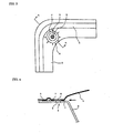
- FIG. 3 is a partially enlarged view of a steam releasing seal part of the container
- FIG. 4 is a view showing a state of a cross-section taken along a line A-A in FIG. 3 .
- a packaging container 1 for a microwave oven comprises a container body 3 having a flange part 2 and a lid 4, and the container body 3 is filled with contents (not shown) such as sterile rice, retort food, or frozen food, and thereafter, the lid 4 is heat-sealed to the periphery of the flange part 2 to seal the container hermetically.
- contents such as sterile rice, retort food, or frozen food
- the lid 4 is heat-sealed to the periphery of the flange part 2 to seal the container hermetically.
- a steam releasing seal part 6 is provided at a position separate from the peripheral seal part 5.
- the steam releasing seal part 6 comprises an outer seal part 7 obtained by heat-sealing the flange part 2 and the lid 4 in an annular shape, a buffer part 8 made of an unsealed part provided in the outer seal part 7, and a weakened part 9 made of a through-hole formed in the flange part 2 in the buffer part 8. Further, in another corner portion of the container, the peripheral seal part 5 is formed to be narrow slightly so as to project in an angular shape in an outside direction of the container to provide a sealed part 10 for opening.
- the container 1 is taken out from the microwave oven, and the container 1 is opened from the sealed part 10 for opening provided in another corner portion, and the contents are eaten.
- a tag projecting outside of the sealed part 10 for opening may be provided on the lid 4.
- the steam releasing seal part 6 is provided at a position separate from the peripheral seal part 5 inside the peripheral seal part 5 of the flange part 2, whereby the stress generated due to the increase in an internal pressure in the container is applied to the outer peripheral part of the outer seal part 7 of the steam releasing seal part 6 during heating by a microwave oven. Consequently, the peeling of the outer seal part 7 is performed smoothly and exactly.
- the lid 4 can be prevented from peeling from the peripheral seal part 5, and the container 1 can be prevented from exploding.
- the container body 3 can be prevented from being deformed without being supplied with excess stress, so that the present invention is preferable since the container is used as a dish as it is after heating/cooking, and the contents are eaten.
- the peeling of the outer seal part 7 starts, and the internal pressure of the container 1 is maintained until the peeling reaches the buffer part 8. Therefore, the taste of the contents is enhanced through a steaming effect, and the heating/cooking time by a microwave oven can be shortened.
- the buffer part 8 made of the unsealed part is provided in the outer seal part 7 of the steam releasing seal part 6, and the weakened part 9 made of the through-hole is formed in the flange part in the buffer part 8, whereby it becomes easy to position the weakened part 9 in the steam releasing seal part 6, and the operation efficiency in the steps of filling and sealing the contents can be enhanced.
- the steam releasing seal area is selected without being influenced by the size of a through-hole, a plurality of through-holes are formed depending upon the kind of the contents, etc., whereby the range of design of the steam releasing seal part is enlarged. Further, since water vapor blows out downward from the flange part 2 at a time of opening of the steam releasing seal part 6, an accident such as the burning of a user due to water vapor can be prevented.
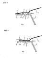
- FIG. 5 is a view showing an example of a packaging container for a microwave oven of the present invention, and shows a state of a cross-section in the vicinity of a steam releasing seal part when the container is heated by a microwave oven in the same way as in FIG. 4 .
- an annular convex part 17 is provided at a position corresponding to the outer seal part 7 of the flange part 2 of the container body 3, and the flange part 2 and the lid 4 are heat-sealed at the convex part 17, whereby the outer seal part 7 of the steam releasing seal part 6 is formed.
- the other constitutions of the packaging container 11 are the same as those of the packaging container 1 shown in FIGS.
- the buffer part 8 made of an unsealed part is provided in the outer seal part 7, and the weakened part 9 made of a through-hole is provided in the flange part 2 in the buffer part 8.
- the flat peripheral part of the flange part 2 is heat-sealed to the lid 4 along the entire periphery, whereby the peripheral seal part 5 separate from the steam releasing seal part 6 is formed.
- the annual convex part 17 can be formed in the flange part, and simultaneously, a through-hole can be formed inside thereof.
- the convex part 17 is heat-sealed, the convex part 17 is pressed by heating with a flat sealing plate having a diameter larger than the outer diameter of the convex part 17, whereby the outer seal part 7 can be formed without requiring positioning.
- FIG. 6 is a view showing another example of the packaging container for a microwave oven of the present invention, and shows a state of a cross-section in the vicinity of a steam releasing seal part when the container is heated by a microwave oven in the same way as in FIG. 4 .
- the convex part 15 is provided along the entire outer peripheral part of the flange part 2 of the container body 3, and the flange part 2 and the lid 4 are heat-sealed at the convex part 15, whereby the peripheral seal part 5 is formed.
- the other constitutions of the packaging container 21 are the same as those of the packaging container 1 shown in FIGS. 1 to 4 .
- the outer seal part 7 in which the flange part 2 and the lid 4 are heat-sealed in an annular shape, the buffer part 8 made of the unsealed part provided in the outer seal part 7, and the weakened part 9 made of a through-hole in the flange part 2 in the buffer part 8 are formed at a position separate from the peripheral seal part 5, whereby the steam releasing seal part 6 is formed.
- the convex part 15 and a through-hole to be the weakened part 9 of the steam releasing seal part 6 be formed simultaneously in the flange part when the container body 3 is molded.
- FIG. 7 is a view showing another example of the packaging container for a microwave oven of the present invention, and shows a state of a cross-section in the vicinity of a steam releasing seal part when the container is heated by a microwave oven in the same way as in FIG. 4 .
- an annular convex part 17 is provided at a position corresponding to the outer seal part 7 of the flange part 2 of the container body 3, and the flange part 2 and the lid 4 are heat-sealed at the convex part 17, whereby the outer seal part 7 of the steam releasing seal part 6 is formed.
- the convex part 15 is provided along the entire outer peripheral part of the flange part 2 of the container body 3, and the flange part 2 and the lid 4 are heat-sealed at the convex part 15, whereby the peripheral seal part 5 is formed.
- the convex part 15 and the annular convex part 17 be formed in the flange part, and simultaneously, a through-hole to be the weakened part 9 be formed inside the annular convex part 17.
- FIG. 8 is a view showing another example of the packaging container for a microwave oven of the present invention, and shows a state of a cross-section in the vicinity of a steam releasing seal part when the container is heated by a microwave oven in the same way as in FIG. 4 .
- the packaging container 41 in order to form the peripheral seal part 5 in the packaging container 31 shown in FIG. 7 , the height of the convex part 15 provided along the entire outer peripheral part of the flange part 2 of the container body 3 is set to be larger than that of the convex part 17 provided so as to form the outer seal part 7 of the steam releasing seal part 6.
- the other constitutions of the packaging container 41 are the same as those of the packaging container 31 shown in FIG. 7 .
- FIG. 9 is a view showing another example of the packaging container for a microwave oven of the present invention, which is an partially enlarged view of the steam releasing seal part of the container.
- a slit-shaped through-hole is provided in the flange part 2 in the buffer part 8 of the steam releasing seal part 6, whereby the weakened part 9 is formed in the packaging container 1 shown in FIGS. 1 to 4 .
- the other constitutions of the packaging container 51 are the same as those of the packaging container 1 shown in FIGS. 1 to 4 .
- FIG. 10 is a view showing another example of the packaging container for a microwave oven of the present invention, which is an partially enlarged view of the steam releasing seal part of the container.
- the packaging container 61 three through-holes are provided in the flange part 2 in the buffer part 8 of the steam releasing seal part 6, whereby the weakened part 9 is formed in the packaging container 1 shown in FIGS. 1 to 4 .
- the other constitutions of the packaging container 61 are the same as those of the packaging container 1 shown in FIGS. 1 to 4 .
- the shape of the packaging container can be appropriately modified.
- the shape of the packaging container is modified to a cylindrical shape, etc., and at least two steam releasing seal parts are provided, etc.
- the weakened part of the steam releasing seal part may be formed by providing a through-hole in the lid instead of the flange part, or by providing through holes both in the flange part and the lid.
- the packaging container body and the lid can be manufactured by a common method. For example, as a forming method of the container body, vacuum forming, pressure forming, vacuum pressure forming, or injection molding may be used. It is needless to say that the size of the packaging container may be set arbitrarily.
- FIG. 11 is a schematic view showing the apparatus 101 used for an improved process for manufacturing a packaging container for a microwave oven of the present invention.
- FIG. 12 is a schematic view showing the apparatus 201 used in a conventional process for manufacturing a packaging container.
- a multi-layered sheet is previously manufactured by extrusion molding, and thereafter, a rolled multi-layered sheet 102 is attached to a pressure/vacuum forming machine 101 shown in FIG. 11 to be unwound. Then, the sheet is softened or melted by a heater 103 and sent to a forming station 104. The heated sheet is pushed into a die 106 with a plug 105, and the die 106 is closed. After that, the sheet is brought into contact with the die 106 by vacuum or air pressure to be cool-solidified, thereby manufacturing a container 11 shown in FIG. 5 .
- the heated sheet is sandwiched with a pressure tool from above and below to form a part of a flange of the container 11 into an annular step shape, whereby the convex part 17 corresponding to the outer seal part 7 of the steam releasing seal part 6 is formed.
- a steam releasing hole 9 is opened in the vicinity of the center of the stepped part with a punch incorporated in the pressure tool.
- the flange outer peripheral part is trimmed off with a band-shaped blade tool incorporated into the position facing the die to cut the container 11 from the sheet, and the container 11 is transported by another apparatus.
- the processing of the steam releasing hole 9 and the trimming of the flange outer peripheral part may be performed simultaneously without forming an annular step in the step of forming as in the container 1 shown in FIGS. 1 to 4 .
- Only the formation of the convex part and the processing of the steam releasing hole by the formation of an annular step may be performed simultaneously in the step of forming a container, and the flange outer peripheral part may be trimmed off in another step.
- the packaging container for a microwave oven is manufactured by the above-mentioned process, whereby the displacement between the convex part 17 corresponding to the outer seal part 7 of the steam releasing seal part 6, the steam releasing hole 9, and the container outer peripheral part can be minimized. Consequently, the container is filled with contents and the lid is heat-sealed hermitically, and thereafter, the steam releasing seal part 6 opens smoothly at heating/cooking by a microwave oven, whereby steam is released.
- the punching by the punch 207 and the trimming of the flange outer peripheral part by a trimming apparatus 208 are performed separately after the container is formed in a forming station 204.
- each of the containers has a different pitch due to the difference in a shrinking state of the plastic sheet during the formation of the container, and the position of the steam releasing hole 9 varies, with a result that a sealing defect, abnormal releasing of steam, and the like occur.
- the container outer peripheral size also varies, so that the seal position varies when the container is filled with contents and sealed, and similar trouble may occur.
- the above-mentioned problems of prior art are solved, and a packaging container for a microwave oven can be obtained, in which the displacement of the steam releasing seal part 6 provided in the flange part is eliminated to prevent seal leakage, and the steam releasing seal part 6 opens spontaneously and stably at heating/cooking by a microwave oven.
- a square container (flange width: 8 mm in a linear portion, 17 mm of maximum width in a corner portion) with a flange having the shape shown in FIG. 5 with a container outer size of 156 mm x 133 mm and a height of 29 mm (inner capacity: about 340 ml) was formed by an ordinary vacuum/pressure forming machine.
- the annular convex part 17 with an outer diameter of 8 mm, an inner diameter of 4 mm, and a height of 0.5 mm to be the outer seal part 7 of the steam releasing seal part 6 was formed into a step by a pressure tool during formation of the container.
- a through-hole with a diameter of 2 mm to be a weakened part 9 was also formed at the center of the steam releasing seal part 6 by a punch.
- a laminate constituting a lid was formed by dry lamination in the following procedure, using a biaxially oriented polyester film (outer layer) with a thickness of 12 ⁇ m, a biaxially oriented nylon film (intermediate layer) with a thickness of 15 ⁇ m, and a polypropylene-based film (inner layer) made of an ethylene/propylene-based complex material with a thickness of 50 ⁇ m, with a polyurethane-based adhesive placed between the respective resin layers.
- an adhesive was applied to an outer layer material with a gravure roll or the like, and a solvent was evaporated and dried in a dry oven at a temperature of 80 to 100°C.
- An adhesive layer in an adhesive state and an intermediate layer material were attached, and crimped by heated metal roll and rubber roll, and thereafter, the resultant is passed through a cooling metal roll to be wound up.
- the inner layer material was attached to the laminate and cut into a desired size to constitute a lid 4.
- the above-mentioned container was filled with 200 g of sterile rice, and thereafter, the lid 4 was heat-sealed to the flange part 2 of the container to seal hermetically, whereby the peripheral seal part 5 with a seal width of 3 mm and the steam releasing seal part 6 separated from the peripheral seal part 5 was formed.
- the steam releasing seal part 6 has the buffer part 8 made of an unsealed part with a diameter of 4 mm and the weakened part 9 made of a through-hole with a diameter of 2 mm provided at the center of the flange part in the buffer part 8, inside the annular outer seal part 7 with an outer diameter of 8 mm and a seal width of 2 mm.
- the peripheral seal part 5 is set to be slightly narrow to provide an angular portion projecting outward of the container, whereby the sealed part 10 for opening was formed.
- the packaging container shown in FIG. 1 was manufactured in the same way as in Example 1, except that the steam releasing seal part 6 was formed in the flat flange part 2 without forming the annular convex part 17 to be the outer seal part 7 of the steam releasing seal part 6 in the flange part 2 in the corner portion of the container, and the packaging container was filled with 200 g of sterile rice and sealed hermitically in the same way.
- a packaging container was manufactured in the same way as in Example 2, except that the steam releasing seal part was not provided in Example 2, and the packaging container was filled with 200 g of sterile rice and sealed hermetically in the same way.
- Table 1 shows the results obtained by heating/cooking each set of 10 packaging containers filled with sterile rice and sealed hermetically obtained in the above respective examples in a 600w microwave oven. Table 1 also shows the number of damaged packaging containers obtained by dropping each set of 10 packaging containers in an inverted manner from the height of 80 cm at 5°C and checking the presence/absence of damages. Regarding these containers, the seal strength (average value) measured from inside of the container of the peripheral seal part 5 was 10.5 N/15 mm in any of the containers, and the opening strength (average value) measured from outside of the sealed part 10 for opening was 15.0 N/cup in any of the containers.
- the steam releasing seal part retracts gradually with the increase in an internal pressure by heating with a microwave oven, whereby steam was released very smoothly and exactly. At this time, the deformation of a container was suppressed to be small. Further, even in the drop test, the sealed part was not damaged. Particularly, in the packaging container of Example 1 in which the steam releasing seal part was formed into a step, because there was no displacement between the steam releasing seal part and the steam releasing hole, steam was released very stably. Further, it was found that there was little danger when a steam releasing hole is placed in the flange part of the container because steam is released downward from the container.
- the sealing performance can be maintained until the steam is released, so that the taste of rice is enhanced through a steaming effect.
- the packaging container of Comparative Example 1 in which the steam releasing seal part is not provided, steam is released from various positions by heating with a microwave oven, so that steam blows out explosively due to a large peeling area, and a steaming effect is decreased.
- a square container (flange width: 8 mm in a linear portion, 17 mm of maximum width in a corner portion) with a flange having the shape shown in FIG 5 with a container outer size of 156 mm x 133 mm and a height of 29 mm (inner capacity: about 340 ml) was formed by an ordinary vacuum/pressure forming machine shown in FIG. 11 .
- the annular convex part 17 with an outer diameter of 8 mm, an inner diameter of 4 mm, and a height of 0.2 mm to be the outer seal part 7 of the steam releasing seal part 6 was formed into a step by a pressure tool, and simultaneously, the steam releasing hole 9 with a diameter of 2.5 mm was formed at the center of the annular convex part 17 by a punch. Further, simultaneously, the flange outer peripheral part was trimmed with a band-shaped blade tool.
- a laminate constituting a lid was formed by dry lamination in the following procedure, using a biaxially oriented polyester film (outer layer) with a thickness of 12 ⁇ m, a biaxially oriented nylon film (intermediate layer) with a thickness of 15 ⁇ m, and a polypropylene-based film (inner layer) made of an ethylene/propylene-based complex material with a thickness of 50 ⁇ m, with a polyurethane-based adhesive placed between the respective resin layers.
- an adhesive was applied to an outer layer material with a gravure roll or the like, and a solvent was evaporated and dried in a dry oven at a temperature of 80 to 100°C.
- An adhesive layer in an adhesive state and an intermediate layer material were attached, and crimped by heated metal roll and rubber roll, and thereafter, the resultant is passed through a cooling metal roll to be wound up.
- the inner layer material was attached to the laminate and cut into a desired size to constitute a lid 4.
- the above-mentioned container was filled with 200 g of sterile rice, and thereafter, the lid 4 was heat-sealed to the flange part 2 of the container to seal hermetically, whereby the peripheral seal part 5 with a seal width of 2 mm and the steam releasing seal part 6 separated from the peripheral seal part 5 was formed.
- the steam releasing seal part 6 has the weakened part 9 made of a through-hole with a diameter of 2.5 mm provided at the center of the flange part in the buffer part 8 made of an unsealed part with a diameter of 4 mm, inside the annular outer seal part 7 with an outer diameter of 8 mm and a seal width of 2 mm.
- the peripheral seal part 5 is set to be slightly narrow to provide an angular portion projecting outward of the container, whereby the sealed part 10 for opening was formed.
- Example 3 a square container with a flange having the shape shown in FIGS. 1 to 4 was formed, in which the steam releasing seal part 6 was formed as the flat flange part 2, without forming the annular convex part 17 to be the outer seal part 7 of the steam releasing seal part 6 in the flange part 2 in the corner portion of the container.
- a packaging container was manufactured and filled with 200 g of sterile rice and sealed hermetically similarly.
- a packaging container shown in FIGS. 1 to 4 was manufactured in the same way as in Example 4, except that the formation of the steam releasing hole 9 with a diameter of 2.5 mm at the center of the steam releasing seal part 6 and the trimming of the flange outer peripheral part by a band-shaped blade tool were performed separately in Example 4, and filled with 200 g of sterile rice and sealed hermetically similarly.
- Table 2 shows the results obtained by heating/cooking each set of 10 packaging containers filled with sterile rice and sealed hermetically obtained in Examples 3 and 4 and Reference Example in a 600w microwave oven. Table 2 also shows the number of damaged packaging containers obtained by dropping each set of 20 packaging containers in an inverted manner from the height of 80 cm at 5°C and checking the presence/absence of damages. Regarding these containers, the seal strength (average value) measured from inside of the container of the peripheral seal part 5 was 12 N/15 mm in any of the containers, and the opening strength (average value) measured from outside of the sealed part 10 for opening was 17 N/cup in any of the containers.
- the packaging container of the present invention obtained by forming the steam releasing hole and trimming the container outer peripheral part simultaneously, the steam releasing seal part retracted gradually with the increase in an internal pressure by heating with a microwave oven, whereby the steam was released very smoothly and exactly. At this time, the deformation of the container was suppressed to be small. Further, the sealed part was not damaged even in the drop test. Particularly, in the packaging container of Example 3 in which the steam releasing seal part was formed into a step, because there is no displacement between the steam releasing seal part and the steam releasing hole, the steam was released very stably.
- the sealing performance can be maintained until the steam was released, so that the taste of rice was enhanced through a steaming effect.
- the packaging container of Reference Example in which each of the formation of the convex part by forming an annular step, the formation of the steam releasing hole, and the trimming of the container outer peripheral part was performed separately, the displacement between the steam hole and the seal was large in some cases, and the steam was released from the steam releasing hole by heating with a microwave oven and simultaneously, the steam was also released from the positions other than the steam releasing hole in some cases. No damages were found in the drop test.
Landscapes
- Engineering & Computer Science (AREA)
- Mechanical Engineering (AREA)
- Life Sciences & Earth Sciences (AREA)
- Food Science & Technology (AREA)
- Package Specialized In Special Use (AREA)
- Packages (AREA)
Claims (6)
- Verpackungsbehälter (11, 31, 41) für einen Mikrowellenofen, der durch das Dichten eines Deckels (4) unter Wärme an einem Rand eines Flanschelements (2) eines Behälterkörpers (3), der aus einem synthetischen Harz hergestellt ist, entlang eines Randdichtelements (5) hermetisch abgedichtet ist, mit zumindest einem Dampffreigabedichtelement (6), das ein geschwächtes Element (9) innerhalb des Randdichtelements (5) des Flanschelements (2) an einer Position getrennt von dem Randdichtelement (5) aufweist, wobei das geschwächte Element (9) aus einem in dem Flanschelement ausgebildeten Durchgangsloch hergestellt ist,
dadurch gekennzeichnet, dass
das Dampffreigabedichtelement (6), das in dem Flanschelement (2) bereitgestellt ist, ein äußeres Dichtelement (7) und ein ungedichtetes inneres Pufferelement (8) angrenzend an das äußere Dichtelement (7) aufweist, wobei das Durchgangsloch in dem Pufferelement (8) ausgebildet ist, und dadurch, dass
ein konvexes Element (17) an einer Position entsprechend dem äußeren Dichtelement (7) des Dampffreigabedichtelements (6) des Flanschelements (2) bereitgestellt ist, und das äußere Dichtelement (7) des Dampffreigabedichtelements (6) durch das Dichten des konvexen Elements (17) unter Wärme an den Deckel (4) ausgebildet ist. - Verpackungsbehälter (11, 31, 41) für einen Mikrowellenofen nach Anspruch 1, wobei ein Durchgangsloch in dem Deckel (4) des Pufferelements (8) des Dampffreigabedichtelements (6) ausgebildet ist.
- Verpackungsbehälter (11, 31, 41) für einen Mikrowellenofen nach Anspruch 1 oder 2, wobei ein Behälterkörper (3), der aus einem synthetischen Harz hergestellt ist, ein viereckiger Behälter ist, und das Dampffreigabedichtelement (6) in einem Eckabschnitt des Behälters bereitgestellt ist.
- Verpackungsbehälter (11, 31, 41) für einen Mikrowellenofen nach einem der Ansprüche 1 bis 3, wobei ein konvexes Element (15) entlang einem gesamten äußeren Umfangselement des Flanschelements (2) bereitgestellt ist, und der Deckel (4) an das konvexe Element (15) unter Wärme gedichtet ist, um ein Umfangsdichtelement (5) auszubilden.
- Verfahren zum Herstellen des Verpackungsbehälter (11, 31, 41) für einen Mikrowellenofen nach Anspruch 1 bis 4, mit:Gleichzeitig Ausbilden des konvexen Elements (15, 17) und des Durchgangslochs (9) als ein geschwächtes Element, die beide in dem Flanschelement (2) bereitgestellt sind, wenn der Körper (3) des Verpackungsbehälters durch das Verarbeiten einer Plastikfolie hergestellt wird, wobei das äußere Rand-Flanschelement (2) in einem getrennten Schritt abgeschnitten wird.
- Verpackungsbehälter (11, 31, 41) für einen Mikrowellenofen nach Anspruch 1 bis 4, mit:Gleichzeitig Abschneiden des äußeren Randflanschelements (2) von einer Plastikfolie und Ausbilden des konvexen Elements (15, 17) und des Durchgangslochs (9) als dem geschwächten Element, die beide in dem Flanschelement (2) bereitgestellt sind, wenn der Körper des Verpackungsbehälters (3) durch das Verarbeiten der Plastikfolie hergestellt wird.
Applications Claiming Priority (2)
| Application Number | Priority Date | Filing Date | Title |
|---|---|---|---|
| JP2006102938A JP4876679B2 (ja) | 2005-04-05 | 2006-04-04 | 電子レンジ用包装容器、及びその製造方法 |
| PCT/JP2006/319421 WO2007113930A1 (ja) | 2006-04-04 | 2006-09-29 | 電子レンジ用包装容器、及びその製造方法 |
Publications (4)
| Publication Number | Publication Date |
|---|---|
| EP2003071A2 EP2003071A2 (de) | 2008-12-17 |
| EP2003071A9 EP2003071A9 (de) | 2009-04-15 |
| EP2003071A4 EP2003071A4 (de) | 2010-05-19 |
| EP2003071B1 true EP2003071B1 (de) | 2011-11-16 |
Family
ID=38563203
Family Applications (1)
| Application Number | Title | Priority Date | Filing Date |
|---|---|---|---|
| EP06810827A Expired - Fee Related EP2003071B1 (de) | 2006-04-04 | 2006-09-29 | Verpackungsbehälter für mikrowellenofen und verfahren zu dessen herstellung |
Country Status (5)
| Country | Link |
|---|---|
| US (1) | US8245869B2 (de) |
| EP (1) | EP2003071B1 (de) |
| KR (1) | KR20080109902A (de) |
| CN (1) | CN101415621B (de) |
| WO (1) | WO2007113930A1 (de) |
Families Citing this family (11)
| Publication number | Priority date | Publication date | Assignee | Title |
|---|---|---|---|---|
| ES2415904T3 (es) * | 2009-10-13 | 2013-07-29 | Mondi Ag | Lámina de sello desprendible para crear una válvula |
| US9126734B2 (en) * | 2011-01-31 | 2015-09-08 | Ultraperf Technologies Inc. | Self venting steam valve for flexible packaging bags and pouches used in cooking of foods |
| WO2013142602A1 (en) | 2012-03-20 | 2013-09-26 | Berry Plastics Corporation | Package |
| US9145251B2 (en) | 2012-10-26 | 2015-09-29 | Berry Plastics Corporation | Package |
| US9809360B2 (en) * | 2014-07-23 | 2017-11-07 | Berry Plastics Corporation | Package with peelable closure |
| US10717585B2 (en) | 2014-09-30 | 2020-07-21 | Kyoraku Co., Ltd. | Container for microwave oven |
| US10532872B2 (en) | 2014-12-08 | 2020-01-14 | Berry Plastics Corporation | Package |
| KR101536268B1 (ko) * | 2015-01-22 | 2015-07-13 | 정희국 | 음식물 조리용 용기의 함몰 방지구조 |
| WO2018181616A1 (ja) * | 2017-03-29 | 2018-10-04 | 大日本印刷株式会社 | 容器及び容器の製造方法 |
| CN112601704B (zh) * | 2018-08-28 | 2023-04-04 | 大日本印刷株式会社 | 带盖容器 |
| US20220214047A1 (en) * | 2021-01-06 | 2022-07-07 | Bsh Home Appliances Corporation | Household cooking appliance including a non-welded oven cavity having a seal allowing pyrolytic cleaning |
Family Cites Families (18)
| Publication number | Priority date | Publication date | Assignee | Title |
|---|---|---|---|---|
| US3937396A (en) | 1974-01-18 | 1976-02-10 | Schneider William S | Valve for vented package |
| JPH0825583B2 (ja) | 1986-03-27 | 1996-03-13 | ハウス食品株式会社 | 加熱調理用密封容器 |
| JPH01107585A (ja) | 1987-10-21 | 1989-04-25 | Yaskawa Electric Mfg Co Ltd | 磁気抵抗効果素子 |
| JPH0615881Y2 (ja) * | 1988-01-13 | 1994-04-27 | 東洋製罐株式会社 | 易開封性加熱用密封容器 |
| JPH0360239A (ja) | 1989-07-28 | 1991-03-15 | Toshiba Corp | ブリッジ装置 |
| JPH0360239U (de) * | 1989-10-16 | 1991-06-13 | ||
| US5176314A (en) * | 1989-12-25 | 1993-01-05 | Sumitomo Bakelite Company Limited | Easily openable sealed container |
| US5039001A (en) * | 1990-06-18 | 1991-08-13 | Kraft General Foods, Inc. | Microwavable package and process |
| FR2698082B1 (fr) * | 1992-11-13 | 1994-12-23 | Mat Metallique Elec Const | Récipient étanche au gaz. |
| JP4124287B2 (ja) | 1997-12-12 | 2008-07-23 | 大日本印刷株式会社 | 密封容器 |
| JP4139483B2 (ja) | 1998-06-12 | 2008-08-27 | 大日本印刷株式会社 | 包装体 |
| JP3056026U (ja) | 1998-06-30 | 1999-02-02 | 株式会社尚山堂 | 電子レンジ用容器 |
| JP4843875B2 (ja) * | 2001-03-16 | 2011-12-21 | 大日本印刷株式会社 | 易開封性蓋材およびその製造方法 |
| CN1278909C (zh) * | 2001-11-20 | 2006-10-11 | 立花容器株式会社 | 包装体及包装容器 |
| JP3914137B2 (ja) | 2001-11-20 | 2007-05-16 | 立花容器株式会社 | 包装体及びその製造方法 |
| US6847022B2 (en) * | 2003-01-18 | 2005-01-25 | Steamway Franchise Sales, Inc. | Microwave cooking device with improved venting configuration |
| JP4569249B2 (ja) * | 2003-11-28 | 2010-10-27 | 東洋製罐株式会社 | 電子レンジ用包装容器 |
| JP2005187079A (ja) * | 2005-03-04 | 2005-07-14 | Toyo Seikan Kaisha Ltd | 電子レンジ用包装袋及び該電子レンジ用包装袋に内容物を充填した包装体の製造方法 |
-
2006
- 2006-09-29 EP EP06810827A patent/EP2003071B1/de not_active Expired - Fee Related
- 2006-09-29 WO PCT/JP2006/319421 patent/WO2007113930A1/ja active Application Filing
- 2006-09-29 US US12/296,176 patent/US8245869B2/en active Active
- 2006-09-29 KR KR1020087026923A patent/KR20080109902A/ko not_active Application Discontinuation
- 2006-09-29 CN CN2006800541025A patent/CN101415621B/zh active Active
Also Published As
| Publication number | Publication date |
|---|---|
| KR20080109902A (ko) | 2008-12-17 |
| EP2003071A4 (de) | 2010-05-19 |
| CN101415621A (zh) | 2009-04-22 |
| WO2007113930A1 (ja) | 2007-10-11 |
| EP2003071A2 (de) | 2008-12-17 |
| CN101415621B (zh) | 2011-08-31 |
| EP2003071A9 (de) | 2009-04-15 |
| US20090110784A1 (en) | 2009-04-30 |
| US8245869B2 (en) | 2012-08-21 |
Similar Documents
| Publication | Publication Date | Title |
|---|---|---|
| EP2019049B1 (de) | Verpackungs-korpus zum kochen in einem mikrowellenofen | |
| EP2003071B1 (de) | Verpackungsbehälter für mikrowellenofen und verfahren zu dessen herstellung | |
| JP4924613B2 (ja) | 電子レンジ調理用包装体 | |
| JP4539266B2 (ja) | 電子レンジ調理用包装体 | |
| JP5050648B2 (ja) | 電子レンジ調理用包装容器 | |
| JP5327506B2 (ja) | 電子レンジ調理用包装体 | |
| AU2004270547B2 (en) | Packaging bag for microwave oven | |
| JP4876679B2 (ja) | 電子レンジ用包装容器、及びその製造方法 | |
| JP5223516B2 (ja) | 電子レンジ調理用包装体 | |
| US8829400B2 (en) | Packaging container for cooking by electronic oven | |
| JP2005035567A (ja) | 電子レンジ対応包装容器 | |
| JP2005035568A (ja) | 電子レンジ対応包装容器 | |
| JPH10296845A (ja) | 脱酸素性多層容器の製造方法 | |
| JP2007062834A (ja) | 電子レンジ用容器 | |
| JP2005035564A (ja) | 電子レンジ対応包装容器 | |
| JP2007084104A (ja) | 電子レンジ用容器 | |
| JP2005035563A (ja) | 電子レンジ対応包装容器 | |
| JP2008074463A (ja) | プラスチック容器用蓋材 | |
| JP2006347602A (ja) | 加熱調理時に立体化可能な電子レンジ用平袋 |
Legal Events
| Date | Code | Title | Description |
|---|---|---|---|
| PUAI | Public reference made under article 153(3) epc to a published international application that has entered the european phase |
Free format text: ORIGINAL CODE: 0009012 |
|
| 17P | Request for examination filed |
Effective date: 20081002 |
|
| AK | Designated contracting states |
Kind code of ref document: A2 Designated state(s): DE FR GB IT |
|
| PUAB | Information related to the publication of an a document modified or deleted |
Free format text: ORIGINAL CODE: 0009199EPPU |
|
| RBV | Designated contracting states (corrected) |
Designated state(s): DE FR GB IT |
|
| A4 | Supplementary search report drawn up and despatched |
Effective date: 20100419 |
|
| GRAP | Despatch of communication of intention to grant a patent |
Free format text: ORIGINAL CODE: EPIDOSNIGR1 |
|
| RIC1 | Information provided on ipc code assigned before grant |
Ipc: B65D 1/26 20060101ALI20110301BHEP Ipc: B65D 81/34 20060101AFI20110301BHEP |
|
| GRAS | Grant fee paid |
Free format text: ORIGINAL CODE: EPIDOSNIGR3 |
|
| GRAA | (expected) grant |
Free format text: ORIGINAL CODE: 0009210 |
|
| DAX | Request for extension of the european patent (deleted) | ||
| AK | Designated contracting states |
Kind code of ref document: B1 Designated state(s): DE FR GB IT |
|
| REG | Reference to a national code |
Ref country code: GB Ref legal event code: FG4D |
|
| REG | Reference to a national code |
Ref country code: DE Ref legal event code: R096 Ref document number: 602006025920 Country of ref document: DE Effective date: 20120119 |
|
| PLBE | No opposition filed within time limit |
Free format text: ORIGINAL CODE: 0009261 |
|
| STAA | Information on the status of an ep patent application or granted ep patent |
Free format text: STATUS: NO OPPOSITION FILED WITHIN TIME LIMIT |
|
| 26N | No opposition filed |
Effective date: 20120817 |
|
| REG | Reference to a national code |
Ref country code: DE Ref legal event code: R097 Ref document number: 602006025920 Country of ref document: DE Effective date: 20120817 |
|
| REG | Reference to a national code |
Ref country code: FR Ref legal event code: PLFP Year of fee payment: 11 |
|
| REG | Reference to a national code |
Ref country code: FR Ref legal event code: PLFP Year of fee payment: 12 |
|
| REG | Reference to a national code |
Ref country code: FR Ref legal event code: PLFP Year of fee payment: 13 |
|
| PGFP | Annual fee paid to national office [announced via postgrant information from national office to epo] |
Ref country code: FR Payment date: 20190926 Year of fee payment: 14 Ref country code: IT Payment date: 20190925 Year of fee payment: 14 Ref country code: DE Payment date: 20190918 Year of fee payment: 14 |
|
| PGFP | Annual fee paid to national office [announced via postgrant information from national office to epo] |
Ref country code: GB Payment date: 20190925 Year of fee payment: 14 |
|
| REG | Reference to a national code |
Ref country code: DE Ref legal event code: R119 Ref document number: 602006025920 Country of ref document: DE |
|
| GBPC | Gb: european patent ceased through non-payment of renewal fee |
Effective date: 20200929 |
|
| PG25 | Lapsed in a contracting state [announced via postgrant information from national office to epo] |
Ref country code: DE Free format text: LAPSE BECAUSE OF NON-PAYMENT OF DUE FEES Effective date: 20210401 Ref country code: FR Free format text: LAPSE BECAUSE OF NON-PAYMENT OF DUE FEES Effective date: 20200930 |
|
| PG25 | Lapsed in a contracting state [announced via postgrant information from national office to epo] |
Ref country code: GB Free format text: LAPSE BECAUSE OF NON-PAYMENT OF DUE FEES Effective date: 20200929 |
|
| PG25 | Lapsed in a contracting state [announced via postgrant information from national office to epo] |
Ref country code: IT Free format text: LAPSE BECAUSE OF NON-PAYMENT OF DUE FEES Effective date: 20200929 |