EP2001711B1 - Steuergerät zur bordnetzspannungswelligkeit- robusten regelung des elektrischen stroms eines regelmagnetventils sowie zugehöriges verfahren - Google Patents
Steuergerät zur bordnetzspannungswelligkeit- robusten regelung des elektrischen stroms eines regelmagnetventils sowie zugehöriges verfahren Download PDFInfo
- Publication number
- EP2001711B1 EP2001711B1 EP07704581A EP07704581A EP2001711B1 EP 2001711 B1 EP2001711 B1 EP 2001711B1 EP 07704581 A EP07704581 A EP 07704581A EP 07704581 A EP07704581 A EP 07704581A EP 2001711 B1 EP2001711 B1 EP 2001711B1
- Authority
- EP
- European Patent Office
- Prior art keywords
- filter
- current
- control unit
- motor vehicle
- setpoint value
- Prior art date
- Legal status (The legal status is an assumption and is not a legal conclusion. Google has not performed a legal analysis and makes no representation as to the accuracy of the status listed.)
- Ceased
Links
Images
Classifications
-
- B—PERFORMING OPERATIONS; TRANSPORTING
- B60—VEHICLES IN GENERAL
- B60R—VEHICLES, VEHICLE FITTINGS, OR VEHICLE PARTS, NOT OTHERWISE PROVIDED FOR
- B60R16/00—Electric or fluid circuits specially adapted for vehicles and not otherwise provided for; Arrangement of elements of electric or fluid circuits specially adapted for vehicles and not otherwise provided for
- B60R16/02—Electric or fluid circuits specially adapted for vehicles and not otherwise provided for; Arrangement of elements of electric or fluid circuits specially adapted for vehicles and not otherwise provided for electric constitutive elements
- B60R16/03—Electric or fluid circuits specially adapted for vehicles and not otherwise provided for; Arrangement of elements of electric or fluid circuits specially adapted for vehicles and not otherwise provided for electric constitutive elements for supply of electrical power to vehicle subsystems or for
-
- B—PERFORMING OPERATIONS; TRANSPORTING
- B60—VEHICLES IN GENERAL
- B60W—CONJOINT CONTROL OF VEHICLE SUB-UNITS OF DIFFERENT TYPE OR DIFFERENT FUNCTION; CONTROL SYSTEMS SPECIALLY ADAPTED FOR HYBRID VEHICLES; ROAD VEHICLE DRIVE CONTROL SYSTEMS FOR PURPOSES NOT RELATED TO THE CONTROL OF A PARTICULAR SUB-UNIT
- B60W50/00—Details of control systems for road vehicle drive control not related to the control of a particular sub-unit, e.g. process diagnostic or vehicle driver interfaces
- B60W2050/0001—Details of the control system
- B60W2050/0019—Control system elements or transfer functions
- B60W2050/0022—Gains, weighting coefficients or weighting functions
- B60W2050/0024—Variable gains
-
- F—MECHANICAL ENGINEERING; LIGHTING; HEATING; WEAPONS; BLASTING
- F16—ENGINEERING ELEMENTS AND UNITS; GENERAL MEASURES FOR PRODUCING AND MAINTAINING EFFECTIVE FUNCTIONING OF MACHINES OR INSTALLATIONS; THERMAL INSULATION IN GENERAL
- F16H—GEARING
- F16H61/00—Control functions within control units of change-speed- or reversing-gearings for conveying rotary motion ; Control of exclusively fluid gearing, friction gearing, gearings with endless flexible members or other particular types of gearing
- F16H61/02—Control functions within control units of change-speed- or reversing-gearings for conveying rotary motion ; Control of exclusively fluid gearing, friction gearing, gearings with endless flexible members or other particular types of gearing characterised by the signals used
- F16H61/0202—Control functions within control units of change-speed- or reversing-gearings for conveying rotary motion ; Control of exclusively fluid gearing, friction gearing, gearings with endless flexible members or other particular types of gearing characterised by the signals used the signals being electric
- F16H61/0251—Elements specially adapted for electric control units, e.g. valves for converting electrical signals to fluid signals
- F16H2061/0258—Proportional solenoid valve
Definitions
- the invention is based on the object to provide for improved adjustment of the electrical current of a control solenoid valve for a motor vehicle hydraulic device, a motor vehicle control unit with a digital or discrete control loop, which is largely robust to electrical system ripples and at the same time a sufficiently high dynamic response to fast Balancing of intended jumps in the setpoint current profile of the control solenoid valve has.
- FIGS. 1 with 3 each provided with the same reference numerals.
- the hydraulic device HP is formed in practice by at least one clutch CL and / or by at least one hydraulic brake.
- the clutch CL or the hydraulic brake is in operative connection with a transmission TR of the motor vehicle.
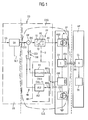
- the coil current I of the control solenoid valve CV is assigned a specific hydraulic pressure of the volume flow Q in the hydraulic device HP via its characteristic field.
- the measured, discrete actual current values CVS are then forwarded by the measuring element GM to an adaptive correction filter KFI in the feedback branch FB whose filter time can be set dynamically.
- the correction filter KFI is in the FIG. 1 symbolized by a dash-dotted outline. It is formed by a first, slower filter FI1 with a larger static filter time FT1 and a second, faster filter FI2 with a lower static filter time FT2. It therefore applies FT1> FT2.
- the first filter FI1 is seated in the feedback direction (viewed from the control loop output to the control loop input) in a first branch branch branch BR1 of the feedback path FB.
- the second filter FI2 is arranged in a second branch branch branch BR2 of the feedback path FB.
- the slower filter FI1 acts as a smoothing filter for the controlled variable CVS, which largely filters out disturbances due to electrical system voltage ripples and largely prevents them from being forwarded to the subtractor DIF.
- either the branch branch BR1 of the first filter FI1 or the branch branch BR2 of the second filter FI2 is inserted into the feedback branch FB and is there for the measured actual current values CVS effective, which act as a controlled variable of the control loop CLS.
- the switching element SW is actuated by an analysis / control unit DA.
- the analysis / control unit DA evaluates the discrete setpoint current values SS of the control loop CLS, which are fed to its forward branch FP on the input side, with regard to their level dynamics.
- the actuation of the switching device SW by the analysis / control unit DA is in the FIG. 1 indicated by a control arrow or action arrow SL1.
- the so-called D component of the manipulated variable AS of the digital controller PC can be used as the control parameter for the filter time of the individual correction filter KFI. This is in the FIG. 1 indicated by a dot-dashed arrow D between the controller PC and the adaptive correction filter KFI.
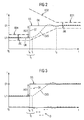
- the larger the differential component F D the greater the actual current value CVS (r) of the current control cycle r becomes the less the previous actual current value CVS (r-1) from the previous control cycle r-1 is taken into account.
Landscapes
- Engineering & Computer Science (AREA)
- Mechanical Engineering (AREA)
- Feedback Control In General (AREA)
- Magnetically Actuated Valves (AREA)
- Braking Systems And Boosters (AREA)
- Control Of Transmission Device (AREA)
Applications Claiming Priority (2)
| Application Number | Priority Date | Filing Date | Title |
|---|---|---|---|
| DE102006014352A DE102006014352B3 (de) | 2006-03-28 | 2006-03-28 | Steuergerät zur Bordnetzspannungswelligkeit-robusten Regelung des elektrischen Stroms eines Regelmagnetventils sowie zugehöriges Verfahren |
| PCT/EP2007/051446 WO2007110273A1 (de) | 2006-03-28 | 2007-02-14 | Steuergerät zur bordnetzspannungswelligkeit- robusten regelung des elektrischen stroms eines regelmagnetventils sowie zugehöriges verfahren |
Publications (2)
| Publication Number | Publication Date |
|---|---|
| EP2001711A1 EP2001711A1 (de) | 2008-12-17 |
| EP2001711B1 true EP2001711B1 (de) | 2009-11-04 |
Family
ID=37913122
Family Applications (1)
| Application Number | Title | Priority Date | Filing Date |
|---|---|---|---|
| EP07704581A Ceased EP2001711B1 (de) | 2006-03-28 | 2007-02-14 | Steuergerät zur bordnetzspannungswelligkeit- robusten regelung des elektrischen stroms eines regelmagnetventils sowie zugehöriges verfahren |
Country Status (5)
| Country | Link |
|---|---|
| US (1) | US7596442B2 (https=) |
| EP (1) | EP2001711B1 (https=) |
| JP (1) | JP5096454B2 (https=) |
| DE (2) | DE102006014352B3 (https=) |
| WO (1) | WO2007110273A1 (https=) |
Cited By (1)
| Publication number | Priority date | Publication date | Assignee | Title |
|---|---|---|---|---|
| DE102011089093B4 (de) | 2011-12-20 | 2021-08-12 | Zf Friedrichshafen Ag | Verfahren zum Betreiben eines Antriebsstrangs eines Kraftfahrzeugs |
Families Citing this family (16)
| Publication number | Priority date | Publication date | Assignee | Title |
|---|---|---|---|---|
| DE102006024708B4 (de) * | 2006-05-26 | 2009-08-13 | Continental Automotive Gmbh | Kraftfahrzeug-Steuergerät zur Druckregelung des Volumenstroms einer Kraftfahrzeug-Hydraulikvorrichtung sowie zugehöriges Verfahren zur Druckregelung |
| DE102007032178B3 (de) * | 2007-07-10 | 2008-12-11 | Continental Automotive Gmbh | Kraftfahrzeug-Kontrollvorrichtung und zugehöriges Verfahren zur Regelung des elektrischen Stroms eines Aktuators |
| JP5126023B2 (ja) * | 2008-11-26 | 2013-01-23 | トヨタ自動車株式会社 | 内燃機関装置、それを搭載した車両および内燃機関装置の制御方法 |
| US8154238B2 (en) * | 2009-03-06 | 2012-04-10 | Seagate Technology Llc | Accurate and versatile back EMF sensor |
| DE102010000101B4 (de) * | 2010-01-18 | 2014-02-13 | W.E.St. Elektronik Gmbh | Regler sowie Regelungsverfahren |
| FR2985116B1 (fr) * | 2011-12-21 | 2014-03-07 | Continental Automotive France | Dispositif de communication entre un module electronique et un capteur |
| US9067599B2 (en) * | 2013-03-05 | 2015-06-30 | GM Global Technology Operations LLC | Transmission oil pressure control during engine autostart |
| WO2016103150A1 (en) * | 2014-12-23 | 2016-06-30 | Scs Concept Italia Srl | Screwdriver test bench |
| EP3237870B1 (en) | 2014-12-23 | 2018-10-24 | SCS Concept Italia SRL | Screwdriver test bench with improved braking system |
| WO2016149505A1 (en) * | 2015-03-18 | 2016-09-22 | Automatic Switch Company | Assuring dropout of solenoid valve controlled by peek-and-hold- driver |
| JP6926482B2 (ja) * | 2017-01-13 | 2021-08-25 | オムロン株式会社 | 制御装置、制御方法、制御プログラム |
| US10727737B2 (en) * | 2017-09-08 | 2020-07-28 | Woodward, Inc. | System and method for using solenoid flyback to provide a low voltage solenoid driver power supply |
| DE102018207950A1 (de) * | 2018-05-22 | 2019-11-28 | Bayerische Motoren Werke Aktiengesellschaft | Verfahren zur Verarbeitung von Daten im Zusammenhang mit einem Fahrzeug, Decodierverfahren, Codier- und Decodierverfahren, System, Computerprogramm und Computerprogrammprodukt |
| KR102650304B1 (ko) * | 2019-05-08 | 2024-03-21 | 제네럴 일렉트릭 컴퍼니 | 하이브리드 재생 가능 발전 제어 |
| DE102023107498B3 (de) | 2023-03-24 | 2024-07-11 | Samson Aktiengesellschaft | Verfahren und Vorrichtung zum Unterdrücken von Rauschen in einem Ansteuersignal für einen Regelkreis eines Feldgeräts zum Regulieren von Fluiden in einer prozesstechnischen Anlage |
| CN116522739B (zh) * | 2023-06-29 | 2023-09-26 | 南昌科晨电力试验研究有限公司 | 一种基于数据分析的变压器短路冲击管控方法及系统 |
Family Cites Families (10)
| Publication number | Priority date | Publication date | Assignee | Title |
|---|---|---|---|---|
| US4355274A (en) * | 1980-09-08 | 1982-10-19 | Bourbeau Frank J | Load responsive control system for constant speed induction motor |
| JP3017635B2 (ja) * | 1994-02-17 | 2000-03-13 | トヨタ自動車株式会社 | 電流制御型電磁弁の制御装置 |
| DE19644611C1 (de) * | 1996-10-26 | 1998-04-23 | Bosch Gmbh Robert | Verfahren und Vorrichtung zur Regelung eines Stroms |
| JP3423876B2 (ja) * | 1997-12-25 | 2003-07-07 | 株式会社日立ユニシアオートモティブ | ソレノイド駆動装置 |
| JPH11219204A (ja) * | 1998-01-30 | 1999-08-10 | Yamatake Corp | 定値制御装置 |
| DE19937053A1 (de) * | 1998-08-17 | 2000-02-24 | Daimler Chrysler Ag | Verfahren und Vorrichtung für ein Ventil |
| JP2001290504A (ja) * | 2000-04-11 | 2001-10-19 | Yaskawa Electric Corp | 制御装置 |
| DE50213374D1 (de) * | 2001-02-02 | 2009-05-07 | Continental Automotive Gmbh | s Kraftfahrzeuggetriebes und elektro-hydraulische Steuerung für ein Kraftfahrzeuggetriebe |
| US7133268B2 (en) * | 2003-12-01 | 2006-11-07 | Texas Instruments Incorporated | Current control via a variable voltage snubbing network |
| US7053719B2 (en) * | 2004-03-11 | 2006-05-30 | Agilent Technologies, Inc. | Controlling a voltage controlled oscillator in a bang-bang phase locked loop |
-
2006
- 2006-03-28 DE DE102006014352A patent/DE102006014352B3/de not_active Expired - Fee Related
-
2007
- 2007-02-14 EP EP07704581A patent/EP2001711B1/de not_active Ceased
- 2007-02-14 JP JP2009501978A patent/JP5096454B2/ja not_active Expired - Fee Related
- 2007-02-14 DE DE502007001913T patent/DE502007001913D1/de active Active
- 2007-02-14 US US12/295,020 patent/US7596442B2/en active Active
- 2007-02-14 WO PCT/EP2007/051446 patent/WO2007110273A1/de not_active Ceased
Cited By (1)
| Publication number | Priority date | Publication date | Assignee | Title |
|---|---|---|---|---|
| DE102011089093B4 (de) | 2011-12-20 | 2021-08-12 | Zf Friedrichshafen Ag | Verfahren zum Betreiben eines Antriebsstrangs eines Kraftfahrzeugs |
Also Published As
| Publication number | Publication date |
|---|---|
| US20090138130A1 (en) | 2009-05-28 |
| WO2007110273A1 (de) | 2007-10-04 |
| US7596442B2 (en) | 2009-09-29 |
| DE502007001913D1 (de) | 2009-12-17 |
| EP2001711A1 (de) | 2008-12-17 |
| JP5096454B2 (ja) | 2012-12-12 |
| DE102006014352B3 (de) | 2007-05-03 |
| JP2009531753A (ja) | 2009-09-03 |
Similar Documents
| Publication | Publication Date | Title |
|---|---|---|
| EP2001711B1 (de) | Steuergerät zur bordnetzspannungswelligkeit- robusten regelung des elektrischen stroms eines regelmagnetventils sowie zugehöriges verfahren | |
| EP2176718B1 (de) | Kraftfahrzeug-kontrollvorrichtung und zugehöriges verfahren zur regelung des elektrischen stroms eines aktuators | |
| EP0444098B1 (de) | Verfahren zur regelung einer kupplung | |
| DE19727358B4 (de) | Druckmittelanlage sowie ein Verfahren zu deren Verwendung | |
| DE69802882T2 (de) | Überbrückungssteuerrungsvorrichtung eines Drehmomentwandlers | |
| EP0837479B1 (de) | Elektromagnettreiberschaltung | |
| EP3156651A1 (de) | Druckerhöhungsvorrichtung | |
| DE102019204402A1 (de) | Bestimmung eines Steuerstroms für ein Stetigventil | |
| DE69231984T2 (de) | Steuerung für den geregelten Eingriff einer flüssigkeitsbetriebenen Drehmomentübertragungseinrichtung | |
| EP0651182A2 (de) | Verfahren zum Steuern einer die Drehzahldifferenz einer Kupplung eines Kraftfahrzeuges bestimmenden Stellgrösse | |
| DE10304711B4 (de) | Verfahren zur Steuerung eines Elektromagnetventils, insbesondere für ein Automatikgetriebe eines Kraftfahrzeugs | |
| EP4259496A1 (de) | Verfahren zur abschätzung eines reibungskoeffizienten sowie verfahren zur bremssteuerung und bremssteuerungsvorrichtung für ein schienenfahrzeug | |
| DE102006012657A1 (de) | Steuergerät mit einem Regler zur Regelung des elektrischen Spulenstroms eines Regelmagnetventils | |
| DE102017223143A1 (de) | Verfahren zum Betreiben einer elektrohydraulischen Steuervorrichtung sowie elektrohydraulische Steuervorrichtung | |
| EP0894294B1 (de) | Verfahren zur stromregelung | |
| DE4025847A1 (de) | System zur regelung eines stellwerks in einem kraftfahrzeug | |
| DE19930965A1 (de) | Verfahren zum Betätigen eines Stromreglers für ein Stellglied sowie Stromregler | |
| DE2854929A1 (de) | Schaltungsanordnung zur unterdrueckung von stoersignalen in einem antiblockiersystem | |
| EP2030095B1 (de) | Kraftfahrzeug-steuergerät zur druckregelung des volumenstroms einer kraftfahrzeug-hydraulikvorrichtung sowie zugehöriges verfahren zur druckregelung | |
| DE10230828B4 (de) | Verfahren und Vorrichtung zur Regelung der Ausgangsgröße einer Antriebseinheit eines Fahrzeugs | |
| DE19612893B4 (de) | Steuerungsvorrichtung für ein automatisches Stufenwechselgetriebe | |
| DE19727944A1 (de) | Verfahren und Vorrichtung zur Steuerung eines Verbrauchers | |
| DE102007062173A1 (de) | Verfahren zum Betreiben einer Brennkraftmaschine und Steuer- oder Regelrichtung für eine Brennkraftmaschine | |
| DE10260838A1 (de) | Verfahren und Vorrichtung zur Steuerung einer Kupplung innerhalb eines Kraftfahrzeugtriebstrangs | |
| EP4132822B1 (de) | Verfahren und vorrichtung zum ansteuern eines fluid-magnetventils |
Legal Events
| Date | Code | Title | Description |
|---|---|---|---|
| PUAI | Public reference made under article 153(3) epc to a published international application that has entered the european phase |
Free format text: ORIGINAL CODE: 0009012 |
|
| 17P | Request for examination filed |
Effective date: 20081028 |
|
| AK | Designated contracting states |
Kind code of ref document: A1 Designated state(s): DE FR IT |
|
| RBV | Designated contracting states (corrected) |
Designated state(s): DE FR IT |
|
| GRAP | Despatch of communication of intention to grant a patent |
Free format text: ORIGINAL CODE: EPIDOSNIGR1 |
|
| DAX | Request for extension of the european patent (deleted) | ||
| GRAS | Grant fee paid |
Free format text: ORIGINAL CODE: EPIDOSNIGR3 |
|
| GRAA | (expected) grant |
Free format text: ORIGINAL CODE: 0009210 |
|
| AK | Designated contracting states |
Kind code of ref document: B1 Designated state(s): DE FR IT |
|
| REF | Corresponds to: |
Ref document number: 502007001913 Country of ref document: DE Date of ref document: 20091217 Kind code of ref document: P |
|
| PLBE | No opposition filed within time limit |
Free format text: ORIGINAL CODE: 0009261 |
|
| STAA | Information on the status of an ep patent application or granted ep patent |
Free format text: STATUS: NO OPPOSITION FILED WITHIN TIME LIMIT |
|
| 26N | No opposition filed |
Effective date: 20100805 |
|
| PG25 | Lapsed in a contracting state [announced via postgrant information from national office to epo] |
Ref country code: IT Free format text: LAPSE BECAUSE OF FAILURE TO SUBMIT A TRANSLATION OF THE DESCRIPTION OR TO PAY THE FEE WITHIN THE PRESCRIBED TIME-LIMIT Effective date: 20091104 |
|
| REG | Reference to a national code |
Ref country code: FR Ref legal event code: PLFP Year of fee payment: 10 |
|
| REG | Reference to a national code |
Ref country code: FR Ref legal event code: PLFP Year of fee payment: 11 |
|
| REG | Reference to a national code |
Ref country code: FR Ref legal event code: PLFP Year of fee payment: 12 |
|
| REG | Reference to a national code |
Ref country code: DE Ref legal event code: R084 Ref document number: 502007001913 Country of ref document: DE |
|
| REG | Reference to a national code |
Ref country code: DE Ref legal event code: R081 Ref document number: 502007001913 Country of ref document: DE Owner name: VITESCO TECHNOLOGIES GMBH, DE Free format text: FORMER OWNER: CONTINENTAL AUTOMOTIVE GMBH, 30165 HANNOVER, DE |
|
| PGFP | Annual fee paid to national office [announced via postgrant information from national office to epo] |
Ref country code: FR Payment date: 20210224 Year of fee payment: 15 |
|
| REG | Reference to a national code |
Ref country code: DE Ref legal event code: R081 Ref document number: 502007001913 Country of ref document: DE Owner name: VITESCO TECHNOLOGIES GMBH, DE Free format text: FORMER OWNER: VITESCO TECHNOLOGIES GMBH, 30165 HANNOVER, DE |
|
| PG25 | Lapsed in a contracting state [announced via postgrant information from national office to epo] |
Ref country code: FR Free format text: LAPSE BECAUSE OF NON-PAYMENT OF DUE FEES Effective date: 20220228 |
|
| PGFP | Annual fee paid to national office [announced via postgrant information from national office to epo] |
Ref country code: DE Payment date: 20230228 Year of fee payment: 17 |
|
| P01 | Opt-out of the competence of the unified patent court (upc) registered |
Effective date: 20230530 |
|
| REG | Reference to a national code |
Ref country code: DE Ref legal event code: R119 Ref document number: 502007001913 Country of ref document: DE |
|
| PG25 | Lapsed in a contracting state [announced via postgrant information from national office to epo] |
Ref country code: DE Free format text: LAPSE BECAUSE OF NON-PAYMENT OF DUE FEES Effective date: 20240903 |
|
| PG25 | Lapsed in a contracting state [announced via postgrant information from national office to epo] |
Ref country code: DE Free format text: LAPSE BECAUSE OF NON-PAYMENT OF DUE FEES Effective date: 20240903 |