EP2000757B1 - Refrigerating cycle apparatus - Google Patents
Refrigerating cycle apparatus Download PDFInfo
- Publication number
- EP2000757B1 EP2000757B1 EP08164858A EP08164858A EP2000757B1 EP 2000757 B1 EP2000757 B1 EP 2000757B1 EP 08164858 A EP08164858 A EP 08164858A EP 08164858 A EP08164858 A EP 08164858A EP 2000757 B1 EP2000757 B1 EP 2000757B1
- Authority
- EP
- European Patent Office
- Prior art keywords
- heat exchanger
- refrigerant
- indoor heat
- flow
- main valve
- Prior art date
- Legal status (The legal status is an assumption and is not a legal conclusion. Google has not performed a legal analysis and makes no representation as to the accuracy of the status listed.)
- Expired - Lifetime
Links
- 239000003507 refrigerant Substances 0.000 claims description 155
- 239000007788 liquid Substances 0.000 claims description 26
- 230000002093 peripheral effect Effects 0.000 claims description 4
- 238000004378 air conditioning Methods 0.000 description 59
- 229910052751 metal Inorganic materials 0.000 description 50
- 239000002184 metal Substances 0.000 description 50
- 238000010438 heat treatment Methods 0.000 description 46
- 238000001816 cooling Methods 0.000 description 29
- 239000011347 resin Substances 0.000 description 10
- 229920005989 resin Polymers 0.000 description 10
- 239000000463 material Substances 0.000 description 9
- 238000001704 evaporation Methods 0.000 description 7
- 238000000465 moulding Methods 0.000 description 7
- 239000000843 powder Substances 0.000 description 6
- 239000002893 slag Substances 0.000 description 5
- 238000011144 upstream manufacturing Methods 0.000 description 5
- 238000010586 diagram Methods 0.000 description 4
- 230000000694 effects Effects 0.000 description 3
- 238000005192 partition Methods 0.000 description 3
- QGZKDVFQNNGYKY-UHFFFAOYSA-N Ammonia Chemical compound N QGZKDVFQNNGYKY-UHFFFAOYSA-N 0.000 description 2
- CURLTUGMZLYLDI-UHFFFAOYSA-N Carbon dioxide Chemical compound O=C=O CURLTUGMZLYLDI-UHFFFAOYSA-N 0.000 description 2
- RTZKZFJDLAIYFH-UHFFFAOYSA-N Diethyl ether Chemical compound CCOCC RTZKZFJDLAIYFH-UHFFFAOYSA-N 0.000 description 2
- VQTUBCCKSQIDNK-UHFFFAOYSA-N Isobutene Chemical compound CC(C)=C VQTUBCCKSQIDNK-UHFFFAOYSA-N 0.000 description 2
- ATUOYWHBWRKTHZ-UHFFFAOYSA-N Propane Chemical compound CCC ATUOYWHBWRKTHZ-UHFFFAOYSA-N 0.000 description 2
- 239000000956 alloy Substances 0.000 description 2
- 229910045601 alloy Inorganic materials 0.000 description 2
- 238000007664 blowing Methods 0.000 description 2
- 238000013016 damping Methods 0.000 description 2
- 238000013461 design Methods 0.000 description 2
- 239000012530 fluid Substances 0.000 description 2
- 239000011810 insulating material Substances 0.000 description 2
- 238000002844 melting Methods 0.000 description 2
- 230000008018 melting Effects 0.000 description 2
- 238000000034 method Methods 0.000 description 2
- 238000002156 mixing Methods 0.000 description 2
- 238000012545 processing Methods 0.000 description 2
- 230000001603 reducing effect Effects 0.000 description 2
- 238000005245 sintering Methods 0.000 description 2
- 238000000638 solvent extraction Methods 0.000 description 2
- 238000010792 warming Methods 0.000 description 2
- 150000004996 alkyl benzenes Chemical class 0.000 description 1
- 229910021529 ammonia Inorganic materials 0.000 description 1
- 239000001273 butane Substances 0.000 description 1
- 229910002092 carbon dioxide Inorganic materials 0.000 description 1
- 239000001569 carbon dioxide Substances 0.000 description 1
- 239000000919 ceramic Substances 0.000 description 1
- 238000004891 communication Methods 0.000 description 1
- 238000007791 dehumidification Methods 0.000 description 1
- 230000006866 deterioration Effects 0.000 description 1
- 238000009792 diffusion process Methods 0.000 description 1
- 238000009434 installation Methods 0.000 description 1
- 239000010721 machine oil Substances 0.000 description 1
- 150000002739 metals Chemical class 0.000 description 1
- IJDNQMDRQITEOD-UHFFFAOYSA-N n-butane Chemical compound CCCC IJDNQMDRQITEOD-UHFFFAOYSA-N 0.000 description 1
- OFBQJSOFQDEBGM-UHFFFAOYSA-N n-pentane Natural products CCCCC OFBQJSOFQDEBGM-UHFFFAOYSA-N 0.000 description 1
- 239000003921 oil Substances 0.000 description 1
- 239000011148 porous material Substances 0.000 description 1
- 239000001294 propane Substances 0.000 description 1
- 238000004064 recycling Methods 0.000 description 1
- 238000004781 supercooling Methods 0.000 description 1
- 238000012546 transfer Methods 0.000 description 1
- 238000004804 winding Methods 0.000 description 1
Images


Classifications
-
- F—MECHANICAL ENGINEERING; LIGHTING; HEATING; WEAPONS; BLASTING
- F25—REFRIGERATION OR COOLING; COMBINED HEATING AND REFRIGERATION SYSTEMS; HEAT PUMP SYSTEMS; MANUFACTURE OR STORAGE OF ICE; LIQUEFACTION SOLIDIFICATION OF GASES
- F25B—REFRIGERATION MACHINES, PLANTS OR SYSTEMS; COMBINED HEATING AND REFRIGERATION SYSTEMS; HEAT PUMP SYSTEMS
- F25B13/00—Compression machines, plants or systems, with reversible cycle
-
- F—MECHANICAL ENGINEERING; LIGHTING; HEATING; WEAPONS; BLASTING
- F25—REFRIGERATION OR COOLING; COMBINED HEATING AND REFRIGERATION SYSTEMS; HEAT PUMP SYSTEMS; MANUFACTURE OR STORAGE OF ICE; LIQUEFACTION SOLIDIFICATION OF GASES
- F25B—REFRIGERATION MACHINES, PLANTS OR SYSTEMS; COMBINED HEATING AND REFRIGERATION SYSTEMS; HEAT PUMP SYSTEMS
- F25B41/00—Fluid-circulation arrangements
- F25B41/30—Expansion means; Dispositions thereof
- F25B41/31—Expansion valves
- F25B41/34—Expansion valves with the valve member being actuated by electric means, e.g. by piezoelectric actuators
- F25B41/35—Expansion valves with the valve member being actuated by electric means, e.g. by piezoelectric actuators by rotary motors, e.g. by stepping motors
-
- F—MECHANICAL ENGINEERING; LIGHTING; HEATING; WEAPONS; BLASTING
- F25—REFRIGERATION OR COOLING; COMBINED HEATING AND REFRIGERATION SYSTEMS; HEAT PUMP SYSTEMS; MANUFACTURE OR STORAGE OF ICE; LIQUEFACTION SOLIDIFICATION OF GASES
- F25B—REFRIGERATION MACHINES, PLANTS OR SYSTEMS; COMBINED HEATING AND REFRIGERATION SYSTEMS; HEAT PUMP SYSTEMS
- F25B41/00—Fluid-circulation arrangements
- F25B41/30—Expansion means; Dispositions thereof
- F25B41/39—Dispositions with two or more expansion means arranged in series, i.e. multi-stage expansion, on a refrigerant line leading to the same evaporator
-
- F—MECHANICAL ENGINEERING; LIGHTING; HEATING; WEAPONS; BLASTING
- F25—REFRIGERATION OR COOLING; COMBINED HEATING AND REFRIGERATION SYSTEMS; HEAT PUMP SYSTEMS; MANUFACTURE OR STORAGE OF ICE; LIQUEFACTION SOLIDIFICATION OF GASES
- F25B—REFRIGERATION MACHINES, PLANTS OR SYSTEMS; COMBINED HEATING AND REFRIGERATION SYSTEMS; HEAT PUMP SYSTEMS
- F25B43/00—Arrangements for separating or purifying gases or liquids; Arrangements for vaporising the residuum of liquid refrigerant, e.g. by heat
- F25B43/003—Filters
-
- G—PHYSICS
- G05—CONTROLLING; REGULATING
- G05D—SYSTEMS FOR CONTROLLING OR REGULATING NON-ELECTRIC VARIABLES
- G05D7/00—Control of flow
- G05D7/06—Control of flow characterised by the use of electric means
- G05D7/0617—Control of flow characterised by the use of electric means specially adapted for fluid materials
- G05D7/0629—Control of flow characterised by the use of electric means specially adapted for fluid materials characterised by the type of regulator means
- G05D7/0635—Control of flow characterised by the use of electric means specially adapted for fluid materials characterised by the type of regulator means by action on throttling means
- G05D7/0641—Control of flow characterised by the use of electric means specially adapted for fluid materials characterised by the type of regulator means by action on throttling means using a plurality of throttling means
- G05D7/0647—Control of flow characterised by the use of electric means specially adapted for fluid materials characterised by the type of regulator means by action on throttling means using a plurality of throttling means the plurality of throttling means being arranged in series
-
- F—MECHANICAL ENGINEERING; LIGHTING; HEATING; WEAPONS; BLASTING
- F25—REFRIGERATION OR COOLING; COMBINED HEATING AND REFRIGERATION SYSTEMS; HEAT PUMP SYSTEMS; MANUFACTURE OR STORAGE OF ICE; LIQUEFACTION SOLIDIFICATION OF GASES
- F25B—REFRIGERATION MACHINES, PLANTS OR SYSTEMS; COMBINED HEATING AND REFRIGERATION SYSTEMS; HEAT PUMP SYSTEMS
- F25B2313/00—Compression machines, plants or systems with reversible cycle not otherwise provided for
- F25B2313/023—Compression machines, plants or systems with reversible cycle not otherwise provided for using multiple indoor units
- F25B2313/0234—Compression machines, plants or systems with reversible cycle not otherwise provided for using multiple indoor units in series arrangements
- F25B2313/02341—Compression machines, plants or systems with reversible cycle not otherwise provided for using multiple indoor units in series arrangements during cooling
-
- F—MECHANICAL ENGINEERING; LIGHTING; HEATING; WEAPONS; BLASTING
- F25—REFRIGERATION OR COOLING; COMBINED HEATING AND REFRIGERATION SYSTEMS; HEAT PUMP SYSTEMS; MANUFACTURE OR STORAGE OF ICE; LIQUEFACTION SOLIDIFICATION OF GASES
- F25B—REFRIGERATION MACHINES, PLANTS OR SYSTEMS; COMBINED HEATING AND REFRIGERATION SYSTEMS; HEAT PUMP SYSTEMS
- F25B2313/00—Compression machines, plants or systems with reversible cycle not otherwise provided for
- F25B2313/023—Compression machines, plants or systems with reversible cycle not otherwise provided for using multiple indoor units
- F25B2313/0234—Compression machines, plants or systems with reversible cycle not otherwise provided for using multiple indoor units in series arrangements
- F25B2313/02343—Compression machines, plants or systems with reversible cycle not otherwise provided for using multiple indoor units in series arrangements during dehumidification
-
- F—MECHANICAL ENGINEERING; LIGHTING; HEATING; WEAPONS; BLASTING
- F25—REFRIGERATION OR COOLING; COMBINED HEATING AND REFRIGERATION SYSTEMS; HEAT PUMP SYSTEMS; MANUFACTURE OR STORAGE OF ICE; LIQUEFACTION SOLIDIFICATION OF GASES
- F25B—REFRIGERATION MACHINES, PLANTS OR SYSTEMS; COMBINED HEATING AND REFRIGERATION SYSTEMS; HEAT PUMP SYSTEMS
- F25B2313/00—Compression machines, plants or systems with reversible cycle not otherwise provided for
- F25B2313/023—Compression machines, plants or systems with reversible cycle not otherwise provided for using multiple indoor units
- F25B2313/0234—Compression machines, plants or systems with reversible cycle not otherwise provided for using multiple indoor units in series arrangements
- F25B2313/02344—Compression machines, plants or systems with reversible cycle not otherwise provided for using multiple indoor units in series arrangements during heating
-
- F—MECHANICAL ENGINEERING; LIGHTING; HEATING; WEAPONS; BLASTING
- F25—REFRIGERATION OR COOLING; COMBINED HEATING AND REFRIGERATION SYSTEMS; HEAT PUMP SYSTEMS; MANUFACTURE OR STORAGE OF ICE; LIQUEFACTION SOLIDIFICATION OF GASES
- F25B—REFRIGERATION MACHINES, PLANTS OR SYSTEMS; COMBINED HEATING AND REFRIGERATION SYSTEMS; HEAT PUMP SYSTEMS
- F25B2400/00—General features or devices for refrigeration machines, plants or systems, combined heating and refrigeration systems or heat-pump systems, i.e. not limited to a particular subgroup of F25B
- F25B2400/04—Refrigeration circuit bypassing means
- F25B2400/0411—Refrigeration circuit bypassing means for the expansion valve or capillary tube
-
- F—MECHANICAL ENGINEERING; LIGHTING; HEATING; WEAPONS; BLASTING
- F25—REFRIGERATION OR COOLING; COMBINED HEATING AND REFRIGERATION SYSTEMS; HEAT PUMP SYSTEMS; MANUFACTURE OR STORAGE OF ICE; LIQUEFACTION SOLIDIFICATION OF GASES
- F25B—REFRIGERATION MACHINES, PLANTS OR SYSTEMS; COMBINED HEATING AND REFRIGERATION SYSTEMS; HEAT PUMP SYSTEMS
- F25B2500/00—Problems to be solved
- F25B2500/12—Sound
-
- F—MECHANICAL ENGINEERING; LIGHTING; HEATING; WEAPONS; BLASTING
- F25—REFRIGERATION OR COOLING; COMBINED HEATING AND REFRIGERATION SYSTEMS; HEAT PUMP SYSTEMS; MANUFACTURE OR STORAGE OF ICE; LIQUEFACTION SOLIDIFICATION OF GASES
- F25B—REFRIGERATION MACHINES, PLANTS OR SYSTEMS; COMBINED HEATING AND REFRIGERATION SYSTEMS; HEAT PUMP SYSTEMS
- F25B2500/00—Problems to be solved
- F25B2500/26—Problems to be solved characterised by the startup of the refrigeration cycle
-
- F—MECHANICAL ENGINEERING; LIGHTING; HEATING; WEAPONS; BLASTING
- F25—REFRIGERATION OR COOLING; COMBINED HEATING AND REFRIGERATION SYSTEMS; HEAT PUMP SYSTEMS; MANUFACTURE OR STORAGE OF ICE; LIQUEFACTION SOLIDIFICATION OF GASES
- F25B—REFRIGERATION MACHINES, PLANTS OR SYSTEMS; COMBINED HEATING AND REFRIGERATION SYSTEMS; HEAT PUMP SYSTEMS
- F25B2700/00—Sensing or detecting of parameters; Sensors therefor
- F25B2700/02—Humidity
-
- Y—GENERAL TAGGING OF NEW TECHNOLOGICAL DEVELOPMENTS; GENERAL TAGGING OF CROSS-SECTIONAL TECHNOLOGIES SPANNING OVER SEVERAL SECTIONS OF THE IPC; TECHNICAL SUBJECTS COVERED BY FORMER USPC CROSS-REFERENCE ART COLLECTIONS [XRACs] AND DIGESTS
- Y02—TECHNOLOGIES OR APPLICATIONS FOR MITIGATION OR ADAPTATION AGAINST CLIMATE CHANGE
- Y02B—CLIMATE CHANGE MITIGATION TECHNOLOGIES RELATED TO BUILDINGS, e.g. HOUSING, HOUSE APPLIANCES OR RELATED END-USER APPLICATIONS
- Y02B30/00—Energy efficient heating, ventilation or air conditioning [HVAC]
- Y02B30/70—Efficient control or regulation technologies, e.g. for control of refrigerant flow, motor or heating
Definitions
- the present invention relates to a refrigerating cycle apparatus that has a throttle structure suitable to control a refrigerant flow and that is suitable to control a two-phase refrigerant, and further relates to an air conditioning apparatus that improves temperature and humidity controllability in a cooling or heating operation, reduces refrigerant flow noise, and improves comfort with respect to room temperature and humidity and noise. Further, the present invention relates to a low noise throttle device or a low noise flow controller that has a simple structure and high reliability and reduces fluid flow noise.
- the invention relates to an apparatus as defined in the preamble of claim 1.
- Which an apparatus is known from JP-A-2000-346 493 .
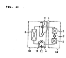
- FIG. 24 shows a refrigerant circuit diagram of a conventional air conditioning apparatus shown in Japanese Unexamined Patent Application Publication No. 11-51514
- FIG. 25 shows a sectional view of an ordinary throttle valve provided in FIG. 24 .
- numeral 1 denotes a compressor
- 2 denotes a four-way valve
- 3 denotes an outdoor heat exchanger
- 4 denotes a first flow controller
- 5 denotes a first indoor heat exchanger
- 6 denotes a second flow controller
- 7 denotes a second indoor heat exchanger
- the refrigerant ejected from the compressor 1 passes through the four-way valve 2, is condensed and liquefied in the outdoor heat exchanger 3, is reduced in pressure by a throttle device 11 because the two-way valve 12 of the first flow controller 4 is closed, is evaporated and gasified in the indoor heat exchanger 5, and returns to the compressor 1 again through the four-way valve 2.
- the refrigerant ejected from the compressor 1 passes through the four-way valve 2 inversely to the cooling operation, is condensed and liquefied in the outdoor heat exchanger 5, is reduced in pressure by the main throttle device 11 because the two-way valve 12 of the first flow controller 4 is closed, is evaporated and gasified in the outdoor heat exchanger 3, and returns to the compressor 1 again through the four-way valve 2.
- the main throttle device 11 of the first flow controller 4 is closed, and the first indoor heat exchanger 5 is operated as a condenser, that is, as a reheater and the second indoor heat exchanger 7 is operated as an evaporator by opening the 2-way valve 12 and controlling the flow amount of the refrigerant by the second flow control valve 6.
- the indoor air is heated in the first indoor heat exchanger 5, whereby it is possible to execute a dehumidifying operation in which a decrease in the room temperature is small.
- Japanese Unexamined Patent Application Publication No. 11-51514 discloses such an arrangement that an orifice-like throttle flow path composed of a plurality of cut grooves 31 and a valve disc 17 is disposed in the valve of a valve seat 18 of a second flow control valve 6 of FIG. 25 .
- numeral 16 denotes an electromagnetic coil for moving the valve disc 17
- 31 denotes a plurality of groove-like cut-outs cut in the opening 18 of a pipe acting as the valve seat and forming orifice-like throttle flow paths.
- This countermeasure for the refrigerant flow noise is devised to continuously flow the gas/liquid two-phase refrigerant through the plurality of orifice-like flow paths.
- this arrangement is not effective because the number of flow paths that can be disposed from processing point view is limited and the refrigerant flow noise is increased.
- an additional countermeasure of providing a noise insulating material and a damping material around the second flow controller 6 is required, so that a problem arises in that the cost is increased, and an installation performance and a cycle performance are deteriorated.
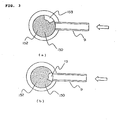
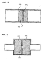
- porous members 32 acting as filters are disposed upstream and downstream of a throttle to reduce refrigerant flow noise as shown in the sectional view of FIG. 26 .
- the porous members 32 are disposed at positions separated from a throttle section, so that they cannot continuously supply a gas/liquid two-phase refrigerant effectively to the throttle section, and thus a problem arises in that refrigerant flow noise is increased.
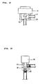
- FIG. 27 shows a sectional view of the arrangement of a flow controller used in an air conditioning apparatus disclosed in Japanese Unexamined Patent Application Publication No. 10-131 681 .
- Honeycomb pipes 37 acting as noise eliminators 36 each having holes communicating both the ends thereof are disposed upstream and downstream of a throttle to reduce refrigerant flow noise.
- FIG. 28 shows a sectional view of the honeycomb pipe.
- FIG. 1 is a refrigerant circuit diagram of an air conditioning apparatus suitable for applying a refrigerating cycle apparatus according to an embodiment of the present invention, wherein the same components as those of the conventional apparatus are denoted by the same reference numerals.
- numeral 1 denotes a compressor
- 2 denotes a flow-path switching means, for example, a 4-way valve for switching a refrigerant flow between a cooling operation and a heating operation
- 3 denotes an outdoor heat exchanger
- 4 denotes a first flow controller
- 5 denotes a first indoor heat exchanger
- 6 denotes a second flow controller
- 7 denotes a second indoor heat exchanger
- an outdoor unit 33 contains an outdoor fan 40 attached to the outdoor heat exchanger 3
- an indoor unit 34 contains an indoor fan 41 attached to the two indoor heat exchangers.
- a mixed refrigerant R410A composed of R32 mixed with R125 is used as a refrigerant of this refrigerating cycle, and alkylbenzene oil is used as ice machine oil.
- FIG. 2 is a sectional view showing the arrangement of the second flow controller of the air conditioning apparatus shown in FIG. 1 .
- numeral 9 denotes the pipe connected to the first indoor heat exchanger 5 and acts as a refrigerant flow inlet
- 13 denotes the pipe connected to the second indoor heat exchanger 7 and acts as a refrigerant flow outlet
- 150 denotes a main valve body formed into a columnar shape and rotatable in a peripheral direction about the center of a column as an axis while sliding.
- Reference numeral 151 denotes a stepping motor for driving the main valve body 150, and the main valve body 150 is adjusted by driving the stepping motor 151 in response to a command from a controller which is not shown.
- FIG. 2A is a sectional view of the main valve body 150 of the second flow controller 6 shown in FIG. 2 .
- 153 denotes a groove formed in the main valve body 150 and acting as a passing-through flow path through which a refrigerant can pass with almost no flow path resistance applied thereto.
- the main valve body 150 is formed of a porous permeable member in its entirety, and the porous permeable member is composed of sintered metal (hereinafter, referred to as a porous member 152 or a sintered metal) whose vent holes (the vent holes on the surface and inside of the porous member through which a fluid can pass) have an average diameter of 40 micrometers.
- the sintered metal is made by molding metal powder or alloy powder in a mold under pressure and sintering the resultant molded powder at a temperature lower than a melting point.
- the groove 153 formed in the main valve body has a cross sectional area larger than that of the pipe 9 connected to the second flow control valve 6 and the first indoor heat exchanger 5 and that of the pipe 13 connected to the second indoor heat exchanger 7.
- Driving the stepping motor 151 causes the groove 153 of the main valve body to move to the position of the pipe 9 connected to the second flow control valve and the first indoor heat exchanger 5 and to the position of the pipe 13 connected to the second indoor heat exchanger 7, as shown in FIG. 3 (b) , and thus the pipes can be connected thereto in a state in which almost no pressure loss is produced. Further, driving the stepping motor 151 in the same way causes the pipe 8 connected to the first indoor heat exchanger 5 to be connected to the pipe 9 connected to the second indoor heat exchanger 7 through the porous member 12 of the main valve body 10.
- solid line arrows show a refrigerant flow in a cooling operation.
- the cooling operation is divided into an ordinary cooling operation corresponding to a case in which both the air conditioning sensible heat load and the air conditioning latent heat load in a room are high at start, in summer, and the like and a dehumidifying operation corresponding to a case in which the latent heat load is large while the air conditioning sensible heat load is low as in an intermediate season, a rainy season, and the like.
- driving the stepping motor 151 of the second flow controller 6 causes the groove 153 of the main valve body 150 to be fixed to the position of the pipe 9 connected to the second flow controller and the first indoor heat exchanger 5 and to the position of the pipe 13 connected to the second indoor heat exchanger 7.
- a high temperature and high pressure vapor refrigerant ejected from the compressor 1 operating at the number of revolutions corresponding to an air conditioning load passes through the 4-way valve 2, is condensed and liquefied in the outdoor heat exchanger 3, reduced in pressure in a first flow controller 4 and made into a low pressure two-phase refrigerant, which flows into the first indoor heat exchanger 5 and is evaporated and gasified therein, passes through the second flow controller 6 without a large pressure loss, is evaporated and gasified again in the second indoor heat exchanger 7, and returns to the compressor 1 through the 4-way valve 2 again as a low pressure vapor refrigerant.
- the groove 153 of the main valve body 150 is located at the position of the pipe 9 connected to the second flow controller and the first indoor heat exchanger 5 and at the position of the pipe 13 connected to the second indoor heat exchanger 7, as shown in FIG. 3 (b) .
- the refrigerant passing through the second flow controller has almost no pressure loss, and thus the cooling capacity and efficiency are not reduced.
- the first flow controller is controlled such that the degree of superheat of the refrigerant is set to 10°C at, for example, the intake of the compressor 1.
- the heat is drawn from the inside of a room by evaporating the refrigerant in the first indoor heat exchanger 5, and the room is cooled by releasing the heat drawn from the inside of the room to the outside of the room by condensing the refrigerant in the outdoor heat exchanger 3.
- the heating amount of the air in the room heated by the first indoor heat exchanger 5 by controlling the condensing temperature of the first indoor heat exchanger by controlling the degree of opening of the first flow controller 4 and the number of revolutions of the indoor fan.
- the second flow controller 6 is controlled such that the degree of superheat of the intake refrigerant of the compressor is set to, for example, 10 °C.
- refrigerant flow noise produced when the gas/liquid two-phase refrigerant passes through the main valve body 150 can be greatly reduced because it is composed of the sintered metal.
- the gas/liquid two-phase refrigerant passes through an ordinary orifice type flow controller large refrigerant flow noise is produced. It is known that large noise is produced when the gas/liquid two-phase refrigerant flows particularly in a slag flow mode.
- the gas/liquid two-phase refrigerant and the liquid refrigerant pass through an infinite number of fine vent holes of the main valve body 150 composed of the sintered metal and are reduced in pressure. Accordingly, vapor slags and vapor bubbles are not broken. Further, since a vapor refrigerant and a liquid refrigerant simultaneously pass through the throttle section, the speed of the refrigerant is not fluctuated and the pressure thereof is not also fluctuated.
- a conventional orifice has a flow path at one position.
- the pressure of the refrigerant is reduced in the sintered metal.
- a porous member such as the sintered metal has such an effect that the fluctuation of flow speed of the refrigerant is repeated as the pressure fluctuation thereof in the interior of the porous member, and the pressure fluctuation is made constant with a part thereof being converted into thermal energy. This is generally referred to as a noise absorbing effect that is contemplated as a noise eliminating mechanism.
- the flow velocity of the refrigerant is sufficiently reduced in the porous member and made constant, no swirl is produced in the flow of the refrigerant at the outlet of the throttle section, and jet stream noise is also reduced.
- the cost can be reduced because the countermeasure required in the conventional apparatus for winding the noise insulating material and the damping material around the throttle device 6 is not necessary, and further the recycling performance of the air conditioning apparatus can be improved.
- the problem of the refrigerant flow noise due to the gas/liquid two-phase refrigerant described above is not limited to the air conditioning apparatus and is a general problem common to general refrigerating cycles such as a refrigerator, and the like, the same effect can be obtained by widely applying the throttle device to these general refrigerating cycles.
- the flow characteristics of the second flow controller 6 in the cooling/dehumidifying operation can be adjusted by adjusting the diameter of the porous member used in the main valve body 150, the length of the flow path thereof through which the refrigerant passes, and the porosity of the porous member (the volume of pores per unit volume).
- Sintered metal made by molding metal powder or alloy powder in a mold under pressure and sintering the resultant molded powder at a temperature lower than a melting point
- ceramic, foamed metal, foamed resin, and the like are used as the element of the porous member used in the main valve body.
- the main valve body 150 can be driven by the stepping motor 151, even if the main valve body 150 at the inlet of the throttle section is clogged with foreign materials in a cycle, the deterioration of performance of the main valve body 150 due to clogging can be prevented by moving a new surface thereof to the inlet by driving the motor. Further, even if the inlet portion of the porous member of the entire surface of the main valve body is clogged, the groove 153 formed in the main valve body 150 permits the function of the main valve body as the throttle device to be maintained by driving the main valve body 150 with the motor to such position that the inlet of the throttle section partly include the groove. Since the main valve has sufficient reliability as the throttle device, it is possible to provide an air conditioning apparatus having sufficient reliability.
- a preset temperature and humidity are set for the air conditioning apparatus when it is operated in order to set a temperature and humidity environment preferred by an inhabitant in a room.
- the inhabitant may directly input the respective set values of the preset temperature and humidity from a remote controller of an indoor unit.
- an optimum temperature and humidity value table which is determined for respective inhabitants who are sensitive to the heat and cold, children, elderly persons, and the like, may be stored in the remote controller of the indoor unit so that they can directly input any stored optimum values.
- the indoor unit 34 is provided with sensors for detecting the temperature and humidity of the intake air of the indoor unit to detect the room temperature and humidity.
- the difference between a preset temperature and an intake air temperature of the room and the difference between a preset humidity and an intake air humidity of the room are calculated as a temperature difference and a humidity difference, respectively, and the rotational frequency of the compressor 1, the number of revolutions of the outdoor fan, the number of revolutions of the indoor fan, the degree of throttle opening of the first flow control valve 4, and the opening/closing of the second flow control valve 6 of the air conditioning apparatus are controlled such that these differences are finally set to zero or within predetermined values.
- the air conditioning apparatus is controlled giving priority to the temperature difference over the humidity difference.
- a controller instructs the second flow control valve 6 such that the groove 153 of the main valve body 150 is located at the position of the pipe 9 connected to the second flow controller and the first indoor heat exchanger 5 and at the position of the pipe 13 connected to the second indoor heat exchanger 7, as shown in FIG. 3 (b) . Since the refrigerant passing through the second flow controller has almost no pressure loss, neither the cooling capacity nor the cooling efficiency is reduced.
- the second flow controller valve 6 is set to the open state, and the air conditioning apparatus is operated first such that the temperature difference in the room is preferentially set to zero or within the predetermined value in an ordinary cooling operation.
- the cooling capacity of the air conditioning apparatus agrees with the heat load of the room and the temperature difference is set to zero or within the predetermined value
- the humidity difference is detected.
- the operation of the air conditioning apparatus will be continued as it is.
- the second flow control valve 6 is located at such a position that the portion of the main valve body 150 other than the groove 153 is in intimate contact with the end of the pipe 9 connected to the second flow controller and the first indoor heat exchanger 5 and with the end of the pipe 13 connected to the second indoor heat exchanger 7, as shown in FIG. 3 (a) .
- the operation of the air conditioning apparatus is switched to a cooling/dehumidifying operation by throttling the second flow control valve 6.
- the heating amount of the second indoor heat exchanger 7 is controlled such that the temperature difference in the room can be maintained at zero or within the predetermined value as well as the cooling/dehumidifying amount of the first indoor heat exchanger 5 is controlled such that the humidity difference is set to zero or within the predetermined value.
- the control of the heating amount of the second indoor heat exchanger 7 is adjusted by the number of revolutions of the fan of the outdoor heat exchanger 3, the degree of opening of the first flow control valve 4, and the like. Further, the cooling/dehumidifying amount of the first indoor heat exchanger 5 is controlled by the rotational frequency of the compressor 1, the number of revolutions of the indoor fan 41 of the indoor unit 34, and the like.
- the refrigerant can stably flow through the sintered metal of the porous member 152 at a low noise level.
- the air conditioning apparatus will be described in more detail below. This description relates to a heating operation, and a refrigerant circuit constituting the air conditioning apparatus is similar to that shown in FIG. 1 , and the structure of the second flow control valve 6 is the same as that shown in FIG. 2 . Operation of the air conditioning apparatus in heating will be described.
- FIG. 1 the flow of the refrigerant in the heating is shown by broken arrows.
- the controller instructs the second flow control valve 6 such that the groove 153 of the main valve body 150 is located at the position of the pipe 9 connected to the second flow controller and the first indoor heat exchanger 5 and at the position of the pipe 13 connected to the second indoor heat exchanger 7, as shown in FIG. 3 (b) .
- the high temperature and high pressure refrigerant vapor ejected from the compressor 1 flows into the second indoor heat exchanger 7 and the first indoor heat exchanger 5 through the 4-way valve 2, exchanges heat with the indoor air and is condensed and liquefied.
- the pipe 9 is connected to the pipe 13 through a large opening area as shown in FIG. 3 (b) , the refrigerant has almost no pressure loss when it passes through the valve, and thus no decrease in the heating capacity and efficiency is caused by the pressure loss.
- the high pressure liquid refrigerant ejected from the first indoor heat exchanger 5 is reduced in pressure by the first flow controller 4 and made into a gas/liquid two-phase refrigerant, which exchanges heat with the outdoor air in the outdoor heat exchanger 3 and is evaporated.
- the low pressure vapor refrigerant ejected from the outdoor heat exchanger 3 returns to the compressor 1 again through the 4-way valve 2.
- the degree of opening of the first flow control valve 4 in the ordinary cooling operation is controlled such that the degree of superheat of the refrigerant at the outlet of the outdoor heat exchanger 3 is set to, for example, 5 °C.
- the controller instructs the second flow control valve 6 such that the main valve body 150 is located at the position where it is in intimate contact with the end of the pipe 9 connected to the second flow controller and the first indoor heat exchanger 5 and at the position where it is in intimate contact with the end of the pipe 13 connected to the second indoor heat exchanger 7, as shown in FIG. 3 (a) .
- the high temperature and pressure vapor refrigerant ejected from the compressor 1 flows into the second indoor heat exchanger 7 through the 4-way valve 2, exchanges the heat with indoor air, and is condensed (point E).
- the high pressure liquid refrigerant or the gas/liquid two-phase refrigerant flows into the second flow control valve 6.
- the refrigerant flowed into the valve flows into the first indoor heat exchanger 5 through the vent holes in the main valve body 150 composed of the sintered metal. Since the vent holes of the main valve body 150 have a diameter of about 40 ⁇ m, the refrigerant passing through the vent holes is reduced in pressure and made into an intermediate pressure gas/liquid two-phase refrigerant which flows into the first indoor heat exchanger 5 (point D).
- the saturation temperature of the refrigerant flowed into the first indoor heat exchanger 5 is equal to or less than the dew point temperature of the indoor air, and the refrigerant is evaporated by drawing the sensible heat and the latent heat of the indoor air (point C).
- the intermediate pressure gas/liquid two-phase refrigerant ejected from the first indoor heat exchanger 5 flows into the first flow control valve 4, is reduced in pressure, further flows into the outdoor heat exchanger 3, and exchanges heat with the outdoor air and is evaporated.
- the low pressure vapor refrigerant ejected from the outdoor heat exchanger 4 returns to the compressor 1 again through the 4-way valve 2.
- the heating/dehumidifying operation since the indoor air is heated in the second indoor heat exchanger 7 as well as cooled and dehumidified in the first indoor heat exchanger 5, it is possible to dehumidify the room while heating it. Further, in the heating/dehumidifying operation, it is possible to control a blowing-out air temperature in a wide range by controlling the heat exchange amount of the outdoor heat exchanger 3 by adjusting the rotational frequency of the compressor 1 and the number of revolutions of the fan of the outdoor heat exchanger 3 and by controlling the heating amount of indoor air heated by the first indoor heat exchanger 5.
- the dehumidifying amount of the indoor air dehumidified by the first indoor heat exchanger 5 by controlling the evaporating temperature of the first indoor heat exchanger 5 by adjusting the degree of opening of the first flow controller 4 and the number of revolutions of the indoor fan.
- the degree of opening of the first flow control valve 4 is controlled such that the degree of supercooling of the refrigerant at the outlet of the second indoor heat exchanger 7 is set to, for example, 10 °C.
- this apparatus employs the second flow control valve using sintered metal as the valve main body, which permits the dehumidifying operation when heating is carried out as well as can prevent the occurrence of refrigerant flow noise in the heating/dehumidifying operation, whereby a comfortable space can be realized from the standpoint of temperature and humidity environment and noise.
- the second flow control valve 6 is controlled such that the main valve body 150 is caused to come into intimate contact with the end of the pipe 9 connected to the second flow controller and the first indoor heat exchanger 5 and with the end of the pipe 13 connected to the second indoor heat exchanger 7 and throttled, as shown in FIG. 3 (a) , thereby it is possible to increase the temperature of heating blowing-out air. That is, the above heating and dehumidifying cycle is formed at the start of heating, and the evaporating temperature of the first indoor heat exchanger 5 is controlled by the second flow control valve such that it is made approximately the same as the temperature of indoor intake air.
- the evaporating temperature of the first indoor heat exchanger 5 is approximately the same as the temperature of the intake air of the room, almost no cooling and dehumidifying are carried out in the first indoor heat exchanger 5.
- the heat transfer area of the condenser in heating is made about one half that in the ordinary heating operation, and thus a condensing temperature is increased as compared with that in the ordinary heating operation, whereby the blowing-out temperature can be increased.
- no refrigerant flow noise is produced in the second flow control valve 6 and thus no problem is caused from noise point of view.
- the air conditioning apparatus carries out a high temperature air blowing out operation for a predetermined period of time, for example, five minutes at the start of heating and then shifts to the ordinary heating operation. Thereafter, switching between the ordinary heating operation and the heating/dehumidifying operation is controlled according to the temperature difference and the humidity difference of the room.
- the second flow control valve 6 is controlled such that the main valve body 150 is caused to come into intimate contact with the end of the pipe 9 connected to the second flow controller and the first indoor heat exchanger 5 and with the end of the pipe 13 connected to the second indoor heat exchanger 7 and throttled, as shown in FIG. 3 (a) ; then the compressor 1 is started.
- the evaporating temperature of the first indoor heat exchanger 5 is controlled to be equal to the intake air temperature by adjusting the number of revolutions of the fan of the outdoor heat exchanger 3, the degree of opening of the first flow control valve 4, and the like such that the cooling and dehumidifying capacity in the first indoor heat exchanger 5 is set to zero.
- the air conditioning apparatus shifts to the ordinary heating operation by setting the second flow control valve 6 to the open state, as shown in FIG. 3 (b) .
- the rotational frequency of the compressor 1, the number of revolutions of the indoor fan, and the number of revolutions of the outdoor fan are adjusted such that the temperature difference is set to zero or within a predetermined value.
- the humidity difference is detected.
- the heating/dehumidifying operation is carried out by setting the second flow control valve 6 to the throttled state, as shown in FIG. 3 (a) .
- the heating amount of the second indoor heat exchanger 7 is controlled such that the temperature difference in the room can be maintained at zero or within the predetermined value and also the cooling/ dehumidifying amount of the first indoor heat exchanger 5 is controlled such that the humidity difference is set to zero or within the predetermined value.
- the heating amount of the second indoor heat exchanger 7 is controlled by the rotational frequency of the compressor 1, the number of revolutions of the fan of the indoor unit 34, and the like. Further, the control of the cooling/dehumidifying amount of the first indoor heat exchanger 5 is adjusted by the number of revolutions of the fan of the outdoor heat exchanger 3, the degree of opening of the first flow control valve 4, and the like.
- this apparatus it is possible in this apparatus to control the temperature and humidity environment in the room to an optimum state according to the preference of an inhabitant by switching the refrigerant circuit from one to another of the heating/high temperature air blowing out operation, the ordinary heating operation, and the heating/dehumidifying operation according to the operating time and the load based on the room in the heating operation.
- FIG. 4 is a sectional view of the arrangement of the second flow controller of the air conditioning apparatus showing another example thereof
- FIG. 5 is a sectional view of the main valve body 150 of the second flow controller shown in FIG. 4 , wherein the constitutional components that are the same as or similar to those shown in FIGS. 2 and 2A are denoted by the same reference numerals, and the duplicate description thereof is omitted.
- the main valve body 150 is arranged such that the porous member 152 is assembled to a core portion 150a of resin or metal that is ordinarily used.
- Driving the stepping motor 151 in response to a command from the controller (not shown) causes the main valve body 150 to be located at the position shown in FIG. 6 (a) , whereby the pipe 9 connected to the first indoor heat exchanger 5 can be connected to the pipe 13 connected to the second indoor heat exchanger 7 with almost no pressure loss through the groove 153 of the main valve body.
- driving the stepping motor 151 in the same way causes the porous member 152 of the main valve body 150 to face the pipe 98 connected to the first indoor heat exchanger 5 and the pipe 13 connected to the second indoor heat exchanger 7 at the position of the porous member 152c, as shown in FIG. 6 (c) , whereby these pipes are connected to each other through the vent holes.
- Driving the stepping motor 151 in the same way causes the shut-off portion 150d of the main valve body 150 to face the pipe 9 connected to the first indoor heat exchanger 5 and the pipe 13 connected to the second indoor heat exchanger 7, as shown in FIG. 6 (d) , whereby the shut-off portion 150d shuts off the flow path.
- the second flow controller 6 in which no refrigerant flow noise is produced can be obtained at a less expensive material cost by molding a part of the main valve body 150 of the sintered metal as shown in this apparatus rather than molding the overall main valve body 150 of the sintered metal as shown in FIG. 2 .
- the core portion 150a prevents the groove 153 from communicating with the porous permeable member 152. Accordingly, the refrigerant does not flow into the porous permeable member 152 in the open state shown in FIG. 6 (a) , and thus the durability of the porous permeable member 152 can be improved.
- the compressor 1 when the compressor 1 is intermittently operated such as when it is repeatedly started and stopped in a case such that the air conditioning load is smaller than the capacity of the compressor 1 of the air conditioning apparatus even if the number of revolutions thereof is minimized, the pressure in the outdoor heat exchanger 3 and the pressure in the indoor heat exchanger 5 are kept in the state during operation when the compressor is stopped by totally closing the pipes 9 and 13 by causing the shut-off portion 150d having a resin or metal surface similarly to the main valve body 150 to face the pipes as shown in FIG. 6 (d) and the starting-up performance of the compressor 1 is improved when it is started next, whereby energy saving operation can be realized.
- FIG. 7 is a sectional view of the arrangement of the second flow controller of the air conditioning apparatus showing another example of the present invention
- FIG. 8 is a sectional view of the main valve body 150 of the second flow controller showing another example of the present invention, wherein the constitutional components that are the same as or similar to those shown in FIGS. 2 and 2A are denoted by the same reference numerals, and the duplicate description thereof is omitted.
- the main valve 15 is arranged such that sintered metal is assembled to ordinarily used resin or metal so that the thickness thereof is continuously increased with respect to the center of a valve disc.
- Driving the stepping motor 151 in response to a command from the controller (not shown) causes the groove 153 of the main valve body 150 to be located at a position where a connecting flow path for connecting the pipe 9 connected to the first indoor heat exchanger 5 to the pipe 13 connected to the second indoor heat exchanger 7 is formed, as shown in FIG. 9 (a) . In this state, they can be connected to each other with almost no pressure loss.
- driving the stepping motor 151 in the same way causes the porous member 152 of the main valve body 150 to be located at the position where the pipe 9 connected to the first indoor heat exchanger 5 and the pipe 13 connected to the second indoor heat exchanger 7 face the thick wall portion 152c of the porous member 152 having a small flow resistance, as shown in FIG. 9 (c) to thereby connect them through the vent holes.
- driving the stepping motor 151 causes the shut-off portion 150d of the main valve body 150 to face the pipe 9 connected to the first indoor heat exchanger 5 and the pipe 13 connected to the second indoor heat exchanger 7, as shown in FIG. 9 (d) , and thus a refrigerant flow path is shut off.
- the second flow controller 6 in which no refrigerant flow noise is produced can be obtained at a less expensive material cost by molding a part of the main valve body 150 of the sintered metal as shown in this structure rather than molding the whole main valve body 150 of the sintered metal as shown in FIG. 2A .
- the pressure difference between the first indoor heat exchanger 5 and the second indoor heat exchanger 7 can be adjusted by moving the valve disc by the stepping motor 151 of the second flow controller 6 to operate the refrigerating cycle most effectively.
- Continuously forming the sintered metal permits the main valve body 150 to be processed simply. Further, the main valve body 150 can be reduced in size because the portion where the porous member 152 directly faces the pipes 9 and 13 and the portion in the vicinity thereof can be arranged as a flow path.
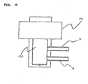
- FIG. 10 is a sectional view of the arrangement of the second flow controller of the air conditioning apparatus
- FIG. 11 is a sectional view of the main valve body 150 of the second flow controller, wherein the constitutional components that are the same as or similar to those shown in FIGS. 2 and 2A are denoted by the same reference numerals, and the duplicate description thereof is omitted.
- the core portion 150a of the main valve body 150 is composed of ordinarily used resin or metal, and three types of porous members 152d, 152e, and 152f composed of sintered metal and having vent holes with different average diameters are assembled and disposed in the core portion 150a in the order of the flow resistances thereof; the respective porous members are partitioned from each other by partitions 150b composed of the same material as that of the core portion 150a.
- Driving the stepping motor 151 in response to a command from the controller (not shown) causes the groove 153 of the main valve body 150 to be connected to the pipe 9 connected to the first indoor heat exchanger 5 and to the pipe 13 connected to the second indoor heat exchanger 7 with almost no pressure loss, as shown in FIG. 12 (a) .
- Driving the stepping motor 151 in the same way causes the porous member 152d, having a small flow resistance, of the main valve body 150 to face the pipe 9 connected to the first indoor heat exchanger 5 and the pipe 13 connected to the second indoor heat exchanger 7, as shown in FIG. 12 (b) to thereby connect them through the vent holes.
- Driving the stepping motor 151 in the same way causes the porous member 152e having an intermediate flow resistance to face the pipe 9 connected to the first indoor heat exchanger 5 and the pipe 13 connected to the second indoor heat exchanger 7, as shown in FIG. 12 (c) to thereby connect them through the vent holes.
- Driving the stepping motor 151 in the same way causes the porous member 152c having a large flow resistance to face the pipe 9 connected to the first indoor heat exchanger 5 and the pipe 13 connected to the second indoor heat exchanger 7, as shown in FIG. 12 (d) to thereby connect them through the vent holes.
- the second flow controller 6 in which no refrigerant flow noise is produced can be obtained with easy processing at a less expensive material cost by forming the main valve body 150 by assembling the three types of sintered metals whose vent holes have the different average diameters to the ordinarily used resin or metal at the three positions of the main valve body 150 as shown in FIG. 11 rather than molding the main valve body 150 by assembling the sintered metal to the ordinarily used resin or metal such that the thickness of the sintered metal is continuously increased with respect to the center of the valve disc as shown in FIG. 7 .
- the cross sectional areas of the flow paths of the plurality of porous members 152 can be precisely partitioned from each other by partitioning them by the partitions 150b, and thus the flow rate can be controlled precisely.
- the refrigerant can be prevented from flowing into the porous member having the small flow resistance by partitioning the porous members each having the different flow resistance by the partitions 150d as in this apparatus.
- FIG. 13 is a sectional view of the arrangement of the second flow controller 6 of the air conditioning apparatus of the present invention, wherein the constitutional components that are the same as or similar to those shown in FIG. 2 are denoted by the same reference numerals, and the duplicate description thereof is omitted.
- the main valve body 150 is composed of the ordinarily used resin or metal, and the space of the refrigerant flow path formed by the main valve body 150 and a valve seat 154 in a valve chamber is filled with the porous member 152 formed into a columnar shape.
- the sintered metal has vent holes whose average diameter is 0.5 ⁇ m to 200 ⁇ m.
- the valve seat 154 forms a communication port for causing the porous member 152 in the periphery thereof to communicate with the pipe 13 on the pipe 13 side in the valve chamber.
- Deenergizing an electromagnetic coil 155 causes the main valve body 150 to be separated from the valve seat 154, and thus the pipe 9 connected to the first indoor heat exchanger 5 can be connected to the pipe 13 connected to the second indoor heat exchanger 7 with almost no pressure loss because they are connected to each other through a large opening area, as shown in FIG. 13 (a) . Further, when the electromagnetic coil 155 is energized, the pipe 9 connected to the first indoor heat exchanger 5 and the pipe 13 connected to the second indoor heat exchanger 7 are connected to the throttle flow path of the porous member 152 of the sintered metal, which is formed by causing the main valve body 150 to come into intimate contact with the valve seat 154, through the vent holes of the porous member 152, as shown in FIG. 13 (b) .
- a low noise throttle device can be realized at lower cost as compared with the throttle device using the stepping motor because the main valve body 150 is driven by the electromagnetic coil 155. Since the porous member is formed into the columnar shape, it can be easily processed. Further, the durability to clogging of the porous member is greatly improved because the refrigerant inlet of the porous member can be increased in size. While the porous member is formed into the columnar shape in this embodiment, it is sufficient to form the porous member into any shape formed according to the space formed by the main valve body 150 and the valve seat 154.
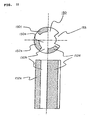
- FIG. 14 is a sectional view of the arrangement of the second flow controller 6 of the air conditioning apparatus of the present invention, wherein the constitutional components that are the same as or similar to those shown in FIG. 2 are denoted by the same reference numerals, and the duplicate description thereof is omitted.
- FIG. 15 is a detailed view of the orifices 156 used in the flow controller.
- the main valve body 150 and the valve seat 154 are formed of the ordinarily used resin or metal, and the main valve body 150 is moved in a vertical direction in the valve chamber by energizing and deenergizing the electromagnetic coil 155.
- the refrigerant flow path that reaches the pipe 13 bypassing the valve seat 154 is formed around the columnar valve seat 154 in the valve chamber formed by the main valve body 150 and the valve seat 154.
- the porous members 152 composed of the sintered metal whose vent holes have a diameter of from 100 ⁇ m to 500 ⁇ m are uniformly disposed in the refrigerant flow path so as to be approximately flush with the upper end of the valve seat 154. Further, the orifices 156 each having an inside diameter of 0.5 mm and a thickness of 1 mm are equally disposed at four positions between the porous members 152 in the flow direction of the refrigerant. The orifices 156 are sandwiched between the upper and lower porous members 152 and fitted to the side wall of the valve chamber as well as the lower porous member 152 (located downstream of the refrigerant flow) is abutted against the bottom of the valve chamber so as to be fixed at a given position.
- valve seat 154 is not abutted against the lower portion of the valve chamber (on the pipe 9 side), and a predetermined gap is formed to cause the refrigerant flow path to communicate with the pipe 13. However, since the valve seat 154 is fixed to the orifices 156 or formed integrally therewith, the above gap is held by the orifices 156 fixed in the vertical direction.
- Deenergizing the electromagnetic coil 155 causes the main valve 150 to be separated from the valve seat 154, so that the pipe 9 connected to the first indoor heat exchanger 5 can be connected to the pipe 13 connected to the second indoor heat exchanger 7 with almost no pressure loss because they are connected to each other through the large opening area that uses the inside of the valve seat 154 as a path, as shown in FIG. 14 (a) .
- the refrigerant flow path around the valve seat 154 that is formed by causing the main valve body 150 to come into close contact with the valve seat 154 is connected to the pipe 9 connected to the first indoor heat exchanger 5 and to the pipe 13 connected to the second indoor heat exchanger 7 through the vent holes of the porous members 152 composed of the sintered metal and the orifices 156, as shown in FIG. 14 (b) .
- the orifices 156 and the porous members 152 function as the throttle section together.
- the orifices 156 are in intimate contact with the porous members 152 located thereon and thereunder.
- the porous member 152 located on the upper side of the orifices 156 (upstream of the refrigerant flow) causes a gas/liquid two-phase refrigerant to pass therethrough in a mixed state and further prevents a pressure fluctuation produced by the orifices 156 from being transmitted upstream.
- the porous member 152 located on the lower side of the orifices 156 prevents the pressure fluctuation produced by a jet stream on the outlet side from being transmitted downstream, while it has no pressure drop produced by the orifices 156.
- the refrigerant flow in the refrigerating cycle is stable, and thus the air conditioning apparatus can realize a target air conditioning environment in a short time.
- the pipe 9 acting as the refrigerant inlet is connected to the side of the valve chamber and the refrigerant flows in from the side of the valve chamber through the pipe 9.
- the main valve body 150 is positioned at the center of the valve chamber in the vertical direction and acts as a diffusion member for diffusing the inflow refrigerant.
- the inflow refrigerant from the pipe 9 impinges on the main valve body 150 and is diffused thereby, which prevents the refrigerant from impinging on the opposite wall in the valve chamber and partially flowing into the porous member 152 opposite to the pipe 9 in the valve chamber so as to effectively use the refrigerant flow path.
- the gas/liquid two-phase refrigerant impinges on the wall of the valve chamber and is diffused, it is separated to the liquid and the gas on the side where the refrigerant impinges in the valve chamber and on the pipe side (the side where the diffused refrigerant flows into the porous members 152), and thus the phase state of the refrigerant flowing in the throttle section is not made uniform.
- the main valve body 150 diffuses the inflow refrigerant at the center of the valve chamber, the refrigerant flows into the porous members 152 in a more uniform phase state.
- the upper end of the valve seat 154 is approximately flush with the upper surface of the porous member 152, when the valve is opened (a state in which the main valve body 150 is moved upward and separated from the valve seat 154), the refrigerant from the pipe 9 smoothly flows into the valve seat 154. Further, the height in the valve chamber can be reduced by making the upper end of the valve seat 154 to be approximately flush with the upper surface of the porous member 152.
- the main valve body 150 When the valve is closed (a state in which the main valve body 150 is abutted against the valve seat 154), the main valve body 150 is not abutted against the porous member 152 because the peripheral corner of the main valve body 150 abutted against the valve seat 154 is chamfered. Therefore, it is not necessary for the porous members 152 to be provided with strength and durability capable of withstanding the abutment thereof against the main valve body 150. Since the valve seat 154 is integral with the orifices that are in intimate contact with the porous members 152, the positional relationship between the valve seat 154 and the porous members 152 is kept constant. Thus, the main valve body 150 is not abutted against the upper porous member 152 even if they are used for a long period of time.
- a main throttle section is composed of the orifices 156 in this structure, the diameter of the vent holes of the porous members 152 composed of the sintered metal and acting as an auxiliary throttle section can be increased, which can more improve the durability to clogging of the porous members 152. Since the valve seat 154 is molded integrally with the orifices 156, the valve seat 154 can be easily positioned.
- porous members 152 are disposed just before and behind the orifices 156, they can cause even the gas/liquid two-phase refrigerant to continuously pass therethrough, and thus refrigerant flow noise can be reduced. Further, while the embodiment shows the example in which the orifices 156 are disposed at the four positions, they may be disposed at any of one position to an infinite number of positions because the inside diameter and thickness of the orifices are designed optimally according to the flow characteristics thereof when the orifices are designed.
- FIG. 16 is a sectional view of the arrangement of the second flow controller 6 of the air conditioning apparatus showing another example, wherein the constitutional components that are the same as or similar to those shown in FIG. 2 are denoted by the same reference numerals, and the duplicate description thereof is omitted.
- the main valve body 150 and the valve seat 154 are formed of ordinarily used resin or metal.
- Porous members 152i and h are composed of the sintered metal and have vent holes whose diameter is set from 100 ⁇ m to 500 ⁇ m and a function as an auxiliary throttle section.
- the porous members 152i and 152 h are disposed in the refrigerant flow path in the valve chamber, which is formed by the main valve body 150 and the valve seat 154, and just behind the outlet side of the throttle section.
- the average diameter of the vent holes of the sintered metal is set from 100 micrometers to 500 micrometers so as to reduce the flow resistance of the refrigerant passing therethrough.
- the peripheral corner of the extreme end of the main valve body 150 is chamfered and has a groove 153 formed therearound.
- the valve seat 154 which faces the main valve body 150, is positioned lower than the abutting surface of the porous member 152h, which is contained in the valve seat 154, where it is abutted against the main valve body 150.
- the flow path is formed through the groove 153 in a state in which the main valve body 150 is abutted against the porous member 152h.
- This flow path constitutes the orifice section acting as the main throttle section because it is narrow and has a large flow path resistance.
- the pipe 9 connected to the first indoor heat exchanger 5 is connected to the pipe 13 connected to the second indoor heat exchanger 7 through the large opening area, as shown in FIG. 16 (a) , which permits the refrigerant flow path to be connected to the pipes with a pressure loss not larger than that of the porous members 152 composed of the sintered metal.
- the electromagnetic coil 155 is energized, the main valve body 150 is caused to be in intimate contact with the valve seat 154, which permits the vent holes of the porous members 152 composed of the sintered metal and the groove 153 formed in the valve seat to create the orifice section, as shown in FIG. 16 (b) .
- the pipe 9 connected to the first indoor heat exchanger 5 is connected to the pipe 13 connected to the second indoor heat exchanger 7 through the orifice section.
- the orifice 156 acts as the main throttle section in this structure, the diameter of the vent holes of the porous members 152, which are composed of the sintered metal and act as the auxiliary throttle section, can be increased, and thus the durability to clogging of the porous members 152 can be improved.
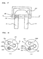
- FIG. 17 is a sectional view of the arrangement of the second flow controller of the air conditioning apparatus of the present invention. Further, FIG. 18 is a sectional view taken along the line A - A' of FIG. 17 and shows the operation of a switching flow path.
- the constitutional components that are the same as or similar to those shown in FIG. 2 are denoted by the same reference numeral, and the duplicate description thereof is omitted.
- Reference numeral 157 denotes a switching flow path driven by the electromagnetic coil or the stepping motor.
- Reference numeral 158 denotes a plurality of second flow controller outlet flow paths formed in the rotational direction of the switching flow path 157, that is, a passing through hole 158a for introducing the refrigerant to the pipe 9 without a flow resistance, and a throttle section 158b containing the porous member 152 acting as a flow resistance to introduce the refrigerant to the pipe 13 while reducing the pressure thereof.
- the pipe 9 connected to the first indoor heat exchanger 5 can be connected to the pipe 13 connected to the second indoor heat exchanger 7 with almost no pressure loss ( FIG. 18 (a) ).
- the switching flow path 157 is connected to the throttle section 158b acting as the second flow controller outlet flow path by driving the switching flow path 157 by the stepping motor in the same way, the pipe 9 connected to the first indoor heat exchanger 5 is connected to the pipe 13 connected to the second indoor heat exchanger 7 through the vent holes of the porous member 152 composed of the sintered metal, as shown in FIG. 18 (b) .
- the porous member 152 is formed into a columnar shape according to the shape of the throttle section 158b, it can be easily processed, and thus a low noise flow controller can be realized at less expensive cost. Further, since the shape of the refrigerant inlet of the porous member 152 can be easily changed, the design can be easily changed according to flow characteristics. While the porous members are described as the columnar shape in this structure, they may be formed into any shape according to the shape of the valve seat 154.
- FIG. 19 is a sectional view of the arrangement of the second flow controller 6 of the air conditioning apparatus as a further example.
- the constitutional components that are the same as or similar to those shown in FIGS. 17 and 18 are denoted by the same reference numerals, and the duplicate description thereof is omitted.
- FIG. 20 depicts sectional views similar to the A - A sectional view of FIG. 18 and showing the operation of the switching flow path.
- porous members 152e and 152f composed of the sintered metal and having the vent holes with different diameters (different flow path resistances) are assembled to the throttle sections 158b and 158c of the outlet flow paths of the second flow controller.
- the pipe 9 connected to the first indoor heat exchanger 5 can be connected to the pipe 13 connected to the second indoor heat exchanger 7 with almost no pressure loss ( FIG. 20 (a) .
- the switching flow path 157 is connected to the throttle section 158b, which has a small flow path resistance, of the second flow controller outlet flow paths by driving the switching flow path 157 by the stepping motor in the same way as shown in FIG. 18 (b)
- the pipe 9 connected to the first indoor heat exchanger 5 is connected to the pipe 13 connected to the second indoor heat exchanger 7 through the vent holes of the porous member 152 composed of the sintered metal.
- the switching flow path 157 is connected to the throttle section 158c, which has a large flow path resistance, of the second flow controller outlet flow paths by driving the switching flow path 157 by the stepping motor as shown in FIG. 18 (c)
- the pipe 9 connected to the first indoor heat exchanger 5 is connected to the pipe 13 connected to the second indoor heat exchanger 7 through the vent holes of the porous member 152 composed of the sintered metal whose flow resistance is larger than that of the throttle section 158b.
- the second flow controller outlet flow paths 158 are located at three positions, and the vent holes of the porous members disposed at the two positions thereof have different diameters, which permits the flow rate of the refrigerant to be controlled according to an air conditioning load so as to adjust the refrigerating capacity. As a result, a more comfortable dehumidifying operation can be carried out.
- the throttle section may be composed of a porous member whose vent holes have a diameter from 100 micrometers to 500 micrometers with an orifice having an inside diameter from 0.5 mm to 3 mm held in the midway of the porous member.
- FIG. 21 depicts views showing the arrangement of the second flow controller 6 of the air conditioning apparatus showing another example, wherein numeral 12 denotes a two-way valve, 159 denotes the throttle section formed in a pipe 160 acting as a bypass flow path for bypassing the 2-way valve 12.
- numeral 12 denotes a two-way valve
- 159 denotes the throttle section formed in a pipe 160 acting as a bypass flow path for bypassing the 2-way valve 12.
- FIG. 21 depicts detailed views of the throttle section 159
- FIG. 22 is a detailed view of another throttle section.
- porous members 152 denotes the porous members
- 156 denotes the orifice
- 160 denotes the pipe.
- the porous members 152 are force-fitted into the pipe 160 in the state in which the orifice 156 is sandwiched therebetween without leaving any gap.
- the porous members 152 are composed of the sintered metal having vent holes whose diameter is set from 100 micrometers to 500 micrometers and the thickness set from 1 mm to 100 mm, and the orifice 156 having an inside diameter of 1.0 mm and a thickness of 1 mm is disposed at one position between the porous members 152.
- Deenergizing the electromagnetic coil 155 causes the main valve 150 to be separated from the valve seat 154, as shown in FIG. 21 (a) , and thus the pipe 9 connected to the first indoor heat exchanger 5 can be connected to the pipe 13 connected to the second indoor heat exchanger 7 with almost no pressure loss because they are connected to each other through the large opening area. Further, energizing the electromagnetic coil 155 causes the main valve body 150 to come into intimate contact with the valve seat 154, as shown in FIG. 21 (b) , so that the pipe 9 connected to the first indoor heat exchanger 5 is connected to the pipe 13 connected to the second indoor heat exchanger 7 through the vent holes of the porous members 152 composed of the sintered metal and formed in the throttle section 159.
- the throttle device is combined with the two-way valve, the structure of the throttle section 159 is simplified, and thus a low noise throttle can be realized at low cost. Since the porous members 152 and the orifice 156 are disposed in the pipe 160 without leaving any gap therebetween, it is possible to flow the gas/liquid two-phase refrigerant into the orifice in a uniformly mixed state, which can suppress a pressure fluctuation and reduce refrigerant flow noise.
- the orifice 156 is disposed at the single position in the example, the orifice may be disposed at any of one position to an infinite number of positions and may be formed in any thickness because the inside diameter and thickness of the orifice is designed optimally according to the flow characteristics thereof when it is designed.
- R410A is used as the refrigerant of the air conditioning apparatus.
- the refrigerant R410A is an ozone-friendly HFC refrigerant suitable for the conservation of global environment. Further, since R410A has a smaller refrigerant pressure loss as compared with R22 that has been heretofore used as the refrigerant, it permits to reduce the size of the vent holes of the porous member used in the throttle section of the second flow control valve 6. Thus, a higher refrigerant flow noise reducing effect can be obtained by R410A.
- the refrigerant of the air conditioning apparatus is not limited to R410A, and R407C, R404A, and R507A that are HFC refrigerants may be used.
- R32 alone, R152a alone, a mixed refrigerant of R32/R134a, and the like as HFC refrigerants having a small global warming coefficient may be used from the view point of preventing global warming.
- HC refrigerants such as propane, butane, isobutene, etc.
- natural refrigerants such as ammonia, carbon dioxide, ether, and the like
- mixed refrigerants made by mixing them may be used.
Description
- The present invention relates to a refrigerating cycle apparatus that has a throttle structure suitable to control a refrigerant flow and that is suitable to control a two-phase refrigerant, and further relates to an air conditioning apparatus that improves temperature and humidity controllability in a cooling or heating operation, reduces refrigerant flow noise, and improves comfort with respect to room temperature and humidity and noise. Further, the present invention relates to a low noise throttle device or a low noise flow controller that has a simple structure and high reliability and reduces fluid flow noise.
- In particular, the invention relates to an apparatus as defined in the preamble of
claim 1. Which an apparatus is known fromJP-A-2000-346 493 - Conventional air conditioning apparatuses use a variable capacitance type compressor such as an inverter, and the like to cope with the fluctuations of an air conditioning load, and the rotational frequency of the compressor is controlled according to the magnitude of the air conditioning load. However, when the number of rotations of the compressor is reduced in a cooling operation, an evaporating temperature also increases, thus a problem arises in that the dehumidifying capacity of an evaporator is reduced or an evaporating temperature exceeds the dew point temperature in a room and dehumidification cannot be executed.
- The following air conditioning apparatus is devised as a means for improving the dehumidifying capacity in a cooling low capacitance operation.
FIG. 24 shows a refrigerant circuit diagram of a conventional air conditioning apparatus shown in Japanese Unexamined Patent Application Publication No.11-51514 FIG. 25 shows a sectional view of an ordinary throttle valve provided inFIG. 24 . - In the figure,
numeral 1 denotes a compressor, 2 denotes a four-way valve, 3 denotes an outdoor heat exchanger, 4 denotes a first flow controller, 5 denotes a first indoor heat exchanger, 6 denotes a second flow controller, and 7 denotes a second indoor heat exchanger, and these components are sequentially connected through pipes and constitute a refrigerating cycle. - Next, operation of the conventional air conditioning apparatus will be described below. In a cooling operation, the refrigerant ejected from the
compressor 1 passes through the four-way valve 2, is condensed and liquefied in the outdoor heat exchanger 3, is reduced in pressure by athrottle device 11 because the two-way valve 12 of thefirst flow controller 4 is closed, is evaporated and gasified in theindoor heat exchanger 5, and returns to thecompressor 1 again through the four-way valve 2. - Further, in a heating operation, the refrigerant ejected from the
compressor 1 passes through the four-way valve 2 inversely to the cooling operation, is condensed and liquefied in theoutdoor heat exchanger 5, is reduced in pressure by themain throttle device 11 because the two-way valve 12 of thefirst flow controller 4 is closed, is evaporated and gasified in the outdoor heat exchanger 3, and returns to thecompressor 1 again through the four-way valve 2. - In contrast, in a dehumidifying operation, the
main throttle device 11 of thefirst flow controller 4 is closed, and the firstindoor heat exchanger 5 is operated as a condenser, that is, as a reheater and the secondindoor heat exchanger 7 is operated as an evaporator by opening the 2-way valve 12 and controlling the flow amount of the refrigerant by the secondflow control valve 6. Thus, the indoor air is heated in the firstindoor heat exchanger 5, whereby it is possible to execute a dehumidifying operation in which a decrease in the room temperature is small. - In the conventional air conditioning apparatuses as described above, since a flow control valve having an orifice is usually used as the second flow control valve disposed in an indoor unit, large refrigerant flow noise is produced when the refrigerant passes through the orifice and the indoor environment is deteriorated thereby. In particular, since the inlet of the second flow control valve is filled with a gas/liquid two-phase refrigerant in the dehumidifying operation, a problem arises in that the refrigerant flow noise is increased.
- As a countermeasure for the refrigerant flow noise of the second flow control valve in the dehumidifying operation, Japanese Unexamined Patent Application Publication No.
11-51514 cut grooves 31 and avalve disc 17 is disposed in the valve of avalve seat 18 of a secondflow control valve 6 ofFIG. 25 . Note thatnumeral 16 denotes an electromagnetic coil for moving thevalve disc opening 18 of a pipe acting as the valve seat and forming orifice-like throttle flow paths. - This countermeasure for the refrigerant flow noise is devised to continuously flow the gas/liquid two-phase refrigerant through the plurality of orifice-like flow paths. However, there is a problem that this arrangement is not effective because the number of flow paths that can be disposed from processing point view is limited and the refrigerant flow noise is increased. As a result, an additional countermeasure of providing a noise insulating material and a damping material around the
second flow controller 6 is required, so that a problem arises in that the cost is increased, and an installation performance and a cycle performance are deteriorated. - In contrast, in a flow controller used in an air conditioning apparatus shown in Japanese Unexamined Patent Application Publication No.
7-146 032 porous members 32 acting as filters are disposed upstream and downstream of a throttle to reduce refrigerant flow noise as shown in the sectional view ofFIG. 26 . However, theporous members 32 are disposed at positions separated from a throttle section, so that they cannot continuously supply a gas/liquid two-phase refrigerant effectively to the throttle section, and thus a problem arises in that refrigerant flow noise is increased. - Further,
FIG. 27 shows a sectional view of the arrangement of a flow controller used in an air conditioning apparatus disclosed in Japanese Unexamined Patent Application Publication No.10-131 681 pipes 37 acting asnoise eliminators 36 each having holes communicating both the ends thereof are disposed upstream and downstream of a throttle to reduce refrigerant flow noise.FIG. 28 shows a sectional view of the honeycomb pipe. - Since the area of each hole formed in the pipe is too small for a refrigerant to pass therethrough, a problem arises in that the hole is liable to be clogged by foreign materials flowing in a refrigerating cycle and the performance of the flow controller is lowered by a drop of the flow amount of the refrigerant. Further, another problem arises in that the refrigerant cannot be flowed without the occurrence of pressure loss because no bypass is formed for the throttle section.
- An object of the present invention, which was made to solve the above problems, is to provide a refrigerating cycle apparatus using a throttle device and a flow controller that can greatly reduce refrigerant flow noise and are not clogged by foreign materials in a cycle. Another object of the present invention is to provide a low noise and reliable refrigerating cycle apparatus.
- The apparatus according to the invention is disclosed in
claim 1. Advantageous specific embodiments are specified in the subclaims. -
- FIG. 1
- is a refrigerant circuit diagram of an air conditioning apparatus suitable for applying a refrigerating cycle apparatus of the present invention;
- FIG. 2
- is a sectional view showing the arrangement of a throttle device for an apparatus according to
FIG. 1 ; - FIG. 2A
- is a detailed view of a main valve body of the throttle device ;
- FIG. 3
- depicts views showing operation of the throttle device ;
- FIG. 4
- is a sectional view of the arrangement of the throttle device ;
- FIG. 5
- is a detailed view of a main valve body of the throttle device ;
- FIG. 6
- depicts sectional views of the arrangement of the throttle device ;
- FIG. 7
- is a sectional view of the arrangement of the throttle device ;
- FIG. 8
- is a sectional view of the arrangement of the throttle device ;
- FIG. 9
- depicts sectional views of the arrangement of the throttle device ;
- FIG. 10
- is a sectional view of the arrangement of the throttle device ;
- FIG. 11
- is a sectional view of the arrangement of the throttle device ;
- FIG. 12
- depicts sectional views of the arrangement of the throttle device ;
- FIG. 13
- depicts sectional views of the arrangement of the throttle device according to an embodiment of the apparatus of the present invention;
- FIG. 14
- depicts sectional views of the arrangement of the throttle device according to an embodiment of the apparatus of the present invention;
- FIG. 15
- is a detailed view of an orifice used in the throttle device according to an embodiment of the apparatus of the present invention;
- FIG. 16
- depicts sectional views of the arrangement of another throttle device ;
- FIG. 17
- is a sectional view of the arrangement of another throttle device ;
- FIG. 18
- depicts views showing operation of another throttle device ;
- FIG. 19
- is a sectional view of the arrangement of another throttle device ;
- FIG. 20
- depicts views showing operation of another throttle device ;
- FIG. 21
- depicts sectional views of the arrangement of another throttle device ;
- FIG. 22
- is a detailed view of another throttle device ;
- FIG. 23
- is a detailed view of another throttle device ;
- FIG. 24
- is a refrigerant circuit diagram showing a conventional air conditioning apparatus;
- FIG. 25
- is a sectional view of the arrangement of a conventional throttle device.
- FIG. 26
- is a sectional view showing the arrangement of another example of the conventional throttle device;
- FIG. 27
- is a sectional view showing the arrangement of another example of the conventional throttle device; and
- FIG. 28
- is a sectional view of the noise eliminating section of the throttle device shown in
FIG. 27 . -
FIG. 1 is a refrigerant circuit diagram of an air conditioning apparatus suitable for applying a refrigerating cycle apparatus according to an embodiment of the present invention, wherein the same components as those of the conventional apparatus are denoted by the same reference numerals. In the figure, numeral 1 denotes a compressor, 2 denotes a flow-path switching means, for example, a 4-way valve for switching a refrigerant flow between a cooling operation and a heating operation, 3 denotes an outdoor heat exchanger, 4 denotes a first flow controller, 5 denotes a first indoor heat exchanger, 6 denotes a second flow controller, and 7 denotes a second indoor heat exchanger, and these components are sequentially connected to each other through pipes and constitute a refrigerating cycle. - Further, an
outdoor unit 33 contains anoutdoor fan 40 attached to the outdoor heat exchanger 3, and anindoor unit 34 contains anindoor fan 41 attached to the two indoor heat exchangers. A mixed refrigerant R410A composed of R32 mixed with R125 is used as a refrigerant of this refrigerating cycle, and alkylbenzene oil is used as ice machine oil. -
FIG. 2 is a sectional view showing the arrangement of the second flow controller of the air conditioning apparatus shown inFIG. 1 . In the figure, numeral 9 denotes the pipe connected to the firstindoor heat exchanger 5 and acts as a refrigerant flow inlet, 13 denotes the pipe connected to the secondindoor heat exchanger 7 and acts as a refrigerant flow outlet, and 150 denotes a main valve body formed into a columnar shape and rotatable in a peripheral direction about the center of a column as an axis while sliding.Reference numeral 151 denotes a stepping motor for driving themain valve body 150, and themain valve body 150 is adjusted by driving the steppingmotor 151 in response to a command from a controller which is not shown. -
FIG. 2A is a sectional view of themain valve body 150 of thesecond flow controller 6 shown inFIG. 2 . In the figure, 153 denotes a groove formed in themain valve body 150 and acting as a passing-through flow path through which a refrigerant can pass with almost no flow path resistance applied thereto. Themain valve body 150 is formed of a porous permeable member in its entirety, and the porous permeable member is composed of sintered metal (hereinafter, referred to as aporous member 152 or a sintered metal) whose vent holes (the vent holes on the surface and inside of the porous member through which a fluid can pass) have an average diameter of 40 micrometers. The sintered metal is made by molding metal powder or alloy powder in a mold under pressure and sintering the resultant molded powder at a temperature lower than a melting point. - The
groove 153 formed in the main valve body has a cross sectional area larger than that of thepipe 9 connected to the secondflow control valve 6 and the firstindoor heat exchanger 5 and that of thepipe 13 connected to the secondindoor heat exchanger 7. Driving the steppingmotor 151 causes thegroove 153 of the main valve body to move to the position of thepipe 9 connected to the second flow control valve and the firstindoor heat exchanger 5 and to the position of thepipe 13 connected to the secondindoor heat exchanger 7, as shown inFIG. 3 (b) , and thus the pipes can be connected thereto in a state in which almost no pressure loss is produced. Further, driving the steppingmotor 151 in the same way causes the pipe 8 connected to the firstindoor heat exchanger 5 to be connected to thepipe 9 connected to the secondindoor heat exchanger 7 through theporous member 12 of themain valve body 10. - Next, operation of the refrigerating cycle of the air conditioning apparatus will be described.
- In
FIG. 1 , solid line arrows show a refrigerant flow in a cooling operation. The cooling operation is divided into an ordinary cooling operation corresponding to a case in which both the air conditioning sensible heat load and the air conditioning latent heat load in a room are high at start, in summer, and the like and a dehumidifying operation corresponding to a case in which the latent heat load is large while the air conditioning sensible heat load is low as in an intermediate season, a rainy season, and the like. In the ordinary cooling operation, driving the steppingmotor 151 of thesecond flow controller 6 causes thegroove 153 of themain valve body 150 to be fixed to the position of thepipe 9 connected to the second flow controller and the firstindoor heat exchanger 5 and to the position of thepipe 13 connected to the secondindoor heat exchanger 7. - At this time, a high temperature and high pressure vapor refrigerant ejected from the
compressor 1 operating at the number of revolutions corresponding to an air conditioning load passes through the 4-way valve 2, is condensed and liquefied in the outdoor heat exchanger 3, reduced in pressure in afirst flow controller 4 and made into a low pressure two-phase refrigerant, which flows into the firstindoor heat exchanger 5 and is evaporated and gasified therein, passes through thesecond flow controller 6 without a large pressure loss, is evaporated and gasified again in the secondindoor heat exchanger 7, and returns to thecompressor 1 through the 4-way valve 2 again as a low pressure vapor refrigerant. - In the second flow controller, the
groove 153 of themain valve body 150 is located at the position of thepipe 9 connected to the second flow controller and the firstindoor heat exchanger 5 and at the position of thepipe 13 connected to the secondindoor heat exchanger 7, as shown inFIG. 3 (b) . Thus, the refrigerant passing through the second flow controller has almost no pressure loss, and thus the cooling capacity and efficiency are not reduced. - Further, the first flow controller is controlled such that the degree of superheat of the refrigerant is set to 10°C at, for example, the intake of the
compressor 1. In this refrigerating cycle, the heat is drawn from the inside of a room by evaporating the refrigerant in the firstindoor heat exchanger 5, and the room is cooled by releasing the heat drawn from the inside of the room to the outside of the room by condensing the refrigerant in the outdoor heat exchanger 3. - Note that, in the dehumidifying operation, it is possible to control a blowing-out air temperature in a wide range by adjusting the rotational frequency of the
compressor 1 and the number of revolutions of the fan of the outdoor heat exchanger 3 to control its amount of heat exchange and by controlling the heating amount of the air in the room heated by the firstindoor heat exchanger 5. - Further, it is also possible to control the heating amount of the air in the room heated by the first
indoor heat exchanger 5 by controlling the condensing temperature of the first indoor heat exchanger by controlling the degree of opening of thefirst flow controller 4 and the number of revolutions of the indoor fan. Further, thesecond flow controller 6 is controlled such that the degree of superheat of the intake refrigerant of the compressor is set to, for example, 10 °C. - In this embodiment, refrigerant flow noise produced when the gas/liquid two-phase refrigerant passes through the
main valve body 150 can be greatly reduced because it is composed of the sintered metal. When the gas/liquid two-phase refrigerant passes through an ordinary orifice type flow controller, large refrigerant flow noise is produced. It is known that large noise is produced when the gas/liquid two-phase refrigerant flows particularly in a slag flow mode. - This is because that when the flow mode of the gas/liquid two-phase refrigerant is the slag flow as described above, a vapor refrigerant intermittently flows in a flow direction, and when the vapor slags or vapor bubbles having a size larger than the flow path of a throttle section, the vapor slags or vapor bubbles upstream of the flow path of the throttle section are broken and vibrated and that since a vapor refrigerant and a liquid refrigerant alternately pass through the throttle section, the speed of the refrigerant is fast when the vapor refrigerant passes and slow when the liquid refrigerant passes, and the pressure of the refrigerant is also fluctuated thereby. Further, in a conventional
second flow controller 6, since outlet flow paths are disposed at one to four positions at the outlet of thecontroller 6, the refrigerant has a fast flow speed, and swirls are produced at the outlet portion of thecontroller 6 so that jet stream noise is increased thereat. - In the
second flow controller 6 shown inFIG. 2 , the gas/liquid two-phase refrigerant and the liquid refrigerant pass through an infinite number of fine vent holes of themain valve body 150 composed of the sintered metal and are reduced in pressure. Accordingly, vapor slags and vapor bubbles are not broken. Further, since a vapor refrigerant and a liquid refrigerant simultaneously pass through the throttle section, the speed of the refrigerant is not fluctuated and the pressure thereof is not also fluctuated. - A conventional orifice has a flow path at one position. However, since the flow paths in sintered metal are formed intricately, the pressure of the refrigerant is reduced in the sintered metal. A porous member such as the sintered metal has such an effect that the fluctuation of flow speed of the refrigerant is repeated as the pressure fluctuation thereof in the interior of the porous member, and the pressure fluctuation is made constant with a part thereof being converted into thermal energy. This is generally referred to as a noise absorbing effect that is contemplated as a noise eliminating mechanism. Further, since the flow velocity of the refrigerant is sufficiently reduced in the porous member and made constant, no swirl is produced in the flow of the refrigerant at the outlet of the throttle section, and jet stream noise is also reduced.
- As a result, the cost can be reduced because the countermeasure required in the conventional apparatus for winding the noise insulating material and the damping material around the
throttle device 6 is not necessary, and further the recycling performance of the air conditioning apparatus can be improved. Note that since the problem of the refrigerant flow noise due to the gas/liquid two-phase refrigerant described above is not limited to the air conditioning apparatus and is a general problem common to general refrigerating cycles such as a refrigerator, and the like, the same effect can be obtained by widely applying the throttle device to these general refrigerating cycles. - The flow characteristics of the
second flow controller 6 in the cooling/dehumidifying operation (the relationship between the flow amount of refrigerant and pressure loss) can be adjusted by adjusting the diameter of the porous member used in themain valve body 150, the length of the flow path thereof through which the refrigerant passes, and the porosity of the porous member (the volume of pores per unit volume). - That is, when a certain flow amount of refrigerant is flowed with a small pressure loss, it is sufficient to increase the diameter of the vent holes of the porous member (to increase the size of the element of the porous member), to decrease the length of the flow path thereof (to decrease the length of a valve main body), or to use a porous member having a large porosity.
- Inversely, when a certain flow amount of refrigerant is flowed with a large pressure loss, it is sufficient to decrease the diameter of the vent holes of the porous member (to decrease the size of the element of the porous member), to increase the length of the flow path thereof (to increase the length of the valve main body), or to use a porous member having a small porosity. The diameter of the vent holes of the porous member used in a main valve body and the shape of the valve main body are optimally designed at the time of design of equipment.
- Sintered metal (made by molding metal powder or alloy powder in a mold under pressure and sintering the resultant molded powder at a temperature lower than a melting point), ceramic, foamed metal, foamed resin, and the like are used as the element of the porous member used in the main valve body.
- Since the
main valve body 150 can be driven by the steppingmotor 151, even if themain valve body 150 at the inlet of the throttle section is clogged with foreign materials in a cycle, the deterioration of performance of themain valve body 150 due to clogging can be prevented by moving a new surface thereof to the inlet by driving the motor. Further, even if the inlet portion of the porous member of the entire surface of the main valve body is clogged, thegroove 153 formed in themain valve body 150 permits the function of the main valve body as the throttle device to be maintained by driving themain valve body 150 with the motor to such position that the inlet of the throttle section partly include the groove. Since the main valve has sufficient reliability as the throttle device, it is possible to provide an air conditioning apparatus having sufficient reliability. - Next, an operation control method of the air conditioning apparatus will be described. A preset temperature and humidity, for example, are set for the air conditioning apparatus when it is operated in order to set a temperature and humidity environment preferred by an inhabitant in a room. Note that the inhabitant may directly input the respective set values of the preset temperature and humidity from a remote controller of an indoor unit.
- Further, an optimum temperature and humidity value table, which is determined for respective inhabitants who are sensitive to the heat and cold, children, elderly persons, and the like, may be stored in the remote controller of the indoor unit so that they can directly input any stored optimum values. Further, the
indoor unit 34 is provided with sensors for detecting the temperature and humidity of the intake air of the indoor unit to detect the room temperature and humidity. - When the air conditioning apparatus is started, the difference between a preset temperature and an intake air temperature of the room and the difference between a preset humidity and an intake air humidity of the room are calculated as a temperature difference and a humidity difference, respectively, and the rotational frequency of the
compressor 1, the number of revolutions of the outdoor fan, the number of revolutions of the indoor fan, the degree of throttle opening of the firstflow control valve 4, and the opening/closing of the secondflow control valve 6 of the air conditioning apparatus are controlled such that these differences are finally set to zero or within predetermined values. At this time, when the temperature and humidity differences are controlled to zero or within the predetermined values, the air conditioning apparatus is controlled giving priority to the temperature difference over the humidity difference. - That is, when both the temperature and humidity differences are large at the start of the air conditioning apparatus, a controller instructs the second
flow control valve 6 such that thegroove 153 of themain valve body 150 is located at the position of thepipe 9 connected to the second flow controller and the firstindoor heat exchanger 5 and at the position of thepipe 13 connected to the secondindoor heat exchanger 7, as shown inFIG. 3 (b) . Since the refrigerant passing through the second flow controller has almost no pressure loss, neither the cooling capacity nor the cooling efficiency is reduced. - As described above, the second
flow controller valve 6 is set to the open state, and the air conditioning apparatus is operated first such that the temperature difference in the room is preferentially set to zero or within the predetermined value in an ordinary cooling operation. When the cooling capacity of the air conditioning apparatus agrees with the heat load of the room and the temperature difference is set to zero or within the predetermined value, the humidity difference is detected. When the humidity difference is set to zero or within the predetermined value at this time, the operation of the air conditioning apparatus will be continued as it is. - When the temperature difference is zero or within the predetermined value and the humidity difference at the time still has a large value, the second
flow control valve 6 is located at such a position that the portion of themain valve body 150 other than thegroove 153 is in intimate contact with the end of thepipe 9 connected to the second flow controller and the firstindoor heat exchanger 5 and with the end of thepipe 13 connected to the secondindoor heat exchanger 7, as shown inFIG. 3 (a) . - As described above, the operation of the air conditioning apparatus is switched to a cooling/dehumidifying operation by throttling the second
flow control valve 6. In the cooling/ dehumidifying operation, the heating amount of the secondindoor heat exchanger 7 is controlled such that the temperature difference in the room can be maintained at zero or within the predetermined value as well as the cooling/dehumidifying amount of the firstindoor heat exchanger 5 is controlled such that the humidity difference is set to zero or within the predetermined value. - The control of the heating amount of the second
indoor heat exchanger 7 is adjusted by the number of revolutions of the fan of the outdoor heat exchanger 3, the degree of opening of the firstflow control valve 4, and the like. Further, the cooling/dehumidifying amount of the firstindoor heat exchanger 5 is controlled by the rotational frequency of thecompressor 1, the number of revolutions of theindoor fan 41 of theindoor unit 34, and the like. - As described above, it is possible to control the temperature and humidity environment in a room to an optimum state according to the preference of an inhabitant by switching the refrigerant circuit between the ordinary cooling operation and the cooling/dehumidifying operation according to the load of the room in the cooling operation. Further, even if the state of phase of the refrigerant passing through the throttle device and the mixing ratio of gas and liquid in the refrigerant are changed by the change of modes such as cooling, dehumidifying, heating, and the like and the change of an air conditioning load, the refrigerant can stably flow through the sintered metal of the
porous member 152 at a low noise level. - The air conditioning apparatus will be described in more detail below. This description relates to a heating operation, and a refrigerant circuit constituting the air conditioning apparatus is similar to that shown in
FIG. 1 , and the structure of the secondflow control valve 6 is the same as that shown inFIG. 2 . Operation of the air conditioning apparatus in heating will be described. - In
FIG. 1 , the flow of the refrigerant in the heating is shown by broken arrows. In an ordinary heating operation, the controller instructs the secondflow control valve 6 such that thegroove 153 of themain valve body 150 is located at the position of thepipe 9 connected to the second flow controller and the firstindoor heat exchanger 5 and at the position of thepipe 13 connected to the secondindoor heat exchanger 7, as shown inFIG. 3 (b) . - At this time, the high temperature and high pressure refrigerant vapor ejected from the
compressor 1 flows into the secondindoor heat exchanger 7 and the firstindoor heat exchanger 5 through the 4-way valve 2, exchanges heat with the indoor air and is condensed and liquefied. Note that since thepipe 9 is connected to thepipe 13 through a large opening area as shown inFIG. 3 (b) , the refrigerant has almost no pressure loss when it passes through the valve, and thus no decrease in the heating capacity and efficiency is caused by the pressure loss. - The high pressure liquid refrigerant ejected from the first
indoor heat exchanger 5 is reduced in pressure by thefirst flow controller 4 and made into a gas/liquid two-phase refrigerant, which exchanges heat with the outdoor air in the outdoor heat exchanger 3 and is evaporated. The low pressure vapor refrigerant ejected from the outdoor heat exchanger 3 returns to thecompressor 1 again through the 4-way valve 2. The degree of opening of the firstflow control valve 4 in the ordinary cooling operation is controlled such that the degree of superheat of the refrigerant at the outlet of the outdoor heat exchanger 3 is set to, for example, 5 °C. - Next, operation of the air conditioning apparatus in heating/dehumidifying will be explained in correspondence to the alphanumeric characters shown in
FIG. 1 . In the heating/ dehumidifying operation, the controller instructs the secondflow control valve 6 such that themain valve body 150 is located at the position where it is in intimate contact with the end of thepipe 9 connected to the second flow controller and the firstindoor heat exchanger 5 and at the position where it is in intimate contact with the end of thepipe 13 connected to the secondindoor heat exchanger 7, as shown inFIG. 3 (a) . - At this time, the high temperature and pressure vapor refrigerant ejected from the
compressor 1 flows into the secondindoor heat exchanger 7 through the 4-way valve 2, exchanges the heat with indoor air, and is condensed (point E). The high pressure liquid refrigerant or the gas/liquid two-phase refrigerant flows into the secondflow control valve 6. - In the second
flow control valve 6, since themain valve body 150 is in intimate contact with the end of thepipe 9 connected to the second flow controller and the firstindoor heat exchanger 5 and with the end of thepipe 13 connected to the secondindoor heat exchanger 7, as shown inFIG. 3 (a) , the refrigerant flowed into the valve flows into the firstindoor heat exchanger 5 through the vent holes in themain valve body 150 composed of the sintered metal. Since the vent holes of themain valve body 150 have a diameter of about 40 µm, the refrigerant passing through the vent holes is reduced in pressure and made into an intermediate pressure gas/liquid two-phase refrigerant which flows into the first indoor heat exchanger 5 (point D). - The saturation temperature of the refrigerant flowed into the first
indoor heat exchanger 5 is equal to or less than the dew point temperature of the indoor air, and the refrigerant is evaporated by drawing the sensible heat and the latent heat of the indoor air (point C). The intermediate pressure gas/liquid two-phase refrigerant ejected from the firstindoor heat exchanger 5 flows into the firstflow control valve 4, is reduced in pressure, further flows into the outdoor heat exchanger 3, and exchanges heat with the outdoor air and is evaporated. The low pressure vapor refrigerant ejected from theoutdoor heat exchanger 4 returns to thecompressor 1 again through the 4-way valve 2. - In the heating/dehumidifying operation, since the indoor air is heated in the second
indoor heat exchanger 7 as well as cooled and dehumidified in the firstindoor heat exchanger 5, it is possible to dehumidify the room while heating it. Further, in the heating/dehumidifying operation, it is possible to control a blowing-out air temperature in a wide range by controlling the heat exchange amount of the outdoor heat exchanger 3 by adjusting the rotational frequency of thecompressor 1 and the number of revolutions of the fan of the outdoor heat exchanger 3 and by controlling the heating amount of indoor air heated by the firstindoor heat exchanger 5. - Further, it is also possible to control the dehumidifying amount of the indoor air dehumidified by the first
indoor heat exchanger 5 by controlling the evaporating temperature of the firstindoor heat exchanger 5 by adjusting the degree of opening of thefirst flow controller 4 and the number of revolutions of the indoor fan. The degree of opening of the firstflow control valve 4 is controlled such that the degree of supercooling of the refrigerant at the outlet of the secondindoor heat exchanger 7 is set to, for example, 10 °C. - As described above, this apparatus employs the second flow control valve using sintered metal as the valve main body, which permits the dehumidifying operation when heating is carried out as well as can prevent the occurrence of refrigerant flow noise in the heating/dehumidifying operation, whereby a comfortable space can be realized from the standpoint of temperature and humidity environment and noise.
- Further, at the start of heating, and the like, the second
flow control valve 6 is controlled such that themain valve body 150 is caused to come into intimate contact with the end of thepipe 9 connected to the second flow controller and the firstindoor heat exchanger 5 and with the end of thepipe 13 connected to the secondindoor heat exchanger 7 and throttled, as shown inFIG. 3 (a) , thereby it is possible to increase the temperature of heating blowing-out air. That is, the above heating and dehumidifying cycle is formed at the start of heating, and the evaporating temperature of the firstindoor heat exchanger 5 is controlled by the second flow control valve such that it is made approximately the same as the temperature of indoor intake air. - Since the evaporating temperature of the first
indoor heat exchanger 5 is approximately the same as the temperature of the intake air of the room, almost no cooling and dehumidifying are carried out in the firstindoor heat exchanger 5. As a result, the heat transfer area of the condenser in heating is made about one half that in the ordinary heating operation, and thus a condensing temperature is increased as compared with that in the ordinary heating operation, whereby the blowing-out temperature can be increased. Further, even if the high temperature air is blown out in the heating operation, no refrigerant flow noise is produced in the secondflow control valve 6 and thus no problem is caused from noise point of view. - Next, an example of a specific heating operation control method of the air conditioning apparatus will be described. As described above, a preset temperature, a preset humidity, and an intake air temperature and humidity have been input to the air conditioning apparatus. The air conditioning apparatus carries out a high temperature air blowing out operation for a predetermined period of time, for example, five minutes at the start of heating and then shifts to the ordinary heating operation. Thereafter, switching between the ordinary heating operation and the heating/dehumidifying operation is controlled according to the temperature difference and the humidity difference of the room.
- At the start of heating operation, the second
flow control valve 6 is controlled such that themain valve body 150 is caused to come into intimate contact with the end of thepipe 9 connected to the second flow controller and the firstindoor heat exchanger 5 and with the end of thepipe 13 connected to the secondindoor heat exchanger 7 and throttled, as shown inFIG. 3 (a) ; then thecompressor 1 is started. At this time, the evaporating temperature of the firstindoor heat exchanger 5 is controlled to be equal to the intake air temperature by adjusting the number of revolutions of the fan of the outdoor heat exchanger 3, the degree of opening of the firstflow control valve 4, and the like such that the cooling and dehumidifying capacity in the firstindoor heat exchanger 5 is set to zero. When the five minutes as the predetermined period of time from the start of the compressor have passed, the air conditioning apparatus shifts to the ordinary heating operation by setting the secondflow control valve 6 to the open state, as shown inFIG. 3 (b) . - At this time, the rotational frequency of the
compressor 1, the number of revolutions of the indoor fan, and the number of revolutions of the outdoor fan are adjusted such that the temperature difference is set to zero or within a predetermined value. When the temperature difference is set to zero or within the predetermined value by the ordinary heating operation, the humidity difference is detected. - When the humidity difference is set to zero or within a predetermined value or when humidifying is necessary even if the humidity difference is equal to or larger than the predetermined value, the ordinary heating operation is continued. In contrast, when the humidity difference is zero or equal to or larger than the predetermined value and dehumidifying is necessary, the heating/dehumidifying operation is carried out by setting the second
flow control valve 6 to the throttled state, as shown inFIG. 3 (a) . - In the heating/dehumidifying operation, the heating amount of the second
indoor heat exchanger 7 is controlled such that the temperature difference in the room can be maintained at zero or within the predetermined value and also the cooling/ dehumidifying amount of the firstindoor heat exchanger 5 is controlled such that the humidity difference is set to zero or within the predetermined value. The heating amount of the secondindoor heat exchanger 7 is controlled by the rotational frequency of thecompressor 1, the number of revolutions of the fan of theindoor unit 34, and the like. Further, the control of the cooling/dehumidifying amount of the firstindoor heat exchanger 5 is adjusted by the number of revolutions of the fan of the outdoor heat exchanger 3, the degree of opening of the firstflow control valve 4, and the like. - As described above, it is possible in this apparatus to control the temperature and humidity environment in the room to an optimum state according to the preference of an inhabitant by switching the refrigerant circuit from one to another of the heating/high temperature air blowing out operation, the ordinary heating operation, and the heating/dehumidifying operation according to the operating time and the load based on the room in the heating operation.
-
FIG. 4 is a sectional view of the arrangement of the second flow controller of the air conditioning apparatus showing another example thereof, andFIG. 5 is a sectional view of themain valve body 150 of the second flow controller shown inFIG. 4 , wherein the constitutional components that are the same as or similar to those shown inFIGS. 2 and2A are denoted by the same reference numerals, and the duplicate description thereof is omitted. In this apparatus, themain valve body 150 is arranged such that theporous member 152 is assembled to acore portion 150a of resin or metal that is ordinarily used. - Driving the stepping
motor 151 in response to a command from the controller (not shown) causes themain valve body 150 to be located at the position shown inFIG. 6 (a) , whereby thepipe 9 connected to the firstindoor heat exchanger 5 can be connected to thepipe 13 connected to the secondindoor heat exchanger 7 with almost no pressure loss through thegroove 153 of the main valve body. - Driving the stepping
motor 151 in the same way causes theporous member 152 of themain valve body 150 to face thepipe 9 connected to the firstindoor heat exchanger 5 and thepipe 13 connected to the secondindoor heat exchanger 7 at the position of 152b, as shown inFIG. 6 (b) , whereby these pipes are connected to each other through the vent holes. - Further, driving the stepping
motor 151 in the same way causes theporous member 152 of themain valve body 150 to face the pipe 98 connected to the firstindoor heat exchanger 5 and thepipe 13 connected to the secondindoor heat exchanger 7 at the position of theporous member 152c, as shown inFIG. 6 (c) , whereby these pipes are connected to each other through the vent holes. Driving the steppingmotor 151 in the same way causes the shut-offportion 150d of themain valve body 150 to face thepipe 9 connected to the firstindoor heat exchanger 5 and thepipe 13 connected to the secondindoor heat exchanger 7, as shown inFIG. 6 (d) , whereby the shut-offportion 150d shuts off the flow path. - The
second flow controller 6 in which no refrigerant flow noise is produced can be obtained at a less expensive material cost by molding a part of themain valve body 150 of the sintered metal as shown in this apparatus rather than molding the overallmain valve body 150 of the sintered metal as shown inFIG. 2 . Thecore portion 150a prevents thegroove 153 from communicating with the porouspermeable member 152. Accordingly, the refrigerant does not flow into the porouspermeable member 152 in the open state shown inFIG. 6 (a) , and thus the durability of the porouspermeable member 152 can be improved. - Further, when the
compressor 1 is intermittently operated such as when it is repeatedly started and stopped in a case such that the air conditioning load is smaller than the capacity of thecompressor 1 of the air conditioning apparatus even if the number of revolutions thereof is minimized, the pressure in the outdoor heat exchanger 3 and the pressure in theindoor heat exchanger 5 are kept in the state during operation when the compressor is stopped by totally closing thepipes portion 150d having a resin or metal surface similarly to themain valve body 150 to face the pipes as shown inFIG. 6 (d) and the starting-up performance of thecompressor 1 is improved when it is started next, whereby energy saving operation can be realized. -
FIG. 7 is a sectional view of the arrangement of the second flow controller of the air conditioning apparatus showing another example of the present invention, andFIG. 8 is a sectional view of themain valve body 150 of the second flow controller showing another example of the present invention, wherein the constitutional components that are the same as or similar to those shown inFIGS. 2 and2A are denoted by the same reference numerals, and the duplicate description thereof is omitted. In this apparatus, the main valve 15 is arranged such that sintered metal is assembled to ordinarily used resin or metal so that the thickness thereof is continuously increased with respect to the center of a valve disc. - Driving the stepping
motor 151 in response to a command from the controller (not shown) causes thegroove 153 of themain valve body 150 to be located at a position where a connecting flow path for connecting thepipe 9 connected to the firstindoor heat exchanger 5 to thepipe 13 connected to the secondindoor heat exchanger 7 is formed, as shown inFIG. 9 (a) . In this state, they can be connected to each other with almost no pressure loss. - Driving the stepping
motor 151 in the same way causes theporous member 152 of themain valve body 150 to be located at the position where thepipe 9 connected to the firstindoor heat exchanger 5 and thepipe 13 connected to the secondindoor heat exchanger 7 face thethin wall portion 152b of theporous member 152 having a large flow resistance, as shown inFIG. 9 (b) to thereby connect them through the vent holes. - Further, driving the stepping
motor 151 in the same way causes theporous member 152 of themain valve body 150 to be located at the position where thepipe 9 connected to the firstindoor heat exchanger 5 and thepipe 13 connected to the secondindoor heat exchanger 7 face thethick wall portion 152c of theporous member 152 having a small flow resistance, as shown inFIG. 9 (c) to thereby connect them through the vent holes. Further, driving the steppingmotor 151 causes the shut-offportion 150d of themain valve body 150 to face thepipe 9 connected to the firstindoor heat exchanger 5 and thepipe 13 connected to the secondindoor heat exchanger 7, as shown inFIG. 9 (d) , and thus a refrigerant flow path is shut off. - The
second flow controller 6 in which no refrigerant flow noise is produced can be obtained at a less expensive material cost by molding a part of themain valve body 150 of the sintered metal as shown in this structure rather than molding the wholemain valve body 150 of the sintered metal as shown inFIG. 2A . - Further, when the number of revolutions of the
compressor 1 of the air conditioning apparatus is adjusted according to an air conditioning load, the pressure difference between the firstindoor heat exchanger 5 and the secondindoor heat exchanger 7 can be adjusted by moving the valve disc by the steppingmotor 151 of thesecond flow controller 6 to operate the refrigerating cycle most effectively. Continuously forming the sintered metal permits themain valve body 150 to be processed simply. Further, themain valve body 150 can be reduced in size because the portion where theporous member 152 directly faces thepipes -
FIG. 10 is a sectional view of the arrangement of the second flow controller of the air conditioning apparatus, andFIG. 11 is a sectional view of themain valve body 150 of the second flow controller, wherein the constitutional components that are the same as or similar to those shown inFIGS. 2 and2A are denoted by the same reference numerals, and the duplicate description thereof is omitted. In this example, thecore portion 150a of themain valve body 150 is composed of ordinarily used resin or metal, and three types ofporous members core portion 150a in the order of the flow resistances thereof; the respective porous members are partitioned from each other bypartitions 150b composed of the same material as that of thecore portion 150a. - Driving the stepping
motor 151 in response to a command from the controller (not shown) causes thegroove 153 of themain valve body 150 to be connected to thepipe 9 connected to the firstindoor heat exchanger 5 and to thepipe 13 connected to the secondindoor heat exchanger 7 with almost no pressure loss, as shown inFIG. 12 (a) . Driving the steppingmotor 151 in the same way causes theporous member 152d, having a small flow resistance, of themain valve body 150 to face thepipe 9 connected to the firstindoor heat exchanger 5 and thepipe 13 connected to the secondindoor heat exchanger 7, as shown inFIG. 12 (b) to thereby connect them through the vent holes. - Driving the stepping
motor 151 in the same way causes theporous member 152e having an intermediate flow resistance to face thepipe 9 connected to the firstindoor heat exchanger 5 and thepipe 13 connected to the secondindoor heat exchanger 7, as shown inFIG. 12 (c) to thereby connect them through the vent holes. Driving the steppingmotor 151 in the same way causes theporous member 152c having a large flow resistance to face thepipe 9 connected to the firstindoor heat exchanger 5 and thepipe 13 connected to the secondindoor heat exchanger 7, as shown inFIG. 12 (d) to thereby connect them through the vent holes. Further, driving the stepping motor in the same way causes the shut-offportion 150d of themain valve body 150 to face thepipe 9 connected to the firstindoor heat exchanger 5 and thepipe 13 connected to the secondindoor heat exchanger 7, as shown inFIG. 12 (e) to thereby shut off the refrigerant flow path. - The
second flow controller 6 in which no refrigerant flow noise is produced can be obtained with easy processing at a less expensive material cost by forming themain valve body 150 by assembling the three types of sintered metals whose vent holes have the different average diameters to the ordinarily used resin or metal at the three positions of themain valve body 150 as shown inFIG. 11 rather than molding themain valve body 150 by assembling the sintered metal to the ordinarily used resin or metal such that the thickness of the sintered metal is continuously increased with respect to the center of the valve disc as shown inFIG. 7 . - The cross sectional areas of the flow paths of the plurality of
porous members 152 can be precisely partitioned from each other by partitioning them by thepartitions 150b, and thus the flow rate can be controlled precisely. In particular, the refrigerant can be prevented from flowing into the porous member having the small flow resistance by partitioning the porous members each having the different flow resistance by thepartitions 150d as in this apparatus. -
FIG. 13 is a sectional view of the arrangement of thesecond flow controller 6 of the air conditioning apparatus of the present invention, wherein the constitutional components that are the same as or similar to those shown inFIG. 2 are denoted by the same reference numerals, and the duplicate description thereof is omitted. In this embodiment, themain valve body 150 is composed of the ordinarily used resin or metal, and the space of the refrigerant flow path formed by themain valve body 150 and avalve seat 154 in a valve chamber is filled with theporous member 152 formed into a columnar shape. The sintered metal has vent holes whose average diameter is 0.5 µm to 200 µm. Thevalve seat 154 forms a communication port for causing theporous member 152 in the periphery thereof to communicate with thepipe 13 on thepipe 13 side in the valve chamber. - Deenergizing an
electromagnetic coil 155 causes themain valve body 150 to be separated from thevalve seat 154, and thus thepipe 9 connected to the firstindoor heat exchanger 5 can be connected to thepipe 13 connected to the secondindoor heat exchanger 7 with almost no pressure loss because they are connected to each other through a large opening area, as shown inFIG. 13 (a) . Further, when theelectromagnetic coil 155 is energized, thepipe 9 connected to the firstindoor heat exchanger 5 and thepipe 13 connected to the secondindoor heat exchanger 7 are connected to the throttle flow path of theporous member 152 of the sintered metal, which is formed by causing themain valve body 150 to come into intimate contact with thevalve seat 154, through the vent holes of theporous member 152, as shown inFIG. 13 (b) . - In this embodiment, a low noise throttle device can be realized at lower cost as compared with the throttle device using the stepping motor because the
main valve body 150 is driven by theelectromagnetic coil 155. Since the porous member is formed into the columnar shape, it can be easily processed. Further, the durability to clogging of the porous member is greatly improved because the refrigerant inlet of the porous member can be increased in size. While the porous member is formed into the columnar shape in this embodiment, it is sufficient to form the porous member into any shape formed according to the space formed by themain valve body 150 and thevalve seat 154. -
FIG. 14 is a sectional view of the arrangement of thesecond flow controller 6 of the air conditioning apparatus of the present invention, wherein the constitutional components that are the same as or similar to those shown inFIG. 2 are denoted by the same reference numerals, and the duplicate description thereof is omitted. Further,FIG. 15 is a detailed view of theorifices 156 used in the flow controller. Themain valve body 150 and thevalve seat 154 are formed of the ordinarily used resin or metal, and themain valve body 150 is moved in a vertical direction in the valve chamber by energizing and deenergizing theelectromagnetic coil 155. The refrigerant flow path that reaches thepipe 13 bypassing thevalve seat 154 is formed around thecolumnar valve seat 154 in the valve chamber formed by themain valve body 150 and thevalve seat 154. - The
porous members 152 composed of the sintered metal whose vent holes have a diameter of from 100 µm to 500 µm are uniformly disposed in the refrigerant flow path so as to be approximately flush with the upper end of thevalve seat 154. Further, theorifices 156 each having an inside diameter of 0.5 mm and a thickness of 1 mm are equally disposed at four positions between theporous members 152 in the flow direction of the refrigerant. Theorifices 156 are sandwiched between the upper and lowerporous members 152 and fitted to the side wall of the valve chamber as well as the lower porous member 152 (located downstream of the refrigerant flow) is abutted against the bottom of the valve chamber so as to be fixed at a given position. - The
valve seat 154 is not abutted against the lower portion of the valve chamber (on thepipe 9 side), and a predetermined gap is formed to cause the refrigerant flow path to communicate with thepipe 13. However, since thevalve seat 154 is fixed to theorifices 156 or formed integrally therewith, the above gap is held by theorifices 156 fixed in the vertical direction. - Deenergizing the
electromagnetic coil 155 causes themain valve 150 to be separated from thevalve seat 154, so that thepipe 9 connected to the firstindoor heat exchanger 5 can be connected to thepipe 13 connected to the secondindoor heat exchanger 7 with almost no pressure loss because they are connected to each other through the large opening area that uses the inside of thevalve seat 154 as a path, as shown inFIG. 14 (a) . Further, when theelectromagnetic coil 155 is energized, the refrigerant flow path around thevalve seat 154 that is formed by causing themain valve body 150 to come into close contact with thevalve seat 154 is connected to thepipe 9 connected to the firstindoor heat exchanger 5 and to thepipe 13 connected to the secondindoor heat exchanger 7 through the vent holes of theporous members 152 composed of the sintered metal and theorifices 156, as shown inFIG. 14 (b) . - The
orifices 156 and theporous members 152 function as the throttle section together. Theorifices 156 are in intimate contact with theporous members 152 located thereon and thereunder. Theporous member 152 located on the upper side of the orifices 156 (upstream of the refrigerant flow) causes a gas/liquid two-phase refrigerant to pass therethrough in a mixed state and further prevents a pressure fluctuation produced by theorifices 156 from being transmitted upstream. - The
porous member 152 located on the lower side of the orifices 156 (downstream of the refrigerant flow) prevents the pressure fluctuation produced by a jet stream on the outlet side from being transmitted downstream, while it has no pressure drop produced by theorifices 156. The refrigerant flow in the refrigerating cycle is stable, and thus the air conditioning apparatus can realize a target air conditioning environment in a short time. - The
pipe 9 acting as the refrigerant inlet is connected to the side of the valve chamber and the refrigerant flows in from the side of the valve chamber through thepipe 9. At the time, themain valve body 150 is positioned at the center of the valve chamber in the vertical direction and acts as a diffusion member for diffusing the inflow refrigerant. The inflow refrigerant from thepipe 9 impinges on themain valve body 150 and is diffused thereby, which prevents the refrigerant from impinging on the opposite wall in the valve chamber and partially flowing into theporous member 152 opposite to thepipe 9 in the valve chamber so as to effectively use the refrigerant flow path. - Further, when the gas/liquid two-phase refrigerant impinges on the wall of the valve chamber and is diffused, it is separated to the liquid and the gas on the side where the refrigerant impinges in the valve chamber and on the pipe side (the side where the diffused refrigerant flows into the porous members 152), and thus the phase state of the refrigerant flowing in the throttle section is not made uniform. However, since the
main valve body 150 diffuses the inflow refrigerant at the center of the valve chamber, the refrigerant flows into theporous members 152 in a more uniform phase state. - Since the upper end of the
valve seat 154 is approximately flush with the upper surface of theporous member 152, when the valve is opened (a state in which themain valve body 150 is moved upward and separated from the valve seat 154), the refrigerant from thepipe 9 smoothly flows into thevalve seat 154. Further, the height in the valve chamber can be reduced by making the upper end of thevalve seat 154 to be approximately flush with the upper surface of theporous member 152. - When the valve is closed (a state in which the
main valve body 150 is abutted against the valve seat 154), themain valve body 150 is not abutted against theporous member 152 because the peripheral corner of themain valve body 150 abutted against thevalve seat 154 is chamfered. Therefore, it is not necessary for theporous members 152 to be provided with strength and durability capable of withstanding the abutment thereof against themain valve body 150. Since thevalve seat 154 is integral with the orifices that are in intimate contact with theporous members 152, the positional relationship between thevalve seat 154 and theporous members 152 is kept constant. Thus, themain valve body 150 is not abutted against the upperporous member 152 even if they are used for a long period of time. - Since a main throttle section is composed of the
orifices 156 in this structure, the diameter of the vent holes of theporous members 152 composed of the sintered metal and acting as an auxiliary throttle section can be increased, which can more improve the durability to clogging of theporous members 152. Since thevalve seat 154 is molded integrally with theorifices 156, thevalve seat 154 can be easily positioned. - Since the
porous members 152 are disposed just before and behind theorifices 156, they can cause even the gas/liquid two-phase refrigerant to continuously pass therethrough, and thus refrigerant flow noise can be reduced. Further, while the embodiment shows the example in which theorifices 156 are disposed at the four positions, they may be disposed at any of one position to an infinite number of positions because the inside diameter and thickness of the orifices are designed optimally according to the flow characteristics thereof when the orifices are designed. -
FIG. 16 is a sectional view of the arrangement of thesecond flow controller 6 of the air conditioning apparatus showing another example, wherein the constitutional components that are the same as or similar to those shown inFIG. 2 are denoted by the same reference numerals, and the duplicate description thereof is omitted. In this example, themain valve body 150 and thevalve seat 154 are formed of ordinarily used resin or metal.Porous members 152i and h are composed of the sintered metal and have vent holes whose diameter is set from 100 µm to 500 µm and a function as an auxiliary throttle section. - The
porous members main valve body 150 and thevalve seat 154, and just behind the outlet side of the throttle section. The average diameter of the vent holes of the sintered metal is set from 100 micrometers to 500 micrometers so as to reduce the flow resistance of the refrigerant passing therethrough. - The peripheral corner of the extreme end of the
main valve body 150 is chamfered and has agroove 153 formed therearound. Thevalve seat 154, which faces themain valve body 150, is positioned lower than the abutting surface of theporous member 152h, which is contained in thevalve seat 154, where it is abutted against themain valve body 150. As a result, the flow path is formed through thegroove 153 in a state in which themain valve body 150 is abutted against theporous member 152h. This flow path constitutes the orifice section acting as the main throttle section because it is narrow and has a large flow path resistance. - When the
main valve 150 is separated from thevalve seat 154 by deenergizing theelectromagnetic coil 155, thepipe 9 connected to the firstindoor heat exchanger 5 is connected to thepipe 13 connected to the secondindoor heat exchanger 7 through the large opening area, as shown inFIG. 16 (a) , which permits the refrigerant flow path to be connected to the pipes with a pressure loss not larger than that of theporous members 152 composed of the sintered metal. Further, when theelectromagnetic coil 155 is energized, themain valve body 150 is caused to be in intimate contact with thevalve seat 154, which permits the vent holes of theporous members 152 composed of the sintered metal and thegroove 153 formed in the valve seat to create the orifice section, as shown inFIG. 16 (b) . Thus, thepipe 9 connected to the firstindoor heat exchanger 5 is connected to thepipe 13 connected to the secondindoor heat exchanger 7 through the orifice section. - Since the
orifice 156 acts as the main throttle section in this structure, the diameter of the vent holes of theporous members 152, which are composed of the sintered metal and act as the auxiliary throttle section, can be increased, and thus the durability to clogging of theporous members 152 can be improved. -
FIG. 17 is a sectional view of the arrangement of the second flow controller of the air conditioning apparatus of the present invention. Further,FIG. 18 is a sectional view taken along the line A - A' ofFIG. 17 and shows the operation of a switching flow path. In the figures, the constitutional components that are the same as or similar to those shown inFIG. 2 are denoted by the same reference numeral, and the duplicate description thereof is omitted.Reference numeral 157 denotes a switching flow path driven by the electromagnetic coil or the stepping motor. -
Reference numeral 158 denotes a plurality of second flow controller outlet flow paths formed in the rotational direction of the switchingflow path 157, that is, a passing throughhole 158a for introducing the refrigerant to thepipe 9 without a flow resistance, and athrottle section 158b containing theporous member 152 acting as a flow resistance to introduce the refrigerant to thepipe 13 while reducing the pressure thereof. - When the switching
flow path 157 driven by the steppingmotor 151 is connected to the passing throughhole 158a acting as the second flow controller outlet flow path, thepipe 9 connected to the firstindoor heat exchanger 5 can be connected to thepipe 13 connected to the secondindoor heat exchanger 7 with almost no pressure loss (FIG. 18 (a) ). Further, when the switchingflow path 157 is connected to thethrottle section 158b acting as the second flow controller outlet flow path by driving theswitching flow path 157 by the stepping motor in the same way, thepipe 9 connected to the firstindoor heat exchanger 5 is connected to thepipe 13 connected to the secondindoor heat exchanger 7 through the vent holes of theporous member 152 composed of the sintered metal, as shown inFIG. 18 (b) . - In this structure, since the
porous member 152 is formed into a columnar shape according to the shape of thethrottle section 158b, it can be easily processed, and thus a low noise flow controller can be realized at less expensive cost. Further, since the shape of the refrigerant inlet of theporous member 152 can be easily changed, the design can be easily changed according to flow characteristics. While the porous members are described as the columnar shape in this structure, they may be formed into any shape according to the shape of thevalve seat 154. -
FIG. 19 is a sectional view of the arrangement of thesecond flow controller 6 of the air conditioning apparatus as a further example. The constitutional components that are the same as or similar to those shown inFIGS. 17 and 18 are denoted by the same reference numerals, and the duplicate description thereof is omitted. Further,FIG. 20 depicts sectional views similar to the A - A sectional view ofFIG. 18 and showing the operation of the switching flow path. In this example,porous members throttle sections 158b and 158c of the outlet flow paths of the second flow controller. - When the switching
flow path 157 driven by the stepping motor is connected to the passing throughhole 158a of the second flow controller outlet flow paths, thepipe 9 connected to the firstindoor heat exchanger 5 can be connected to thepipe 13 connected to the secondindoor heat exchanger 7 with almost no pressure loss (FIG. 20 (a) . Further, when the switchingflow path 157 is connected to thethrottle section 158b, which has a small flow path resistance, of the second flow controller outlet flow paths by driving theswitching flow path 157 by the stepping motor in the same way as shown inFIG. 18 (b) , thepipe 9 connected to the firstindoor heat exchanger 5 is connected to thepipe 13 connected to the secondindoor heat exchanger 7 through the vent holes of theporous member 152 composed of the sintered metal. - Further, when the switching
flow path 157 is connected to the throttle section 158c, which has a large flow path resistance, of the second flow controller outlet flow paths by driving theswitching flow path 157 by the stepping motor as shown in FIG. 18 (c), thepipe 9 connected to the firstindoor heat exchanger 5 is connected to thepipe 13 connected to the secondindoor heat exchanger 7 through the vent holes of theporous member 152 composed of the sintered metal whose flow resistance is larger than that of thethrottle section 158b. - In this example, the second flow controller
outlet flow paths 158 are located at three positions, and the vent holes of the porous members disposed at the two positions thereof have different diameters, which permits the flow rate of the refrigerant to be controlled according to an air conditioning load so as to adjust the refrigerating capacity. As a result, a more comfortable dehumidifying operation can be carried out. - The above structures have been described using the porous member whose vent holes have the diameter set from 0.5 micrometer to 100 micrometers. However, the throttle section may be composed of a porous member whose vent holes have a diameter from 100 micrometers to 500 micrometers with an orifice having an inside diameter from 0.5 mm to 3 mm held in the midway of the porous member.
-
FIG. 21 depicts views showing the arrangement of thesecond flow controller 6 of the air conditioning apparatus showing another example, wherein numeral 12 denotes a two-way valve, 159 denotes the throttle section formed in apipe 160 acting as a bypass flow path for bypassing the 2-way valve 12. This example shows such an arrangement that the two-way valve is located adjacent to the throttle section and connected thereto through the pipe. Further,FIG. 21 depicts detailed views of thethrottle section 159, andFIG. 22 is a detailed view of another throttle section. - In
FIG. 21 , numeral 152 denotes the porous members, 156 denotes the orifice, and 160 denotes the pipe. Theporous members 152 are force-fitted into thepipe 160 in the state in which theorifice 156 is sandwiched therebetween without leaving any gap. Theporous members 152 are composed of the sintered metal having vent holes whose diameter is set from 100 micrometers to 500 micrometers and the thickness set from 1 mm to 100 mm, and theorifice 156 having an inside diameter of 1.0 mm and a thickness of 1 mm is disposed at one position between theporous members 152. - Deenergizing the
electromagnetic coil 155 causes themain valve 150 to be separated from thevalve seat 154, as shown inFIG. 21 (a) , and thus thepipe 9 connected to the firstindoor heat exchanger 5 can be connected to thepipe 13 connected to the secondindoor heat exchanger 7 with almost no pressure loss because they are connected to each other through the large opening area. Further, energizing theelectromagnetic coil 155 causes themain valve body 150 to come into intimate contact with thevalve seat 154, as shown inFIG. 21 (b) , so that thepipe 9 connected to the firstindoor heat exchanger 5 is connected to thepipe 13 connected to the secondindoor heat exchanger 7 through the vent holes of theporous members 152 composed of the sintered metal and formed in thethrottle section 159. - In this structure, since the throttle device is combined with the two-way valve, the structure of the
throttle section 159 is simplified, and thus a low noise throttle can be realized at low cost. Since theporous members 152 and theorifice 156 are disposed in thepipe 160 without leaving any gap therebetween, it is possible to flow the gas/liquid two-phase refrigerant into the orifice in a uniformly mixed state, which can suppress a pressure fluctuation and reduce refrigerant flow noise. - Further, while the
orifice 156 is disposed at the single position in the example, the orifice may be disposed at any of one position to an infinite number of positions and may be formed in any thickness because the inside diameter and thickness of the orifice is designed optimally according to the flow characteristics thereof when it is designed. - Further, the case in which R410A is used as the refrigerant of the air conditioning apparatus has been described above. The refrigerant R410A is an ozone-friendly HFC refrigerant suitable for the conservation of global environment. Further, since R410A has a smaller refrigerant pressure loss as compared with R22 that has been heretofore used as the refrigerant, it permits to reduce the size of the vent holes of the porous member used in the throttle section of the second
flow control valve 6. Thus, a higher refrigerant flow noise reducing effect can be obtained by R410A. - The refrigerant of the air conditioning apparatus is not limited to R410A, and R407C, R404A, and R507A that are HFC refrigerants may be used. Further, R32 alone, R152a alone, a mixed refrigerant of R32/R134a, and the like as HFC refrigerants having a small global warming coefficient may be used from the view point of preventing global warming. Further, HC refrigerants such as propane, butane, isobutene, etc., natural refrigerants such as ammonia, carbon dioxide, ether, and the like, and mixed refrigerants made by mixing them may be used.
Claims (3)
- A refrigerating cycle apparatus in which a refrigerating cycle is connected circularly through a compressor (1), a condenser (3), a flow controller (6), and an evaporator (5, 7), comprising:- a main valve seat (154) and a main valve body (150) that can be opened and closed by being in contact with and separated from each other in a valve chamber of the flow controller (6),- a bypass flow path for bypassing a closed portion in the valve chamber when the main valve seat (154) and the main valve body (150) are closed, and- a throttle section composed of a porous permeable member (152) disposed in the bypass flow path and communicating in a refrigerant flow direction, whereby a gas/liquid two-phase refrigerant is caused to pass through the throttle section,characterized in that the throttle section is composed of orifices (156), molded integrally with the valve seat (154), and a porous permeable member (152), disposed before and behind the orifices (156) in intimate contact with the orifices (156).
- The apparatus according to claim 1,
wherein the upper end of the valve seat (154) is approximately flush with the upper surface of the porous member (152). - The apparatus according to claim 1 or 2,
wherein, in the closed position, the peripheral corner of the main valve body (150) abutting against the main valve seat (154) is chamfered and is not abutting against the porous permeable member (152).
Applications Claiming Priority (2)
| Application Number | Priority Date | Filing Date | Title |
|---|---|---|---|
| EP01902687A EP1367341B1 (en) | 2001-01-31 | 2001-01-31 | Throttle device |
| PCT/JP2001/000639 WO2002061350A1 (en) | 2001-01-31 | 2001-01-31 | Refrigerating cycle device, air conditioner, choke, and flow rate controller |
Related Parent Applications (1)
| Application Number | Title | Priority Date | Filing Date |
|---|---|---|---|
| EP01902687A Division EP1367341B1 (en) | 2001-01-31 | 2001-01-31 | Throttle device |
Publications (3)
| Publication Number | Publication Date |
|---|---|
| EP2000757A2 EP2000757A2 (en) | 2008-12-10 |
| EP2000757A3 EP2000757A3 (en) | 2009-11-11 |
| EP2000757B1 true EP2000757B1 (en) | 2012-09-19 |
Family
ID=11736965
Family Applications (4)
| Application Number | Title | Priority Date | Filing Date |
|---|---|---|---|
| EP08164444A Expired - Lifetime EP2000756B1 (en) | 2001-01-31 | 2001-01-31 | Air conditioning apparatus |
| EP08164347.0A Expired - Lifetime EP2003409B1 (en) | 2001-01-31 | 2001-01-31 | Refrigerating cycle apparatus |
| EP01902687A Expired - Lifetime EP1367341B1 (en) | 2001-01-31 | 2001-01-31 | Throttle device |
| EP08164858A Expired - Lifetime EP2000757B1 (en) | 2001-01-31 | 2001-01-31 | Refrigerating cycle apparatus |
Family Applications Before (3)
| Application Number | Title | Priority Date | Filing Date |
|---|---|---|---|
| EP08164444A Expired - Lifetime EP2000756B1 (en) | 2001-01-31 | 2001-01-31 | Air conditioning apparatus |
| EP08164347.0A Expired - Lifetime EP2003409B1 (en) | 2001-01-31 | 2001-01-31 | Refrigerating cycle apparatus |
| EP01902687A Expired - Lifetime EP1367341B1 (en) | 2001-01-31 | 2001-01-31 | Throttle device |
Country Status (8)
| Country | Link |
|---|---|
| US (2) | US7290567B2 (en) |
| EP (4) | EP2000756B1 (en) |
| CN (2) | CN1304803C (en) |
| AU (1) | AU2001230541B8 (en) |
| DE (1) | DE60142491D1 (en) |
| ES (4) | ES2347761T3 (en) |
| HK (2) | HK1057085A1 (en) |
| WO (1) | WO2002061350A1 (en) |
Cited By (1)
| Publication number | Priority date | Publication date | Assignee | Title |
|---|---|---|---|---|
| US10920483B2 (en) | 2018-10-25 | 2021-02-16 | Mark Mutchnik | Window seal for preventing water penetration |
Families Citing this family (37)
| Publication number | Priority date | Publication date | Assignee | Title |
|---|---|---|---|---|
| US7146997B2 (en) | 2004-03-29 | 2006-12-12 | Siemens Vdo Automotive Corporation | Regulator with flow diffuser |
| DE102004037537A1 (en) * | 2004-08-03 | 2006-02-23 | Robert Bosch Gmbh | Device and method for controlling the flow rate of a liquid flow in a hydraulic line |
| SG141462A1 (en) | 2004-09-28 | 2008-04-28 | Daikin Ind Ltd | Environmental control apparatus, environmental control system, environmental control method, and environmental control program |
| CN101057116B (en) | 2004-11-05 | 2010-08-18 | 阿塞里克股份有限公司 | Cooling device and a control method |
| KR20070099780A (en) * | 2006-04-05 | 2007-10-10 | 엘지전자 주식회사 | Noise reducing device and air conditioner |
| JP2008095918A (en) * | 2006-10-16 | 2008-04-24 | Yamaha Marine Co Ltd | Thermoelement and thermostat device using thermoelement thereof |
| JP5446064B2 (en) * | 2006-11-13 | 2014-03-19 | ダイキン工業株式会社 | Heat exchange system |
| US20090019886A1 (en) * | 2007-07-20 | 2009-01-22 | Inspired Technologies, Inc. | Method and Apparatus for liquefaction of a Gas |
| CN101358654B (en) * | 2007-08-02 | 2011-08-03 | 浙江三花股份有限公司 | Electrovalve, air conditioner and throttling device for electrovalve |
| JP5076950B2 (en) * | 2008-02-14 | 2012-11-21 | アイシン精機株式会社 | Air conditioner strainer |
| CN101561055B (en) * | 2008-04-18 | 2011-08-24 | 浙江三花股份有限公司 | Electromagnetic valve |
| WO2010128557A1 (en) * | 2009-05-08 | 2010-11-11 | 三菱電機株式会社 | Air conditioner |
| JP5611360B2 (en) * | 2010-09-14 | 2014-10-22 | 三菱電機株式会社 | Outdoor unit blower, outdoor unit and refrigeration cycle apparatus |
| AU2011358038B2 (en) * | 2011-01-31 | 2015-01-22 | Mitsubishi Electric Corporation | Air-conditioning apparatus |
| JP2012202624A (en) * | 2011-03-25 | 2012-10-22 | Toshiba Carrier Corp | Refrigeration cycle apparatus |
| CN104204691B (en) * | 2011-06-14 | 2017-07-28 | 三菱电机株式会社 | Air-conditioning device |
| EP2762805B1 (en) * | 2011-09-30 | 2019-09-25 | Mitsubishi Electric Corporation | Air-conditioning device |
| US9644872B2 (en) * | 2011-10-24 | 2017-05-09 | Mitsubishi Electric Corporation | Heat pump system, control device, temperature adjustment method, and program |
| JP5450694B2 (en) * | 2012-03-05 | 2014-03-26 | 本田技研工業株式会社 | Air conditioner for vehicles |
| JP5891968B2 (en) * | 2012-06-22 | 2016-03-23 | 株式会社デンソー | Decompressor |
| KR101326542B1 (en) * | 2013-05-28 | 2013-11-07 | 한국기초과학지원연구원 | Heat exchanging method of natural inducement type using the pressure difference and gas compressor and heat pump using the same |
| US9996091B2 (en) | 2013-05-30 | 2018-06-12 | Honeywell International Inc. | Comfort controller with user feedback |
| US20140358294A1 (en) * | 2013-05-30 | 2014-12-04 | Honeywell International Inc. | Perceived comfort temperature control |
| DE102013015072A1 (en) * | 2013-07-01 | 2015-01-08 | Liebherr-Hausgeräte Ochsenhausen GmbH | Fridge and / or freezer |
| WO2015063854A1 (en) * | 2013-10-29 | 2015-05-07 | 三菱電機株式会社 | Expansion valve |
| US10054344B2 (en) * | 2014-07-02 | 2018-08-21 | Mitsubishi Electric Corporation | Expansion valve and refrigeration cycle apparatus |
| CH710088B1 (en) * | 2014-09-08 | 2021-05-14 | V Zug Ag | Cooling device with selectable noise emissions. |
| EP3222936B1 (en) * | 2015-01-16 | 2020-03-11 | Mitsubishi Heavy Industries Compressor Corporation | Cooling system |
| US10394199B2 (en) * | 2015-06-26 | 2019-08-27 | International Business Machines Corporation | Collaborative adjustment of resources within a managed environment |
| KR102620362B1 (en) * | 2016-08-31 | 2024-01-04 | 삼성전자주식회사 | Air conditioner |
| DE102017208181A1 (en) * | 2017-03-07 | 2018-09-13 | Robert Bosch Gmbh | Valve for controlling a fluid flow |
| CN107575939B (en) * | 2017-09-07 | 2019-10-25 | 珠海格力电器股份有限公司 | Multi-line system and its control method |
| FR3094394B1 (en) * | 2019-03-28 | 2021-04-09 | Exel Ind | Pneumatic pump silencer, pneumatic pump comprising such a silencer and coating product spraying installation comprising at least one such pneumatic pump |
| CN111457647A (en) * | 2020-01-16 | 2020-07-28 | 天津商业大学 | Freezer control system for reducing continuous defrosting temperature fluctuation |
| WO2021153244A1 (en) * | 2020-01-28 | 2021-08-05 | 三菱電機株式会社 | Air conditioner sound muffler and air conditioner |
| CN111706964B (en) * | 2020-05-27 | 2022-08-19 | 青岛海尔空调器有限总公司 | Dehumidification control method and device and dehumidification equipment |
| CN113587507A (en) * | 2021-08-13 | 2021-11-02 | 中国科学院上海技术物理研究所 | Liquid helium temperature zone filtering, throttling and evaporating integrated device |
Family Cites Families (28)
| Publication number | Priority date | Publication date | Assignee | Title |
|---|---|---|---|---|
| US2576610A (en) * | 1944-04-10 | 1951-11-27 | Gen Motors Corp | Restricter |
| US2720756A (en) * | 1954-12-29 | 1955-10-18 | Gen Electric | Heat pump, including fixed flow control means |
| US3150502A (en) * | 1962-07-25 | 1964-09-29 | Singer Co | No-freeze refrigerant control |
| US3270756A (en) * | 1963-04-09 | 1966-09-06 | Hugh L Dryden | Fluid flow control valve |
| DE7338368U (en) * | 1972-10-30 | 1974-04-04 | General Motors Corp | Air conditioner, preferably for automobiles |
| US3808830A (en) * | 1973-04-16 | 1974-05-07 | Gen Motors Corp | Thermally actuated suction throttling valve |
| US4150696A (en) * | 1974-03-04 | 1979-04-24 | Max-Planck-Gesellschaft Zur Forderung Der Wissenschaften E.V. | Arrangement for suppressing vibrations caused by the flow of a flowable medium |
| US4311020A (en) * | 1980-02-29 | 1982-01-19 | Carrier Corporation | Combination reversing valve and expansion device for a reversible refrigeration circuit |
| JPS57108568A (en) | 1980-12-26 | 1982-07-06 | Nihon Radiator Co | Air conditioning equipment |
| JPS58158276A (en) | 1982-03-16 | 1983-09-20 | Victor Co Of Japan Ltd | Density controller for heat transfer type printer |
| JPS6426469A (en) | 1987-07-22 | 1989-01-27 | Canon Kk | Electronic typewriter system |
| US5097866A (en) * | 1990-07-30 | 1992-03-24 | Carrier Corporation | Refrigerant metering device |
| US5083745A (en) * | 1991-01-18 | 1992-01-28 | American Standard Inc. | Incremental electrically actuated valve |
| JPH05141813A (en) | 1991-11-18 | 1993-06-08 | Mitsubishi Motors Corp | Expansion valve |
| JPH06207764A (en) | 1993-01-11 | 1994-07-26 | Mitsubishi Heavy Ind Ltd | Freezing device |
| JPH06241534A (en) | 1993-02-12 | 1994-08-30 | Mitsubishi Heavy Ind Ltd | Air conditioner |
| JPH07146032A (en) | 1993-11-26 | 1995-06-06 | Matsushita Seiko Co Ltd | Expansion valve |
| JP2883535B2 (en) | 1994-04-26 | 1999-04-19 | 三洋電機株式会社 | Refrigeration equipment |
| JPH07332794A (en) | 1994-06-02 | 1995-12-22 | Matsushita Seiko Co Ltd | Multiroom type air-conditioning system |
| JPH09145196A (en) | 1995-11-22 | 1997-06-06 | Hitachi Ltd | Operation control method of air conditioner |
| JP3605240B2 (en) | 1996-11-05 | 2004-12-22 | 三菱重工業株式会社 | Tunnel excavator and excavation method |
| JP3955361B2 (en) | 1997-07-30 | 2007-08-08 | 株式会社日立製作所 | Air conditioner |
| US5906225A (en) * | 1997-09-10 | 1999-05-25 | General Motors Corporation | Orifice tube type refrigerant expansion valve assembly with combined particulate and noise attenuation filters |
| JP3380452B2 (en) | 1997-12-26 | 2003-02-24 | 松下電器産業株式会社 | Refrigeration cycle apparatus and retrofit method for refrigeration cycle apparatus |
| JPH11325655A (en) * | 1998-05-14 | 1999-11-26 | Matsushita Seiko Co Ltd | Silencer and air conditioner |
| JPH11351706A (en) | 1998-06-11 | 1999-12-24 | Mitsubishi Electric Corp | Refrigerant distributor |
| JP2000346493A (en) * | 1999-06-01 | 2000-12-15 | Mitsubishi Electric Corp | Throttle device, refrigerating cycle apparatus and air conditioner |
| JP3428516B2 (en) | 1999-06-01 | 2003-07-22 | 三菱電機株式会社 | Aperture device |
-
2001
- 2001-01-31 AU AU2001230541A patent/AU2001230541B8/en not_active Ceased
- 2001-01-31 DE DE60142491T patent/DE60142491D1/en not_active Expired - Lifetime
- 2001-01-31 CN CNB018075258A patent/CN1304803C/en not_active Expired - Fee Related
- 2001-01-31 EP EP08164444A patent/EP2000756B1/en not_active Expired - Lifetime
- 2001-01-31 US US10/239,178 patent/US7290567B2/en not_active Expired - Lifetime
- 2001-01-31 ES ES01902687T patent/ES2347761T3/en not_active Expired - Lifetime
- 2001-01-31 CN CNB2006100958092A patent/CN100498139C/en not_active Expired - Fee Related
- 2001-01-31 EP EP08164347.0A patent/EP2003409B1/en not_active Expired - Lifetime
- 2001-01-31 WO PCT/JP2001/000639 patent/WO2002061350A1/en active IP Right Grant
- 2001-01-31 EP EP01902687A patent/EP1367341B1/en not_active Expired - Lifetime
- 2001-01-31 EP EP08164858A patent/EP2000757B1/en not_active Expired - Lifetime
- 2001-01-31 ES ES08164347.0T patent/ES2554806T3/en not_active Expired - Lifetime
- 2001-01-31 ES ES08164858T patent/ES2392469T3/en not_active Expired - Lifetime
- 2001-01-31 ES ES08164444T patent/ES2373932T3/en not_active Expired - Lifetime
-
2003
- 2003-11-28 HK HK03108707A patent/HK1057085A1/en not_active IP Right Cessation
- 2003-11-28 HK HK07106931.2A patent/HK1099658A1/en not_active IP Right Cessation
-
2004
- 2004-08-23 US US10/923,145 patent/US7225630B2/en not_active Expired - Lifetime
Cited By (1)
| Publication number | Priority date | Publication date | Assignee | Title |
|---|---|---|---|---|
| US10920483B2 (en) | 2018-10-25 | 2021-02-16 | Mark Mutchnik | Window seal for preventing water penetration |
Also Published As
| Publication number | Publication date |
|---|---|
| ES2392469T3 (en) | 2012-12-11 |
| HK1057085A1 (en) | 2004-03-12 |
| EP1367341A4 (en) | 2006-07-05 |
| ES2347761T3 (en) | 2010-11-04 |
| CN1912506A (en) | 2007-02-14 |
| AU2001230541B8 (en) | 2010-03-11 |
| CN1422375A (en) | 2003-06-04 |
| EP2000756A3 (en) | 2009-08-26 |
| EP2000757A3 (en) | 2009-11-11 |
| ES2373932T3 (en) | 2012-02-10 |
| EP1367341A1 (en) | 2003-12-03 |
| DE60142491D1 (en) | 2010-08-12 |
| WO2002061350A1 (en) | 2002-08-08 |
| EP2003409A3 (en) | 2009-08-12 |
| EP2000756B1 (en) | 2011-11-02 |
| ES2554806T3 (en) | 2015-12-23 |
| US20030074914A1 (en) | 2003-04-24 |
| CN1304803C (en) | 2007-03-14 |
| EP1367341B1 (en) | 2010-06-30 |
| CN100498139C (en) | 2009-06-10 |
| US7290567B2 (en) | 2007-11-06 |
| EP2000756A2 (en) | 2008-12-10 |
| AU2001230541B1 (en) | 2002-08-12 |
| HK1099658A1 (en) | 2007-08-17 |
| EP2003409A2 (en) | 2008-12-17 |
| EP2000757A2 (en) | 2008-12-10 |
| EP2003409B1 (en) | 2015-08-26 |
| US20050061027A1 (en) | 2005-03-24 |
| US7225630B2 (en) | 2007-06-05 |
Similar Documents
| Publication | Publication Date | Title |
|---|---|---|
| EP2000757B1 (en) | Refrigerating cycle apparatus | |
| JP3428516B2 (en) | Aperture device | |
| JP4103363B2 (en) | Flow control device, refrigeration cycle device, and air conditioner | |
| JPH1151514A (en) | Air conditioner | |
| JP3817981B2 (en) | Refrigeration cycle apparatus and air conditioner | |
| JP3817392B2 (en) | Air conditioner | |
| JP3901103B2 (en) | Air conditioner | |
| JP3417351B2 (en) | Aperture device | |
| JP2000346493A (en) | Throttle device, refrigerating cycle apparatus and air conditioner | |
| JP4221922B2 (en) | Flow control device, throttle device, and air conditioner | |
| AU2004202567B2 (en) | Refrigerating cycle apparatus | |
| AU2004242542B2 (en) | Air conditioning apparatus | |
| JP2002350003A (en) | Air conditioner | |
| JP2003294339A (en) | Orifice device | |
| JP4151236B2 (en) | Flow control device and air conditioner | |
| WO2013061365A1 (en) | Air conditioning device | |
| JP4106867B2 (en) | Flow control device, air conditioner | |
| JP3412602B2 (en) | Refrigeration cycle device and air conditioner | |
| JP2002107008A (en) | Air conditioner | |
| JPH1062032A (en) | Air conditioner | |
| JP2001194027A (en) | Air conditioner and multi-type air conditioner | |
| JPH0763442A (en) | Air conditioner | |
| JPH1038348A (en) | Air conditioner | |
| JP2002174472A (en) | Pressure reducer | |
| JPH04335954A (en) | Capacity control device for heat exchanger |
Legal Events
| Date | Code | Title | Description |
|---|---|---|---|
| PUAI | Public reference made under article 153(3) epc to a published international application that has entered the european phase |
Free format text: ORIGINAL CODE: 0009012 |
|
| AC | Divisional application: reference to earlier application |
Ref document number: 1367341 Country of ref document: EP Kind code of ref document: P |
|
| AK | Designated contracting states |
Kind code of ref document: A2 Designated state(s): DE ES GB IE IT |
|
| PUAL | Search report despatched |
Free format text: ORIGINAL CODE: 0009013 |
|
| AK | Designated contracting states |
Kind code of ref document: A3 Designated state(s): DE ES GB IE IT |
|
| 17P | Request for examination filed |
Effective date: 20100511 |
|
| AKX | Designation fees paid |
Designated state(s): DE ES GB IE IT |
|
| 17Q | First examination report despatched |
Effective date: 20101215 |
|
| REG | Reference to a national code |
Ref country code: DE Ref legal event code: R079 Ref document number: 60147145 Country of ref document: DE Free format text: PREVIOUS MAIN CLASS: F25B0041060000 Ipc: F25B0043000000 |
|
| GRAP | Despatch of communication of intention to grant a patent |
Free format text: ORIGINAL CODE: EPIDOSNIGR1 |
|
| RIC1 | Information provided on ipc code assigned before grant |
Ipc: F25B 43/00 20060101AFI20120201BHEP Ipc: F25B 41/06 20060101ALI20120201BHEP Ipc: F25B 13/00 20060101ALI20120201BHEP |
|
| RIN1 | Information on inventor provided before grant (corrected) |
Inventor name: SUMIDA, YOSHIHIRO Inventor name: MOCHIDUKI, ATUSHI Inventor name: MAKINO, HIROAKI Inventor name: HIRAKUNI, SATOSHI Inventor name: OONISHI, SHIGEKI Inventor name: TANABE, YOSHIHIRO |
|
| GRAS | Grant fee paid |
Free format text: ORIGINAL CODE: EPIDOSNIGR3 |
|
| GRAA | (expected) grant |
Free format text: ORIGINAL CODE: 0009210 |
|
| RAP1 | Party data changed (applicant data changed or rights of an application transferred) |
Owner name: MITSUBISHI DENKI K.K. |
|
| AC | Divisional application: reference to earlier application |
Ref document number: 1367341 Country of ref document: EP Kind code of ref document: P |
|
| AK | Designated contracting states |
Kind code of ref document: B1 Designated state(s): DE ES GB IE IT |
|
| REG | Reference to a national code |
Ref country code: GB Ref legal event code: FG4D |
|
| REG | Reference to a national code |
Ref country code: IE Ref legal event code: FG4D |
|
| REG | Reference to a national code |
Ref country code: DE Ref legal event code: R096 Ref document number: 60147145 Country of ref document: DE Effective date: 20121115 |
|
| REG | Reference to a national code |
Ref country code: ES Ref legal event code: FG2A Ref document number: 2392469 Country of ref document: ES Kind code of ref document: T3 Effective date: 20121211 |
|
| PLBE | No opposition filed within time limit |
Free format text: ORIGINAL CODE: 0009261 |
|
| STAA | Information on the status of an ep patent application or granted ep patent |
Free format text: STATUS: NO OPPOSITION FILED WITHIN TIME LIMIT |
|
| 26N | No opposition filed |
Effective date: 20130620 |
|
| REG | Reference to a national code |
Ref country code: DE Ref legal event code: R097 Ref document number: 60147145 Country of ref document: DE Effective date: 20130620 |
|
| REG | Reference to a national code |
Ref country code: DE Ref legal event code: R084 Ref document number: 60147145 Country of ref document: DE |
|
| REG | Reference to a national code |
Ref country code: GB Ref legal event code: 746 Effective date: 20141104 |
|
| REG | Reference to a national code |
Ref country code: ES Ref legal event code: GC2A Effective date: 20141209 |
|
| REG | Reference to a national code |
Ref country code: DE Ref legal event code: R084 Ref document number: 60147145 Country of ref document: DE Effective date: 20141107 |
|
| PGFP | Annual fee paid to national office [announced via postgrant information from national office to epo] |
Ref country code: DE Payment date: 20180117 Year of fee payment: 18 Ref country code: ES Payment date: 20180201 Year of fee payment: 18 |
|
| PGFP | Annual fee paid to national office [announced via postgrant information from national office to epo] |
Ref country code: IE Payment date: 20180110 Year of fee payment: 18 Ref country code: IT Payment date: 20180122 Year of fee payment: 18 |
|
| REG | Reference to a national code |
Ref country code: DE Ref legal event code: R119 Ref document number: 60147145 Country of ref document: DE |
|
| REG | Reference to a national code |
Ref country code: IE Ref legal event code: MM4A |
|
| PG25 | Lapsed in a contracting state [announced via postgrant information from national office to epo] |
Ref country code: DE Free format text: LAPSE BECAUSE OF NON-PAYMENT OF DUE FEES Effective date: 20190801 |
|
| PG25 | Lapsed in a contracting state [announced via postgrant information from national office to epo] |
Ref country code: IE Free format text: LAPSE BECAUSE OF NON-PAYMENT OF DUE FEES Effective date: 20190131 |
|
| PG25 | Lapsed in a contracting state [announced via postgrant information from national office to epo] |
Ref country code: IT Free format text: LAPSE BECAUSE OF NON-PAYMENT OF DUE FEES Effective date: 20190131 |
|
| REG | Reference to a national code |
Ref country code: ES Ref legal event code: FD2A Effective date: 20200310 |
|
| PG25 | Lapsed in a contracting state [announced via postgrant information from national office to epo] |
Ref country code: ES Free format text: LAPSE BECAUSE OF NON-PAYMENT OF DUE FEES Effective date: 20190201 |
|
| PGFP | Annual fee paid to national office [announced via postgrant information from national office to epo] |
Ref country code: GB Payment date: 20200122 Year of fee payment: 20 |
|
| REG | Reference to a national code |
Ref country code: GB Ref legal event code: PE20 Expiry date: 20210130 |
|
| PG25 | Lapsed in a contracting state [announced via postgrant information from national office to epo] |
Ref country code: GB Free format text: LAPSE BECAUSE OF EXPIRATION OF PROTECTION Effective date: 20210130 |