EP2000712A2 - Système de joint pour arbre de machine hydraulique - Google Patents
Système de joint pour arbre de machine hydraulique Download PDFInfo
- Publication number
- EP2000712A2 EP2000712A2 EP07739662A EP07739662A EP2000712A2 EP 2000712 A2 EP2000712 A2 EP 2000712A2 EP 07739662 A EP07739662 A EP 07739662A EP 07739662 A EP07739662 A EP 07739662A EP 2000712 A2 EP2000712 A2 EP 2000712A2
- Authority
- EP
- European Patent Office
- Prior art keywords
- sealing device
- shaft sealing
- seal portion
- pressure
- fluid machine
- Prior art date
- Legal status (The legal status is an assumption and is not a legal conclusion. Google has not performed a legal analysis and makes no representation as to the accuracy of the status listed.)
- Withdrawn
Links
- 239000012530 fluid Substances 0.000 title claims abstract description 81
- 238000007789 sealing Methods 0.000 claims abstract description 133
- 238000005192 partition Methods 0.000 claims abstract description 4
- 239000010687 lubricating oil Substances 0.000 claims description 35
- 239000000463 material Substances 0.000 claims description 35
- 239000002184 metal Substances 0.000 claims description 27
- 239000003921 oil Substances 0.000 claims description 15
- 229920001971 elastomer Polymers 0.000 claims description 9
- 239000000806 elastomer Substances 0.000 claims description 9
- 239000007788 liquid Substances 0.000 claims description 8
- YCKRFDGAMUMZLT-UHFFFAOYSA-N Fluorine atom Chemical compound [F] YCKRFDGAMUMZLT-UHFFFAOYSA-N 0.000 claims description 5
- 229910052731 fluorine Inorganic materials 0.000 claims description 5
- 239000011737 fluorine Substances 0.000 claims description 5
- 239000011347 resin Substances 0.000 claims description 5
- 229920005989 resin Polymers 0.000 claims description 5
- 229920002379 silicone rubber Polymers 0.000 claims description 5
- 239000004945 silicone rubber Substances 0.000 claims description 5
- 238000005461 lubrication Methods 0.000 claims description 4
- 125000006850 spacer group Chemical group 0.000 description 28
- 238000012856 packing Methods 0.000 description 21
- 230000006835 compression Effects 0.000 description 8
- 238000007906 compression Methods 0.000 description 8
- 230000004323 axial length Effects 0.000 description 4
- 239000013013 elastic material Substances 0.000 description 4
- 230000001050 lubricating effect Effects 0.000 description 4
- 230000000717 retained effect Effects 0.000 description 4
- 239000012466 permeate Substances 0.000 description 3
- 235000014676 Phragmites communis Nutrition 0.000 description 2
- 230000006866 deterioration Effects 0.000 description 2
- 238000006073 displacement reaction Methods 0.000 description 2
- 230000010355 oscillation Effects 0.000 description 2
- 239000007787 solid Substances 0.000 description 2
- 230000002159 abnormal effect Effects 0.000 description 1
- 238000005299 abrasion Methods 0.000 description 1
- KYKAJFCTULSVSH-UHFFFAOYSA-N chloro(fluoro)methane Chemical compound F[C]Cl KYKAJFCTULSVSH-UHFFFAOYSA-N 0.000 description 1
- 230000007774 longterm Effects 0.000 description 1
- 238000000034 method Methods 0.000 description 1
- 230000004048 modification Effects 0.000 description 1
- 238000012986 modification Methods 0.000 description 1
- 229920002635 polyurethane Polymers 0.000 description 1
- 239000004814 polyurethane Substances 0.000 description 1
- 239000003507 refrigerant Substances 0.000 description 1
- 238000005057 refrigeration Methods 0.000 description 1
Images


Classifications
-
- F—MECHANICAL ENGINEERING; LIGHTING; HEATING; WEAPONS; BLASTING
- F16—ENGINEERING ELEMENTS AND UNITS; GENERAL MEASURES FOR PRODUCING AND MAINTAINING EFFECTIVE FUNCTIONING OF MACHINES OR INSTALLATIONS; THERMAL INSULATION IN GENERAL
- F16J—PISTONS; CYLINDERS; SEALINGS
- F16J15/00—Sealings
- F16J15/16—Sealings between relatively-moving surfaces
- F16J15/32—Sealings between relatively-moving surfaces with elastic sealings, e.g. O-rings
- F16J15/3204—Sealings between relatively-moving surfaces with elastic sealings, e.g. O-rings with at least one lip
- F16J15/3208—Sealings between relatively-moving surfaces with elastic sealings, e.g. O-rings with at least one lip provided with tension elements, e.g. elastic rings
-
- F—MECHANICAL ENGINEERING; LIGHTING; HEATING; WEAPONS; BLASTING
- F16—ENGINEERING ELEMENTS AND UNITS; GENERAL MEASURES FOR PRODUCING AND MAINTAINING EFFECTIVE FUNCTIONING OF MACHINES OR INSTALLATIONS; THERMAL INSULATION IN GENERAL
- F16J—PISTONS; CYLINDERS; SEALINGS
- F16J15/00—Sealings
- F16J15/16—Sealings between relatively-moving surfaces
- F16J15/164—Sealings between relatively-moving surfaces the sealing action depending on movements; pressure difference, temperature or presence of leaking fluid
-
- F—MECHANICAL ENGINEERING; LIGHTING; HEATING; WEAPONS; BLASTING
- F16—ENGINEERING ELEMENTS AND UNITS; GENERAL MEASURES FOR PRODUCING AND MAINTAINING EFFECTIVE FUNCTIONING OF MACHINES OR INSTALLATIONS; THERMAL INSULATION IN GENERAL
- F16J—PISTONS; CYLINDERS; SEALINGS
- F16J15/00—Sealings
- F16J15/16—Sealings between relatively-moving surfaces
- F16J15/32—Sealings between relatively-moving surfaces with elastic sealings, e.g. O-rings
- F16J15/3204—Sealings between relatively-moving surfaces with elastic sealings, e.g. O-rings with at least one lip
- F16J15/3228—Sealings between relatively-moving surfaces with elastic sealings, e.g. O-rings with at least one lip formed by deforming a flat ring
-
- F—MECHANICAL ENGINEERING; LIGHTING; HEATING; WEAPONS; BLASTING
- F16—ENGINEERING ELEMENTS AND UNITS; GENERAL MEASURES FOR PRODUCING AND MAINTAINING EFFECTIVE FUNCTIONING OF MACHINES OR INSTALLATIONS; THERMAL INSULATION IN GENERAL
- F16J—PISTONS; CYLINDERS; SEALINGS
- F16J15/00—Sealings
- F16J15/16—Sealings between relatively-moving surfaces
- F16J15/34—Sealings between relatively-moving surfaces with slip-ring pressed against a more or less radial face on one member
- F16J15/3436—Pressing means
- F16J15/3456—Pressing means without external means for pressing the ring against the face, e.g. slip-ring with a resilient lip
Definitions
- a shaft sealing device for a fluid machine of this type is so installed as to surround a part of a rotary shaft and prevents working fluid from leaking from the inside (high-pressure zone) to the outside (low-pressure zone) of a casing.
- the elastic member has a circumferential surface that is formed in the first elastic portion and is formed into a curved face continuing into a seat face of the seal portion brought into sliding contact with the seat face and facing the high-pressure zone, and the circumferential surface is displaced in a direction away from the contact-target member due to the pressure of the high-pressure zone.
- the first elastic member is deformed away from the contact-target member according to the pressure of the high-pressure zone, which has been applied to the circumferential surface, and also produces a component force acting to press the seal portion against the seat face.
- the first elastic member is applied with force acting in the receding direction from the contact-target member, whereas the seal portion is applied with force acting in the pressing direction opposite to the receding direction. Since the forces working in the receding and pressing directions contiguously act upon the elastic member across the high-pressure side boundary of the seal portion in the above-described fashion, the increase of the contact area between the seat face and the seal portion is further suppressed.
- a gap between the circumferential surface of the first elastic member and the opposite face of the contact-target member spreads with distance from the seal portion.
- the lubricating oil of the high-pressure zone easily flows into the gap, and the lubricating oil that has entered the gap is easily maintained. Through this gap, the lubricating oil is more smoothly supplied to between the seat face and the seal portion.
- the shaft sealing device for a fluid machine further has a doughnut-shaped space formed in between the high-pressure zone and the low-pressure zone and including at least one portion marked off by a back surface of the seal portion and back surfaces of the first and second elastic portions.
- the first elastic portion reliably produces the component force acting to press the seal portion against the seat face according to the pressure of the high-pressure zone, which has been applied to the circumferential surface. In the shaft sealing device, therefore, the increase of the contact area between the seat face and the seal portion is surely suppressed.
- the space is airtightly partitioned from both the high-pressure and low-pressure zones, and is filled with a material in a gas-liquid mixed state.
- the lubricating oil permeates the seal portion and exudes between the seal portion and the seat face. In the shaft sealing device, therefore, the lubricating oil is reliably supplied to between the seal portion and the seat face.
- the lubricating oil is incompatible with fluid within the high-pressure zone.
- the lubricating oil is incompatible with the fluid within the high-pressure zone, so that it is prevented that the fluid is mixed into the lubricating oil, permeates the elastic member, and leaks into the low-pressure zone.
- the elastic member is made of elastomer.
- the elastic member is made of elastomer, so that the seal portion and the seat face slide against each other with no space therebetween, which offers good sealability.
- the elastic member is made of fluorine resin.
- the elastic member is made of fluorine resin, so that a lubricating property is ensured even if an amount of the lubricating oil supplied to between the seal portion and the seat face is small, and sealability is secured even if the seal portion has a temperature higher than a heatproof temperature of elastomer.
- the shaft sealing device for a fluid machine further has an urging member that is brought into contact with the back surface of the seal portion and urges the seal portion toward the seat face.
- An elastic coefficient of the urging member in the urging direction is equal to or more than an elastic coefficient of the elastic member.
- An elastic coefficient of material of the urging member is larger than an elastic coefficient of material of the elastic member.
- the shaft sealing device for a fluid machine further has an urging member that is brought into contact with a back surface of the seal portion and urges the seal portion toward the seat face.
- An elastic coefficient of the urging member in the urging direction is equal to or more than an elastic coefficient of the elastic member.
- An elastic coefficient of material of the urging member is smaller than an elastic coefficient of material of the elastic member.
- the seal portion is pressed against the seat face by the urging member, so that a good sealability is secured. If the elastic coefficient of material of the urging member is greater than the elastic coefficient of material of the elastic member, that is, if a metal spring or the like is utilized as the urging member, influences of temperature and pressure are small, and a good sealability is secured.
- the elastic coefficient of material of the urging member is smaller than the elastic coefficient of material of the elastic member, there is an improvement in tracking performance with respect to eccentricity and oscillation of the rotary shaft.
- the urging member is made of a porous body.
- the urging member is made of a porous body and is inexpensive.
- the urging member is made of silicone rubber.
- the urging member is made of silicone rubber and is excellent in heat resistance.
- the shaft sealing device for a fluid machine further has a metal layer that is integrally formed in the elastic member.
- the metal layer intercepts the permeation of the fluid and thus prevents the fluid from leaking into the low-pressure zone.
- an abrasion-proof layer or a lubrication layer is formed at least either one of the seat face and the seal face of the seal portion, which is brought into sliding contact with the seat face.
- the compressor has a casing (front housing) 12 that constitutes a part of a housing 10.
- the casing 12 includes a large-diameter cylindrical portion 14.
- the large-diameter cylindrical portion 14 has an end wall 16 to which a small-diameter cylindrical portion 18 is integrally connected.
- a substantially cylindrical cylinder block 20 is fixed to an open end of the large-diameter cylindrical portion 14, which is located opposite to the end wall 16.
- a crank chamber 22 is marked off between one end face of the cylinder block 20 and the end wall 16 of the large-diameter cylindrical portion 14.
- An intake port and a discharge port are formed in an outer circumferential wall of the cylinder head 24.
- An intake chamber 28 and a discharge chamber 30 are defined inside of the cylinder head 24.
- the intake and discharge ports open in the intake chamber 28 and discharge chamber 30, respectively.
- the cylinder head 24 accommodates an external-control electromagnetic valve, not shown.
- the intake chamber 28 communicates with each of cylinder bores 32 of the cylinder block 20 through an intake reed valve, not shown, and also constantly communicates with the crank chamber 22 through a low-pressure communicating path, not shown.
- Pistons 34 are reciprocatably inserted into the respective cylinder bores 32 of the cylinder block 20 from the crank chamber 22 side.
- the pistons 34 have tails protruding into the crank chamber 22.
- the rotary shaft 60 extends inside and outside the casing 12 through a shaft hole 62 formed through the small-diameter cylindrical portion 18 and the end wall 16. An inner end of the rotary shaft 60 is seated in a bearing hole in the center of the cylinder block 20. The inner end of the rotary shaft 60 is rotatably supported by a thrust bearing 64 and a radial bearing 66 located in the bearing hole.
- a shaft sealing device 80 is placed in the shaft hole 62 so as to be located closer to the pulley 40 as compared to the radial bearing 70.
- the shaft sealing device 80 airtightly separates the crank chamber 22 from the outside,
- a supply path 83 for lubricating oil is obliquely formed in the end wall 16.
- One end of the supply path 83 opens into the shaft hole 62 between the shaft sealing device 80 and the radial bearing 70.
- the other end of the supply path 83 opens into the crank chamber 22 in the vicinity of the thrust bearing 72.
- the shaft sealing device 80 is interposed between a step surface formed in the inner circumferential surface of the shaft hole 62 and a snap ring 81.
- the shaft sealing device 80 has a cylindrical case 82 that is made of metal. Both ends of the case 82 are caulked in an inward radial direction and formed into inward flanges 82a and 82b. An outer end portion of the case 82 on the pulley 40 side (exterior side) is slightly expanded. The outer end portion of the case 82 has an external diameter that is a little smaller than an internal diameter D of a portion of the shaft hole 62, which surrounds the shaft sealing device 80.
- the high-pressure side flange 94 is parallel to the low-pressure side flange 90 and is formed into an outward flange as with the low-pressure side flange 90.
- the high-pressure side flange 94 has an external diameter that is substantially equal to the external diameter of the low-pressure side flange 90.
- the low-pressure side flange 90 and the high-pressure side flange 94 have outer circumferential edges in contact with an inner circumferential surface of the case 82.
- a cylindrical metal spacer 96 is fitted into the case 82 from the inside.
- the spacer 96 is seated between an outer circumferential portion of the low-pressure side flange 90 and the high-pressure side flange 94.
- the spacer 96 has an internal diameter that is sufficiently larger than an external diameter of the seal portion 88.
- a doughnut-shaped space 97 is marked off between the spacer 96 and an outer circumferential surface (back surface) of the seal portion 88.
- the space 97 exists along an outer circumferential surface of the rotary shaft 60 through the seal portion 88.
- FIG. 6 shows a shaft sealing device 106 of a third embodiment.
- the shaft sealing device 106 has a plurality of compression coil springs 108 situated in the doughnut-shaped space 97.
- the compression coil springs 108 are radially arranged and equiangularly spaced.
- the compression coil springs 108 are in a compressed state where they are sandwiched between the outer circumferential surface of the seal portion 88 and the inner circumferential surface of the spacer 96.
- the elastic member 86 is not particularly limited in material. It is preferable, however, that the elastic member 86 should be made of elastomer or fluorine resin. If the elastic member 86 is made of elastomer, almost no gap exits between the seal portion 88 and the rotary shaft 60, and a good sealability is secured. If the elastic member 86 is made of fluorine resin, the property of sliding movement and the heat resistance are improved as compared to when elastomer is used.
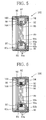
- FIGS. 13A and 13B show an elastic member 130 that is employed in a shaft sealing device of a ninth embodiment.
- the elastic member 130 has a shape of a tube containing a doughnut-shaped space 132.
- the elastic member 130 has a seal portion 134 in an innermost position as viewed in a radial direction.
- a curved portion 136 continues to the seal portion 134.
- the vertical sectional shape of the elastic member is not limited to the U-like shape of the first embodiment, and may be the shape of the letter O or J or another shape.
- FIG. 14 shows a shaft sealing device 140 of a tenth embodiment.
- the shaft sealing device 140 is fixed not to the inner circumferential surface of the shaft hole 62 but to the rotary shaft 60.
- an internal diameter of each of the ridges 144a is smaller than the external diameter d of the rotary shaft 60, and the ridges 144a are in tight contact with the outer circumferential surface of the rotary shaft 60 in a compressed state. Airtightness between the inner circumferential surface of the inner packing 144 and the outer circumferential surface of the rotary shaft 60 is thus secured by the ridges 144a.
- the case 142 is prohibited from relative rotation with respect to the rotary shaft 60.
- the seat ring 145 is fitted to the inner circumferential surface of the shaft hole 62 and sandwiched between the step surface formed in the inner circumferential surface of the shaft hole 62 and a snap ring 81.
- the seat ring 145 is therefore prohibited from relative rotation with respect to the casing 12.
- the seal portion 148 of the elastic member 146 comes into sliding contact with an inner circumferential surface of the seat ring 145.
- a low-pressure side flange 150 continues to the low-pressure side boundary of the seal portion 148 at right angles, whereas a curved portion 152 continues to the high-pressure side boundary of the seal portion 148.
- the curved portion 152 has a diameter tapering with distance from the seal portion 148 along the rotary shaft 60.
- the curved portion 152 includes a small-diameter end edge having a smaller diameter than the internal diameter of the seal portion 148, on the opposite side of the seal portion 148 as viewed in an axial direction.
- the internal diameter of the small-diameter end edge of the curved portion 152 is larger than an internal diameter of the low-pressure side flange 150.
- the high-pressure side flange 154 continues to the small-diameter end edge.
- An outer circumferential surface of the elastic member 146 is formed of the seal face 148a of the seal portion 148 and the circumferential surface 152a of the curved portion 152 that continues to one of end edges of the seal face 148a. End faces of the elastic member 146 are formed of outer surfaces of the low-pressure side and high-pressure side flanges 150 and 154.
- a circular metal support disc 158 having a hole in the center thereof is attached to the outer surface of the low-pressure side flange 150, that is, the exterior-side end face of the elastic member 146.
- a rim 160 is integrally formed in an inner circumferential edge of the support disc 158. The rim 160 is protruding from the inner circumferential edge of the support disc 158 in an opposite direction to the low-pressure side flange 150. An inner circumferential surface of the rim 160 is fitted to the outer circumferential surface of the case 142.
- the support disc 158 has an external diameter that is slightly smaller than the external diameter of the seal portion 148.
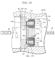
- the shaft sealing device 170 has a metal case 172.
- the case 172 includes an inner circumferential wall 172a, an outer circumferential wall 172b, and an end wall 172c connecting an end edge of the inner circumferential wall 172a and that of the outer circumferential wall 172b.
- the case 172 is in a shape of a bobbin having one open end.
- the case 172 has an outer surface that is covered with a double-cylindrical outer packing 174 made of an elastic material.
- the outer packing 174 is in tight contact with the case 172.
- the outer packing 174 has an internal diameter that is substantially equal to the external diameter d of the rotary shaft 60.
- an internal diameter of each of the ridges 174a is smaller than the external diameter d of the rotary shaft 60, and the ridges 174a are in tight contact with the outer circumferential surface of the rotary shaft 60 in a compressed state. Airtightness between the inner circumferential surface of the outer packing 174 and the outer circumferential surface of the rotary shaft 60 is thus secured by the ridges 174a.
- the case 172 is prohibited from relative rotation with respect to the rotary shaft 60.
- a spirally-extending oil groove 179 is formed in an outer surface (seal face) 178a of the seal portion 178.
- the oil groove 179 extends from an outer circumferential edge of the seal portion 178 (high-pressure side boundary) located on the crank chamber 22 side to just short of an inner circumferential edge of the seal portion 178 (low-pressure side boundary) located on the exterior side.
- a cylindrical low-pressure side circumferential wall 180 continues to the low-pressure side boundary of the seal portion 178 at right angles, whereas a curved portion 182 continues to the high-pressure side boundary of the seal portion 178.
- the curved portion 182 is gently curved away from the seat ring 175 as the curved portion 182 expands away from the seal portion 178 along the radial direction of the rotary shaft 60.
- the curved portion 182 includes a large-diameter end edge having a larger diameter than the outer circumferential edge of the seal portion 178 on the opposite side of the seal portion 178 as viewed in a radial direction.
- Axial length from the seat ring 175 to the large-diameter end edge of the curved portion 182 is shorter than axial length of the low-pressure side circumferential wall 180.
- a cylindrical high-pressure side circumferential wall 184 continues to the large-diameter end edge of the curved portion 182.
- the high-pressure side circumferential wall 184 is concentric with the low-pressure side circumferential wall 180. End edges of the high-pressure side and low-pressure side circumferential walls 184 and 180 on the end wall 172c side are substantially equal to each other in terms of axial positions.
- the end edges of the low-pressure side and high-pressure side circumferential walls 180 and 184 are in contact with the end wall 172c of the case 172.
- An outer end surface of the elastic member 176 which is located on the seat ring 175 side, is formed of the seal face 178a of the seal portion 178 and the circumferential surface 182a of the curved portion 182 that continues to the outer circumferential edge of the seal face 178a.
- the inner and outer circumferential surfaces of the elastic member 176 are formed of the outer surfaces of the low-pressure side and high-pressure side circumferential walls 180 and 184.
- a cylindrical metal spacer 186 is fitted into the case 172 from the seat ring 175 side.
- the spacer 186 is located in between a portion of the low-pressure side circumferential wall 180, which is located on the end wall 172c side, and the high-pressure side circumferential wall 184.
- Axial length of the spacer 186 is substantially equal to that of the high-pressure side circumferential wall 184.
- a doughnut-shaped space 187 is marked off between the spacer 186 and the back surface of the seal portion 178.
- a cylindrical metal support pipe 188 is attached to the outer surface of the low-pressure side circumferential wall 180, that is, the inner circumferential surface of the elastic member 176. However, a gap is secured between an end edge of the support pipe 188 and the seat ring 175.
- the inner and outer circumferential walls 172a and 172b of the case 172 sandwich the high-pressure side circumferential wall 184, the spacer 186, the low-pressure side circumferential wall 180 and the support pipe 188 in a radial direction.
- the high-pressure side circumferential wall 184 is in tight contact with the spacer 186 and the outer circumferential wall 172b
- the low-pressure side circumferential wall 180 is in tight contact with the spacer 186 and the support pipe 188.
- the space 187 is airtightly marked off by the seal portion 178, the low-pressure side circumferential wall 180, the curved portion 182 and the spacer 186.
- axial length of the elastic member 176 is longer than distance between the end wall 172b of the case and the seat ring 175.
- the seal portion 178 is brought into sliding contact with the seat ring 175 with proper pressure.
- FIG. 16 shows a shaft sealing device 190 of a twelfth embodiment.
- the shaft sealing device 190 is different from the shaft sealing device 170 in that the shaft sealing device 190 is fixed onto the casing 12 side, but is substantially the same as the shaft sealing device 170 in a part of configuration. Therefore, the same elements are provided with identical reference marks, and descriptions thereof will be omitted.
- the shaft sealing device 190 is sandwiched between the step surface of the rotary shaft 60 and a support ring 191.
- the support ring 191 is sandwiched between the step surface of the shaft hole 62 and the snap ring 81.
- An open end of the case 172 faces towards the step surface of the rotary shaft 60.
- the seal portion 178 comes into sliding contact with the step surface of the rotary shaft 60.
- An outer packing 194 in tight contact with the outer surface of the case 172 has ridges 194a in an outer circumferential surface thereof. Airtightness between the outer packing 194 and the inner circumferential surface of the shaft hole 62 is secured by the ridges 194a. There is secured a given gap in between an inner circumferential surface of the outer packing 194 and the rotary shaft 60.
- the tenth to twelfth embodiments regulate the deformation of the seal portions 148 and 178, and suppress the increase of the contact area between the seal portions 148 and 178 and the seat rings 145 and 175, or the rotary shaft 60, which serve as contact-target members.
- This facilitates the lubricating oil supply to between the seal portions 148 and 178 and the contact-target members, not to mention suppresses an increase in amount of heat produced by sliding movement. Therefore, the seal portions 148 and 178 are prevented from having high temperature and being degraded in quality. Consequently, the shaft sealing devices 140, 170 and 190 have high durability and reliability, and are inexpensive since no expensive material is required for making these shaft sealing devices. With fluid machines employing the shaft sealing devices 140, 170 and 190, power consumption is reduced.
- the pressure P of the crank chamber 22 acts upon the circumferential surfaces 152a and 182a of the curved portions 152 and 182.
- forces working in receding and pressing directions contiguously act upon the elastic members 146 and 176 across the high-pressure side boundary of the seal portions 148 and 178 on the crank chamber 22 side.
- the seal portions 148 and 178 are not detached from the contact-target members due to the pressure P of the high-pressure zone. Sealability is maintained in between the seal portions 148 and 178 and the contact-target members.
- the tenth to twelfth embodiments also may adopt the deformations that are applied to the first embodiment as seen in the second to ninth embodiments and the like.
- the shaft sealing device of the invention can be applied not only to a compressor but to various kinds of fluid machines including pumps, expansion machines, etc.
Landscapes
- Engineering & Computer Science (AREA)
- General Engineering & Computer Science (AREA)
- Mechanical Engineering (AREA)
- Sealing Devices (AREA)
- Compressor (AREA)
Applications Claiming Priority (2)
| Application Number | Priority Date | Filing Date | Title |
|---|---|---|---|
| JP2006085058 | 2006-03-27 | ||
| PCT/JP2007/056224 WO2007111305A1 (fr) | 2006-03-27 | 2007-03-26 | Système de joint pour arbre de machine hydraulique |
Publications (2)
| Publication Number | Publication Date |
|---|---|
| EP2000712A2 true EP2000712A2 (fr) | 2008-12-10 |
| EP2000712A9 EP2000712A9 (fr) | 2009-03-25 |
Family
ID=38541222
Family Applications (1)
| Application Number | Title | Priority Date | Filing Date |
|---|---|---|---|
| EP07739662A Withdrawn EP2000712A2 (fr) | 2006-03-27 | 2007-03-26 | Système de joint pour arbre de machine hydraulique |
Country Status (4)
| Country | Link |
|---|---|
| US (1) | US20100230905A1 (fr) |
| EP (1) | EP2000712A2 (fr) |
| CN (1) | CN101415972B (fr) |
| WO (1) | WO2007111305A1 (fr) |
Cited By (3)
| Publication number | Priority date | Publication date | Assignee | Title |
|---|---|---|---|---|
| WO2010130248A1 (fr) * | 2009-05-11 | 2010-11-18 | Blohm + Voss Industries Gmbh | Dispositif destiné à rendre des arbres étanches |
| WO2010139655A1 (fr) * | 2009-06-04 | 2010-12-09 | Robert Bosch Gmbh | Bague d'étanchéité d'arbre |
| DE102011077015A1 (de) * | 2011-06-06 | 2012-12-06 | Elringklinger Ag | Radialwellendichtung |
Families Citing this family (10)
| Publication number | Priority date | Publication date | Assignee | Title |
|---|---|---|---|---|
| CN102094976A (zh) * | 2011-03-11 | 2011-06-15 | 莱芜钢铁股份有限公司 | 双唇口密封圈 |
| RU2015111661A (ru) * | 2012-09-18 | 2016-10-20 | Боргварнер Инк. | Уплотнение вала турбонагнетателя |
| WO2014153414A1 (fr) * | 2013-03-22 | 2014-09-25 | Saint-Gobain Performance Plastics Corporation | Système, procédé et appareil pour ensemble joint à lèvre |
| US9599228B2 (en) * | 2013-05-06 | 2017-03-21 | Louisiana State University and Agricultural & Mechanical College | Cooled seal |
| US20150184751A1 (en) * | 2013-12-31 | 2015-07-02 | Aktiebolaget Skf | Fluid seal assembly with extruded sealing member for leakage protection |
| JP7278029B2 (ja) * | 2017-02-20 | 2023-05-19 | 株式会社オシキリ | 軸封部材、回転軸の軸封装置、横型ミキサ及びミキサ |
| JP7131278B2 (ja) * | 2018-10-10 | 2022-09-06 | 三菱瓦斯化学株式会社 | 軸封装置及び軸封システム |
| CN109980398A (zh) * | 2019-05-13 | 2019-07-05 | 四川永贵科技有限公司 | 一种电连接器接触件结构 |
| WO2021076044A1 (fr) * | 2019-10-18 | 2021-04-22 | Välinge Innovation AB | Agencement de presse continue de fabrication de panneaux de construction |
| CN111589390B (zh) * | 2020-06-02 | 2021-10-26 | 无锡职业技术学院 | 一种适用于超高压反应釜搅拌轴的轴封装置 |
Family Cites Families (14)
| Publication number | Priority date | Publication date | Assignee | Title |
|---|---|---|---|---|
| US2731282A (en) * | 1953-02-04 | 1956-01-17 | Walworth Co | Shaft seal |
| US3337222A (en) * | 1964-09-25 | 1967-08-22 | Watt V Smith | Quick acting submarine shaft seal |
| US3687464A (en) * | 1971-01-04 | 1972-08-29 | Gits Bros Mfg Co | Seal |
| JPS53163455U (fr) * | 1977-05-30 | 1978-12-21 | ||
| JPS5814284Y2 (ja) * | 1978-05-31 | 1983-03-22 | 株式会社東芝 | チュ−ブシ−ル機構 |
| US4198064A (en) * | 1978-10-31 | 1980-04-15 | Gustav Huhn Ab | Shaft seal |
| US4377312A (en) * | 1981-03-06 | 1983-03-22 | Dana Corporation | Bearing seal |
| JPS61273419A (ja) * | 1985-05-29 | 1986-12-03 | Hitachi Electronics Eng Co Ltd | 雰囲気密閉装置 |
| JPS62122960U (fr) * | 1986-01-29 | 1987-08-04 | ||
| CH679417A5 (fr) * | 1989-04-25 | 1992-02-14 | Erich Bertsch | |
| JP4396790B2 (ja) * | 1999-12-14 | 2010-01-13 | Nok株式会社 | オイルシール |
| JP2003097723A (ja) | 2001-09-25 | 2003-04-03 | Mitsubishi Cable Ind Ltd | 回転軸シール |
| JP2004156702A (ja) | 2002-11-06 | 2004-06-03 | Toyota Industries Corp | 軸封装置 |
| JP2005249104A (ja) * | 2004-03-05 | 2005-09-15 | Nok Corp | オイルシール |
-
2007
- 2007-03-26 US US12/294,697 patent/US20100230905A1/en not_active Abandoned
- 2007-03-26 WO PCT/JP2007/056224 patent/WO2007111305A1/fr not_active Ceased
- 2007-03-26 CN CN200780011667XA patent/CN101415972B/zh not_active Expired - Fee Related
- 2007-03-26 EP EP07739662A patent/EP2000712A2/fr not_active Withdrawn
Non-Patent Citations (1)
| Title |
|---|
| See references of WO2007111305A1 * |
Cited By (3)
| Publication number | Priority date | Publication date | Assignee | Title |
|---|---|---|---|---|
| WO2010130248A1 (fr) * | 2009-05-11 | 2010-11-18 | Blohm + Voss Industries Gmbh | Dispositif destiné à rendre des arbres étanches |
| WO2010139655A1 (fr) * | 2009-06-04 | 2010-12-09 | Robert Bosch Gmbh | Bague d'étanchéité d'arbre |
| DE102011077015A1 (de) * | 2011-06-06 | 2012-12-06 | Elringklinger Ag | Radialwellendichtung |
Also Published As
| Publication number | Publication date |
|---|---|
| EP2000712A9 (fr) | 2009-03-25 |
| CN101415972A (zh) | 2009-04-22 |
| CN101415972B (zh) | 2012-03-21 |
| WO2007111305A1 (fr) | 2007-10-04 |
| US20100230905A1 (en) | 2010-09-16 |
Similar Documents
| Publication | Publication Date | Title |
|---|---|---|
| EP2000712A9 (fr) | Système de joint pour arbre de machine hydraulique | |
| KR100320645B1 (ko) | 축 시일링 장치 및 이를 사용하는 압축기 | |
| JP5183938B2 (ja) | シール装置 | |
| US6322086B1 (en) | Seal structure of compressor, and the compressor | |
| US9382907B2 (en) | Vane-type compressor having an oil supply channel between the oil resevoir and vane angle adjuster | |
| JP5741554B2 (ja) | ピストン型圧縮機 | |
| EP1197687A2 (fr) | Structure d'étanchéité pour compresseur | |
| JP2004100563A (ja) | スクロール型圧縮機 | |
| KR20020090108A (ko) | 압축기 | |
| JP2005201366A (ja) | 軸封装置及び圧縮機 | |
| JP2008184926A (ja) | 往復動圧縮機 | |
| JP2007292306A (ja) | 流体機械用軸封装置 | |
| JP4121783B2 (ja) | スクロール型圧縮機 | |
| EP1162369A2 (fr) | Boítier étanche | |
| CN115768989B (zh) | 滑动部件 | |
| JP2820137B2 (ja) | スクロール気体圧縮機 | |
| EP1772627B1 (fr) | Système d'étanchéité pour compresseur | |
| JP4727468B2 (ja) | スクロール圧縮機 | |
| JP2005201336A (ja) | 軸封装置及び圧縮機 | |
| JP4706599B2 (ja) | スクロール圧縮機 | |
| JP2006002716A (ja) | 圧縮機のシール構造 | |
| JP2023157069A (ja) | オイルシール構造 | |
| WO2025041317A1 (fr) | Machine rotative à pression de fluide | |
| WO2009128228A1 (fr) | Structure de distribution d'agent lubrifiant pour compresseur | |
| JP2008045493A (ja) | ラジアルピストンポンプまたはモータ |
Legal Events
| Date | Code | Title | Description |
|---|---|---|---|
| PUAI | Public reference made under article 153(3) epc to a published international application that has entered the european phase |
Free format text: ORIGINAL CODE: 0009012 |
|
| 17P | Request for examination filed |
Effective date: 20080925 |
|
| AK | Designated contracting states |
Kind code of ref document: A2 Designated state(s): DE FR |
|
| PUAB | Information related to the publication of an a document modified or deleted |
Free format text: ORIGINAL CODE: 0009199EPPU |
|
| DAX | Request for extension of the european patent (deleted) | ||
| RBV | Designated contracting states (corrected) |
Designated state(s): DE FR |
|
| STAA | Information on the status of an ep patent application or granted ep patent |
Free format text: STATUS: THE APPLICATION IS DEEMED TO BE WITHDRAWN |
|
| 18D | Application deemed to be withdrawn |
Effective date: 20101001 |