EP2000603A2 - Système de drainage - Google Patents
Système de drainage Download PDFInfo
- Publication number
- EP2000603A2 EP2000603A2 EP08009761A EP08009761A EP2000603A2 EP 2000603 A2 EP2000603 A2 EP 2000603A2 EP 08009761 A EP08009761 A EP 08009761A EP 08009761 A EP08009761 A EP 08009761A EP 2000603 A2 EP2000603 A2 EP 2000603A2
- Authority
- EP
- European Patent Office
- Prior art keywords
- drainage
- drain pipe
- downcomer
- hood
- marked
- Prior art date
- Legal status (The legal status is an assumption and is not a legal conclusion. Google has not performed a legal analysis and makes no representation as to the accuracy of the status listed.)
- Granted
Links
- 239000012530 fluid Substances 0.000 claims abstract description 72
- 238000011144 upstream manufacturing Methods 0.000 claims description 3
- 238000007789 sealing Methods 0.000 claims description 2
- 230000004888 barrier function Effects 0.000 claims 1
- 238000009792 diffusion process Methods 0.000 claims 1
- 239000003779 heat-resistant material Substances 0.000 claims 1
- 239000007788 liquid Substances 0.000 description 16
- 239000010802 sludge Substances 0.000 description 12
- QVGXLLKOCUKJST-UHFFFAOYSA-N atomic oxygen Chemical compound [O] QVGXLLKOCUKJST-UHFFFAOYSA-N 0.000 description 8
- 239000001301 oxygen Substances 0.000 description 8
- 229910052760 oxygen Inorganic materials 0.000 description 8
- 239000012535 impurity Substances 0.000 description 4
- 229910001220 stainless steel Inorganic materials 0.000 description 4
- 239000010935 stainless steel Substances 0.000 description 4
- 238000013461 design Methods 0.000 description 3
- 238000011161 development Methods 0.000 description 3
- 230000018109 developmental process Effects 0.000 description 3
- 239000000463 material Substances 0.000 description 3
- 230000015572 biosynthetic process Effects 0.000 description 2
- 239000000356 contaminant Substances 0.000 description 2
- 230000000694 effects Effects 0.000 description 2
- 238000000034 method Methods 0.000 description 2
- 239000013618 particulate matter Substances 0.000 description 2
- 230000008569 process Effects 0.000 description 2
- 230000007704 transition Effects 0.000 description 2
- XLYOFNOQVPJJNP-UHFFFAOYSA-N water Substances O XLYOFNOQVPJJNP-UHFFFAOYSA-N 0.000 description 2
- 206010003497 Asphyxia Diseases 0.000 description 1
- 240000001439 Opuntia Species 0.000 description 1
- 235000004727 Opuntia ficus indica Nutrition 0.000 description 1
- 229910000831 Steel Inorganic materials 0.000 description 1
- 230000009471 action Effects 0.000 description 1
- 230000032683 aging Effects 0.000 description 1
- 230000000903 blocking effect Effects 0.000 description 1
- 238000006243 chemical reaction Methods 0.000 description 1
- 238000004140 cleaning Methods 0.000 description 1
- 230000003749 cleanliness Effects 0.000 description 1
- 230000007797 corrosion Effects 0.000 description 1
- 238000005260 corrosion Methods 0.000 description 1
- 230000003111 delayed effect Effects 0.000 description 1
- 230000001419 dependent effect Effects 0.000 description 1
- 238000011010 flushing procedure Methods 0.000 description 1
- 239000002737 fuel gas Substances 0.000 description 1
- 239000003502 gasoline Substances 0.000 description 1
- 238000003780 insertion Methods 0.000 description 1
- 230000037431 insertion Effects 0.000 description 1
- 238000007689 inspection Methods 0.000 description 1
- 230000001788 irregular Effects 0.000 description 1
- -1 leaves Substances 0.000 description 1
- 238000012423 maintenance Methods 0.000 description 1
- 238000004519 manufacturing process Methods 0.000 description 1
- 238000000465 moulding Methods 0.000 description 1
- 230000035515 penetration Effects 0.000 description 1
- 239000002244 precipitate Substances 0.000 description 1
- 238000009417 prefabrication Methods 0.000 description 1
- 230000009467 reduction Effects 0.000 description 1
- 238000009418 renovation Methods 0.000 description 1
- 230000008439 repair process Effects 0.000 description 1
- 238000009420 retrofitting Methods 0.000 description 1
- 230000000630 rising effect Effects 0.000 description 1
- 239000002689 soil Substances 0.000 description 1
- 239000007787 solid Substances 0.000 description 1
- 230000007480 spreading Effects 0.000 description 1
- 238000003892 spreading Methods 0.000 description 1
- 239000010959 steel Substances 0.000 description 1
- 239000000126 substance Substances 0.000 description 1
- 230000009747 swallowing Effects 0.000 description 1
Images


Classifications
-
- E—FIXED CONSTRUCTIONS
- E03—WATER SUPPLY; SEWERAGE
- E03F—SEWERS; CESSPOOLS
- E03F5/00—Sewerage structures
- E03F5/04—Gullies inlets, road sinks, floor drains with or without odour seals or sediment traps
- E03F5/0407—Floor drains for indoor use
-
- E—FIXED CONSTRUCTIONS
- E03—WATER SUPPLY; SEWERAGE
- E03F—SEWERS; CESSPOOLS
- E03F5/00—Sewerage structures
- E03F5/04—Gullies inlets, road sinks, floor drains with or without odour seals or sediment traps
- E03F2005/0416—Gullies inlets, road sinks, floor drains with or without odour seals or sediment traps with an odour seal
- E03F2005/0418—Gullies inlets, road sinks, floor drains with or without odour seals or sediment traps with an odour seal in the form of a bell siphon
Definitions
- the invention relates to a drainage system for a surface or road o. The like.
- a drainage system for a surface or road o. The like.
- burning fluids can flow into the drainage system after accidents or fires and so can transport a punctual fire so that spreads this area.
- the present invention seeks to design a drainage system so that a spread of a punctual fire on the drainage system is effectively prevented.
- This object is achieved by the combination of features of claim 1 by simple means in an inventive manner.
- the dependent claims contain in part expedient and in part self-inventive developments of the invention.
- the inventive drainage system consists of one or more drainage pipes. In each of these lines run-offs open at regular or irregular intervals. In particular, such an arrangement of roadways is known, on which edges at certain intervals drainage shafts are arranged. Above all, the invention is suitable for fire-protected drainage of tunnel lanes, in which the drainage lines due to the fluidic conditions in the tunnel burning fluids forward very quickly, so spread especially in tunnels fires on the drainage pipes unusually fast.
- a drain pipe is first introduced.
- This drain pipe protrudes with its inlet end vertically into the downcomer.
- the end of the drain pipe facing away from the inlet end opens into the bottom or a side wall of the downcomer.
- the vertical projecting into the downcomer drainpipe forms as it were a standpipe.
- a bell-shaped hood is slipped.
- the slipped hood leaves both a radial gap between their hood inner shell on the one hand and the Wegrohrauraußenmantel on the other hand free.
- the inside of the top surface of the hood is not located on the opening edge of the inlet opening, but is also arranged at a distance from the opening edge of the inlet opening to release here also a drain gap for the fluid to be discharged.
- the fluid to be discharged first runs into the downcomer and fills it up to the height of the opening edge of the inlet opening of the drainage pipe. Only when the liquid level of the fluid to be discharged exceeds the height level of the opening edge, the fluid to be discharged flows through the inlet opening into the drain pipe.
- the fluid does not flow directly into the drain pipe, but previously passed the drain gap formed between the hood and the inlet end of the drain pipe. If such a large amount of fluid introduced into the downcomer that the current fluid level projects beyond the height of the drain pipe, the fluid according to the law of communicating tubes is pumped even with overpressure through the flow gap as it were.
- the cross-sectional area of the drainage gap is dimensioned in particular such that it is equal to or greater than the free cross-sectional area of the drainage pipe.
- the amount of liquid that can be transported away via the discharge pipe continues to depend on the cross-sectional area of the discharge pipe, but not on the cross-sectional area of the discharge gap.
- the fluid is discharged via the drainage line without burning further.
- a spreading of the punctual fire is effectively prevented by the fluid passed through the drainage line.
- the hood outer wall acts as a baffle.
- impurities floating on the fluid surface or an oil film formed on the fluid surface can not enter the drainpipe from the drainage gap.
- a rough pre-cleaning of the discharged from the drain pipe fluid can not enter the drainpipe from the drainage gap.
- the invention is therefore particularly suitable for use in traffic tunnels and enclosures and on operating surfaces of the process industry, in particular the chemical industry, refineries or the like.
- the drainpipe has a diameter of DN100 and the hood has a diameter of DN200.
- the diameter of the drain pipe leading away drain pipe is at a diameter of DN150.
- the swallowing capacity is about 15 l / s. In other words, 15 l of fluid can be diverted from the downcomer per second.
- the flow gap between the hood inner shell anddiagrohrau is advantageous to design as a circumferential gap with preferably constant gap width. In this way, a comparatively large amount of fluid can be transported away while maintaining the interruption of the oxygen supply in the outlet gap.
- Claim 3 relates to an embodiment of the invention with a double function of the hood.
- the hood is arranged movable relative to the drain pipe.
- the hood is displaced in this way in the vertical direction between an open position and a closed position back and forth.
- the open position is unchanged from the functional position of the rigid variant of the invention with respect to the drain pipe stationary fixed hood.
- the hood is moved in the vertical direction on the drain pipe so far toward the bottom of the downcomer until a arranged on the inside of the hood closure cover or the top surface of the hood rests firmly on the opening edge of the inlet opening and the inlet opening so tight closes.
- the hood In order to ensure the automatic liquid drainage when the drainpipe is closed, the hood is designed so that it swims upwards in the downcomer as the liquid level rises. Thus, the flow gap between the top surface of the hood and the opening edge of the inlet opening is released again, so that the fluid can escape through the flow gap unhindered.
- the hood is in this case secured to the drain pipe so that a floating of the hood beyond the open position, in which the flow gap is completely released, effectively prevented.
- the fluid drains below the burning fluid surface. If the liquid level drops, the cover arranged on the hood inner shell closes the inlet opening of the drain pipe again. A penetration of burning fluid is thus safely avoided when the liquid level drops.
- Claims 4 and 5 relate to two different possible arrangements of the drain pipe in the downcomer.
- the drain pipe opens into the bottom of the downcomer. It is therefore a vertically extending, strictly cylindrical pipe section.
- the embodiment according to claim 5 relates to an arcuate pipe section, which opens into a side wall of the downcomer. Both variants are well suited for insertion into existing drain lines in the bottom or a side wall of the drain shaft.
- the annular space between the Jardinrohrauraumantel and the associated mouth opening in the bottom or in the side wall is additionally secured by an annular seal.
- the ring seal can also compensate for dimensional accuracy or other tolerance errors.
- the additional clamping plates are provided according to claim 7.
- the claims 8 and 9 relate to an alternative embodiment of the fixation of the drain pipes at the bottom or the side wall of the downcomer.
- a mounting flange is arranged at the end of the drain pipe in the region of the outlet opening.
- the drain pipe can be fixed either on the floor or on a side wall of the drainage shaft with several screws.
- to switch between the mounting flange and the mounting flange holding the bottom or the mounting flange holding side wall between a gap seal to switch between the mounting flange and the mounting flange holding the bottom or the mounting flange holding side wall between a gap seal. This variant also prevents unwanted escape of the fluid outside of the drain pipe.
- Claim 11 finally includes an embodiment of the invention with an upstream in the flow direction of the drain pipe sludge buckets in the downcomer.
- a sludge bucket favors keeping the downcomer clean because leaves, mud and other contaminants are collected in the sludge bucket.
- the end grate In order to keep the discharge shaft clean, the end grate must be lifted off the drain shaft and then the sludge bucket lifted out, emptied and cleaned.
- the sludge bucket throttles and evenifies the amount of liquid supplied to the downcomer. As a result, the risk of a strong turbulence of the fluid before it enters the outlet gap, combined with the possible discharge of a local fire source via the outlet gap into the drain tube, is low.
- the invention also favors the cleanliness of the drainage shaft. Due to the flow gap can be due to the two-way reversal and the reduction of the flow velocity of the fluid Impurities in the fluid, particulate matter contained in the fluid and solids, penetrate only to a limited extent in the drain pipe. The impurities are deposited outside the drainpipe at the bottom of the downcomer, where they can easily be skimmed off or sucked off.
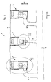
- a drainage system 1 has a drainage channel 3 formed in the longitudinal direction 2.
- the drainage system 1 is shown in a longitudinal section 2 cut side view.
- the gutter 3 is at the edge of a in the Fig. 1 not shown roadway arranged.
- the drainage system 1 has in the longitudinal direction 2 a plurality of spaced-apart drainage shafts 4.
- the downcomers 4 break through the gutter 3 and lead substantially in the vertical direction 5 in the ground.
- Each downcomer 4 is connected by means of a drain line 6 with a longitudinal direction 2 extending drainage line 7.
- A for example, due to a precipitate on the roadway accumulating liquid is passed through the gutter 3, the drain chutes 4 and the drain lines 6 to the drainage line 7 and discharged from this.
- Fig. 1 In this case, only a section of the gutter 3 with three downcomers 4 is shown.
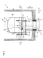
- Fig. 2 shows the first variant of the downcomer 4.
- the downcomer 4 is a downwardly from the gutter 3 from substantially in the vertical direction 5 downwardly extending and closed down cuboid hollow body.
- the hollow body has four side walls 8 and a bottom 9. He is poured from a concrete. On one of the side walls 8 near the bottom 9, a circular mouth opening 10 is arranged. In this mouth opening 10, the end of the drain line 6 is attached.
- the drain line 6 in turn leads to the drainage line 7, as shown in the Fig. 1 is shown.
- a drain pipe 11 opens.
- the drain pipe 11 is designed as a 90 ° elbow. It protrudes with its inlet end 12 in the vertical direction 5 into the downcomer 4.
- the outlet end 12 facing away from the drain end 13 opens with its outlet opening 13 'in the drain line 6.
- the drain pipe 11 is held with its furnishrohrau joint 14 of an inserted into the end of the drain line 6 annulus seal 15.
- the annular space seal 15 seals the annular space formed between the drain pipe outer casing 14 and the inside of the drainage pipe 11.
- the annular space seal 15 is fixed in position by means of clamping plates 16.
- a bell-shaped hood 18 is slipped.
- the hood 18 is designed as a hollow cylinder which is closed in the vertical direction 5 upwards by a top surface 19 designed as a dished bottom.
- At NASArohrauraumantel 14 is in the region of the inlet end 12 of the drain pipe 11 in the vertical direction 5 upwardly extending and the hood 18 at its free end by cross-retaining pin 20 is attached.
- the retaining bolt 20 connects via a wing nut 21, the hood 18 releasably connected to the inlet end 12. In this way, a spacing of the hood 18 to the inlet end 12 of the drain pipe 11 is reached.
- a drain gap 25 is formed both between a portion of the hood inner shell 22 and the Hurley dry condition 14 and between the inside 23 of the top surface 19 of the hood 18 and the opening edge 24 of the inlet opening 17.
- This outlet gap 25 has the geometry of an annular gap with a constant gap width in the area in which the hood 18 covers the downpipe 12.
- the interior of the downcomer 4 forms a fluid collection chamber 28.
- the fluid taken up by the fluid collection chamber 28 may also be a burning liquid such as gasoline, due to an accident occurring on the roadway in the downcomer 4 and thus in the Fluid collection chamber 28 enters.
- Coarse impurities contained in the fluid, such as leaves, stones or the like, are collected in the sludge bucket 27.
- the sludge bucket 27 also limits the amount of fluid flowing to the fluid collection chamber 28 per unit time.
- the fluid fills up the fluid collection chamber 28 up to the height of the opening edge 24 of the inlet opening 17 of the drainage pipe 11. If the liquid level of the fluid exceeds the height level of the opening edge 24, the fluid flows through the inlet opening 17 into the drainage pipe 11 and is led via the drainage line 6 to the drainage line 7.
- the fluid is not passed directly, but via the detour of the flow gap 25 in the drain pipe 11. Therefore, there are two effects.
- a discharge of the fluid takes place with a time delay only when the liquid level of the fluid is above the height level of the opening edge 24.
- particulate matter contained in the fluid which has passed through the recesses 26 of the sludge pail 27, settles on the bottom 9 of the downcomer 4 due to a slowing down of the flow velocity of the fluid. The suspended matter thus does not reach the drain line 6.
- the oxygen supply to the fluid is interrupted abruptly. If it is a burning fluid, the flame holding the fluid burning is safely smothered. In this way it is ensured that the burning fluid is not entered into the drain line 6. Rather, it comes at best to a local fire in the downcomer 4. An extension of the fire is thus effectively avoided.
- the sludge bucket 27 causes throttling and equalization of the amount of liquid supplied to the downcomer 4. This avoids a surge-like entry of the fluid into the outlet gap 25. Fire pockets trapped in air bubbles in the fluid can thus not enter the drainage pipe 6.
- the drain pipe 11 and the hood 18 can withstand fire, they are made of a heat-resistant stainless steel.
- This stainless steel is for example V4A.
- V4A is not only heat resistant, but also resistant to corrosion and aging.
- all other components, such as the retaining bolts 21 or the clamping plates 16, which may be exposed to fire, are advantageously made of such a stainless steel. All components can be pickled and passivated as additional protection.
- the wing nut 21 allows rapid disassembly of the hood 18 for inspection purposes or for flushing the drain pipe. 6
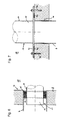
- Fig. 3 shows the downcomer according to arrow III in Fig. 2 seen again from the side of the drain pipe 6 ago. Also visible is a pipe flange 29, via which the drain line 6 can be screwed either to another pipe section of the drain line 6 or to the drainage line 7. This pipe flange 29 is in the Fig. 2 not shown.
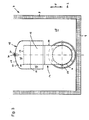
- Fig. 4 shows in a longitudinal section in the vertical direction 5, the second variant of the downcomer 4 from Fig. 1
- Fig. 5 shows the downcomer Fig. 4 in a cross section transverse to the vertical direction 5 according to the in Fig. 4 Plotted sectional plane VV.
- the Indian Fig. 1 to be seen upper portion of the downcomer with the Schlämmimer is in the Fig. 4 and 5 not shown.
- the functioning of the in the Fig. 4 and 5 Downstream well 4 essentially corresponds to the in the Fig. 2 and 3 illustrated variant. It is therefore only discussed the differences to this variant.
- the drain line 6 is arranged centrally in the bottom 9 of the downcomer 4 in a mouth opening 10.
- the drain pipe 11 is formed as a straight pipe piece extending in the vertical direction 5. It's like the drainpipe in the FIG. 2 and 3 held by an annulus seal 15 in the drain line 6 and sealed against it.
- the hood 18 is arranged opposite the drain pipe 11 in the vertical direction 5 movable. For this purpose, the hood 18 has on its outside three guide tabs 31 arranged in the radial direction 30. Furthermore, a stud holder 32 is attached to the inlet end 12 of the drain pipe 11 at readilyrohrauraumantel.
- the bolt holder 32 is embodied as a bolt circle welded onto the drain pipe outside jacket, which has three retaining tabs 34 projecting in the radial direction 30. At each retaining tab 34, a guide pin 35 is attached end. Each guide pin 35 passes through an inserted into a guide plate 31 recess in a guide sleeve inserted into the recess 36. At the vertically upward of the retaining tab 34 opposite side, each guide pin 35 held by a wing nut 21, pushed onto the guide pin 35 End stop 37 on. In the area of the guide lugs 31, a closure cover 38, which is designed as a circular disk and extends over the entire hood cross-section, is fastened to the hood inner casing 22.
- This closure cap 38 is in the closed position of the hood 18 on a on the opening edge 24 arranged around seal 40. As a result, it closes the inlet opening 17 and seals it.
- the seal 40 is designed as a plug-on rubber seal which receives the opening edge 24 in its interior.
- the hood 18 is lifted upwards in a vertical direction 5 by buoyancy according to the Archimedean principle, starting at a certain liquid level. If further fluid flows in, the hood 18 will be up to its in the Fig. 4 raised dashed opening position raised. This open position is predetermined by the three end stops 37 of the three guide pins 35.
- the hood 18 is raised in the vertical direction 5 and the closure cap 38 releases the inlet opening 17 of the drainage tube 6. The fluid drains below its burning surface. If the liquid level drops again, the hood 18 moves in the vertical direction 5 towards the bottom 9 of the downcomer 9. Of the Closure lid 38 closes the inlet opening 17 again. This ensures that no burning fluid enters the drainpipe 6.
- the variant with the movably mounted hood 18 is also suitable for a downcomer 4, which has no sludge bucket 27 upstream of the fluid collection chamber 28 for throttling the amount of liquid supplied to the fluid collection chamber 28.
- the inlet end 12 cross hood 18 also prevents coarse contaminants, such as branches or the like, between the cap 38 and the seal 40 are clamped and affect the sealing effect of the cap 38.
- the total of three wing nuts 21 allow easy disassembly of the hood 18 for maintenance purposes.
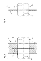
- Fig. 6 shows a side wall 8 of a downcomer 4, in which in a mouth opening 10, a drain line 6 is fixed. Both Fig. 6 to 9 is in each case the drain line 11 into the fluid interior 28 continued to think so that its inlet end 12 extends with the hood 18 arranged thereon in the vertical direction 5.
- a concentric annular space seal 15 is arranged, which is held by means of two executed as a bolted clamping plates in position at the end of the drain line 6.
- the drain pipe 11 is inserted with its discharge end 13 and fixed and held by the annulus seal 15.
- the annular space formed between the drain outside 14 of the drain pipe 11 and the inside of the drain line 11 is thus effectively sealed.
- a drain pipe 11 can be retrofitted with attached hood 18 in an existing downcomer.
- Fig. 7 shows a bottom 9 of a downcomer 4 with an inserted into a mouth opening 10 in the bottom 9 drain line 6.
- a drain pipe 11 is attached to the bottom 9.
- the attachment of the drain pipe 11 via a welded at its outlet end 13 on designingrohrau jointmantel 14 mounting flange 41.
- the mounting flange 41 is screwed by means of retaining dowels 42 to the bottom 9.
- a gap seal 43 is clamped between the mounting flange 41 and the bottom 9.
- a drain pipe 11 with a hood 18 arranged thereon can be retrofitted in an easy way into an existing downcomer.
- the gap seal 43 prevents at the material transition between the bottom 9 and drain line 6 caused by capillary leakage currents along the outer jacket of the drain line. 6
- Fig. 8 shows a side wall 8 of a downcomer 4, which is cast from concrete.
- the drain pipe 11 is poured into the side wall 8 and is held in a form-fitting manner by the surrounding side wall 8.
- the drain pipe 11 a circumferential wall ring 44 which is welded to the professionrohrauraumantel 14.
- the wall ring 44 prevents leakage currents, which could otherwise leave the fluid collection chamber 28 at the transition between theticianrohrau tomantel and the side wall 8 without being discharged through the drain line 6.
- the side walls 8 and the bottom 9 of the downcomer 4 can also be made of a steel.
- a stainless steel, such as V4A is suitable.
- the drain pipe 11 can be fixed in a simple manner in a recess introduced into the side wall 8 'by a weld seam along the outer jacket 14.
Landscapes
- Health & Medical Sciences (AREA)
- Life Sciences & Earth Sciences (AREA)
- Engineering & Computer Science (AREA)
- Hydrology & Water Resources (AREA)
- Public Health (AREA)
- Water Supply & Treatment (AREA)
- Sewage (AREA)
- Sink And Installation For Waste Water (AREA)
- Duct Arrangements (AREA)
- Separating Particles In Gases By Inertia (AREA)
Applications Claiming Priority (1)
| Application Number | Priority Date | Filing Date | Title |
|---|---|---|---|
| DE200720008019 DE202007008019U1 (de) | 2007-06-05 | 2007-06-05 | Entwässerungssystem |
Publications (3)
| Publication Number | Publication Date |
|---|---|
| EP2000603A2 true EP2000603A2 (fr) | 2008-12-10 |
| EP2000603A3 EP2000603A3 (fr) | 2010-07-28 |
| EP2000603B1 EP2000603B1 (fr) | 2015-04-29 |
Family
ID=39708729
Family Applications (1)
| Application Number | Title | Priority Date | Filing Date |
|---|---|---|---|
| EP20080009761 Not-in-force EP2000603B1 (fr) | 2007-06-05 | 2008-05-29 | Système de drainage |
Country Status (3)
| Country | Link |
|---|---|
| EP (1) | EP2000603B1 (fr) |
| AT (1) | AT13081U1 (fr) |
| DE (1) | DE202007008019U1 (fr) |
Families Citing this family (3)
| Publication number | Priority date | Publication date | Assignee | Title |
|---|---|---|---|---|
| CZ306259B6 (cs) * | 2014-01-24 | 2016-11-02 | Cs-Beton S.R.O. | Štěrbinová trouba s protipožárním uzávěrem odvodňovacího systému a jeho použití |
| ES2555671B1 (es) * | 2014-07-04 | 2016-09-20 | Baroan Rioja, S.L. | Dispositivo de desagüe con orificio de entrada no circular |
| DE102018121292A1 (de) * | 2018-08-31 | 2020-03-05 | ACO Severin Ahlmann GmbH & Co Kommanditgesellschaft | Entwässerungsschacht und Entwässerungssystem |
Family Cites Families (9)
| Publication number | Priority date | Publication date | Assignee | Title |
|---|---|---|---|---|
| DE3639285C2 (de) * | 1986-11-18 | 1995-11-09 | Bernhard Kessel | Bodenablauf |
| DE4015393A1 (de) * | 1990-05-14 | 1991-11-21 | Dallmer Gmbh & Co | Ablaufarmatur fuer fussboeden oder daecher |
| DE9317849U1 (de) * | 1993-11-23 | 1994-02-10 | Passavant-Werke Ag, 65326 Aarbergen | Bodenablauf |
| GB2285460B (en) * | 1993-12-14 | 1997-01-08 | Harmer Holdings Ltd | Syphonic rainwater outlet |
| DE29606174U1 (de) * | 1996-04-03 | 1996-06-20 | Passavant-Werke Ag, 65326 Aarbergen | Boden- oder Deckenablauf mit eingebautem Geruchverschlußteil |
| DE20200625U1 (de) * | 2001-12-12 | 2002-04-11 | Aco Severin Ahlmann Gmbh & Co. Kg, 24768 Rendsburg | Brandschutzablauf |
| ES2254801T3 (es) * | 2002-04-29 | 2006-06-16 | DALLMER GMBH & CO. KG | Elemento de construccion para la proteccion contra incendios de un dispositivo de drenaje y dispositivo de drenaje con tal elemento de construccion. |
| DE102004007454A1 (de) * | 2003-02-14 | 2004-08-26 | Dallmer Gmbh & Co. Kg | Ablaufvorrichtung zur Montage in einer Boden- oder Deckenöffnung |
| DE202004019658U1 (de) * | 2004-12-20 | 2005-02-17 | Basika Entwässerungen GmbH | Bodenablauf |
-
2007
- 2007-06-05 DE DE200720008019 patent/DE202007008019U1/de not_active Expired - Lifetime
-
2008
- 2008-05-29 EP EP20080009761 patent/EP2000603B1/fr not_active Not-in-force
- 2008-05-29 AT ATGM168/2012U patent/AT13081U1/de not_active IP Right Cessation
Also Published As
| Publication number | Publication date |
|---|---|
| EP2000603A3 (fr) | 2010-07-28 |
| AT13081U1 (de) | 2013-05-15 |
| EP2000603B1 (fr) | 2015-04-29 |
| DE202007008019U1 (de) | 2008-10-16 |
Similar Documents
| Publication | Publication Date | Title |
|---|---|---|
| DE69534021T2 (de) | Auffangbehälter | |
| EP2000603B1 (fr) | Système de drainage | |
| EP2508686B1 (fr) | Installation de retenue pour l'eau de précipitation et les eaux usées | |
| EP2157252A2 (fr) | Branchement ou siphon amélioré doté d'un dispositif de soutien pour liquides légers | |
| DE102009048037B4 (de) | Filtereinrichtung für Dachentwässerungssysteme | |
| DE60201009T2 (de) | Zweiwege-siphon | |
| CH658088A5 (de) | Abwasserablauf, bestehend aus einem ablaufbehaelter mit mindestens einem zulauf und einem ablaufrohr sowie verwendung desselben. | |
| WO2015075232A1 (fr) | Dispositif d'écoulement ainsi qu'élément tubulaire intérieur destiné à être au moins en partie inséré dans une tubulure d'entrée | |
| EP1507045A1 (fr) | Bouche d'égout dans le sol ou la chaussée avec un dispositif de retenue de liquides legères | |
| DE102005016526B3 (de) | Absperrvorrichtung für einen Abwasserkontrollschacht | |
| DE19608201C2 (de) | Sickerschacht zum Ableiten von Abwasser in den Boden | |
| DE10107496B4 (de) | Vorrichtung zur Vermeidung von Gasaustritt in einem Abwasserschacht | |
| EP3069773A2 (fr) | Dispositif de filtre pour un transporteur destine a transporter des liquides contenant des matieres solides et/ou des dechets | |
| AT412887B (de) | Rohrreinigungseinrichtung | |
| EP3889517A1 (fr) | Dispositif de renvoi de condensat | |
| EP1394328A1 (fr) | Soupape de non-retour pour conduites de décharge | |
| DE202004012641U1 (de) | Straßen- oder Bodeneinlauf mit Rückhalteeinrichtung für Leichtflüssigkeiten | |
| DE2558642A1 (de) | Reinigungsrohr | |
| EP2154300A1 (fr) | Station d'eaux usées | |
| DE9011346U1 (de) | Fallrohr für Regensammler | |
| DE29811844U1 (de) | Regenwasser-Zisterne | |
| DE102023123033A1 (de) | Tankanlage | |
| DE102010006801A1 (de) | Dachentwässerung (roof drain) | |
| EP1837447A1 (fr) | Urinoir | |
| DE20113627U1 (de) | Bauwasserentnahmevorrichtung |
Legal Events
| Date | Code | Title | Description |
|---|---|---|---|
| PUAI | Public reference made under article 153(3) epc to a published international application that has entered the european phase |
Free format text: ORIGINAL CODE: 0009012 |
|
| AK | Designated contracting states |
Kind code of ref document: A2 Designated state(s): AT BE BG CH CY CZ DE DK EE ES FI FR GB GR HR HU IE IS IT LI LT LU LV MC MT NL NO PL PT RO SE SI SK TR |
|
| AX | Request for extension of the european patent |
Extension state: AL BA MK RS |
|
| RAP1 | Party data changed (applicant data changed or rights of an application transferred) |
Owner name: RAIMUNG HOELLEIN CAROLINENHUETTE GMBH |
|
| PUAL | Search report despatched |
Free format text: ORIGINAL CODE: 0009013 |
|
| AK | Designated contracting states |
Kind code of ref document: A3 Designated state(s): AT BE BG CH CY CZ DE DK EE ES FI FR GB GR HR HU IE IS IT LI LT LU LV MC MT NL NO PL PT RO SE SI SK TR |
|
| AX | Request for extension of the european patent |
Extension state: AL BA MK RS |
|
| 17P | Request for examination filed |
Effective date: 20110126 |
|
| AKX | Designation fees paid |
Designated state(s): AT BE BG CH CY CZ DE DK EE ES FI FR GB GR HR HU IE IS IT LI LT LU LV MC MT NL NO PL PT RO SE SI SK TR |
|
| 17Q | First examination report despatched |
Effective date: 20120529 |
|
| RAP1 | Party data changed (applicant data changed or rights of an application transferred) |
Owner name: HOELLKO GMBH |
|
| GRAP | Despatch of communication of intention to grant a patent |
Free format text: ORIGINAL CODE: EPIDOSNIGR1 |
|
| INTG | Intention to grant announced |
Effective date: 20141113 |
|
| GRAS | Grant fee paid |
Free format text: ORIGINAL CODE: EPIDOSNIGR3 |
|
| GRAA | (expected) grant |
Free format text: ORIGINAL CODE: 0009210 |
|
| AK | Designated contracting states |
Kind code of ref document: B1 Designated state(s): AT BE BG CH CY CZ DE DK EE ES FI FR GB GR HR HU IE IS IT LI LT LU LV MC MT NL NO PL PT RO SE SI SK TR |
|
| REG | Reference to a national code |
Ref country code: GB Ref legal event code: FG4D Free format text: NOT ENGLISH |
|
| REG | Reference to a national code |
Ref country code: CH Ref legal event code: EP |
|
| REG | Reference to a national code |
Ref country code: AT Ref legal event code: REF Ref document number: 724532 Country of ref document: AT Kind code of ref document: T Effective date: 20150515 |
|
| REG | Reference to a national code |
Ref country code: IE Ref legal event code: FG4D Free format text: LANGUAGE OF EP DOCUMENT: GERMAN |
|
| REG | Reference to a national code |
Ref country code: DE Ref legal event code: R096 Ref document number: 502008012928 Country of ref document: DE Effective date: 20150611 |
|
| REG | Reference to a national code |
Ref country code: NL Ref legal event code: VDEP Effective date: 20150429 |
|
| REG | Reference to a national code |
Ref country code: LT Ref legal event code: MG4D |
|
| PG25 | Lapsed in a contracting state [announced via postgrant information from national office to epo] |
Ref country code: NL Free format text: LAPSE BECAUSE OF FAILURE TO SUBMIT A TRANSLATION OF THE DESCRIPTION OR TO PAY THE FEE WITHIN THE PRESCRIBED TIME-LIMIT Effective date: 20150429 |
|
| PG25 | Lapsed in a contracting state [announced via postgrant information from national office to epo] |
Ref country code: NO Free format text: LAPSE BECAUSE OF FAILURE TO SUBMIT A TRANSLATION OF THE DESCRIPTION OR TO PAY THE FEE WITHIN THE PRESCRIBED TIME-LIMIT Effective date: 20150729 Ref country code: LT Free format text: LAPSE BECAUSE OF FAILURE TO SUBMIT A TRANSLATION OF THE DESCRIPTION OR TO PAY THE FEE WITHIN THE PRESCRIBED TIME-LIMIT Effective date: 20150429 Ref country code: ES Free format text: LAPSE BECAUSE OF FAILURE TO SUBMIT A TRANSLATION OF THE DESCRIPTION OR TO PAY THE FEE WITHIN THE PRESCRIBED TIME-LIMIT Effective date: 20150429 Ref country code: FI Free format text: LAPSE BECAUSE OF FAILURE TO SUBMIT A TRANSLATION OF THE DESCRIPTION OR TO PAY THE FEE WITHIN THE PRESCRIBED TIME-LIMIT Effective date: 20150429 Ref country code: HR Free format text: LAPSE BECAUSE OF FAILURE TO SUBMIT A TRANSLATION OF THE DESCRIPTION OR TO PAY THE FEE WITHIN THE PRESCRIBED TIME-LIMIT Effective date: 20150429 Ref country code: PT Free format text: LAPSE BECAUSE OF FAILURE TO SUBMIT A TRANSLATION OF THE DESCRIPTION OR TO PAY THE FEE WITHIN THE PRESCRIBED TIME-LIMIT Effective date: 20150831 |
|
| PG25 | Lapsed in a contracting state [announced via postgrant information from national office to epo] |
Ref country code: GR Free format text: LAPSE BECAUSE OF FAILURE TO SUBMIT A TRANSLATION OF THE DESCRIPTION OR TO PAY THE FEE WITHIN THE PRESCRIBED TIME-LIMIT Effective date: 20150730 Ref country code: IS Free format text: LAPSE BECAUSE OF FAILURE TO SUBMIT A TRANSLATION OF THE DESCRIPTION OR TO PAY THE FEE WITHIN THE PRESCRIBED TIME-LIMIT Effective date: 20150829 Ref country code: LV Free format text: LAPSE BECAUSE OF FAILURE TO SUBMIT A TRANSLATION OF THE DESCRIPTION OR TO PAY THE FEE WITHIN THE PRESCRIBED TIME-LIMIT Effective date: 20150429 |
|
| PG25 | Lapsed in a contracting state [announced via postgrant information from national office to epo] |
Ref country code: MC Free format text: LAPSE BECAUSE OF FAILURE TO SUBMIT A TRANSLATION OF THE DESCRIPTION OR TO PAY THE FEE WITHIN THE PRESCRIBED TIME-LIMIT Effective date: 20150429 Ref country code: IT Free format text: LAPSE BECAUSE OF FAILURE TO SUBMIT A TRANSLATION OF THE DESCRIPTION OR TO PAY THE FEE WITHIN THE PRESCRIBED TIME-LIMIT Effective date: 20150429 Ref country code: DK Free format text: LAPSE BECAUSE OF FAILURE TO SUBMIT A TRANSLATION OF THE DESCRIPTION OR TO PAY THE FEE WITHIN THE PRESCRIBED TIME-LIMIT Effective date: 20150429 Ref country code: EE Free format text: LAPSE BECAUSE OF FAILURE TO SUBMIT A TRANSLATION OF THE DESCRIPTION OR TO PAY THE FEE WITHIN THE PRESCRIBED TIME-LIMIT Effective date: 20150429 |
|
| REG | Reference to a national code |
Ref country code: DE Ref legal event code: R097 Ref document number: 502008012928 Country of ref document: DE |
|
| REG | Reference to a national code |
Ref country code: IE Ref legal event code: MM4A |
|
| PG25 | Lapsed in a contracting state [announced via postgrant information from national office to epo] |
Ref country code: SK Free format text: LAPSE BECAUSE OF FAILURE TO SUBMIT A TRANSLATION OF THE DESCRIPTION OR TO PAY THE FEE WITHIN THE PRESCRIBED TIME-LIMIT Effective date: 20150429 Ref country code: CZ Free format text: LAPSE BECAUSE OF FAILURE TO SUBMIT A TRANSLATION OF THE DESCRIPTION OR TO PAY THE FEE WITHIN THE PRESCRIBED TIME-LIMIT Effective date: 20150429 Ref country code: PL Free format text: LAPSE BECAUSE OF FAILURE TO SUBMIT A TRANSLATION OF THE DESCRIPTION OR TO PAY THE FEE WITHIN THE PRESCRIBED TIME-LIMIT Effective date: 20150429 Ref country code: RO Free format text: LAPSE BECAUSE OF NON-PAYMENT OF DUE FEES Effective date: 20150429 |
|
| PLBE | No opposition filed within time limit |
Free format text: ORIGINAL CODE: 0009261 |
|
| STAA | Information on the status of an ep patent application or granted ep patent |
Free format text: STATUS: NO OPPOSITION FILED WITHIN TIME LIMIT |
|
| GBPC | Gb: european patent ceased through non-payment of renewal fee |
Effective date: 20150729 |
|
| 26N | No opposition filed |
Effective date: 20160201 |
|
| REG | Reference to a national code |
Ref country code: FR Ref legal event code: ST Effective date: 20160311 |
|
| PG25 | Lapsed in a contracting state [announced via postgrant information from national office to epo] |
Ref country code: GB Free format text: LAPSE BECAUSE OF NON-PAYMENT OF DUE FEES Effective date: 20150729 Ref country code: IE Free format text: LAPSE BECAUSE OF NON-PAYMENT OF DUE FEES Effective date: 20150529 |
|
| PG25 | Lapsed in a contracting state [announced via postgrant information from national office to epo] |
Ref country code: SI Free format text: LAPSE BECAUSE OF FAILURE TO SUBMIT A TRANSLATION OF THE DESCRIPTION OR TO PAY THE FEE WITHIN THE PRESCRIBED TIME-LIMIT Effective date: 20150429 Ref country code: FR Free format text: LAPSE BECAUSE OF NON-PAYMENT OF DUE FEES Effective date: 20150629 |
|
| PGFP | Annual fee paid to national office [announced via postgrant information from national office to epo] |
Ref country code: CH Payment date: 20160526 Year of fee payment: 9 Ref country code: DE Payment date: 20160531 Year of fee payment: 9 |
|
| PGFP | Annual fee paid to national office [announced via postgrant information from national office to epo] |
Ref country code: AT Payment date: 20160519 Year of fee payment: 9 |
|
| PG25 | Lapsed in a contracting state [announced via postgrant information from national office to epo] |
Ref country code: MT Free format text: LAPSE BECAUSE OF FAILURE TO SUBMIT A TRANSLATION OF THE DESCRIPTION OR TO PAY THE FEE WITHIN THE PRESCRIBED TIME-LIMIT Effective date: 20150429 |
|
| PG25 | Lapsed in a contracting state [announced via postgrant information from national office to epo] |
Ref country code: BG Free format text: LAPSE BECAUSE OF FAILURE TO SUBMIT A TRANSLATION OF THE DESCRIPTION OR TO PAY THE FEE WITHIN THE PRESCRIBED TIME-LIMIT Effective date: 20150429 Ref country code: HU Free format text: LAPSE BECAUSE OF FAILURE TO SUBMIT A TRANSLATION OF THE DESCRIPTION OR TO PAY THE FEE WITHIN THE PRESCRIBED TIME-LIMIT; INVALID AB INITIO Effective date: 20080529 |
|
| PG25 | Lapsed in a contracting state [announced via postgrant information from national office to epo] |
Ref country code: CY Free format text: LAPSE BECAUSE OF FAILURE TO SUBMIT A TRANSLATION OF THE DESCRIPTION OR TO PAY THE FEE WITHIN THE PRESCRIBED TIME-LIMIT Effective date: 20150429 Ref country code: SE Free format text: LAPSE BECAUSE OF FAILURE TO SUBMIT A TRANSLATION OF THE DESCRIPTION OR TO PAY THE FEE WITHIN THE PRESCRIBED TIME-LIMIT Effective date: 20150429 |
|
| PG25 | Lapsed in a contracting state [announced via postgrant information from national office to epo] |
Ref country code: BE Free format text: LAPSE BECAUSE OF NON-PAYMENT OF DUE FEES Effective date: 20150531 |
|
| PG25 | Lapsed in a contracting state [announced via postgrant information from national office to epo] |
Ref country code: TR Free format text: LAPSE BECAUSE OF FAILURE TO SUBMIT A TRANSLATION OF THE DESCRIPTION OR TO PAY THE FEE WITHIN THE PRESCRIBED TIME-LIMIT Effective date: 20150429 |
|
| PG25 | Lapsed in a contracting state [announced via postgrant information from national office to epo] |
Ref country code: LU Free format text: LAPSE BECAUSE OF NON-PAYMENT OF DUE FEES Effective date: 20150529 |
|
| REG | Reference to a national code |
Ref country code: DE Ref legal event code: R119 Ref document number: 502008012928 Country of ref document: DE |
|
| REG | Reference to a national code |
Ref country code: CH Ref legal event code: PL |
|
| REG | Reference to a national code |
Ref country code: AT Ref legal event code: MM01 Ref document number: 724532 Country of ref document: AT Kind code of ref document: T Effective date: 20170529 |
|
| PG25 | Lapsed in a contracting state [announced via postgrant information from national office to epo] |
Ref country code: AT Free format text: LAPSE BECAUSE OF NON-PAYMENT OF DUE FEES Effective date: 20170529 |
|
| PG25 | Lapsed in a contracting state [announced via postgrant information from national office to epo] |
Ref country code: LI Free format text: LAPSE BECAUSE OF NON-PAYMENT OF DUE FEES Effective date: 20170531 Ref country code: CH Free format text: LAPSE BECAUSE OF NON-PAYMENT OF DUE FEES Effective date: 20170531 |
|
| PG25 | Lapsed in a contracting state [announced via postgrant information from national office to epo] |
Ref country code: DE Free format text: LAPSE BECAUSE OF NON-PAYMENT OF DUE FEES Effective date: 20171201 |