EP2000603A2 - Drainage system - Google Patents
Drainage system Download PDFInfo
- Publication number
- EP2000603A2 EP2000603A2 EP08009761A EP08009761A EP2000603A2 EP 2000603 A2 EP2000603 A2 EP 2000603A2 EP 08009761 A EP08009761 A EP 08009761A EP 08009761 A EP08009761 A EP 08009761A EP 2000603 A2 EP2000603 A2 EP 2000603A2
- Authority
- EP
- European Patent Office
- Prior art keywords
- drainage
- downcomer
- drain pipe
- hood
- marked
- Prior art date
- Legal status (The legal status is an assumption and is not a legal conclusion. Google has not performed a legal analysis and makes no representation as to the accuracy of the status listed.)
- Granted
Links
Images


Classifications
-
- E—FIXED CONSTRUCTIONS
- E03—WATER SUPPLY; SEWERAGE
- E03F—SEWERS; CESSPOOLS
- E03F5/00—Sewerage structures
- E03F5/04—Gullies inlets, road sinks, floor drains with or without odour seals or sediment traps
- E03F5/0407—Floor drains for indoor use
-
- E—FIXED CONSTRUCTIONS
- E03—WATER SUPPLY; SEWERAGE
- E03F—SEWERS; CESSPOOLS
- E03F5/00—Sewerage structures
- E03F5/04—Gullies inlets, road sinks, floor drains with or without odour seals or sediment traps
- E03F2005/0416—Gullies inlets, road sinks, floor drains with or without odour seals or sediment traps with an odour seal
- E03F2005/0418—Gullies inlets, road sinks, floor drains with or without odour seals or sediment traps with an odour seal in the form of a bell siphon
Definitions
- the invention relates to a drainage system for a surface or road o. The like.
- a drainage system for a surface or road o. The like.
- burning fluids can flow into the drainage system after accidents or fires and so can transport a punctual fire so that spreads this area.
- the present invention seeks to design a drainage system so that a spread of a punctual fire on the drainage system is effectively prevented.
- This object is achieved by the combination of features of claim 1 by simple means in an inventive manner.
- the dependent claims contain in part expedient and in part self-inventive developments of the invention.
- the inventive drainage system consists of one or more drainage pipes. In each of these lines run-offs open at regular or irregular intervals. In particular, such an arrangement of roadways is known, on which edges at certain intervals drainage shafts are arranged. Above all, the invention is suitable for fire-protected drainage of tunnel lanes, in which the drainage lines due to the fluidic conditions in the tunnel burning fluids forward very quickly, so spread especially in tunnels fires on the drainage pipes unusually fast.
- a drain pipe is first introduced.
- This drain pipe protrudes with its inlet end vertically into the downcomer.
- the end of the drain pipe facing away from the inlet end opens into the bottom or a side wall of the downcomer.
- the vertical projecting into the downcomer drainpipe forms as it were a standpipe.
- a bell-shaped hood is slipped.
- the slipped hood leaves both a radial gap between their hood inner shell on the one hand and the Wegrohrauraußenmantel on the other hand free.
- the inside of the top surface of the hood is not located on the opening edge of the inlet opening, but is also arranged at a distance from the opening edge of the inlet opening to release here also a drain gap for the fluid to be discharged.
- the fluid to be discharged first runs into the downcomer and fills it up to the height of the opening edge of the inlet opening of the drainage pipe. Only when the liquid level of the fluid to be discharged exceeds the height level of the opening edge, the fluid to be discharged flows through the inlet opening into the drain pipe.
- the fluid does not flow directly into the drain pipe, but previously passed the drain gap formed between the hood and the inlet end of the drain pipe. If such a large amount of fluid introduced into the downcomer that the current fluid level projects beyond the height of the drain pipe, the fluid according to the law of communicating tubes is pumped even with overpressure through the flow gap as it were.
- the cross-sectional area of the drainage gap is dimensioned in particular such that it is equal to or greater than the free cross-sectional area of the drainage pipe.
- the amount of liquid that can be transported away via the discharge pipe continues to depend on the cross-sectional area of the discharge pipe, but not on the cross-sectional area of the discharge gap.
- the fluid is discharged via the drainage line without burning further.
- a spreading of the punctual fire is effectively prevented by the fluid passed through the drainage line.
- the hood outer wall acts as a baffle.
- impurities floating on the fluid surface or an oil film formed on the fluid surface can not enter the drainpipe from the drainage gap.
- a rough pre-cleaning of the discharged from the drain pipe fluid can not enter the drainpipe from the drainage gap.
- the invention is therefore particularly suitable for use in traffic tunnels and enclosures and on operating surfaces of the process industry, in particular the chemical industry, refineries or the like.
- the drainpipe has a diameter of DN100 and the hood has a diameter of DN200.
- the diameter of the drain pipe leading away drain pipe is at a diameter of DN150.
- the swallowing capacity is about 15 l / s. In other words, 15 l of fluid can be diverted from the downcomer per second.
- the flow gap between the hood inner shell anddiagrohrau is advantageous to design as a circumferential gap with preferably constant gap width. In this way, a comparatively large amount of fluid can be transported away while maintaining the interruption of the oxygen supply in the outlet gap.
- Claim 3 relates to an embodiment of the invention with a double function of the hood.
- the hood is arranged movable relative to the drain pipe.
- the hood is displaced in this way in the vertical direction between an open position and a closed position back and forth.
- the open position is unchanged from the functional position of the rigid variant of the invention with respect to the drain pipe stationary fixed hood.
- the hood is moved in the vertical direction on the drain pipe so far toward the bottom of the downcomer until a arranged on the inside of the hood closure cover or the top surface of the hood rests firmly on the opening edge of the inlet opening and the inlet opening so tight closes.
- the hood In order to ensure the automatic liquid drainage when the drainpipe is closed, the hood is designed so that it swims upwards in the downcomer as the liquid level rises. Thus, the flow gap between the top surface of the hood and the opening edge of the inlet opening is released again, so that the fluid can escape through the flow gap unhindered.
- the hood is in this case secured to the drain pipe so that a floating of the hood beyond the open position, in which the flow gap is completely released, effectively prevented.
- the fluid drains below the burning fluid surface. If the liquid level drops, the cover arranged on the hood inner shell closes the inlet opening of the drain pipe again. A penetration of burning fluid is thus safely avoided when the liquid level drops.
- Claims 4 and 5 relate to two different possible arrangements of the drain pipe in the downcomer.
- the drain pipe opens into the bottom of the downcomer. It is therefore a vertically extending, strictly cylindrical pipe section.
- the embodiment according to claim 5 relates to an arcuate pipe section, which opens into a side wall of the downcomer. Both variants are well suited for insertion into existing drain lines in the bottom or a side wall of the drain shaft.
- the annular space between the Jardinrohrauraumantel and the associated mouth opening in the bottom or in the side wall is additionally secured by an annular seal.
- the ring seal can also compensate for dimensional accuracy or other tolerance errors.
- the additional clamping plates are provided according to claim 7.
- the claims 8 and 9 relate to an alternative embodiment of the fixation of the drain pipes at the bottom or the side wall of the downcomer.
- a mounting flange is arranged at the end of the drain pipe in the region of the outlet opening.
- the drain pipe can be fixed either on the floor or on a side wall of the drainage shaft with several screws.
- to switch between the mounting flange and the mounting flange holding the bottom or the mounting flange holding side wall between a gap seal to switch between the mounting flange and the mounting flange holding the bottom or the mounting flange holding side wall between a gap seal. This variant also prevents unwanted escape of the fluid outside of the drain pipe.
- Claim 11 finally includes an embodiment of the invention with an upstream in the flow direction of the drain pipe sludge buckets in the downcomer.
- a sludge bucket favors keeping the downcomer clean because leaves, mud and other contaminants are collected in the sludge bucket.
- the end grate In order to keep the discharge shaft clean, the end grate must be lifted off the drain shaft and then the sludge bucket lifted out, emptied and cleaned.
- the sludge bucket throttles and evenifies the amount of liquid supplied to the downcomer. As a result, the risk of a strong turbulence of the fluid before it enters the outlet gap, combined with the possible discharge of a local fire source via the outlet gap into the drain tube, is low.
- the invention also favors the cleanliness of the drainage shaft. Due to the flow gap can be due to the two-way reversal and the reduction of the flow velocity of the fluid Impurities in the fluid, particulate matter contained in the fluid and solids, penetrate only to a limited extent in the drain pipe. The impurities are deposited outside the drainpipe at the bottom of the downcomer, where they can easily be skimmed off or sucked off.
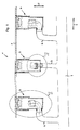
- a drainage system 1 has a drainage channel 3 formed in the longitudinal direction 2.
- the drainage system 1 is shown in a longitudinal section 2 cut side view.
- the gutter 3 is at the edge of a in the Fig. 1 not shown roadway arranged.
- the drainage system 1 has in the longitudinal direction 2 a plurality of spaced-apart drainage shafts 4.
- the downcomers 4 break through the gutter 3 and lead substantially in the vertical direction 5 in the ground.
- Each downcomer 4 is connected by means of a drain line 6 with a longitudinal direction 2 extending drainage line 7.
- A for example, due to a precipitate on the roadway accumulating liquid is passed through the gutter 3, the drain chutes 4 and the drain lines 6 to the drainage line 7 and discharged from this.
- Fig. 1 In this case, only a section of the gutter 3 with three downcomers 4 is shown.
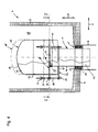
- Fig. 2 shows the first variant of the downcomer 4.
- the downcomer 4 is a downwardly from the gutter 3 from substantially in the vertical direction 5 downwardly extending and closed down cuboid hollow body.
- the hollow body has four side walls 8 and a bottom 9. He is poured from a concrete. On one of the side walls 8 near the bottom 9, a circular mouth opening 10 is arranged. In this mouth opening 10, the end of the drain line 6 is attached.
- the drain line 6 in turn leads to the drainage line 7, as shown in the Fig. 1 is shown.
- a drain pipe 11 opens.
- the drain pipe 11 is designed as a 90 ° elbow. It protrudes with its inlet end 12 in the vertical direction 5 into the downcomer 4.
- the outlet end 12 facing away from the drain end 13 opens with its outlet opening 13 'in the drain line 6.
- the drain pipe 11 is held with its furnishrohrau joint 14 of an inserted into the end of the drain line 6 annulus seal 15.
- the annular space seal 15 seals the annular space formed between the drain pipe outer casing 14 and the inside of the drainage pipe 11.
- the annular space seal 15 is fixed in position by means of clamping plates 16.
- a bell-shaped hood 18 is slipped.
- the hood 18 is designed as a hollow cylinder which is closed in the vertical direction 5 upwards by a top surface 19 designed as a dished bottom.
- At NASArohrauraumantel 14 is in the region of the inlet end 12 of the drain pipe 11 in the vertical direction 5 upwardly extending and the hood 18 at its free end by cross-retaining pin 20 is attached.
- the retaining bolt 20 connects via a wing nut 21, the hood 18 releasably connected to the inlet end 12. In this way, a spacing of the hood 18 to the inlet end 12 of the drain pipe 11 is reached.
- a drain gap 25 is formed both between a portion of the hood inner shell 22 and the Hurley dry condition 14 and between the inside 23 of the top surface 19 of the hood 18 and the opening edge 24 of the inlet opening 17.
- This outlet gap 25 has the geometry of an annular gap with a constant gap width in the area in which the hood 18 covers the downpipe 12.
- the interior of the downcomer 4 forms a fluid collection chamber 28.
- the fluid taken up by the fluid collection chamber 28 may also be a burning liquid such as gasoline, due to an accident occurring on the roadway in the downcomer 4 and thus in the Fluid collection chamber 28 enters.
- Coarse impurities contained in the fluid, such as leaves, stones or the like, are collected in the sludge bucket 27.
- the sludge bucket 27 also limits the amount of fluid flowing to the fluid collection chamber 28 per unit time.
- the fluid fills up the fluid collection chamber 28 up to the height of the opening edge 24 of the inlet opening 17 of the drainage pipe 11. If the liquid level of the fluid exceeds the height level of the opening edge 24, the fluid flows through the inlet opening 17 into the drainage pipe 11 and is led via the drainage line 6 to the drainage line 7.
- the fluid is not passed directly, but via the detour of the flow gap 25 in the drain pipe 11. Therefore, there are two effects.
- a discharge of the fluid takes place with a time delay only when the liquid level of the fluid is above the height level of the opening edge 24.
- particulate matter contained in the fluid which has passed through the recesses 26 of the sludge pail 27, settles on the bottom 9 of the downcomer 4 due to a slowing down of the flow velocity of the fluid. The suspended matter thus does not reach the drain line 6.
- the oxygen supply to the fluid is interrupted abruptly. If it is a burning fluid, the flame holding the fluid burning is safely smothered. In this way it is ensured that the burning fluid is not entered into the drain line 6. Rather, it comes at best to a local fire in the downcomer 4. An extension of the fire is thus effectively avoided.
- the sludge bucket 27 causes throttling and equalization of the amount of liquid supplied to the downcomer 4. This avoids a surge-like entry of the fluid into the outlet gap 25. Fire pockets trapped in air bubbles in the fluid can thus not enter the drainage pipe 6.
- the drain pipe 11 and the hood 18 can withstand fire, they are made of a heat-resistant stainless steel.
- This stainless steel is for example V4A.
- V4A is not only heat resistant, but also resistant to corrosion and aging.
- all other components, such as the retaining bolts 21 or the clamping plates 16, which may be exposed to fire, are advantageously made of such a stainless steel. All components can be pickled and passivated as additional protection.
- the wing nut 21 allows rapid disassembly of the hood 18 for inspection purposes or for flushing the drain pipe. 6
- Fig. 3 shows the downcomer according to arrow III in Fig. 2 seen again from the side of the drain pipe 6 ago. Also visible is a pipe flange 29, via which the drain line 6 can be screwed either to another pipe section of the drain line 6 or to the drainage line 7. This pipe flange 29 is in the Fig. 2 not shown.
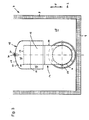
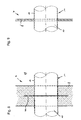
- Fig. 4 shows in a longitudinal section in the vertical direction 5, the second variant of the downcomer 4 from Fig. 1
- Fig. 5 shows the downcomer Fig. 4 in a cross section transverse to the vertical direction 5 according to the in Fig. 4 Plotted sectional plane VV.
- the Indian Fig. 1 to be seen upper portion of the downcomer with the Schlämmimer is in the Fig. 4 and 5 not shown.
- the functioning of the in the Fig. 4 and 5 Downstream well 4 essentially corresponds to the in the Fig. 2 and 3 illustrated variant. It is therefore only discussed the differences to this variant.
- the drain line 6 is arranged centrally in the bottom 9 of the downcomer 4 in a mouth opening 10.
- the drain pipe 11 is formed as a straight pipe piece extending in the vertical direction 5. It's like the drainpipe in the FIG. 2 and 3 held by an annulus seal 15 in the drain line 6 and sealed against it.
- the hood 18 is arranged opposite the drain pipe 11 in the vertical direction 5 movable. For this purpose, the hood 18 has on its outside three guide tabs 31 arranged in the radial direction 30. Furthermore, a stud holder 32 is attached to the inlet end 12 of the drain pipe 11 at readilyrohrauraumantel.
- the bolt holder 32 is embodied as a bolt circle welded onto the drain pipe outside jacket, which has three retaining tabs 34 projecting in the radial direction 30. At each retaining tab 34, a guide pin 35 is attached end. Each guide pin 35 passes through an inserted into a guide plate 31 recess in a guide sleeve inserted into the recess 36. At the vertically upward of the retaining tab 34 opposite side, each guide pin 35 held by a wing nut 21, pushed onto the guide pin 35 End stop 37 on. In the area of the guide lugs 31, a closure cover 38, which is designed as a circular disk and extends over the entire hood cross-section, is fastened to the hood inner casing 22.
- This closure cap 38 is in the closed position of the hood 18 on a on the opening edge 24 arranged around seal 40. As a result, it closes the inlet opening 17 and seals it.
- the seal 40 is designed as a plug-on rubber seal which receives the opening edge 24 in its interior.
- the hood 18 is lifted upwards in a vertical direction 5 by buoyancy according to the Archimedean principle, starting at a certain liquid level. If further fluid flows in, the hood 18 will be up to its in the Fig. 4 raised dashed opening position raised. This open position is predetermined by the three end stops 37 of the three guide pins 35.
- the hood 18 is raised in the vertical direction 5 and the closure cap 38 releases the inlet opening 17 of the drainage tube 6. The fluid drains below its burning surface. If the liquid level drops again, the hood 18 moves in the vertical direction 5 towards the bottom 9 of the downcomer 9. Of the Closure lid 38 closes the inlet opening 17 again. This ensures that no burning fluid enters the drainpipe 6.
- the variant with the movably mounted hood 18 is also suitable for a downcomer 4, which has no sludge bucket 27 upstream of the fluid collection chamber 28 for throttling the amount of liquid supplied to the fluid collection chamber 28.
- the inlet end 12 cross hood 18 also prevents coarse contaminants, such as branches or the like, between the cap 38 and the seal 40 are clamped and affect the sealing effect of the cap 38.
- the total of three wing nuts 21 allow easy disassembly of the hood 18 for maintenance purposes.
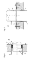
- Fig. 6 shows a side wall 8 of a downcomer 4, in which in a mouth opening 10, a drain line 6 is fixed. Both Fig. 6 to 9 is in each case the drain line 11 into the fluid interior 28 continued to think so that its inlet end 12 extends with the hood 18 arranged thereon in the vertical direction 5.
- a concentric annular space seal 15 is arranged, which is held by means of two executed as a bolted clamping plates in position at the end of the drain line 6.
- the drain pipe 11 is inserted with its discharge end 13 and fixed and held by the annulus seal 15.
- the annular space formed between the drain outside 14 of the drain pipe 11 and the inside of the drain line 11 is thus effectively sealed.
- a drain pipe 11 can be retrofitted with attached hood 18 in an existing downcomer.
- Fig. 7 shows a bottom 9 of a downcomer 4 with an inserted into a mouth opening 10 in the bottom 9 drain line 6.
- a drain pipe 11 is attached to the bottom 9.
- the attachment of the drain pipe 11 via a welded at its outlet end 13 on designingrohrau jointmantel 14 mounting flange 41.
- the mounting flange 41 is screwed by means of retaining dowels 42 to the bottom 9.
- a gap seal 43 is clamped between the mounting flange 41 and the bottom 9.
- a drain pipe 11 with a hood 18 arranged thereon can be retrofitted in an easy way into an existing downcomer.
- the gap seal 43 prevents at the material transition between the bottom 9 and drain line 6 caused by capillary leakage currents along the outer jacket of the drain line. 6
- Fig. 8 shows a side wall 8 of a downcomer 4, which is cast from concrete.
- the drain pipe 11 is poured into the side wall 8 and is held in a form-fitting manner by the surrounding side wall 8.
- the drain pipe 11 a circumferential wall ring 44 which is welded to the professionrohrauraumantel 14.
- the wall ring 44 prevents leakage currents, which could otherwise leave the fluid collection chamber 28 at the transition between theticianrohrau tomantel and the side wall 8 without being discharged through the drain line 6.
- the side walls 8 and the bottom 9 of the downcomer 4 can also be made of a steel.
- a stainless steel, such as V4A is suitable.
- the drain pipe 11 can be fixed in a simple manner in a recess introduced into the side wall 8 'by a weld seam along the outer jacket 14.
Abstract
Description
Die Erfindung betrifft ein Entwässerungssystem für eine Fläche oder Fahrbahn o. dgl. Bei derartigen Entwässerungssystemen besteht das sicherheitstechnische Problem, dass nach Unfällen oder Bränden brennende Flüssigkeiten in das Entwässerungssystem hineinfließen können und so einen punktuellen Brand weitertransportieren können, so dass sich dieser flächig ausbreitet.The invention relates to a drainage system for a surface or road o. The like. In such drainage systems, there is the safety problem that burning fluids can flow into the drainage system after accidents or fires and so can transport a punctual fire so that spreads this area.
Hiervon ausgehend liegt der Erfindung die Aufgabe zugrunde, ein Entwässerungssystem so zu gestalten, dass ein Ausbreiten eines punktuellen Brandes über das Entwässerungssystem wirksam verhindert wird. Diese Aufgabe ist durch die Merkmalskombination des Anspruchs 1 mit einfachen Mitteln in erfinderischer Weise gelöst. Die rückbezogenen Ansprüche beinhalten teilweise zweckmäßige und teilweise für sich selbst erfinderische Weiterbildungen der Erfindung.On this basis, the present invention seeks to design a drainage system so that a spread of a punctual fire on the drainage system is effectively prevented. This object is achieved by the combination of features of
Das erfindungsmäßige Entwässerungssystem besteht aus einer oder mehreren Entwässerungsleitungen. In jede dieser Leitungen münden in regelmäßigen oder unregelmäßigen Abständen Ablaufschächte ein. Insbesondere ist eine derartige Anordnung von Fahrbahnen bekannt, an welchen randseitig in gewissen Abständen Ablaufschächte angeordnet sind. Vor allem eignet sich die Erfindung zur brandgeschützten Entwässerung von Tunnelfahrbahnen, bei welchen die Entwässerungsleitungen aufgrund der strömungstechnischen Gegebenheiten im Tunnel brennende Fluide besonders schnell weiterleiten, so dass sich gerade in Tunnelanlagen Brände über die Entwässerungsleitungen ungewöhnlich schnell ausbreiten.The inventive drainage system consists of one or more drainage pipes. In each of these lines run-offs open at regular or irregular intervals. In particular, such an arrangement of roadways is known, on which edges at certain intervals drainage shafts are arranged. Above all, the invention is suitable for fire-protected drainage of tunnel lanes, in which the drainage lines due to the fluidic conditions in the tunnel burning fluids forward very quickly, so spread especially in tunnels fires on the drainage pipes unusually fast.
Die Lösung der Aufgabe besteht in einer konstruktiv sehr einfachen und deshalb erfinderischen Weiterbildung der Ablaufschächte. In jeden Ablaufschacht ist zunächst ein Ablaufrohr eingebracht. Dieses Ablaufrohr ragt mit seinem Zulaufende senkrecht in den Ablaufschacht hinein. Das dem Zulaufende abgewandte Ablaufende des Ablaufrohrs mündet in den Boden oder eine Seitenwand des Ablaufschachts. Das vertikal in den Ablaufschacht hineinragende Ablaufrohr bildet gleichsam ein Standrohr. Über die das Zulaufende abschließende Zulauföffnung des Ablaufrohres ist eine glockenförmige Haube gestülpt. Die übergestülpte Haube lässt hierbei sowohl einen radialen Spalt zwischen ihrem Haubeninnenmantel einerseits und dem Ablaufrohraußenmantel andererseits frei. Auch die Innenseite der Deckfläche der Haube liegt nicht auf dem Öffnungsrand der Zulauföffnung auf, sondern ist ebenfalls mit Abstand zum Öffnungsrand der Zulauföffnung angeordnet, um auch hier einen Ablaufspalt für das abzuleitende Fluid freizugeben.The solution to the problem consists in a structurally very simple and therefore inventive development of the downcomers. In each downcomer, a drain pipe is first introduced. This drain pipe protrudes with its inlet end vertically into the downcomer. The end of the drain pipe facing away from the inlet end opens into the bottom or a side wall of the downcomer. The vertical projecting into the downcomer drainpipe forms as it were a standpipe. About the inlet end of the inlet end of the drain pipe, a bell-shaped hood is slipped. The slipped hood leaves both a radial gap between their hood inner shell on the one hand and the Ablaufrohrauraußenmantel on the other hand free. Also, the inside of the top surface of the hood is not located on the opening edge of the inlet opening, but is also arranged at a distance from the opening edge of the inlet opening to release here also a drain gap for the fluid to be discharged.
Das abzuleitende Fluid läuft zunächst in den Ablaufschacht hinein und füllt diesen bis zur Höhe des Öffnungsrandes der Zulauföffnung des Ablaufrohrs. Erst wenn das Flüssigkeitsniveau des abzuleitenden Fluids das Höhenniveau des Öffnungsrands übersteigt, fließt das abzuleitende Fluid durch die Zulauföffnung in das Ablaufrohr hinein.The fluid to be discharged first runs into the downcomer and fills it up to the height of the opening edge of the inlet opening of the drainage pipe. Only when the liquid level of the fluid to be discharged exceeds the height level of the opening edge, the fluid to be discharged flows through the inlet opening into the drain pipe.
Aufgrund der auf das Ablaufrohr aufgesetzten glockenförmigen Haube fließt das Fluid nicht direkt in das Ablaufrohr hinein, sondern passiert zuvor den zwischen der Haube und dem Zulaufende des Ablaufrohrs gebildeten Ablaufspalt. Wird eine so große Fluidmenge in den Ablaufschacht eingeleitet, dass der momentane Fluidspiegel die Höhe des Ablaufrohrs überragt, wird das Fluid nach dem Gesetz der kommunizierenden Röhren sogar mit Überdruck durch den Ablaufspalt gleichsam gepumpt. Hierzu ist die Querschnittsfläche des Ablaufspaltes insbesondere so bemessen, dass sie gleich der oder größer als die freie Querschnittsfläche des Ablaufrohrs ist. Somit ist die über das Ablaufrohr abtransportierbare Flüssigkeitsmenge weiterhin von der Querschnittsfläche des Ablaufrohrs, nicht aber von der Querschnittsfläche des Ablaufspalts abhängig.Due to the patch on the outlet bell-shaped hood, the fluid does not flow directly into the drain pipe, but previously passed the drain gap formed between the hood and the inlet end of the drain pipe. If such a large amount of fluid introduced into the downcomer that the current fluid level projects beyond the height of the drain pipe, the fluid according to the law of communicating tubes is pumped even with overpressure through the flow gap as it were. For this purpose, the cross-sectional area of the drainage gap is dimensioned in particular such that it is equal to or greater than the free cross-sectional area of the drainage pipe. Thus, the amount of liquid that can be transported away via the discharge pipe continues to depend on the cross-sectional area of the discharge pipe, but not on the cross-sectional area of the discharge gap.
Während im Ablaufschacht eine ausreichende Sauerstoffmenge vorhanden ist, um ein brennendes Fluid am Brennen zu halten, wird infolge des von der Haube und dem Ablaufrohrmantel gebildeten, labyrinthartigen Ablaufspalts die Sauerstoffzufuhr zum Fluid abrupt unterbrochen. Aufgrund dieser abrupten Unterbrechung der Sauerstoffzufuhr wird die das Fluid am Brennen haltende Flamme erstickt. Ein Nachschub von Sauerstoff zur Aufrechterhaltung des Brennvorgangs vom Ablaufrohr her ist nicht möglich, da sich die Brenngase des brennenden Fluids in der Haube sammeln. Hierdurch baut sich ein leichter Überdruck in der Haube auf. Somit wird im Ablaufrohr aufsteigende kältere sauerstoffreiche Luft aufgrund eines Druckausgleichs in das Ablaufrohr zurück gedrängt.While a sufficient amount of oxygen is present in the downcomer to keep a burning fluid from burning, the supply of oxygen to the fluid is abruptly interrupted as a result of the labyrinthine outflow gap formed by the hood and the downcomer shell. Due to this abrupt interruption of the oxygen supply, the flame holding the fluid burning is stifled. A supply of oxygen to maintain the burning process from the drain pipe is not possible because the fuel gases of the burning fluid collect in the hood. As a result, a slight overpressure builds up in the hood. Thus, rising in the drain pipe colder oxygen-rich air is forced back into the drain pipe due to pressure equalization.
Das Fluid wird über die Entwässerungsleitung abgeführt, ohne weiter zu brennen. Infolge des Erstickens der Flamme wegen des fehlenden Sauerstoffs ist ein Ausbreiten des punktuellen Brandes durch das durch die Entwässerungsleitung durchgeleitete Fluid wirksam unterbunden.The fluid is discharged via the drainage line without burning further. As a result of the suffocation of the flame due to the lack of oxygen, a spreading of the punctual fire is effectively prevented by the fluid passed through the drainage line.
Mit der Erfindung ist es also möglich, das Ausbreiten eines Brandes über auslaufende brennende Flüssigkeiten wirksam zu verhindern. Eine Beschädigung der oftmals aus einem Kunststoff, insbesondere aus PVC, gefertigten Entwässerungsleitung ist somit sicher vermieden. Somit sind nach dem Auftreten eines punktuellen Brandes keine aufwändigen Sanierungsarbeiten zum Austausch oder zur Reparatur der Entwässerungsleitung notwendig. Durch den Abtransport von überschüssigem brennbaren Fluid ist zusätzlich die Dauer des punktuellen Brandes herabgesetzt, wenn ab einem bestimmten Zeitpunkt kein brennbares Fluid mehr nachströmt.With the invention it is thus possible to effectively prevent the spread of fire over leaking burning liquids. Damage to the often made of a plastic, in particular made of PVC, drainage pipe is thus safely avoided. Thus, after the occurrence of a punctual fire no costly renovation work to replace or repair the drainage pipe is necessary. Due to the removal of excess combustible fluid in addition, the duration of the punctual fire is reduced, if from a certain point no more flammable fluid flows.
Zusätzlich wirkt die Haubenaußenwand als Tauchwand. Mit anderen Worten können an der Fluidoberfläche schwimmende Verunreinigungen oder ein an Fluidoberfläche ausgebildeter Ölfilm nicht vom Ablaufspalt aus in das Ablaufrohr gelangen. Somit erfolgt eine grobe Vorreinigung des vom Ablaufrohr abgeführten Fluids.In addition, the hood outer wall acts as a baffle. In other words, impurities floating on the fluid surface or an oil film formed on the fluid surface can not enter the drainpipe from the drainage gap. Thus, a rough pre-cleaning of the discharged from the drain pipe fluid.
Die Erfindung eignet sich deshalb besonders zur Anwendung in Verkehrstunneln und Einhausungen sowie auf Betriebsflächen der Prozessindustrie, insbesondere der chemischen Industrie, der Raffinerien oder ähnliches.The invention is therefore particularly suitable for use in traffic tunnels and enclosures and on operating surfaces of the process industry, in particular the chemical industry, refineries or the like.
In einer typischen Ausführung weisen das Ablaufrohr einen Durchmesser von DN100 und die Haube einen Durchmesser von DN200 auf. Der Durchmesser der vom Ablaufschacht wegführenden Ablaufleitung liegt bei einem Durchmesser von DN150. Bei einem Ablaufschacht mit diesen Abmessungen liegt das Schluckvermögen bei etwa 15 I / s. Mit anderen Worten können pro Sekunde 15 I Fluid vom Ablaufschacht abgeleitet werden.In a typical design, the drainpipe has a diameter of DN100 and the hood has a diameter of DN200. The diameter of the drain pipe leading away drain pipe is at a diameter of DN150. With a downcomer of these dimensions, the swallowing capacity is about 15 l / s. In other words, 15 l of fluid can be diverted from the downcomer per second.
Nach der Lehre des Anspruchs 2 ist es vorteilhaft, den Ablaufspalt zwischen Haubeninnenmantel und Ablaufrohraußenmantel als umlaufenden Spalt mit vorzugsweise konstanter Spaltbreite auszugestalten. Auf diese Weise kann eine vergleichsweise große Fluidmenge abtransportiert werden unter Beibehaltung der Unterbrechung der Sauerstoffzufuhr im Ablaufspalt.According to the teaching of
Anspruch 3 betrifft eine Ausgestaltung der Erfindung mit einer Doppelfunktion der Haube. Bei dieser Ausführungsform ist die Haube gegenüber dem Ablaufrohr beweglich angeordnet. Die Haube ist auf diese Weise in vertikaler Richtung zwischen einer Öffnungsstellung und einer Schließstellung hin und her verschiebbar. Die Öffnungsstellung ist gegenüber der Funktionsstellung der starren Variante der Erfindung mit gegenüber dem Ablaufrohr ortsfest fixierter Haube unverändert. Zur Überführung in ihre Schließstellung wird die Haube in vertikaler Richtung am Ablaufrohr so weit in Richtung auf den Boden des Ablaufschachts bewegt, bis ein an der Innenseite der Haube angeordneter Verschlussdeckel oder die Deckfläche der Haube auf dem Öffnungsrand der Zulauföffnung fest aufliegt und die Zulauföffnung so fest verschließt. Um bei verschlossenem Ablaufrohr die selbsttätige Flüssigkeitsabfuhr zu gewährleisten, ist die Haube so ausgelegt, dass sie bei steigendem Flüssigkeitspegel im Ablaufschacht aufschwimmt. Damit wird der Ablaufspalt zwischen der Deckfläche der Haube und dem Öffnungsrand der Zulauföffnung wieder freigegeben, so dass das Fluid durch den Ablaufspalt ungehindert entweichen kann. Die Haube ist hierbei am Ablaufrohr derart gesichert, dass ein Aufschwimmen der Haube über die Öffnungsstellung hinaus, in welcher der Ablaufspalt vollständig freigegeben ist, wirksam unterbunden ist.
Das Fluid läuft unterhalb der brennenden Fluidoberfläche ab. Sinkt der Flüssigkeitspegel, so verschließt der am Haubeninnenmantel angeordnete Deckel die Zulauföffnung des Ablaufrohres wieder. Ein Eindringen von brennendem Fluid ist somit beim Absinken des Flüssigkeitspegels sicher vermieden.The fluid drains below the burning fluid surface. If the liquid level drops, the cover arranged on the hood inner shell closes the inlet opening of the drain pipe again. A penetration of burning fluid is thus safely avoided when the liquid level drops.
Die Ansprüche 4 und 5 betreffen zwei verschiedene Anordnungsmöglichkeiten des Ablaufrohrs im Ablaufschacht. Bei der Ausführungsform nach Anspruch 4 mündet das Ablaufrohr in den Boden des Ablaufschachts ein. Es handelt sich also um ein vertikal verlaufendes, streng zylindrisches Rohrstück. Die Ausgestaltung nach Anspruch 5 betrifft ein bogenförmiges Rohrstück, welches in eine Seitenwand des Ablaufschachts einmündet. Beide Varianten eignen sich gut zum Einstecken in vorhandene Ablaufleitungen im Boden oder einer Seitenwand des Ablaufschachts. Nach der Lehre des Anspruchs 6 ist schließlich der Ringraum zwischen dem Ablaufrohraußenmantel und der zugeordneten Einmündungsöffnung im Boden oder in der Seitenwand durch eine Ringraumdichtung zusätzlich abgesichert. Mit der Ringdichtung lassen sich auch Maßgenauigkeiten oder sonstige Toleranzfehler ausgleichen. Zur weiteren Sicherung der Ringraumdichtung an dieser Schnittstelle zwischen Ablaufrohr und der eigentlichen Entwässerungsleitung sind die zusätzlichen Klemmplatten nach Anspruch 7 vorgesehen.
Die Ansprüche 8 und 9 betreffen eine alternative Ausgestaltung der Fixierung der Ablaufrohre am Boden oder der Seitenwand des Ablaufschachts. Hierbei ist an das Ablaufrohr endseitig im Bereich der Auslauföffnung ein Montageflansch angeordnet. Mit Hilfe dieses Montageflansches kann das Abflussrohr entweder auf dem Boden oder an einer Seitenwand des Ablaufschachts mit mehreren Schrauben fixiert werden. In Weiterbildung ist nach Anspruch 9 vorgeschlagen, zwischen Montageflansch und den den Montageflansch haltenden Boden oder die den Montageflansch haltende Seitenwand eine Spaltdichtung zwischen zu schalten. Auch diese Variante verhindert ein ungewolltes Entweichen des Fluids außerhalb des Ablaufrohres.The
Die Varianten nach den Ansprüchen 4 bis 9 eigenen sich auch besonders gut zur Nachrüstung vorhandener Ablaufschächte mit der erfindungsmäßigen Brandschutzsicherung.The variants according to
In Anspruch 10 ist schließlich eine Variante zur Fixierung des Ablaufrohres im Boden oder einer Seitenwand des Ablaufschachts vorgeschlagen, bei welcher das Ablaufrohr in den Boden oder die Seitenwand formschlüssig eingebettet, insbesondere einbetoniert ist. Das formschlüssige Einbetten erfolgt bei der Fertigung bzw. Vorfertigung des Ablaufschachts. Bei der formschlüssigen Einformung des Ablaufrohrs in den Ablaufschacht ist es zweckmäßig, am Ablaufrohr einen umlaufenden Mauerring vorzusehen. Der umlaufende Mauerring springt nach Art einer umlaufenden Scheibe aus dem Ablaufrohraußenmantel radial hinaus. Diese radial abstehende Scheibe verhindert eine Bildung bzw. Aushöhlung eines Spalts zwischen dem Ablaufrohraußenmantel und dem das Ablaufrohr einbettenden Werkstoff, insbesondere Beton. Insbesondere aufgrund der Kapillarwirkung des Wassers kann es hin und wieder vorkommen, dass sich ungewollte Durchtrittskanäle zwischen dem Ablaufrohraußenmantel und dem das Ablaufrohr einbettenden Werkstoff bilden. Diese Kanalbildung ist aufgrund des als Sperrplatte wirkenden Mauerrings wirksam unterbunden.In
Anspruch 11 beinhaltet schließlich eine Ausführungsform der Erfindung mit einem in Ablaufrichtung dem Ablaufrohr vorgeschalteten Schlammeimer im Ablaufschacht. Ein derartiger Schlammeimer begünstigt die Reinhaltung des Ablaufschachts, weil Blätter, Schlamm und sonstige Verunreinigungen im Schlammeimer gesammelt werden. Zur Reinhaltung des Ablaufschachts muss der endseitige Rost vom Ablaufschacht abgehoben werden und sodann der Schlammeimer herausgehoben, entleert und gereinigt werden. Außerdem drosselt und vergleichmäßigt der Schlammeimer die dem Ablaufschacht zugeführte Flüssigkeitsmenge. Dadurch ist das Risiko einer starken Verwirbelung des Fluids vor dem Eintreten in den Ablaufspalt, verbunden mit dem möglichen Austrag eines lokalen Brandherds über den Ablaufspalt bis in das Ablaufrohr hinein, gering.
Bei dieser Ausführungsform sammelt sich stets eine gewisse Wassermenge zunächst im Schlammeimer, so dass der eigentliche Ablaufschacht innen trocken ist. Bei diesen Verhältnissen ist es dann wünschenswert, dass das Ablaufrohr mit Hilfe der Haube verschlossen ist. Die Haube hat dann auch die Funktion eines Geruchsverschlusses. Schließlich begünstigt die Erfindung auch die Reinhaltung des Ablaufschachts. Durch den Ablaufspalt können aufgrund der zweifachen Richtungsumkehr und der Herabsetzung der Strömungsgeschwindigkeit des Fluids Verunreinigungen im Fluid, insbesondere im Fluid enthaltene Schwebstoffe und Festkörper, nur in begrenztem Maße in das Ablaufrohr eindringen. Die Verunreinigungen lagern sich außerhalb des Ablaufrohrs am Boden des Ablaufschachts ab, wo sie problemlos abgeschöpft oder abgesaugt werden können.In this embodiment, a certain amount of water always collects in the sludge bucket, so that the actual downcomer is dry inside. In these conditions, it is then desirable that the drain pipe is closed by means of the hood. The hood then has the function of an odor trap. Finally, the invention also favors the cleanliness of the drainage shaft. Due to the flow gap can be due to the two-way reversal and the reduction of the flow velocity of the fluid Impurities in the fluid, particulate matter contained in the fluid and solids, penetrate only to a limited extent in the drain pipe. The impurities are deposited outside the drainpipe at the bottom of the downcomer, where they can easily be skimmed off or sucked off.
Anhand der nachfolgend aufgeführten Ausführungsbeispiele ist die Erfindung mit weiteren Vorteilen und Merkmalen weiter beschrieben. Es zeigen:
- Fig. 1
- ein Entwässerungssystem,
- Fig. 2
bis 3 - einen ersten Ablaufschacht,
- Fig. 4
bis 5 - einen zweiten Ablaufschacht,
- Fig. 6
- eine Seitenwand eines Ablaufschachtes,
- Fig. 7
- einen Boden eines weiteren Ablaufschachtes, sowie
- Fig. 8 bis 9
- die Seitenwände zweier weiterer Ablaufschächte.
- Fig. 1
- a drainage system,
- Fig. 2 to 3
- a first downcomer,
- 4 to 5
- a second downcomer,
- Fig. 6
- a side wall of a downcomer,
- Fig. 7
- a bottom of another downcomer, as well
- Fig. 8 to 9
- the side walls of two further downcomers.
Gemäß
In der
Über die das Zulaufende 12 abschließende Zulauföffnung 17 des Ablaufrohres 11 ist eine glockenförmige Haube 18 gestülpt. Die Haube 18 ist als Hohlzylinder ausgebildet, der in vertikaler Richtung 5 nach oben von einer als Klöpperboden ausgebildeten Deckfläche 19 abgeschlossen ist. Am Ablaufrohraußenmantel 14 ist im Bereich des Zulaufendes 12 des Ablaufrohres 11 ein sich in vertikaler Richtung 5 nach oben erstreckender und die Haube 18 an seinem Freiende durchgreifender Haltebolzen 20 befestigt. Der Haltebolzen 20 verbindet über eine Flügelmutter 21 die Haube 18 lösbar mit dem Zulaufende 12. Auf diese Weise ist eine Beabstandung der Haube 18 zum Zulaufende 12 des Ablaufrohres 11 erreicht. Dabei ist sowohl zwischen einem Teilbereich des Haubeninnenmantels 22 und des Ablaufrohraußenmantels 14 als auch zwischen der Innenseite 23 der Deckfläche 19 der Haube 18 und dem Öffnungsrand 24 der Zulauföffnung 17 ein Ablaufspalt 25 gebildet. Dieser Ablaufspalt 25 hat in dem Bereich, in dem die Haube 18 den Ablaufrohraußenmantel 14 überdeckt, die Geometrie eines Ringspaltes mit einer konstanten Spaltbreite.About the
Direkt unterhalb der Ablaufrinne 3 ist ein von Ausnehmungen 26 durchsetzter und den gesamten Querschnitt des Ablaufschachtes 4 versperrender Schlammeimer 27 angeordnet. Für die Ableitung eines Fluids bildet der Innenraum des Ablaufschachtes 4 einen Fluidsammelraum 28. Bei dem vom Fluidsammelraum 28 aufgenommenen Fluid kann es sich auch um eine brennende Flüssigkeit wie Benzin handeln, die infolge eines auf der Fahrbahn stattfindenden Unfalls in den Ablaufschacht 4 und somit in den Fluidsammelraum 28 eintritt. Grobe im Fluid enthaltene Verunreinigungen, wie Blätter, Steine oder dergleichen, werden im Schlammeimer 27 aufgefangen. Der Schlammeimer 27 begrenzt zugleich die Menge des Fluids, das dem Fluidsammelraum 28 pro Zeiteinheit zuströmt. Das Fluid füllt den Fluidsammelraum 28 bis zur Höhe des Öffnungsrandes 24 der Zulauföffnung 17 des Ablaufrohres 11 auf. Übersteigt das Flüssigkeitsniveau des Fluids das Höhenniveau des Öffnungsrandes 24, so fließt das Fluid durch die Zulauföffnung 17 in das Ablaufrohr 11 hinein und wird über die Ablaufleitung 6 zur Entwässerungsleitung 7 geleitet.Directly below the
Das Fluid wird nicht direkt, sondern über den Umweg des Ablaufspaltes 25 in das Ablaufrohr 11 geleitet. Daher ergeben sich zwei Effekte. Zum einen erfolgt eine Ableitung des Fluids mit einer zeitlichen Verzögerung erst dann, wenn das Flüssigkeitsniveau des Fluids über dem Höhenniveau des Öffnungsrandes 24 liegt. Hierdurch setzen sich im Fluid enthaltene Schwebstoffe, die die Ausnehmungen 26 des Schlammeimers 27 passiert haben, aufgrund einer Verlangsamung der Strömungsgeschwindigkeit des Fluids am Boden 9 des Ablaufschachtes 4 ab. Die Schwebstoff gelangen somit nicht in die Ablaufleitung 6.The fluid is not passed directly, but via the detour of the
Zum anderen wird im Ablaufspalt 25 die Sauerstoffzufuhr zum Fluid abrupt unterbrochen. Handelt es sich um ein brennendes Fluid, so wird die das Fluid am Brennen haltende Flamme sicher erstickt. Auf diese Weise ist gewährleistet, dass das brennende Fluid nicht in die Ablaufleitung 6 eingetragen wird. Vielmehr kommt es bestenfalls zu einem lokalen Brand im Ablaufschacht 4. Eine Ausweitung des Brandes ist somit wirkungsvoll vermieden.On the other hand, in the
Der Schlammeimer 27 bewirkt eine Drosselung und Vergleichmäßigung der dem Ablaufschacht 4 zugeführten Flüssigkeitsmenge. Damit ist ein schwallartiger Eintritt des Fluids in den Ablaufspalt 25 vermieden. In Luftblasen im Fluid eingeschlossene Brandnester können somit nicht in das Ablaufrohr 6 eintreten.The
Damit das Ablaufrohr 11 und die Haube 18 einem Brand widerstehen können, sind sie aus einem hitzebeständigen Edelstahl gefertigt. Bei diesem Edelstahl handelt es sich beispielsweise um V4A. V4A ist nicht nur hitzebeständig, sondern auch korrosions- und alterungsbeständig. Auch sämtliche anderen Bauteile, wie die Haltebolzen 21 oder die Klemmplatten 16, die einem Brand ausgesetzt sein können, sind vorteilhaft aus einem derartigen Edelstahl gefertigt. Sämtliche Bauteile können als zusätzlicher Schutz gebeizt und passiviert sein. Die Flügelmutter 21 gestattet eine schnelle Demontage der Haube 18 zu Revisionszwecken oder für ein Durchspülen des Ablaufrohrs 6.Thus, the
Die Ablaufleitung 6 ist mittig im Boden 9 des Ablaufschachtes 4 in einer Einmündungsöffnung 10 angeordnet. Das Ablaufrohr 11 ist als ein in vertikaler Richtung 5 verlaufendes gerades Rohrstück ausgebildet. Es ist wie das Ablaufrohr in den
Sammelt sich nun im Fluidsammelraum 28 Fluid an, so wird ab einem bestimmten Flüssigkeitspegel die Haube 18 durch Auftrieb nach dem archimedischen Prinzip in vertikaler Richtung 5 nach oben angehoben. Fließt weiteres Fluid nach, so wird die Haube 18 bis zu ihrer in der
Wird der Ablaufschacht 4 mit einem brennenden Fluid beaufschlagt, so wird die Haube 18 in vertikaler Richtung 5 angehoben und der Verschlussdeckel 38 gibt die Zulauföffnung 17 des Ablaufrohres 6 frei. Das Fluid läuft unterhalb seiner brennenden Oberfläche ab. Sinkt der Flüssigkeitspegel wieder, bewegt sich die Haube 18 in vertikaler Richtung 5 auf den Boden 9 des Ablaufschachts 9 zu. Der Verschlussdeckel 38 verschließt die Zulauföffnung 17 erneut. Damit ist sicher gestellt, dass kein brennendes Fluid in das Ablaufrohr 6 eindringt.If the
Da die Haube 18 für ein Ablaufen des Fluids zunächst mittels Auftrieb angehoben werden muss, ist der Ablauf des Fluids aus dem Fluidsammelraum 28 gegenüber dem in den
Die das Zulaufende 12 übergreifende Haube 18 verhindert außerdem, dass grobe Verunreinigungen, wie Geäst oder dergleichen, zwischen dem Verschlussdeckel 38 und der Dichtung 40 eingeklemmt werden und die abdichtende Wirkung des Verschlussdeckels 38 beeinträchtigen. Die insgesamt drei Flügelmuttern 21 gestatten eine einfache Demontage der Haube 18 zu Wartungszwecken.The
Im Inneren der Ablaufleitung 6 ist eine konzentrische Ringraumdichtung 15 angeordnet, die mittels zweier als Lochkreise ausgeführter Klemmplatten in ihrer Position am Ende der Ablaufleitung 6 gehalten ist. In diese Ringraumdichtung 15 ist das Ablaufrohr 11 mit seinem Ablaufende 13 eingeschoben und durch die Ringraumdichtung 15 fixiert und gehalten. Der zwischen der Ablaufaußenseite 14 des Ablaufrohres 11 und der Innenseite der Ablaufleitung 11 gebildete Ringraum ist somit wirksam abgedichtet. Mittels der Ringraumdichtung 15 lässt sich ein Ablaufrohr 11 mit aufgesetzter Haube 18 in einen bestehenden Ablaufschacht nachrüsten.Inside the
Gemäß
- 11
- Entwässerungssystemdrainage system
- 22
- Längsrichtunglongitudinal direction
- 33
- Ablaufrinnegutter
- 44
- Ablaufschachtdowncomer
- 55
- vertikale Richtungvertical direction
- 66
- Ablaufleitungdrain line
- 77
- Entwässerungsleitungdrain pipe
- 8,8'8,8 '
- SeitenwandSide wall
- 99
- Bodenground
- 1010
- Einmündungsöffnungentry port
- 1111
- Ablaufrohrdrain pipe
- 1212
- Zulaufendeinlet end
- 1313
- Ablaufendeexpiring
- 13'13 '
- Auslauföffnungoutlet opening
- 1414
- AblaufrohraußenmantelDrain pipe outer sheath
- 1515
- RingraumdichtungAnnulus seal
- 1616
- Klemmplatteclamp
- 1717
- Zulauföffnunginlet opening
- 1818
- HaubeHood
- 1919
- Deckflächecover surface
- 2020
- Haltebolzenretaining bolt
- 2121
- Flügelmutterbutterfly nut
- 2222
- HaubeninnenmantelHood inner jacket
- 2323
- Innenseiteinside
- 2424
- Öffnungsrandopening edge
- 2525
- Ablaufspaltdrain slit
- 2626
- Ausnehmungrecess
- 2727
- SchlammeimerSilt bucket
- 2828
- FluidsammelraumFluid collection space
- 2929
- Rohrflanschpipe flange
- 3030
- radiale Richtungradial direction
- 3131
- Führungslascheguide tab
- 3232
- Bolzenhalterungbolt bracket
- 3333
- LochkreisPCD
- 3434
- Haltelascheretaining tab
- 3535
- Führungsbolzenguide pins
- 3636
- Führungshülseguide sleeve
- 3737
- Endanschlagend stop
- 3838
- Verschlussdeckelcap
- 4040
- Dichtungpoetry
- 4141
- Montageflanschmounting flange
- 4242
- Haltedübeldowels
- 4343
- Spaltdichtunggap seals
- 4444
- Mauerringwall ring
Claims (12)
gekennzeichnet durch
marked by
dadurch gekennzeichnet,
dass das Ablaufrohr (11) und die Haube (18) aus einem hitzebeständigen Material gefertigt sind.Drainage system (1) according to claim 1,
characterized,
that the drain pipe (11) and the hood (18) are made of a heat-resistant material.
gekennzeichnet durch
einen radial umlaufenden Ablaufspalt (25) zwischen Haubeninnenmantel (22) und Ablaufrohraußenmantel (14) mit vorzugsweise konstanter Spaltbreite.Drainage system (1) according to claim 1 or 2,
marked by
a radially encircling outflow gap (25) between hood inner casing (22) and drainage outer casing (14) with preferably constant gap width.
gekennzeichnet durch
eine am Zulaufende (12) des Ablaufrohrs (11) vertikal beweglich gelagerte Haube (18), welche in ihrer Schließstellung mit einem am Haubeninnenmantel (22) befestigten Verschlussdeckel (38) auf dem Öffnungsrand (24) des Ablaufrohrs (11) aufliegt und welche in ihrer Öffnungsstellung den Ablaufspalt (25) zwischen der Innenseite (23) der Deckfläche (22) und dem Öffnungsrand (24) freigibt.Drainage system (1) according to one of claims 1 to 3,
marked by
at the inlet end (12) of the drain pipe (11) vertically movably mounted hood (18) in its closed position with a hood inner shell (22) fastened cover (38) on the opening edge (24) of the drain pipe (11) rests and which in their opening position the flow gap (25) between the inside (23) of the top surface (22) and the opening edge (24) releases.
gekennzeichnet durch
ein vertikales, in den Boden (9) des Ablaufschachts (4) einmündendes Ablaufrohr (11).Drainage system (1) according to one of claims 1 to 4,
marked by
a vertical, in the bottom (9) of the downcomer (4) opening outflow pipe (11).
gekennzeichnet durch
ein winkelförmiges, in eine Seitenwand (9) des Ablaufschachts (4) einmündendes Ablaufrohr (11).Drainage system (1) according to one of claims 1 to 5,
marked by
an angle-shaped, in a side wall (9) of the downcomer (4) opening outflow pipe (11).
gekennzeichnet durch
eine den Ringraum zwischen dem Ablaufrohraußenmantel (14) im Bereich der Auslauföffnung (13') und der Einmündung in den Boden (9) oder die Seitenwand (8) des Ablaufschachts (4) abdichtende Ringraumdichtung (15).Drainage system (1) according to one of claims 5 or 6,
marked by
an annular space seal (15) sealing the annular space between the downpipe outer casing (14) in the region of the outlet opening (13 ') and the mouth into the bottom (9) or the side wall (8) of the downcomer (4).
gekennzeichnet durch
zwischen die Einmündung für das Ablaufrohr (11) im Boden (9) oder in der Seitenwand (8) und den Ablaufrohraußenmantel (14) montierte, die Ringraumdichtung (15) fixierende Klemmplatten (16).Drainage system (1) according to one of claims 5 to 7,
marked by
between the junction for the drain pipe (11) in the bottom (9) or in the side wall (8) and the Ablaufrohraumantel (14) mounted, the annular space seal (15) fixing clamping plates (16).
gekennzeichnet durch
einen endseitig an der Auslauföffnung (13') des Ablaufrohrs (11) angeformten, auf den Boden (9) oder die Seitenwand (8) des Ablaufschachts (4) aufschraubbaren Montageflansch (41).Drainage system (1) according to one of claims 1 to 6,
marked by
one on the outlet opening (13 ') of the drain pipe (11) integrally formed, on the bottom (9) or the side wall (8) of the downcomer (4) aufschraubbaren mounting flange (41).
gekennzeichnet durch
eine zwischen dem Montageflansch (41) und dem Boden (9) oder der Seitenwand (8) des Ablaufschachts (4) angeordnete Spaltdichtung (43).Drainage system (1) according to claim 9,
marked by
a gap seal (43) arranged between the mounting flange (41) and the bottom (9) or the side wall (8) of the downcomer (4).
gekennzeichnet durch
ein in den Boden (9) oder die Seitenwand (8) des Ablaufschachts (4) eingebettetes, vorzugsweise einbetoniertes Auslaufende (13) des Ablaufrohres (11) mit einem radial vom Ablaufrohraußenmantel (14) abstehenden Mauerring (44) als Diffusionssperre.Drainage system (1) according to one of claims 1 to 6,
marked by
a in the bottom (9) or the side wall (8) of the downcomer (4) embedded, preferably concreted outlet end (13) of the drain pipe (11) with a radially from the Ablaufrohrauraumantel (14) protruding wall ring (44) as a diffusion barrier.
gekennzeichnet durch
einen dem Ablaufrohr (11) in Ablaufrichtung vorgeschalteten Schlammeimer (27) im Ablaufschacht (4).Drainage system (1) according to one of claims 1 to 11,
marked by
a drainage bucket (27) in the discharge shaft (4) upstream of the drainage pipe (11) in the direction of drainage.
Applications Claiming Priority (1)
| Application Number | Priority Date | Filing Date | Title |
|---|---|---|---|
| DE200720008019 DE202007008019U1 (en) | 2007-06-05 | 2007-06-05 | drainage system |
Publications (3)
| Publication Number | Publication Date |
|---|---|
| EP2000603A2 true EP2000603A2 (en) | 2008-12-10 |
| EP2000603A3 EP2000603A3 (en) | 2010-07-28 |
| EP2000603B1 EP2000603B1 (en) | 2015-04-29 |
Family
ID=39708729
Family Applications (1)
| Application Number | Title | Priority Date | Filing Date |
|---|---|---|---|
| EP20080009761 Not-in-force EP2000603B1 (en) | 2007-06-05 | 2008-05-29 | Drainage system |
Country Status (3)
| Country | Link |
|---|---|
| EP (1) | EP2000603B1 (en) |
| AT (1) | AT13081U1 (en) |
| DE (1) | DE202007008019U1 (en) |
Families Citing this family (3)
| Publication number | Priority date | Publication date | Assignee | Title |
|---|---|---|---|---|
| CZ306259B6 (en) * | 2014-01-24 | 2016-11-02 | Cs-Beton S.R.O. | Slotted pipe with dewatering system fire seal and use thereof |
| ES2555671B1 (en) * | 2014-07-04 | 2016-09-20 | Baroan Rioja, S.L. | Drain device with non-circular inlet hole |
| DE102018121292A1 (en) * | 2018-08-31 | 2020-03-05 | ACO Severin Ahlmann GmbH & Co Kommanditgesellschaft | Drainage shaft and drainage system |
Citations (6)
| Publication number | Priority date | Publication date | Assignee | Title |
|---|---|---|---|---|
| DE3639285A1 (en) * | 1986-11-18 | 1988-06-01 | Bernhard Kessel | Floor gulley |
| DE9317849U1 (en) * | 1993-11-23 | 1994-02-10 | Passavant Werke | Floor drain |
| GB2285460A (en) * | 1993-12-14 | 1995-07-12 | Harmer Holdings Ltd | Syphonic rainwater outlet |
| DE29606174U1 (en) * | 1996-04-03 | 1996-06-20 | Passavant Werke | Floor or ceiling drain with built-in odor trap |
| DE20200625U1 (en) * | 2001-12-12 | 2002-04-11 | Ahlmann Aco Severin | Fire protection procedure |
| EP1362961A1 (en) * | 2002-04-29 | 2003-11-19 | Dallmer GmbH & Co. KG | Structural unit for fire protection of a draining device and draining device comprising that structural unit |
Family Cites Families (3)
| Publication number | Priority date | Publication date | Assignee | Title |
|---|---|---|---|---|
| DE4015393A1 (en) * | 1990-05-14 | 1991-11-21 | Dallmer Gmbh & Co | Floor or roof-drain fitting - has plastics pot receiving outflow of water fitting inside larger steel pot and held by rubber ring |
| DE102004007454A1 (en) * | 2003-02-14 | 2004-08-26 | Dallmer Gmbh & Co. Kg | Runoff pot fire protection for buildings comprises protective mass dropped into pipe at excess temperature to protect mass from waste water and consequent loss of efficacy. |
| DE202004019658U1 (en) * | 2004-12-20 | 2005-02-17 | Basika Entwässerungen GmbH | Floor drain, especially for fireproof ceilings, comprises pan surrounded by coaxial dish with intermediate space filled with insulation material |
-
2007
- 2007-06-05 DE DE200720008019 patent/DE202007008019U1/en not_active Expired - Lifetime
-
2008
- 2008-05-29 AT ATGM168/2012U patent/AT13081U1/en not_active IP Right Cessation
- 2008-05-29 EP EP20080009761 patent/EP2000603B1/en not_active Not-in-force
Patent Citations (6)
| Publication number | Priority date | Publication date | Assignee | Title |
|---|---|---|---|---|
| DE3639285A1 (en) * | 1986-11-18 | 1988-06-01 | Bernhard Kessel | Floor gulley |
| DE9317849U1 (en) * | 1993-11-23 | 1994-02-10 | Passavant Werke | Floor drain |
| GB2285460A (en) * | 1993-12-14 | 1995-07-12 | Harmer Holdings Ltd | Syphonic rainwater outlet |
| DE29606174U1 (en) * | 1996-04-03 | 1996-06-20 | Passavant Werke | Floor or ceiling drain with built-in odor trap |
| DE20200625U1 (en) * | 2001-12-12 | 2002-04-11 | Ahlmann Aco Severin | Fire protection procedure |
| EP1362961A1 (en) * | 2002-04-29 | 2003-11-19 | Dallmer GmbH & Co. KG | Structural unit for fire protection of a draining device and draining device comprising that structural unit |
Also Published As
| Publication number | Publication date |
|---|---|
| EP2000603A3 (en) | 2010-07-28 |
| EP2000603B1 (en) | 2015-04-29 |
| AT13081U1 (en) | 2013-05-15 |
| DE202007008019U1 (en) | 2008-10-16 |
Similar Documents
| Publication | Publication Date | Title |
|---|---|---|
| EP2000603B1 (en) | Drainage system | |
| EP2508686B1 (en) | Retention assembly for precipitation and waste water | |
| EP2157252A2 (en) | Improved street or floor drain with retention device for light fluids | |
| DE102005016526B3 (en) | Shutting-off device for waste water control shaft has magnetic lock to hold blocking element after outflow in blocking position against inflow aperture | |
| DE102009048037B4 (en) | Filter device for roof drainage systems | |
| DE202012006401U1 (en) | Duct flusher for cleaning a drainage channel for rain or mixed water in a flushing shaft | |
| EP3074576A1 (en) | Drain device and inner pipe element for at least partial insertion into a drain insert of a drain device | |
| DE60201009T2 (en) | TWO-WAY TRAP | |
| CH658088A5 (en) | WASTEWATER DRAIN, CONSISING OF A DRAINAGE TANK WITH AT LEAST ONE INLET AND DRAIN PIPE AND USE THEREOF. | |
| EP3069773A2 (en) | Filter device for a conveyor system for conveying liquids containing wastes and/or solids | |
| EP2636812A1 (en) | Method and device for roof drainage in the form of a main drainage system and an emergency drainage system | |
| DE19608201C2 (en) | Seepage shaft for draining waste water into the ground | |
| DE202007011126U1 (en) | sedimentation | |
| DE10107496B4 (en) | Device for preventing gas leakage in a sewer manhole | |
| DE202005014237U1 (en) | Sedimentation plant, for the protection of waste water treatment systems, has a buried sedimentation body with a sedimentation zone with rotation of the inflow or the outflow | |
| AT412887B (en) | PIPE CLEANING DEVICE | |
| DE10320308B3 (en) | Rinsing device for an effluent channel has a lifting body attached to lifting arms in the region between both ends of a parallel lifting device | |
| EP1507045A1 (en) | Inlet in roads or floors with retaining device for light liquids | |
| DE2522425A1 (en) | ODOR TRAP FOR SEWER CONTAINER | |
| EP1394328A1 (en) | Check valve for drainage conduits | |
| DE2558642A1 (en) | Cleaning tube for sewage disposal system - has cover with non return valve and cover locking system | |
| DE2227419C3 (en) | Backflow stop for waste water | |
| DE202004012641U1 (en) | Drain for installation in roadway has perforated lid on cylindrical container with internal partitions and siphon pipe to take off water at bottom | |
| DE102012207200B4 (en) | Fire hydrant with stone trap | |
| DE102005017614A1 (en) | Separation assembly for water and lighter liquids e.g. oil has density-independent float mechanically linked to shut-off valve |
Legal Events
| Date | Code | Title | Description |
|---|---|---|---|
| PUAI | Public reference made under article 153(3) epc to a published international application that has entered the european phase |
Free format text: ORIGINAL CODE: 0009012 |
|
| AK | Designated contracting states |
Kind code of ref document: A2 Designated state(s): AT BE BG CH CY CZ DE DK EE ES FI FR GB GR HR HU IE IS IT LI LT LU LV MC MT NL NO PL PT RO SE SI SK TR |
|
| AX | Request for extension of the european patent |
Extension state: AL BA MK RS |
|
| RAP1 | Party data changed (applicant data changed or rights of an application transferred) |
Owner name: RAIMUNG HOELLEIN CAROLINENHUETTE GMBH |
|
| PUAL | Search report despatched |
Free format text: ORIGINAL CODE: 0009013 |
|
| AK | Designated contracting states |
Kind code of ref document: A3 Designated state(s): AT BE BG CH CY CZ DE DK EE ES FI FR GB GR HR HU IE IS IT LI LT LU LV MC MT NL NO PL PT RO SE SI SK TR |
|
| AX | Request for extension of the european patent |
Extension state: AL BA MK RS |
|
| 17P | Request for examination filed |
Effective date: 20110126 |
|
| AKX | Designation fees paid |
Designated state(s): AT BE BG CH CY CZ DE DK EE ES FI FR GB GR HR HU IE IS IT LI LT LU LV MC MT NL NO PL PT RO SE SI SK TR |
|
| 17Q | First examination report despatched |
Effective date: 20120529 |
|
| RAP1 | Party data changed (applicant data changed or rights of an application transferred) |
Owner name: HOELLKO GMBH |
|
| GRAP | Despatch of communication of intention to grant a patent |
Free format text: ORIGINAL CODE: EPIDOSNIGR1 |
|
| INTG | Intention to grant announced |
Effective date: 20141113 |
|
| GRAS | Grant fee paid |
Free format text: ORIGINAL CODE: EPIDOSNIGR3 |
|
| GRAA | (expected) grant |
Free format text: ORIGINAL CODE: 0009210 |
|
| AK | Designated contracting states |
Kind code of ref document: B1 Designated state(s): AT BE BG CH CY CZ DE DK EE ES FI FR GB GR HR HU IE IS IT LI LT LU LV MC MT NL NO PL PT RO SE SI SK TR |
|
| REG | Reference to a national code |
Ref country code: GB Ref legal event code: FG4D Free format text: NOT ENGLISH |
|
| REG | Reference to a national code |
Ref country code: CH Ref legal event code: EP |
|
| REG | Reference to a national code |
Ref country code: AT Ref legal event code: REF Ref document number: 724532 Country of ref document: AT Kind code of ref document: T Effective date: 20150515 |
|
| REG | Reference to a national code |
Ref country code: IE Ref legal event code: FG4D Free format text: LANGUAGE OF EP DOCUMENT: GERMAN |
|
| REG | Reference to a national code |
Ref country code: DE Ref legal event code: R096 Ref document number: 502008012928 Country of ref document: DE Effective date: 20150611 |
|
| REG | Reference to a national code |
Ref country code: NL Ref legal event code: VDEP Effective date: 20150429 |
|
| REG | Reference to a national code |
Ref country code: LT Ref legal event code: MG4D |
|
| PG25 | Lapsed in a contracting state [announced via postgrant information from national office to epo] |
Ref country code: NL Free format text: LAPSE BECAUSE OF FAILURE TO SUBMIT A TRANSLATION OF THE DESCRIPTION OR TO PAY THE FEE WITHIN THE PRESCRIBED TIME-LIMIT Effective date: 20150429 |
|
| PG25 | Lapsed in a contracting state [announced via postgrant information from national office to epo] |
Ref country code: NO Free format text: LAPSE BECAUSE OF FAILURE TO SUBMIT A TRANSLATION OF THE DESCRIPTION OR TO PAY THE FEE WITHIN THE PRESCRIBED TIME-LIMIT Effective date: 20150729 Ref country code: LT Free format text: LAPSE BECAUSE OF FAILURE TO SUBMIT A TRANSLATION OF THE DESCRIPTION OR TO PAY THE FEE WITHIN THE PRESCRIBED TIME-LIMIT Effective date: 20150429 Ref country code: ES Free format text: LAPSE BECAUSE OF FAILURE TO SUBMIT A TRANSLATION OF THE DESCRIPTION OR TO PAY THE FEE WITHIN THE PRESCRIBED TIME-LIMIT Effective date: 20150429 Ref country code: FI Free format text: LAPSE BECAUSE OF FAILURE TO SUBMIT A TRANSLATION OF THE DESCRIPTION OR TO PAY THE FEE WITHIN THE PRESCRIBED TIME-LIMIT Effective date: 20150429 Ref country code: HR Free format text: LAPSE BECAUSE OF FAILURE TO SUBMIT A TRANSLATION OF THE DESCRIPTION OR TO PAY THE FEE WITHIN THE PRESCRIBED TIME-LIMIT Effective date: 20150429 Ref country code: PT Free format text: LAPSE BECAUSE OF FAILURE TO SUBMIT A TRANSLATION OF THE DESCRIPTION OR TO PAY THE FEE WITHIN THE PRESCRIBED TIME-LIMIT Effective date: 20150831 |
|
| PG25 | Lapsed in a contracting state [announced via postgrant information from national office to epo] |
Ref country code: GR Free format text: LAPSE BECAUSE OF FAILURE TO SUBMIT A TRANSLATION OF THE DESCRIPTION OR TO PAY THE FEE WITHIN THE PRESCRIBED TIME-LIMIT Effective date: 20150730 Ref country code: IS Free format text: LAPSE BECAUSE OF FAILURE TO SUBMIT A TRANSLATION OF THE DESCRIPTION OR TO PAY THE FEE WITHIN THE PRESCRIBED TIME-LIMIT Effective date: 20150829 Ref country code: LV Free format text: LAPSE BECAUSE OF FAILURE TO SUBMIT A TRANSLATION OF THE DESCRIPTION OR TO PAY THE FEE WITHIN THE PRESCRIBED TIME-LIMIT Effective date: 20150429 |
|
| PG25 | Lapsed in a contracting state [announced via postgrant information from national office to epo] |
Ref country code: MC Free format text: LAPSE BECAUSE OF FAILURE TO SUBMIT A TRANSLATION OF THE DESCRIPTION OR TO PAY THE FEE WITHIN THE PRESCRIBED TIME-LIMIT Effective date: 20150429 Ref country code: IT Free format text: LAPSE BECAUSE OF FAILURE TO SUBMIT A TRANSLATION OF THE DESCRIPTION OR TO PAY THE FEE WITHIN THE PRESCRIBED TIME-LIMIT Effective date: 20150429 Ref country code: DK Free format text: LAPSE BECAUSE OF FAILURE TO SUBMIT A TRANSLATION OF THE DESCRIPTION OR TO PAY THE FEE WITHIN THE PRESCRIBED TIME-LIMIT Effective date: 20150429 Ref country code: EE Free format text: LAPSE BECAUSE OF FAILURE TO SUBMIT A TRANSLATION OF THE DESCRIPTION OR TO PAY THE FEE WITHIN THE PRESCRIBED TIME-LIMIT Effective date: 20150429 |
|
| REG | Reference to a national code |
Ref country code: DE Ref legal event code: R097 Ref document number: 502008012928 Country of ref document: DE |
|
| REG | Reference to a national code |
Ref country code: IE Ref legal event code: MM4A |
|
| PG25 | Lapsed in a contracting state [announced via postgrant information from national office to epo] |
Ref country code: SK Free format text: LAPSE BECAUSE OF FAILURE TO SUBMIT A TRANSLATION OF THE DESCRIPTION OR TO PAY THE FEE WITHIN THE PRESCRIBED TIME-LIMIT Effective date: 20150429 Ref country code: CZ Free format text: LAPSE BECAUSE OF FAILURE TO SUBMIT A TRANSLATION OF THE DESCRIPTION OR TO PAY THE FEE WITHIN THE PRESCRIBED TIME-LIMIT Effective date: 20150429 Ref country code: PL Free format text: LAPSE BECAUSE OF FAILURE TO SUBMIT A TRANSLATION OF THE DESCRIPTION OR TO PAY THE FEE WITHIN THE PRESCRIBED TIME-LIMIT Effective date: 20150429 Ref country code: RO Free format text: LAPSE BECAUSE OF NON-PAYMENT OF DUE FEES Effective date: 20150429 |
|
| PLBE | No opposition filed within time limit |
Free format text: ORIGINAL CODE: 0009261 |
|
| STAA | Information on the status of an ep patent application or granted ep patent |
Free format text: STATUS: NO OPPOSITION FILED WITHIN TIME LIMIT |
|
| GBPC | Gb: european patent ceased through non-payment of renewal fee |
Effective date: 20150729 |
|
| 26N | No opposition filed |
Effective date: 20160201 |
|
| REG | Reference to a national code |
Ref country code: FR Ref legal event code: ST Effective date: 20160311 |
|
| PG25 | Lapsed in a contracting state [announced via postgrant information from national office to epo] |
Ref country code: GB Free format text: LAPSE BECAUSE OF NON-PAYMENT OF DUE FEES Effective date: 20150729 Ref country code: IE Free format text: LAPSE BECAUSE OF NON-PAYMENT OF DUE FEES Effective date: 20150529 |
|
| PG25 | Lapsed in a contracting state [announced via postgrant information from national office to epo] |
Ref country code: SI Free format text: LAPSE BECAUSE OF FAILURE TO SUBMIT A TRANSLATION OF THE DESCRIPTION OR TO PAY THE FEE WITHIN THE PRESCRIBED TIME-LIMIT Effective date: 20150429 Ref country code: FR Free format text: LAPSE BECAUSE OF NON-PAYMENT OF DUE FEES Effective date: 20150629 |
|
| PGFP | Annual fee paid to national office [announced via postgrant information from national office to epo] |
Ref country code: CH Payment date: 20160526 Year of fee payment: 9 Ref country code: DE Payment date: 20160531 Year of fee payment: 9 |
|
| PGFP | Annual fee paid to national office [announced via postgrant information from national office to epo] |
Ref country code: AT Payment date: 20160519 Year of fee payment: 9 |
|
| PG25 | Lapsed in a contracting state [announced via postgrant information from national office to epo] |
Ref country code: MT Free format text: LAPSE BECAUSE OF FAILURE TO SUBMIT A TRANSLATION OF THE DESCRIPTION OR TO PAY THE FEE WITHIN THE PRESCRIBED TIME-LIMIT Effective date: 20150429 |
|
| PG25 | Lapsed in a contracting state [announced via postgrant information from national office to epo] |
Ref country code: BG Free format text: LAPSE BECAUSE OF FAILURE TO SUBMIT A TRANSLATION OF THE DESCRIPTION OR TO PAY THE FEE WITHIN THE PRESCRIBED TIME-LIMIT Effective date: 20150429 Ref country code: HU Free format text: LAPSE BECAUSE OF FAILURE TO SUBMIT A TRANSLATION OF THE DESCRIPTION OR TO PAY THE FEE WITHIN THE PRESCRIBED TIME-LIMIT; INVALID AB INITIO Effective date: 20080529 |
|
| PG25 | Lapsed in a contracting state [announced via postgrant information from national office to epo] |
Ref country code: CY Free format text: LAPSE BECAUSE OF FAILURE TO SUBMIT A TRANSLATION OF THE DESCRIPTION OR TO PAY THE FEE WITHIN THE PRESCRIBED TIME-LIMIT Effective date: 20150429 Ref country code: SE Free format text: LAPSE BECAUSE OF FAILURE TO SUBMIT A TRANSLATION OF THE DESCRIPTION OR TO PAY THE FEE WITHIN THE PRESCRIBED TIME-LIMIT Effective date: 20150429 |
|
| PG25 | Lapsed in a contracting state [announced via postgrant information from national office to epo] |
Ref country code: BE Free format text: LAPSE BECAUSE OF NON-PAYMENT OF DUE FEES Effective date: 20150531 |
|
| PG25 | Lapsed in a contracting state [announced via postgrant information from national office to epo] |
Ref country code: TR Free format text: LAPSE BECAUSE OF FAILURE TO SUBMIT A TRANSLATION OF THE DESCRIPTION OR TO PAY THE FEE WITHIN THE PRESCRIBED TIME-LIMIT Effective date: 20150429 |
|
| PG25 | Lapsed in a contracting state [announced via postgrant information from national office to epo] |
Ref country code: LU Free format text: LAPSE BECAUSE OF NON-PAYMENT OF DUE FEES Effective date: 20150529 |
|
| REG | Reference to a national code |
Ref country code: DE Ref legal event code: R119 Ref document number: 502008012928 Country of ref document: DE |
|
| REG | Reference to a national code |
Ref country code: CH Ref legal event code: PL |
|
| REG | Reference to a national code |
Ref country code: AT Ref legal event code: MM01 Ref document number: 724532 Country of ref document: AT Kind code of ref document: T Effective date: 20170529 |
|
| PG25 | Lapsed in a contracting state [announced via postgrant information from national office to epo] |
Ref country code: AT Free format text: LAPSE BECAUSE OF NON-PAYMENT OF DUE FEES Effective date: 20170529 |
|
| PG25 | Lapsed in a contracting state [announced via postgrant information from national office to epo] |
Ref country code: LI Free format text: LAPSE BECAUSE OF NON-PAYMENT OF DUE FEES Effective date: 20170531 Ref country code: CH Free format text: LAPSE BECAUSE OF NON-PAYMENT OF DUE FEES Effective date: 20170531 |
|
| PG25 | Lapsed in a contracting state [announced via postgrant information from national office to epo] |
Ref country code: DE Free format text: LAPSE BECAUSE OF NON-PAYMENT OF DUE FEES Effective date: 20171201 |