EP2000370B1 - Seitenairbageinheit mit Gehäuse mit Gasgenerator - Google Patents
Seitenairbageinheit mit Gehäuse mit Gasgenerator Download PDFInfo
- Publication number
- EP2000370B1 EP2000370B1 EP08104262A EP08104262A EP2000370B1 EP 2000370 B1 EP2000370 B1 EP 2000370B1 EP 08104262 A EP08104262 A EP 08104262A EP 08104262 A EP08104262 A EP 08104262A EP 2000370 B1 EP2000370 B1 EP 2000370B1
- Authority
- EP
- European Patent Office
- Prior art keywords
- housing
- sub
- inflator
- orifice
- airbag
- Prior art date
- Legal status (The legal status is an assumption and is not a legal conclusion. Google has not performed a legal analysis and makes no representation as to the accuracy of the status listed.)
- Not-in-force
Links
- 210000002445 nipple Anatomy 0.000 claims description 36
- 238000009434 installation Methods 0.000 claims description 8
- 239000011347 resin Substances 0.000 claims description 5
- 229920005989 resin Polymers 0.000 claims description 5
- 239000004744 fabric Substances 0.000 claims description 4
- 238000007789 sealing Methods 0.000 claims description 4
- 239000002184 metal Substances 0.000 claims description 3
- 238000000926 separation method Methods 0.000 description 11
- 230000000694 effects Effects 0.000 description 6
- 230000006378 damage Effects 0.000 description 3
- 230000003685 thermal hair damage Effects 0.000 description 3
- 230000002787 reinforcement Effects 0.000 description 2
- 125000006850 spacer group Chemical group 0.000 description 2
- 230000004913 activation Effects 0.000 description 1
- 230000015572 biosynthetic process Effects 0.000 description 1
- 230000000994 depressogenic effect Effects 0.000 description 1
- 239000000463 material Substances 0.000 description 1
- 230000001737 promoting effect Effects 0.000 description 1
- 230000001902 propagating effect Effects 0.000 description 1
- 230000035939 shock Effects 0.000 description 1
- 238000012795 verification Methods 0.000 description 1
Images


Classifications
-
- B—PERFORMING OPERATIONS; TRANSPORTING
- B60—VEHICLES IN GENERAL
- B60R—VEHICLES, VEHICLE FITTINGS, OR VEHICLE PARTS, NOT OTHERWISE PROVIDED FOR
- B60R21/00—Arrangements or fittings on vehicles for protecting or preventing injuries to occupants or pedestrians in case of accidents or other traffic risks
- B60R21/02—Occupant safety arrangements or fittings, e.g. crash pads
- B60R21/16—Inflatable occupant restraints or confinements designed to inflate upon impact or impending impact, e.g. air bags
- B60R21/20—Arrangements for storing inflatable members in their non-use or deflated condition; Arrangement or mounting of air bag modules or components
- B60R21/217—Inflation fluid source retainers, e.g. reaction canisters; Connection of bags, covers, diffusers or inflation fluid sources therewith or together
- B60R21/2171—Inflation fluid source retainers, e.g. reaction canisters; Connection of bags, covers, diffusers or inflation fluid sources therewith or together specially adapted for elongated cylindrical or bottle-like inflators with a symmetry axis perpendicular to the main direction of bag deployment, e.g. extruded reaction canisters
-
- B—PERFORMING OPERATIONS; TRANSPORTING
- B60—VEHICLES IN GENERAL
- B60R—VEHICLES, VEHICLE FITTINGS, OR VEHICLE PARTS, NOT OTHERWISE PROVIDED FOR
- B60R21/00—Arrangements or fittings on vehicles for protecting or preventing injuries to occupants or pedestrians in case of accidents or other traffic risks
- B60R21/02—Occupant safety arrangements or fittings, e.g. crash pads
- B60R21/16—Inflatable occupant restraints or confinements designed to inflate upon impact or impending impact, e.g. air bags
- B60R21/20—Arrangements for storing inflatable members in their non-use or deflated condition; Arrangement or mounting of air bag modules or components
- B60R21/207—Arrangements for storing inflatable members in their non-use or deflated condition; Arrangement or mounting of air bag modules or components in vehicle seats
Definitions
- the invention relates to an inflator-equipped housing for an airbag and a side airbag unit having the inflator-equipped housing structure for installation to the internal region of a seat in a vehicle.
- An airbag unit for use in a vehicle incorporates an airbag which deploys through inflation by the inflow of gas generated by an inflator.
- the inflator is attached to and secured by a housing to which the airbag is attached.
- the gas supplied by the inflator is guided into the airbag through the housing.
- the inflator normally has a cylindrical shape, and the housing is a normally a hollow cylinder with open ends.
- the inflator is inserted into the housing through one end and supported therein.
- the gas generated by the inflator flows along the length of the housing and enters the airbag from the open ends of the housing.
- the direction in which the inflated airbag deploys is extremely important for an airbag unit used in a vehicle. This is especially true for a side airbag unit because the airbag must inflate very rapidly into a narrow space between the person sitting in the seat and the side of the vehicle structure. It is possible to more securely set the direction of airbag deployment in a manner that the housing discharges gas toward the desired deploying direction.
- Gas discharged in the airbag deployment direction generates thrust to the inflator and housing in the opposite direction of the gas discharge direction.
- This thrust can pose a problem in regard to transportation and storage of the inflator before it is installed to the vehicle.
- the inflator is liable to be thermally damaged if exposed to fire or other heat source on transportation, or at the factory where it is made or at the vehicle assembly facility. If the inflator becomes thermally damaged, the gas may be accidentally discharged from the inflator and generate thrust which drives the inflator and housing through the air and thus cause it to become a dangerous projectile.
- Reference Document 1 describes an inflator, which is not attached to the housing but exists as a separate component.
- Reference Document 1 of " JIG FOR TRANSPORTING INFLATOR” describes a simple structure which has the purpose of preventing the inflator from becoming a projectile should it discharge the gas held therein during transportation as a result of thermal damage.
- a curved cover plate in which multiple leakage holes have been formed, is fixed to a cylindrical inflator by attachment bands to cover a discharge port which is formed on the inflator, and is spaced apart from the gas discharge port by spacers mounted on the inner surface of the cover plate to allow the part of gas flown from the gas discharge port to escape through the leakage holes.
- the present invention has been construed in light of the arforesaid shortcoming in the related art as a side airbag unit with inflator-equipping housing for installation to a vehicle wherein an inflator can be attached with a housing which discharges gas in a desired and specific direction where the airbag inflates and deploys, the thrust generated in a direction opposing the direction of the discharge gas flow can be suppressed should thermal damage to the inflator result in accidental gas discharge, and it can be properly ensured the normal operation capability of the side airbag unit.
- the inflator-equipped housing for airbag comprises a cylindrically hollow shaped metal sub-housing having an open gas discharge port at each end; a cylindrically shaped inflator inserted into the sub-housing through either gas discharge port and secured therein, the inflator having gas guide ports formed in its circumferential wall as means of guiding an airbag inflation gas there through; a 1st orifice in the sub-housing positioned in proximity to the gas guide ports and substantially facing an airbag deployment direction; a 2nd orifice in the sub-housing separated from the 1st orifice along an circumferential direction of the sub-housing; and a plug installed in and sealing the 2nd orifice; wherein the plug is of thermo-soluble resin, and includes a nipple part which has an external diameter dimensioned to contact with an internal periphery of the 2nd orifice and a flange part which extends from the nipple part and contacts with an internal surface of the sub-housing.
- the nipple part of the plug is inserted into the 2nd orifice from the internal side of the sub-housing and protrudes from the external surface of the sub-housing when the flange part is in contact with the internal surface of the sub-housing.
- a lip part is formed on the nipple part in order to prevent a removal of the nipple part from the 2nd orifice, and is located at a position outside of the external surface of the sub-housing when the flange part is in contact with the internal surface of the sub-housing by inserting the nipple part into the 2nd orifice from the internal side of the sub-housing so as to protrude it from the external surface of the sub-housing.
- protruding ribs are formed at appropriate locations on the interval surface of the sub-housing as means of securing the inflator within the sub-housing.
- the nipple part is formed to a substantially same cross section as the 2nd orifice, and the flange part is formed to a substantially same curvature as the inner surface of the sub-housing.
- the 2nd orifice is formed at a location opposite to and facing the 1st orifice.
- the present invention of the inflator-equipped housing for an airbag and side airbag unit therewith have the effects that an inflator can be attached with a housing which discharges gas in a desired and specific direction where the airbag inflates and deploys; the thrust generated in a direction opposing the direction of the discharge gas flow can be suppressed should thermal damage to the inflator result in accidental gas discharge; and it can be properly ensured the normal operation capability of the side airbag unit.
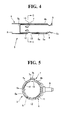
- FIG. 1 illustrates a side airbag unit 1 which is integrally installed to a seat back 2a of a vehicle seat 2, side airbag unit 1 primarily comprising an inflator-equipped housing 3, and a fabric airbag 4 residing within the housing 3 in a folded condition.
- an inflator 5 (to be described subsequently) of the side airbag unit 1 generates a gas which flows into the airbag 4 through a sub-housing 6, thus propagating the inflation and deployment of the airbag 4 toward the front of the vehicle from the side of the seat back 2a.
- the airbag 4 Upon activation of the side airbag unit 1, the airbag 4 begins to inflate while concurrently entering the narrow space between the person sitting in the seat 2 and the vehicle itself, and continues to inflate while moving toward the front of the vehicle along the side of the seat 2, thus protecting the person from the shock of the side impact.
- the inflator-equipped housing 3 includes the sub-housing 6, the inflator 5, and a plug 7.
- the sub-housing 6 is a hollow cylindrical metal structure of uniform thickness. While this embodiment describes the sub-housing 6 as a hollow cylinder, it may also be formed as a tube-like structure having angular walls. Both axial ends of the sub-housing 6 are open so as to form gas discharge ports 8.
- a mounting bolt 9 is installed near each end of the sub-housing 6, each mounting bold 9 protruding outward through the side of the sub-housing 6 in a radial direction. Threaded nuts (not shown in the drawings) are used to secure the mounting bolts 9 to the seat back 2a as means of attaching the sub-housing 6 to the seat back 2a.
- the cylindrically shaped inflator 5 resides within the sub-housing 6.
- the inflator 5 is cylindrical in shape so as to correspond to the hollow cylindrical space defined within the sub-housing 6.
- the inflator 5 may also be formed as a tube-like structure with angular walls if the sub-housing 6 were to be structured in the same configuration.
- the external diameter of the inflator 5 is formed to a slightly smaller dimension than the internal diameter of the sub-housing 6 so as to allow a small gap to exist there between.
- Multiple radially oriented gas guide ports 10 are formed at an appropriate position in the circumferential wall 5a of the inflator 5.
- the gas guide ports 10 are provided as means of directing the discharge of inflation gas into the airbag 4.
- the inflator 5 is axially aligned to and inserted into the sub-housing 6 from either gas discharge port 8 in a direction toward the opposing gas discharge port 8.
- the end part 5b of the inflator 5 may be inserted into the sub-housing 6 to an extent whereby the opposing end part 5c remains protruding from the sub-housing 6.
- the end part 5b may also be inserted up to the gas discharge port 8.
- the end part 5c of the inflator 5 may be enclosed by the sub-housing 6.
- Ribs 11 are formed at appropriate points on the inner surface 6a of the sub-housing 6, and protrude into the internal space of the sub-housing 6 as means of maintaining the inflator 5 at a specific location therein. Ribs 11 protrude a distance greater than the gap between the circumferential wall 5a of the inflator 5 and the inner surface 6a of the sub-housing 6.
- the ribs 11 are press-formed ridges extending the inside of the sub-housing 6 from the outside thereof.
- the ribs 11 may be formed by various manners.
- a 1st orifice 12 is formed in the wall of the sub-housing 6 in proximity to the gas guide port 10 in the inflator 5.
- the 1st orifice 12 faces the approximate direction of inflation of the airbag 4.
- the 1st orifice 12 faces the front of the vehicle from its position on the side of the seat 2.
- the gas generated by the inflator 5 flows through the gas guide ports 10 and is discharged from the gas discharge ports 8 through the gap between the sub-housing 6 and inflator 5, while concurrently flowing through the 1st orifice 12 in the inflation direction of the airbag 4.
- a 2nd orifice 13 is formed in the wall of the sub-housing 6 at a position along the radial circumference separated from the 1st orifice 12.
- the 2nd orifice 13 is formed to a smaller dimension than the 1st orifice 12, and may be provided in the form of a single orifice or multiple orifices. It is preferable that the 1st and 2nd orifices 12 and 13 are point symmetrical in relation to the axial center of the sub-housing 6, or linear symmetrical along a line at a right angle to the axial centerline of the sub-housing 6. In this embodiment, the 2nd orifice 13 is positioned directly across from the 1 st orifice 12 on the radial axis of the sub-housing 6.
- a plug 7 is installed to the 2nd orifice 13 from the internal side of the sub-housing 6.
- the plug 7 thus forms a seal which prevents gas from flowing out through the 2nd orifice 13.
- the plug 7 is a single structure primarily comprising a flange part 7a and a nipple part 7b integrally formed above the flange part 7a.
- the entire plug 7 is constructed of a heat fusibility resin which will soften and melt in a high heat environment such as that generated by a fire or other thermal source.
- the external diameter of the nipple part 7b is formed so as to stick in the inner periphery of the 2nd orifice 13.
- the external dimension of the nipple part 7b is made to the approximately same dimension as the 2nd orifice 13.
- the nipple part 7b is formed to a cross section shaped essentially the same as that of the 2nd orifice 13.
- the flange part 7a is formed as an approximately square plate-like structure which extends radially outward beneath the nipple part 7b.
- the flange part 7a has a curved surface which contacts the internal surface 6a of the sub-housing 6.
- the upper surface of the flange part 7a is formed to the same curved profile as that of the internal surface 6a of the sub-housing 6.
- the flange part 7a is made to a thickness approximately equivalent to that of the gap between the inflator 5 and the sub-housing 6.
- nipple part 7b is inserted into the 2nd orifice 13 from the internal side of the sub-housing 6, thus resulting in the upper surface of the flange part 7a coming into contact with the inner surface 6a of the sub-housing 6, and nipple part 7b extending above the external surface 6b of the sub-housing 6 to an extent shown by the letter 'H' in Fig. 7 .
- a lip part 7c is integrally formed to the nipple part 7b.
- the lip part 7c is inserted through the 2nd orifice 13 from the internal side of the sub-housing 6, and is separated from the sub-housing external surface 6b distance 'h' ( Fig. 7 ) when the upper surface of the flange part 7a is in contact with the sub-housing inner surface 6a.
- the lip part 7c is formed as a ring-shaped protrusion extending radially outward from the nipple part 7b.
- the lip part 7c engages the sub-housing external surface 6b to form a sandwich-like structure in which the lip part 7c and flange part 7a press oppositely against the sub-housing 6 to secure the plug 7 in place.
- the installation of the nipple part 7b into the 2nd orifice 13 is secure due to the plug 7 being made from resin.
- the side airbag unit 1 includes the inflator-equipped housing 3, fabric airbag 4, and an airbag case 14 which contains the airbag 4 and inflator-equipped housing 3.
- the airbag 4 the structure of which is well known in the art, is in a folded configuration with one extremity fixedly attached to the inflator 5 through the sub-housing 6.
- the one extremity of the airbag 4 is attached to the inflator-equipped housing 3 so as to completely envelope the gas discharge ports 8, 1 st orifice 12, and 2nd orifice 13.
- This structure allows all of the gas discharged from the inflator 5 to enter the airbag 4 through the sub-housing 6, and to inflate the folded airbag 4 to a fully deployed condition.
- the airbag case 14 is a box-like structure, made of a resin, which includes a cover flap 14a.
- the folded airbag 4 and the inflator-equipped housing 3 to which the airbag 4 is attached are inserted into the airbag case 14 through the open cover flap 14a.
- the sub-housing mounting bolts 9 extend outwards through holes formed in the cover flap 14a of the airbag case 14.
- Nuts 15 fasten to the mounting bolts 9 on the external side of the airbag case 14, and thus serve as means of securing the cover flap 14a in a closed condition while also securing the inflator-equipped housing 3 to the airbag case 14. As shown in the Fig.
- the inflator-equipped housing 3 is located in the upper region of the airbag case 14, while the folded airbag 4 is located in the lower region. Therefore, the 1st orifice 12, which faces toward the direction of the deployment of the airbag 4, is oriented downward.
- Separation line 16 is formed in the airbag case 14 at a location substantially opposing the 1st orifice 12. As illustrated in the Fig. 9 orientation, the separation line 16 is formed in an appropriate length on the bottom of the airbag case 14, in the lengthwise direction relative to the inflator-equipped housing 3, so as to oppose the 1st orifice 12.
- the separation line 16 may comprise a row of intermittent slits or notches, or a thin portion formed in the airbag case 14.
- the separation line 16 exists as a demarcation line in the airbag case 14 when the airbag 4 remains undeployed, but will become the line of separation along which the airbag case 14 ruptures to form deployment opening 17 by the inflation force when the airbag 4 is deployed.
- a hinge part 18 may be provided at the top of the airbag case 14 (relative to the view in Fig. 9 ) opposing to the separation line 16. While this embodiment describes the deployment opening 17 being formed from depressed parts along the separation line 16, other structures allowing the separation of the case 14 to be also employed. For example, a pre-formed slit or a hinged door-like structure provided adjacent to the opening is applicable as other means.
- the inflator-equipped housing 3 is handled as a separate component during transport, or stored as a separate component at the factory where it is manufactured or at the vehicle assembly site. Should the inflator-equipped housing 3 be damaged as a result of exposure to excessive heat in case of a fire and so on, the inflation gas will be directed through the gas guide port 10. At the same time, the heat will melt the plug 7 resulting in it being driven out of the 2nd orifice 13. To be specific, at least, the boundary portion between the flange part 7a and nipple part 7b will soften and break as a result of the excessive heat, thus leading to the destruction of the plug 7.
- the inflator 5 will reach its ignition point causing the generation and discharge of gas.
- the gas escaping from the gas guide port 10 will flow into and fill the gap between the sub-housing 6 and inflator 5, and then flow out of the sub-housing 6 through the 1st orifice 12 and the gas discharge ports 8.
- the pressure of the gas will drive the plug 7 out of the sub-housing 6 and thus open the 2nd orifice 13.
- the opened 2nd orifice 13 allows the escape of the gas there from, resulting in the generation of thrust in a direction counter to that generated by the escape of gas from the 1st orifice 12, thus canceling out a unidirectional thrust applied to the inflator 5.
- this structure makes it possible to counteract the thrust generated by the gas escaping from the 1st orifice 12 in the deployment direction of the airbag 4 by means of thrust generated by the gas escaping from the oppositely located 2nd orifice 13, and thus prevents a strong unidirectional thrust from being applied to the inflator-equipped housing 3.
- the thrust generated by the escape of gas from the 2nd orifice 13 counteracts and weakens the thrust generated by the gas escaping from the 1 st orifice 12.
- the thrust generated by gas escaping from the 2nd orifice 13 would have the effect of reducing the thrust generated by the gas escaping from the 1st orifice 12.
- Establishing the 2nd orifice 13 to a size slightly smaller than the 1st orifice 12 increases the sealing effect provided by the plug 7. It is preferable that the plug 7 may be made to smaller dimensions as it will hasten the thermal destruction speed at which the nipple part 7b and its surrounding part become thermally damaged and expose the 2nd orifice 13.
- the side airbag unit 1 which incorporates the inflator-equipped housing 3. It is preferable that the side airbag unit 1 is installed to a vehicle in an orientation wherein the airbag 4 will inflate in the region between the occupant and internal side of the vehicle while deploying toward the front of the vehicle.
- the inflator-equipped housing 3 is installed to the seat back 2a so that the 1st orifice 12 faces the front of the vehicle in the region between the occupant and internal side of the vehicle.
- the inflator-equipped housing 3 is placed in the airbag case 14, with the folded airbag 4 attached, before the installation to the vehicle.
- the airbag case 14 is then installed within the seat back 2a by secured with reinforcement in the seat back 2a of the seat 2. This is the finished configuration of the vehicular side airbag unit 1.
- gas generated by the inflator 5 flows into the airbag 4 from the gas guide port 10 through the sub-housing 6.
- the plug 7 remains seated in and sealing the 2nd orifice 13.
- Most of the gas generated by the inflator 5 flows out from the 1st orifice 12, while some gas also flows out of the gas discharge ports 8 in the sub-housing 6.
- the thrust generated by the gas flowing out of the 1st orifice 12 is received by the seat back 2a reinforcement, and the pressure of that gas is concentrated along the airbag 4 deployment direction due to the 1st orifice 12 facing the approximate deployment direction.
- the airbag 4 inflates and deploys efficiently in predominantly that direction from within the airbag case 14.
- the separation line 16 which is formed on the underside of the airbag case 14 and located substantially in opposition to the 1st orifice 12, ruptures by the pressure applied from the inflating airbag 4, thus creating the deployment opening 17 through which the airbag 4 may exit the airbag case 14.
- the airbag 4 then flies out of the airbag case 14, enters the space between the occupant sitting in the vehicle seat 2 and the internal side of the vehicle, and continues to deploy along the side of the vehicle seat 2 toward the front of the vehicle, and thus cushions the impact applied to the occupant.
- the side airbag unit 1 is thus able to offer a superior level of protection to the vehicle occupant.
- the nipple part 71b, 72b, or 73b may be established to a dimension in height whereby it at least protrudes from the external surface 6b of the sub-housing 6 when the flange part 71 a, 72a, or 73 a is in contact with the internal surface 6a of the sub-housing 6.
Landscapes
- Engineering & Computer Science (AREA)
- Mechanical Engineering (AREA)
- Air Bags (AREA)
Claims (7)
- Gehäuse mit Gasgenerator (3) für einen Airbag (4), umfassend:ein zylindrisch hohles Metall-Untergehäuse (6), das an jedem Ende eine offene Gasaustrittsöffnung (8) aufweist, wobeiein zylindrischer Gasgenerator (5) durch eine der Gasaustrittsöffnungen (8) in das Untergehäuse (6) eingesetzt ist und darin gesichert ist, wobei der Gasgenerator (5) Gasführungsöffnungen (10) aufweist, die in seiner umlaufenden Wand als Mittel zur Führung eines Airbag-Füllgases durch diese gebildet sind,eine erste Öffnung (12) im Untergehäuse (6), die in der Nähe von den Gasführungsöffnungen (10) angeordnet ist und im Wesentlichen einer Entfaltungsrichtung des Airbags (4) zugewandt ist,eine zweite Öffnung (13) im Untergehäuse (6), die entlang einer Umfangsrichtung des Untergehäuses (6) von der ersten Öffnung (12) getrennt ist undeinen Stopfen (7), der in die zweite Öffnung (13) eingebaut ist und diese abdichtet,wobei der Stopfen (7) aus hitzelöslichem Harz besteht und einen Nippelteil (7b) umfasst, der einen Außendurchmesser aufweist, der so bemessen ist, dass er mit einem inneren Umfang der zweiten Öffnung (13) in Kontakt tritt, und einen Flanschteil (7a), der sich vom Nippelteil (7b) erstreckt und der mit einer inneren Oberfläche (6a) des Untergehäuses (6) in Kontakt tritt.
- Gehäuse mit Gasgenerator (3) nach Anspruch 1, wobei der Nippelteil (7b) des Stopfens (7) von der inneren Seite des Untergehäuses (6) in die zweite Öffnung (13) eingesetzt ist und von der äußeren Oberfläche (6b) des Untergehäuses (6) hervorsteht, wenn sich der Flanschteil (7a) in Kontakt mit der inneren Oberfläche (6a) des Untergehäuses (6) befindet.
- Gehäuse mit Gasgenerator (3) nach Anspruch 1 oder 2, wobei ein Lippenteil (7c) am Nippelteil (7b) gebildet ist, um ein Entfernen des Nippelteils (7b) von der zweiten Öffnung (13) zu verhindern, und sich in einer Position außerhalb der äußeren Oberfläche (6b) des Untergehäuses (6) befindet, wenn sich der Flanschteil (7a) mit der inneren Oberfläche (6a) des Untergehäuses (6) durch Einführen des Nippelteils (7b) in die zweite Öffnung (13) von der inneren Seite des Untergehäuses (6) aus in Kontakt befindet, so dass es von der äußeren Oberfläche (6b) des Untergehäuses (6) hervorsteht.
- Gehäuse mit Gasgenerator (3) nach einem der Ansprüche 1 bis 3, wobei hervorstehende Rippen (11) an geeigneten Stellen auf der inneren Oberfläche (6a) des Untergehäuses (6) als Mittel zur Sicherung des Gasgenerators (5) innerhalb des Untergehäuses (6) gebildet sind.
- Gehäuse mit Gasgenerator (3) nach einem der Ansprüche 1 bis 4, wobei der Nippelteil (7b) mit einem im Wesentlichen gleichen Querschnitt wie die zweite Öffnung (13) gebildet ist und der Flanschteil (7a) mit einer im Wesentlichen gleichen Krümmung wie die innere Oberfläche (6a) des Untergehäuses (6) gebildet ist.
- Gehäuse mit Gasgenerator (3) nach einem der Ansprüche 1 bis 5, wobei die zweite Öffnung (13) in einer Position gegenüber der ersten Öffnung (12) und dieser zugewandt gebildet ist.
- Seitenairbageinheit (1) zum Einbau in einen Fahrzeugsitz (2), umfassend:ein Gehäuse mit Gasgenerator (3) für einen Airbag (4), der im Fahrzeugsitz (2) eingebaut ist, das Gehäuse mit Gasgenerator (3) nach einem der Ansprüche 1 bis 6,einen aufblasbaren Gewebeairbag (4), dessen eines Ende durch das Untergehäuse (6) in einer luftleeren, gefalteten Konfiguration am Gasgenerator (5) befestigt ist und sich im Wesentlichen in Richtung einer Vorderseite des Fahrzeuges von der Seite des Sitzes her aufbläst und entfaltet, wenn er mit einem vom Gasgenerator (5) generierten und durch das Untergehäuse (6) geführten Gas gefüllt wird, undeine Airbaghülle (14), in der der gefaltete Airbag (4) und das Gehäuse mit Gasgenerator (3) eingebaut sind, wobei die Airbaghülle (14) einen gegenüber der ersten Öffnung (12) im Untergehäuse (3) angeordneten Teil aufweist, der geöffnet werden kann, als Mittel zum Bereitstellen einer Öffnung (17) bei der Entfaltung des Airbags.
Applications Claiming Priority (1)
| Application Number | Priority Date | Filing Date | Title |
|---|---|---|---|
| JP2007151015A JP5154840B2 (ja) | 2007-06-06 | 2007-06-06 | インフレータ付きハウジングおよびこれを備えた車両用サイドエアバッグ装置 |
Publications (3)
| Publication Number | Publication Date |
|---|---|
| EP2000370A2 EP2000370A2 (de) | 2008-12-10 |
| EP2000370A3 EP2000370A3 (de) | 2012-03-28 |
| EP2000370B1 true EP2000370B1 (de) | 2013-02-13 |
Family
ID=39671744
Family Applications (1)
| Application Number | Title | Priority Date | Filing Date |
|---|---|---|---|
| EP08104262A Not-in-force EP2000370B1 (de) | 2007-06-06 | 2008-06-04 | Seitenairbageinheit mit Gehäuse mit Gasgenerator |
Country Status (2)
| Country | Link |
|---|---|
| EP (1) | EP2000370B1 (de) |
| JP (1) | JP5154840B2 (de) |
Families Citing this family (1)
| Publication number | Priority date | Publication date | Assignee | Title |
|---|---|---|---|---|
| JP6494105B2 (ja) * | 2015-08-06 | 2019-04-03 | 本田技研工業株式会社 | インフレータ及びエアバッグ装置 |
Family Cites Families (8)
| Publication number | Priority date | Publication date | Assignee | Title |
|---|---|---|---|---|
| US4964654A (en) * | 1989-05-11 | 1990-10-23 | Allied-Signal Inc. | Air bag assembly |
| DE9408908U1 (de) * | 1994-05-31 | 1994-11-17 | Trw Repa Gmbh | Gassack-Schutzvorrichtung |
| US5611563A (en) * | 1996-01-05 | 1997-03-18 | Morton International, Inc. | Airbag inflator attachment with snap-in sleeve |
| JPH1071904A (ja) * | 1996-08-30 | 1998-03-17 | Denso Corp | エアバッグ装置 |
| DE20313108U1 (de) * | 2002-08-20 | 2003-12-04 | Takata-Petri Ag | Airbagmodul mit Gasgenerator |
| JP4414248B2 (ja) * | 2004-02-24 | 2010-02-10 | 日本プラスト株式会社 | サイドエアバッグ装置 |
| DE102004055757B4 (de) * | 2004-11-18 | 2007-01-04 | Autoliv Development Ab | Gassackeinheit |
| DE202005008847U1 (de) * | 2005-06-03 | 2005-10-06 | Autoliv Development Ab | Gasgeneratoreinheit |
-
2007
- 2007-06-06 JP JP2007151015A patent/JP5154840B2/ja not_active Expired - Fee Related
-
2008
- 2008-06-04 EP EP08104262A patent/EP2000370B1/de not_active Not-in-force
Also Published As
| Publication number | Publication date |
|---|---|
| JP2008302785A (ja) | 2008-12-18 |
| JP5154840B2 (ja) | 2013-02-27 |
| EP2000370A2 (de) | 2008-12-10 |
| EP2000370A3 (de) | 2012-03-28 |
Similar Documents
| Publication | Publication Date | Title |
|---|---|---|
| US7152875B2 (en) | Air bag system | |
| JP5607246B2 (ja) | 自動車用のエアーバッグモジュール | |
| US9387822B2 (en) | Airbag device | |
| JP2664353B2 (ja) | ガスバッグ保護装置 | |
| US7040655B2 (en) | Airbag apparatus | |
| US6695344B2 (en) | Airbag module | |
| US6364342B1 (en) | Retainer ring having air deflector and airbag mounting structure using the same | |
| JP2002524353A (ja) | エアーバッグモジュール | |
| US6494483B2 (en) | Airbag module | |
| US8480126B2 (en) | Airbag | |
| EP2000370B1 (de) | Seitenairbageinheit mit Gehäuse mit Gasgenerator | |
| CN1142871C (zh) | 带有包括部分排放区域的气体引导壳体的气囊装置 | |
| JPH1059109A (ja) | ガスバッグモジュール | |
| KR20010114138A (ko) | 에어백 | |
| JP6100126B2 (ja) | エアバッグ装置 | |
| US6217067B1 (en) | Flame protection for a gas bag | |
| EP2776289B1 (de) | Schubneutrale gasgenerator-anordnung | |
| JP5378890B2 (ja) | エアバッグ装置 | |
| JP5873313B2 (ja) | リテーナ構造 | |
| US7731234B2 (en) | Air bag module with diffuser | |
| KR101263034B1 (ko) | 에어백 조립체 | |
| KR100538511B1 (ko) | 듀얼 스테이지 에어백 모듈 | |
| KR100538510B1 (ko) | 멀티 스테이지 에어백 시스템 | |
| KR20240157415A (ko) | 에어백 쿠션 프로텍터 | |
| JP2009196466A (ja) | エアバック装置 |
Legal Events
| Date | Code | Title | Description |
|---|---|---|---|
| PUAI | Public reference made under article 153(3) epc to a published international application that has entered the european phase |
Free format text: ORIGINAL CODE: 0009012 |
|
| AK | Designated contracting states |
Kind code of ref document: A2 Designated state(s): AT BE BG CH CY CZ DE DK EE ES FI FR GB GR HR HU IE IS IT LI LT LU LV MC MT NL NO PL PT RO SE SI SK TR |
|
| AX | Request for extension of the european patent |
Extension state: AL BA MK RS |
|
| PUAL | Search report despatched |
Free format text: ORIGINAL CODE: 0009013 |
|
| AK | Designated contracting states |
Kind code of ref document: A3 Designated state(s): AT BE BG CH CY CZ DE DK EE ES FI FR GB GR HR HU IE IS IT LI LT LU LV MC MT NL NO PL PT RO SE SI SK TR |
|
| AX | Request for extension of the european patent |
Extension state: AL BA MK RS |
|
| RIC1 | Information provided on ipc code assigned before grant |
Ipc: B60R 21/217 20110101AFI20120223BHEP |
|
| 17P | Request for examination filed |
Effective date: 20120524 |
|
| GRAP | Despatch of communication of intention to grant a patent |
Free format text: ORIGINAL CODE: EPIDOSNIGR1 |
|
| AKX | Designation fees paid |
Designated state(s): AT BE BG CH CY CZ DE DK EE ES FI FR GB GR HR HU IE IS IT LI LT LU LV MC MT NL NO PL PT RO SE SI SK TR |
|
| GRAS | Grant fee paid |
Free format text: ORIGINAL CODE: EPIDOSNIGR3 |
|
| GRAA | (expected) grant |
Free format text: ORIGINAL CODE: 0009210 |
|
| AK | Designated contracting states |
Kind code of ref document: B1 Designated state(s): AT BE BG CH CY CZ DE DK EE ES FI FR GB GR HR HU IE IS IT LI LT LU LV MC MT NL NO PL PT RO SE SI SK TR |
|
| REG | Reference to a national code |
Ref country code: GB Ref legal event code: FG4D |
|
| REG | Reference to a national code |
Ref country code: AT Ref legal event code: REF Ref document number: 596292 Country of ref document: AT Kind code of ref document: T Effective date: 20130215 |
|
| REG | Reference to a national code |
Ref country code: IE Ref legal event code: FG4D |
|
| REG | Reference to a national code |
Ref country code: DE Ref legal event code: R096 Ref document number: 602008022053 Country of ref document: DE Effective date: 20130411 |
|
| REG | Reference to a national code |
Ref country code: AT Ref legal event code: MK05 Ref document number: 596292 Country of ref document: AT Kind code of ref document: T Effective date: 20130213 |
|
| REG | Reference to a national code |
Ref country code: NL Ref legal event code: VDEP Effective date: 20130213 |
|
| REG | Reference to a national code |
Ref country code: LT Ref legal event code: MG4D |
|
| PG25 | Lapsed in a contracting state [announced via postgrant information from national office to epo] |
Ref country code: SE Free format text: LAPSE BECAUSE OF FAILURE TO SUBMIT A TRANSLATION OF THE DESCRIPTION OR TO PAY THE FEE WITHIN THE PRESCRIBED TIME-LIMIT Effective date: 20130213 Ref country code: BG Free format text: LAPSE BECAUSE OF FAILURE TO SUBMIT A TRANSLATION OF THE DESCRIPTION OR TO PAY THE FEE WITHIN THE PRESCRIBED TIME-LIMIT Effective date: 20130513 Ref country code: ES Free format text: LAPSE BECAUSE OF FAILURE TO SUBMIT A TRANSLATION OF THE DESCRIPTION OR TO PAY THE FEE WITHIN THE PRESCRIBED TIME-LIMIT Effective date: 20130524 Ref country code: NO Free format text: LAPSE BECAUSE OF FAILURE TO SUBMIT A TRANSLATION OF THE DESCRIPTION OR TO PAY THE FEE WITHIN THE PRESCRIBED TIME-LIMIT Effective date: 20130513 Ref country code: LT Free format text: LAPSE BECAUSE OF FAILURE TO SUBMIT A TRANSLATION OF THE DESCRIPTION OR TO PAY THE FEE WITHIN THE PRESCRIBED TIME-LIMIT Effective date: 20130213 Ref country code: AT Free format text: LAPSE BECAUSE OF FAILURE TO SUBMIT A TRANSLATION OF THE DESCRIPTION OR TO PAY THE FEE WITHIN THE PRESCRIBED TIME-LIMIT Effective date: 20130213 Ref country code: IS Free format text: LAPSE BECAUSE OF FAILURE TO SUBMIT A TRANSLATION OF THE DESCRIPTION OR TO PAY THE FEE WITHIN THE PRESCRIBED TIME-LIMIT Effective date: 20130613 |
|
| PG25 | Lapsed in a contracting state [announced via postgrant information from national office to epo] |
Ref country code: LV Free format text: LAPSE BECAUSE OF FAILURE TO SUBMIT A TRANSLATION OF THE DESCRIPTION OR TO PAY THE FEE WITHIN THE PRESCRIBED TIME-LIMIT Effective date: 20130213 Ref country code: FI Free format text: LAPSE BECAUSE OF FAILURE TO SUBMIT A TRANSLATION OF THE DESCRIPTION OR TO PAY THE FEE WITHIN THE PRESCRIBED TIME-LIMIT Effective date: 20130213 Ref country code: BE Free format text: LAPSE BECAUSE OF FAILURE TO SUBMIT A TRANSLATION OF THE DESCRIPTION OR TO PAY THE FEE WITHIN THE PRESCRIBED TIME-LIMIT Effective date: 20130213 Ref country code: PL Free format text: LAPSE BECAUSE OF FAILURE TO SUBMIT A TRANSLATION OF THE DESCRIPTION OR TO PAY THE FEE WITHIN THE PRESCRIBED TIME-LIMIT Effective date: 20130213 Ref country code: GR Free format text: LAPSE BECAUSE OF FAILURE TO SUBMIT A TRANSLATION OF THE DESCRIPTION OR TO PAY THE FEE WITHIN THE PRESCRIBED TIME-LIMIT Effective date: 20130514 Ref country code: PT Free format text: LAPSE BECAUSE OF FAILURE TO SUBMIT A TRANSLATION OF THE DESCRIPTION OR TO PAY THE FEE WITHIN THE PRESCRIBED TIME-LIMIT Effective date: 20130613 Ref country code: SI Free format text: LAPSE BECAUSE OF FAILURE TO SUBMIT A TRANSLATION OF THE DESCRIPTION OR TO PAY THE FEE WITHIN THE PRESCRIBED TIME-LIMIT Effective date: 20130213 |
|
| PG25 | Lapsed in a contracting state [announced via postgrant information from national office to epo] |
Ref country code: HR Free format text: LAPSE BECAUSE OF FAILURE TO SUBMIT A TRANSLATION OF THE DESCRIPTION OR TO PAY THE FEE WITHIN THE PRESCRIBED TIME-LIMIT Effective date: 20130213 |
|
| PG25 | Lapsed in a contracting state [announced via postgrant information from national office to epo] |
Ref country code: DK Free format text: LAPSE BECAUSE OF FAILURE TO SUBMIT A TRANSLATION OF THE DESCRIPTION OR TO PAY THE FEE WITHIN THE PRESCRIBED TIME-LIMIT Effective date: 20130213 Ref country code: CZ Free format text: LAPSE BECAUSE OF FAILURE TO SUBMIT A TRANSLATION OF THE DESCRIPTION OR TO PAY THE FEE WITHIN THE PRESCRIBED TIME-LIMIT Effective date: 20130213 Ref country code: EE Free format text: LAPSE BECAUSE OF FAILURE TO SUBMIT A TRANSLATION OF THE DESCRIPTION OR TO PAY THE FEE WITHIN THE PRESCRIBED TIME-LIMIT Effective date: 20130213 Ref country code: NL Free format text: LAPSE BECAUSE OF FAILURE TO SUBMIT A TRANSLATION OF THE DESCRIPTION OR TO PAY THE FEE WITHIN THE PRESCRIBED TIME-LIMIT Effective date: 20130213 Ref country code: SK Free format text: LAPSE BECAUSE OF FAILURE TO SUBMIT A TRANSLATION OF THE DESCRIPTION OR TO PAY THE FEE WITHIN THE PRESCRIBED TIME-LIMIT Effective date: 20130213 Ref country code: RO Free format text: LAPSE BECAUSE OF FAILURE TO SUBMIT A TRANSLATION OF THE DESCRIPTION OR TO PAY THE FEE WITHIN THE PRESCRIBED TIME-LIMIT Effective date: 20130213 |
|
| PLBE | No opposition filed within time limit |
Free format text: ORIGINAL CODE: 0009261 |
|
| STAA | Information on the status of an ep patent application or granted ep patent |
Free format text: STATUS: NO OPPOSITION FILED WITHIN TIME LIMIT |
|
| PG25 | Lapsed in a contracting state [announced via postgrant information from national office to epo] |
Ref country code: IT Free format text: LAPSE BECAUSE OF FAILURE TO SUBMIT A TRANSLATION OF THE DESCRIPTION OR TO PAY THE FEE WITHIN THE PRESCRIBED TIME-LIMIT Effective date: 20130213 |
|
| 26N | No opposition filed |
Effective date: 20131114 |
|
| PG25 | Lapsed in a contracting state [announced via postgrant information from national office to epo] |
Ref country code: MC Free format text: LAPSE BECAUSE OF FAILURE TO SUBMIT A TRANSLATION OF THE DESCRIPTION OR TO PAY THE FEE WITHIN THE PRESCRIBED TIME-LIMIT Effective date: 20130213 |
|
| REG | Reference to a national code |
Ref country code: CH Ref legal event code: PL |
|
| REG | Reference to a national code |
Ref country code: DE Ref legal event code: R097 Ref document number: 602008022053 Country of ref document: DE Effective date: 20131114 |
|
| REG | Reference to a national code |
Ref country code: IE Ref legal event code: MM4A |
|
| PG25 | Lapsed in a contracting state [announced via postgrant information from national office to epo] |
Ref country code: CH Free format text: LAPSE BECAUSE OF NON-PAYMENT OF DUE FEES Effective date: 20130630 Ref country code: IE Free format text: LAPSE BECAUSE OF NON-PAYMENT OF DUE FEES Effective date: 20130604 Ref country code: LI Free format text: LAPSE BECAUSE OF NON-PAYMENT OF DUE FEES Effective date: 20130630 |
|
| PG25 | Lapsed in a contracting state [announced via postgrant information from national office to epo] |
Ref country code: MT Free format text: LAPSE BECAUSE OF FAILURE TO SUBMIT A TRANSLATION OF THE DESCRIPTION OR TO PAY THE FEE WITHIN THE PRESCRIBED TIME-LIMIT Effective date: 20130213 |
|
| PG25 | Lapsed in a contracting state [announced via postgrant information from national office to epo] |
Ref country code: TR Free format text: LAPSE BECAUSE OF FAILURE TO SUBMIT A TRANSLATION OF THE DESCRIPTION OR TO PAY THE FEE WITHIN THE PRESCRIBED TIME-LIMIT Effective date: 20130213 Ref country code: CY Free format text: LAPSE BECAUSE OF FAILURE TO SUBMIT A TRANSLATION OF THE DESCRIPTION OR TO PAY THE FEE WITHIN THE PRESCRIBED TIME-LIMIT Effective date: 20130213 |
|
| PG25 | Lapsed in a contracting state [announced via postgrant information from national office to epo] |
Ref country code: HU Free format text: LAPSE BECAUSE OF FAILURE TO SUBMIT A TRANSLATION OF THE DESCRIPTION OR TO PAY THE FEE WITHIN THE PRESCRIBED TIME-LIMIT; INVALID AB INITIO Effective date: 20080604 Ref country code: LU Free format text: LAPSE BECAUSE OF NON-PAYMENT OF DUE FEES Effective date: 20130604 |
|
| REG | Reference to a national code |
Ref country code: FR Ref legal event code: PLFP Year of fee payment: 9 |
|
| REG | Reference to a national code |
Ref country code: FR Ref legal event code: PLFP Year of fee payment: 10 |
|
| REG | Reference to a national code |
Ref country code: FR Ref legal event code: PLFP Year of fee payment: 11 |
|
| PGFP | Annual fee paid to national office [announced via postgrant information from national office to epo] |
Ref country code: FR Payment date: 20190627 Year of fee payment: 12 |
|
| PGFP | Annual fee paid to national office [announced via postgrant information from national office to epo] |
Ref country code: GB Payment date: 20190628 Year of fee payment: 12 Ref country code: DE Payment date: 20190628 Year of fee payment: 12 |
|
| REG | Reference to a national code |
Ref country code: DE Ref legal event code: R119 Ref document number: 602008022053 Country of ref document: DE |
|
| GBPC | Gb: european patent ceased through non-payment of renewal fee |
Effective date: 20200604 |
|
| PG25 | Lapsed in a contracting state [announced via postgrant information from national office to epo] |
Ref country code: FR Free format text: LAPSE BECAUSE OF NON-PAYMENT OF DUE FEES Effective date: 20200630 Ref country code: GB Free format text: LAPSE BECAUSE OF NON-PAYMENT OF DUE FEES Effective date: 20200604 |
|
| PG25 | Lapsed in a contracting state [announced via postgrant information from national office to epo] |
Ref country code: DE Free format text: LAPSE BECAUSE OF NON-PAYMENT OF DUE FEES Effective date: 20210101 |