EP2000227A2 - Vorrichtung und verfahren zur korrektur von metallrohrenden - Google Patents
Vorrichtung und verfahren zur korrektur von metallrohrenden Download PDFInfo
- Publication number
- EP2000227A2 EP2000227A2 EP07740117A EP07740117A EP2000227A2 EP 2000227 A2 EP2000227 A2 EP 2000227A2 EP 07740117 A EP07740117 A EP 07740117A EP 07740117 A EP07740117 A EP 07740117A EP 2000227 A2 EP2000227 A2 EP 2000227A2
- Authority
- EP
- European Patent Office
- Prior art keywords
- pipe
- plug
- outer diameter
- taper portion
- diameter
- Prior art date
- Legal status (The legal status is an assumption and is not a legal conclusion. Google has not performed a legal analysis and makes no representation as to the accuracy of the status listed.)
- Granted
Links
Images


Classifications
-
- B—PERFORMING OPERATIONS; TRANSPORTING
- B21—MECHANICAL METAL-WORKING WITHOUT ESSENTIALLY REMOVING MATERIAL; PUNCHING METAL
- B21D—WORKING OR PROCESSING OF SHEET METAL OR METAL TUBES, RODS OR PROFILES WITHOUT ESSENTIALLY REMOVING MATERIAL; PUNCHING METAL
- B21D39/00—Application of procedures in order to connect objects or parts, e.g. coating with sheet metal otherwise than by plating; Tube expanders
- B21D39/08—Tube expanders
- B21D39/20—Tube expanders with mandrels, e.g. expandable
-
- B—PERFORMING OPERATIONS; TRANSPORTING
- B21—MECHANICAL METAL-WORKING WITHOUT ESSENTIALLY REMOVING MATERIAL; PUNCHING METAL
- B21D—WORKING OR PROCESSING OF SHEET METAL OR METAL TUBES, RODS OR PROFILES WITHOUT ESSENTIALLY REMOVING MATERIAL; PUNCHING METAL
- B21D3/00—Straightening or restoring form of metal rods, metal tubes, metal profiles, or specific articles made therefrom, whether or not in combination with sheet metal parts
- B21D3/14—Recontouring
-
- B—PERFORMING OPERATIONS; TRANSPORTING
- B21—MECHANICAL METAL-WORKING WITHOUT ESSENTIALLY REMOVING MATERIAL; PUNCHING METAL
- B21D—WORKING OR PROCESSING OF SHEET METAL OR METAL TUBES, RODS OR PROFILES WITHOUT ESSENTIALLY REMOVING MATERIAL; PUNCHING METAL
- B21D41/00—Application of procedures in order to alter the diameter of tube ends
- B21D41/02—Enlarging
- B21D41/026—Enlarging by means of mandrels
Definitions
- the present invention relates to an apparatus used for sizing the inner diameter of the end of a pipe such as a seamless pipe or a welded pipe, and a sizing method thereof.
- a known method for improving the inner diameter precision of a pipe end is that the pipe end is being expanded and sized by using an expanding apparatus.
- Fig. 4 is a schematic drawing that explains a sizing method for the pipe end by using a conventional expanding apparatus.
- a plug 5, connected to a cylinder 4 is moved in a direction indicated by an arrow in the Figure.
- the plug 5 is shoved to a predetermined position into the end of the pipe 1 so that the inner diameter of the pipe end is sized.
- the plug 5 is moved in a direction indicated by another arrow in the Figure, and drawn from the pipe 1.
- the plug to be used in the conventional expanding apparatus has a circular cross section, and is constituted by a taper portion and a diameter equivalent portion.
- the taper portion is a portion whose diameter gradually expands from the tip of the plug in the axial direction toward the rear end (from the left end to the right end in the Figure), and the diameter equivalent portion is a portion whose diameter is not varied.
- the taper angle of the taper portion is kept constant.
- Patent Document 1 JP2001-113329A
- the pipe obtained by the above-mentioned conventional pipe end sizing method tends to have variability in its inner diameter in a circumferential direction or an axis direction. The reason for this is explained below.
- Fig. 5 is a schematic drawing that explains problems with the conventional pipe end sizing method.
- the pipe 1 is expanded in its diameter by the plug 5 so that the inner diameter becomes from Din to D10.
- a phenomenon hereinafter, referred to as "overshoot" occurs in that the inner diameter D10 of the pipe 1 becomes larger than the outer diameter D1 of the diameter equivalent portion 52.
- the overshoot is made to occur before the inner diameter of the pipe end has been expanded by the plug to the target inner diameter, and is then completed.
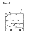
- the inventers of the present invention proposed a plug as shown in Figs. 1 to 3 in Japan Patent Application No. 2004-273836 in order to solve the above-mentioned problems.
- a plug 3, shown in Fig. 1 has a circular cross section, and is constituted by a taper portion 31 and a diameter equivalent portion 3 that are continuously formed from the tip of the plug in succession, and the outer diameter of the taper portion 31 expands from the tip toward the rear end while satisfying the following formulas (1) and (2). 22 ⁇ LR / ( D ⁇ 1 ⁇ 0.01 / 2 ) ⁇ 115 R ⁇ 2 ⁇ R ⁇ 1
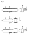
- Fig. 2 upon sizing the inner diameter of the pipe 1 end by using this plug 3, first, as shown in Fig. 2(a) , the plug 3 connected to the cylinder 4 is moved in a direction indicated by an arrow in the Figure, with the pipe 1 being clamped by a chuck 2. Moreover, as shown in Fig. 2(b) , the plug 3 is shoved into the pipe 1 end to a predetermined position so as to size the inner diameter of the pipe end. Thereafter, as shown in Fig. 2(c) , the plug 3 is moved in a direction indicated by another arrow in the Figure to be drawn from the pipe 1.
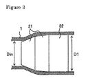
- the inner diameter is sized by diameter-expanding the pipe 1 by the use of this plug 3, as shown in Fig. 3 , since the overshoot of the pipe 1, generated at the taper portion 31, is completed inside the taper portion 31, the inner face of the pipe 1 is made in contact with the diameter equivalent portion 32. For this reason, variability in the inner diameter is reduced smaller so that the inner diameter of the pipe 1 end can be sized, with its true circle state being maintained.
- the inner face of the pipe is made in contact not only with the taper portion, but also with the diameter equivalent portion so that the contact area increases, resulting in an increase in a load to be used for sizing the inner diameter of the pipe end. Consequently, the clamping force by the chuck 2 needs to be increased.
- the pipe In the case of a pipe with a certain measure of thickness, no adverse effects are given to the shape or the like of the pipe, even when the clamping force increases; however, in the case of a thin material that is insufficient in rigidity (with the ratio (t/D) of the thickness t and the outer diameter D of the pipe being 0.04 or less), the pipe is deformed by the clamping force. The resulting deformation causes degradation in the dimensional precision in the inner diameter of the end (that is, the end to be diameter-expanded) of the pipe. Therefore, the clamping position needs to be appropriately set depending on the dimension of the pipe.
- the present invention has been devised from these points of view, and its objective is to provide a pipe end sizing apparatus and a pipe end sizing method that produces a pipe that is superior in the dimensional precision in the inner diameter of the pipe end.
- the present invention relates to a pipe end sizing apparatus shown in the following (A) and a pipe end sizing method shown in the following (B) and (C).
- the inner diameter of the pipe end can be sized with superior dimensional precision.
- a pipe end sizing apparatus in accordance with the present invention is provided with, for example, a plug 3 inserted into the pipe 1 end, a chuck 2 used for clamping a pipe and a shifting means (not shown) for shifting the plug 3 and/or the chuck 2.
- the plug 3 to be used in the pipe end sizing apparatus of the present invention has a circular cross section, and is constituted by a taper portion 31 and a diameter equivalent portion 32 continuously formed from the tip of the plug in succession, with the outer diameter of the taper portion 31 gradually expanding from the tip toward the rear end while satisfying the following formulas (1) and (2). 22 ⁇ LR / ( D ⁇ 1 ⁇ 0.01 / 2 ) ⁇ 115 R ⁇ 2 ⁇ R ⁇ 1 Where the meanings of the respective symbols in the formulas are shown below:
- the taper angle R2 at the position in which the outer diameter of the taper portion 31 is represented by D1 ⁇ 0.99 (hereinafter, referred to as "D2") is greater than the taper angle R1 at the rear end of the taper portion 31, and since the distance LR in the axial direction from the rear end of the taper portion to the position at which the outer diameter is represented by D2 satisfies the above-mentioned formula (1), the pipe 1 is hardly subjected to a bending process on the rear end side from the position at which the outer diameter of the taper portion 31 is represented by D2.
- the pipe 1 end can be sized in its inner diameter, with variations in the inner diameter being kept small and with its true circle state being maintained.
- the apparatus for the pipe end sizing in accordance with the present invention is characterized in that the position in which the pipe 1 is clamped by the chuck 2, that is, the distance from the pipe end of the pipe 1 on the side from which the plug 3 is inserted to the clamped position by the chuck 2 can be altered.
- the clamped position refers to the portion of the chuck closest to the pipe end.
- the pipe end sizing apparatus of the present invention allows the clamping position of the pipe to be altered so that, when a thick-wall material is sized, a portion closer to the pipe end is clamped, while, when a thin-wall material is sized, a portion far apart from the pipe end is clamped.
- the clamping position of the pipe by the chuck is set in accordance with the value of a ratio (t/D) of the thickness t and the outer diameter D of the pipe.
- the pipe is preferably clamped by the chuck at a position that satisfies the following formula (3).
- the reason for having to provide such a condition as to satisfy the following formula (3) with respect to the clamping position of the pipe by the chuck will be explained in Examples. L / D > 21.8 ⁇ ( t / D ) + 1.7 Where, the meanings of the respective symbols in the formula are shown below:
- a plug as shown in Fig. 1 , was inserted into the end of a seamless steel pipe made of carbon steel so that the pipe was diameter-expanded and the elliptic rate of the inner diameter of the pipe after having been diameter-expanded was examined.
- Table 1 shows the outer diameter and the wall thickness of each of pipes subjected to the experiments, as well as the shapes of the plugs, clamped positions and the elliptic rate of the inner diameter.
- the elliptic rate of inner diameter is maintained at 0.3, which is a low value, even when L/D is near 0.9; however, in the case of a thin pipe in which t/D is 0.020, the elliptic rate of inner diameter is varied depending on the value of L/D. This indicates that depending on the value of t/D, the distance from the pipe end which a plug is inserted to the clamped position by the chuck needs to be adjusted.
- L/D in the case when t/D of the element pipe is 0.04 or less, in order to set L/D so that the elliptic rate of inner diameter becomes 0.3 %, L/D should be located within the range that satisfy the following formula (3).
- the inner diameter of a pipe end can be sized with superior dimensional precision; therefore, the present invention is effectively applied to a sizing process for joint portions of line pipes, oil pipes and the like.
Landscapes
- Engineering & Computer Science (AREA)
- Mechanical Engineering (AREA)
- Metal Extraction Processes (AREA)
- Clamps And Clips (AREA)
Applications Claiming Priority (2)
| Application Number | Priority Date | Filing Date | Title |
|---|---|---|---|
| JP2006088487A JP5050382B2 (ja) | 2006-03-28 | 2006-03-28 | 金属管端矯正方法 |
| PCT/JP2007/056679 WO2007114176A1 (ja) | 2006-03-28 | 2007-03-28 | 金属管端矯正設備および金属管端矯正方法 |
Publications (4)
| Publication Number | Publication Date |
|---|---|
| EP2000227A2 true EP2000227A2 (de) | 2008-12-10 |
| EP2000227A9 EP2000227A9 (de) | 2009-04-08 |
| EP2000227A4 EP2000227A4 (de) | 2013-11-13 |
| EP2000227B1 EP2000227B1 (de) | 2016-10-12 |
Family
ID=38563444
Family Applications (1)
| Application Number | Title | Priority Date | Filing Date |
|---|---|---|---|
| EP07740117.2A Ceased EP2000227B1 (de) | 2006-03-28 | 2007-03-28 | Verfahren zur korrektur von metallrohrenden |
Country Status (7)
| Country | Link |
|---|---|
| US (1) | US7788957B2 (de) |
| EP (1) | EP2000227B1 (de) |
| JP (1) | JP5050382B2 (de) |
| CN (1) | CN101410199B (de) |
| CA (1) | CA2645932C (de) |
| MX (1) | MX2008012237A (de) |
| WO (1) | WO2007114176A1 (de) |
Cited By (1)
| Publication number | Priority date | Publication date | Assignee | Title |
|---|---|---|---|---|
| WO2016159932A1 (en) * | 2015-03-27 | 2016-10-06 | Cummins Inc. | Ovalized rotary forged fuel systems accumulator |
Families Citing this family (9)
| Publication number | Priority date | Publication date | Assignee | Title |
|---|---|---|---|---|
| JP5012304B2 (ja) * | 2007-08-10 | 2012-08-29 | 住友金属工業株式会社 | 冷間引抜加工用プラグ及び金属管の製造方法 |
| EP2676747B1 (de) | 2011-02-15 | 2019-04-03 | Nippon Steel & Sumitomo Metal Corporation | Verfahren zur korrektur von rohrenden eines nahtlosen rohrs aus einem edelstahl mit hohem cr-anteil |
| DE102013206577A1 (de) * | 2013-04-12 | 2014-10-16 | Peri Gmbh | Verfahren zur Festigung und Kalibrierung eines Rohrabschnittes |
| PL3344406T3 (pl) | 2015-09-01 | 2023-02-06 | Belvac Production Machinery, Inc. | Sposób i urządzenie do roztłaczania puszki |
| CN105268771A (zh) * | 2015-10-29 | 2016-01-27 | 西安航空动力股份有限公司 | 一种空心薄壁铸件的矫正装置及其矫正方法 |
| US10052672B1 (en) * | 2017-05-03 | 2018-08-21 | Brian Boudwin | Copper pipe bending tool |
| CN107583971A (zh) * | 2017-10-17 | 2018-01-16 | 柳州北斗星液压科技有限公司 | 一种可用于钢圈精整圆的装置 |
| CN110560518B (zh) * | 2019-07-11 | 2024-11-05 | 西安成立航空制造有限公司 | 一种三维管路组件氩弧焊后校型方法 |
| CN116251904B (zh) * | 2023-01-31 | 2026-01-23 | 一重集团大连核电石化有限公司 | 一种裂口圈结构及液压胀装置 |
Family Cites Families (10)
| Publication number | Priority date | Publication date | Assignee | Title |
|---|---|---|---|---|
| US4161112A (en) * | 1978-02-21 | 1979-07-17 | The Babcock & Wilcox Company | Tube drawing technique |
| JPS6224827A (ja) * | 1985-07-25 | 1987-02-02 | Sumitomo Metal Ind Ltd | 拡管用マンドレル |
| JPS63183738A (ja) * | 1987-01-26 | 1988-07-29 | Jidosha Kiki Co Ltd | 拡管用パンチ |
| CN1030036A (zh) * | 1987-06-25 | 1989-01-04 | 卢成尧 | 改变无缝钢管内外径的热加工方法 |
| JPH0929337A (ja) * | 1995-07-17 | 1997-02-04 | Nkk Corp | 金属管の形状矯正法 |
| JP2001113329A (ja) | 1999-10-19 | 2001-04-24 | Sumitomo Metal Ind Ltd | 拡管加工用内面工具および鋼管の拡径加工方法 |
| MXPA05006286A (es) * | 2002-12-12 | 2006-01-27 | Sumitomo Metal Ind | Procedimiento de fabricacion de tubos de acero sin costura. |
| JP2004243368A (ja) * | 2003-02-13 | 2004-09-02 | Nippon Denshi Gijutsu Kk | 可搬式拡管装置 |
| JP4000080B2 (ja) | 2003-03-10 | 2007-10-31 | 株式会社東芝 | 発熱体冷却装置、及びそれを有するパワーエレクトロニクス装置 |
| CA2685217C (en) * | 2004-09-21 | 2012-03-13 | Sumitomo Metal Industries, Ltd. | Plug, method of expanding inside diameter of metal pipe or tube using such plug, method of manufacturing metal pipe or tube, and metal pipe or tube |
-
2006
- 2006-03-28 JP JP2006088487A patent/JP5050382B2/ja not_active Expired - Fee Related
-
2007
- 2007-03-28 WO PCT/JP2007/056679 patent/WO2007114176A1/ja not_active Ceased
- 2007-03-28 CA CA2645932A patent/CA2645932C/en not_active Expired - Fee Related
- 2007-03-28 EP EP07740117.2A patent/EP2000227B1/de not_active Ceased
- 2007-03-28 MX MX2008012237A patent/MX2008012237A/es active IP Right Grant
- 2007-03-28 CN CN2007800111356A patent/CN101410199B/zh not_active Expired - Fee Related
-
2008
- 2008-09-26 US US12/232,925 patent/US7788957B2/en active Active
Non-Patent Citations (2)
| Title |
|---|
| No further relevant documents disclosed * |
| See also references of WO2007114176A1 * |
Cited By (1)
| Publication number | Priority date | Publication date | Assignee | Title |
|---|---|---|---|---|
| WO2016159932A1 (en) * | 2015-03-27 | 2016-10-06 | Cummins Inc. | Ovalized rotary forged fuel systems accumulator |
Also Published As
| Publication number | Publication date |
|---|---|
| CN101410199B (zh) | 2012-06-20 |
| JP5050382B2 (ja) | 2012-10-17 |
| US20090038367A1 (en) | 2009-02-12 |
| EP2000227B1 (de) | 2016-10-12 |
| CA2645932C (en) | 2011-01-04 |
| US7788957B2 (en) | 2010-09-07 |
| CA2645932A1 (en) | 2007-10-11 |
| JP2007260719A (ja) | 2007-10-11 |
| CN101410199A (zh) | 2009-04-15 |
| WO2007114176A1 (ja) | 2007-10-11 |
| MX2008012237A (es) | 2008-10-07 |
| EP2000227A4 (de) | 2013-11-13 |
| EP2000227A9 (de) | 2009-04-08 |
Similar Documents
| Publication | Publication Date | Title |
|---|---|---|
| EP2000227B1 (de) | Verfahren zur korrektur von metallrohrenden | |
| EP1992428B1 (de) | Mechanischer aufweiter und herstellungsverfahren für ein nahtloses stahlrohr | |
| EP2177281B1 (de) | Stopfen für kaltziehen und verfahren zur herstellung eines metallrohrs | |
| JP4557006B2 (ja) | プラグ、プラグを用いた拡管方法及び金属管の製造方法及び金属管 | |
| EP2131092A1 (de) | Nahtloses bogenrohr, schweissverbindung mit dem nahtlosen bogenrohr und verfahren zu deren herstellung | |
| CN113474099B (zh) | 金属管以及金属管的制造方法 | |
| EP1785204B1 (de) | Gesenk, verfahren zur herstellung eines abgestuften metallrohrs und abgestuftes metallrohr | |
| JPH10175026A (ja) | 管のハイドロフォーム加工方法 | |
| EP2295159B1 (de) | Verfahren zur herstellung eines nahtlosen metallrohrs | |
| JP5055938B2 (ja) | 溶接部特性の良好な電縫管の製造装置 | |
| JP5212522B2 (ja) | 金属管端矯正設備 | |
| EP1961497B1 (de) | Stopfen zur verwendung in einem lochwalzwerk | |
| JPH0929337A (ja) | 金属管の形状矯正法 | |
| EP2039441A1 (de) | Vorrichtung zur herstellung eines nahtgeschweissten rohrs mit hervorragenden eigenschaften des geschweissten teils | |
| JP2007160383A (ja) | 溶接部特性の良好な電縫管の製造方法 | |
| JP2001179368A (ja) | 鋼管管端の拡管方法 | |
| JP2001105032A (ja) | ベンディングロールによるパイプ成形装置、成形方法及びパイプ | |
| JPS6326220A (ja) | 溶接管の矯正方法 | |
| JP2002120024A (ja) | ハイドロフォ−ム加工性に優れた電縫鋼管 |
Legal Events
| Date | Code | Title | Description |
|---|---|---|---|
| PUAI | Public reference made under article 153(3) epc to a published international application that has entered the european phase |
Free format text: ORIGINAL CODE: 0009012 |
|
| 17P | Request for examination filed |
Effective date: 20080828 |
|
| AK | Designated contracting states |
Kind code of ref document: A2 Designated state(s): DE FR IT |
|
| PUAB | Information related to the publication of an a document modified or deleted |
Free format text: ORIGINAL CODE: 0009199EPPU |
|
| RBV | Designated contracting states (corrected) |
Designated state(s): DE FR IT |
|
| DAX | Request for extension of the european patent (deleted) | ||
| RAP1 | Party data changed (applicant data changed or rights of an application transferred) |
Owner name: NIPPON STEEL & SUMITOMO METAL CORPORATION |
|
| A4 | Supplementary search report drawn up and despatched |
Effective date: 20131016 |
|
| RIC1 | Information provided on ipc code assigned before grant |
Ipc: B21D 41/02 20060101ALI20131010BHEP Ipc: B21D 39/20 20060101ALI20131010BHEP Ipc: B21D 3/14 20060101AFI20131010BHEP |
|
| GRAP | Despatch of communication of intention to grant a patent |
Free format text: ORIGINAL CODE: EPIDOSNIGR1 |
|
| INTG | Intention to grant announced |
Effective date: 20160428 |
|
| GRAS | Grant fee paid |
Free format text: ORIGINAL CODE: EPIDOSNIGR3 |
|
| GRAA | (expected) grant |
Free format text: ORIGINAL CODE: 0009210 |
|
| AK | Designated contracting states |
Kind code of ref document: B1 Designated state(s): DE FR IT |
|
| REG | Reference to a national code |
Ref country code: DE Ref legal event code: R096 Ref document number: 602007048283 Country of ref document: DE |
|
| REG | Reference to a national code |
Ref country code: FR Ref legal event code: PLFP Year of fee payment: 11 |
|
| REG | Reference to a national code |
Ref country code: DE Ref legal event code: R097 Ref document number: 602007048283 Country of ref document: DE |
|
| PLBE | No opposition filed within time limit |
Free format text: ORIGINAL CODE: 0009261 |
|
| STAA | Information on the status of an ep patent application or granted ep patent |
Free format text: STATUS: NO OPPOSITION FILED WITHIN TIME LIMIT |
|
| 26N | No opposition filed |
Effective date: 20170713 |
|
| REG | Reference to a national code |
Ref country code: FR Ref legal event code: PLFP Year of fee payment: 12 |
|
| REG | Reference to a national code |
Ref country code: DE Ref legal event code: R082 Ref document number: 602007048283 Country of ref document: DE Representative=s name: DOMPATENT VON KREISLER SELTING WERNER - PARTNE, DE Ref country code: DE Ref legal event code: R081 Ref document number: 602007048283 Country of ref document: DE Owner name: NIPPON STEEL CORPORATION, JP Free format text: FORMER OWNER: NIPPON STEEL & SUMITOMO METAL CORPORATION, TOKYO, JP |
|
| PGFP | Annual fee paid to national office [announced via postgrant information from national office to epo] |
Ref country code: DE Payment date: 20200317 Year of fee payment: 14 Ref country code: IT Payment date: 20200221 Year of fee payment: 14 |
|
| PGFP | Annual fee paid to national office [announced via postgrant information from national office to epo] |
Ref country code: FR Payment date: 20200214 Year of fee payment: 14 |
|
| REG | Reference to a national code |
Ref country code: DE Ref legal event code: R119 Ref document number: 602007048283 Country of ref document: DE |
|
| PG25 | Lapsed in a contracting state [announced via postgrant information from national office to epo] |
Ref country code: FR Free format text: LAPSE BECAUSE OF NON-PAYMENT OF DUE FEES Effective date: 20210331 Ref country code: DE Free format text: LAPSE BECAUSE OF NON-PAYMENT OF DUE FEES Effective date: 20211001 |
|
| PG25 | Lapsed in a contracting state [announced via postgrant information from national office to epo] |
Ref country code: IT Free format text: LAPSE BECAUSE OF NON-PAYMENT OF DUE FEES Effective date: 20210328 |