EP1998564A2 - Gehäuse - Google Patents
Gehäuse Download PDFInfo
- Publication number
- EP1998564A2 EP1998564A2 EP08156316A EP08156316A EP1998564A2 EP 1998564 A2 EP1998564 A2 EP 1998564A2 EP 08156316 A EP08156316 A EP 08156316A EP 08156316 A EP08156316 A EP 08156316A EP 1998564 A2 EP1998564 A2 EP 1998564A2
- Authority
- EP
- European Patent Office
- Prior art keywords
- cabinet
- front cover
- side wall
- projection
- depression
- Prior art date
- Legal status (The legal status is an assumption and is not a legal conclusion. Google has not performed a legal analysis and makes no representation as to the accuracy of the status listed.)
- Withdrawn
Links
- 239000004973 liquid crystal related substance Substances 0.000 description 13
- 239000011347 resin Substances 0.000 description 2
- 229920005989 resin Polymers 0.000 description 2
- 239000000758 substrate Substances 0.000 description 2
- 239000011248 coating agent Substances 0.000 description 1
- 238000000576 coating method Methods 0.000 description 1
- 238000012986 modification Methods 0.000 description 1
- 230000004048 modification Effects 0.000 description 1
Images


Classifications
-
- H—ELECTRICITY
- H04—ELECTRIC COMMUNICATION TECHNIQUE
- H04N—PICTORIAL COMMUNICATION, e.g. TELEVISION
- H04N5/00—Details of television systems
- H04N5/64—Constructional details of receivers, e.g. cabinets or dust covers
-
- H—ELECTRICITY
- H04—ELECTRIC COMMUNICATION TECHNIQUE
- H04N—PICTORIAL COMMUNICATION, e.g. TELEVISION
- H04N21/00—Selective content distribution, e.g. interactive television or video on demand [VOD]
- H04N21/40—Client devices specifically adapted for the reception of or interaction with content, e.g. set-top-box [STB]; Operations thereof
- H04N21/47—End-user applications
- H04N21/472—End-user interface for requesting content, additional data or services; End-user interface for interacting with content, e.g. for content reservation or setting reminders, for requesting event notification, for manipulating displayed content
- H04N21/47214—End-user interface for requesting content, additional data or services; End-user interface for interacting with content, e.g. for content reservation or setting reminders, for requesting event notification, for manipulating displayed content for content reservation or setting reminders; for requesting event notification, e.g. of sport results or stock market
Definitions
- the present invention relates to assembly structures of a cabinet, and thin display devices using the cabinet.
- a thin display device includes a cabinet composed of a front cabinet and a rear cabinet, and a display device body for displaying images is placed inside the cabinet.
- the display device body is composed of a liquid crystal display panel, a drive circuit for driving the liquid crystal display panel, a tuner for receiving a broadcast signal, a circuit substrate on which, for example, a control circuit for controlling different parts is mounted, and the like.
- Some thin display devices adopt a double-layered structure in which the front face of the front cabinet is covered with a front cover.
- This double-layered structure allows not only the front face of the thin display device to be protected by the front cover, but also the appearance of the thin display device, and hence the overall design of the device, to be improved by using a front cover having a surface to which gloss-coating or matte finish is applied.
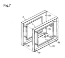
- Fig. 7 is an exploded perspective view showing a conventional double-layered structure of a front cover 2 and a front cabinet 3.
- the front cover 2 has, in the center thereof, a display window 2c for displaying images from the display device body, and is almost identical in shape to the front cabinet 3.
- the front cover 2 has, on the back face thereof, a plurality of hooked lugs 2b for joining the front cover 2 and the front cabinet 3 together, the front cover 2 and the lugs 2b being integrally formed of resin.
- the front cabinet 3 has, on the front face thereof, holes 3b for receiving the lugs 2b of the front cover 2, the holes 3b being integrally formed of resin so as to penetrate through the side walls of the front cabinet 3.
- the front cabinet 3 is put into the front cover 2 with the lugs 2b protruding inward from the side walls of the front cover 2 fit into the corresponding holes 3b formed in the side walls of the front cabinet 3, such that the front cabinet 3 and the front cover 2 are securely fixed together.
- the rear cabinet is fixed to the back of the front cabinet 3 with screws. In this way, the cabinet body is completed.
- a conventional assembly structure of a cabinet Disclosed as a conventional assembly structure of a cabinet are a structure disclosed in JP-A-H11-52883 , in which a front cabinet and a rear cabinet are fixed together with a lug fitting into a tongue flap, a structure disclosed in JP-A-H11-126034 , in which a front cabinet and a rear cabinet are fixed together with screws, and a structure disclosed in JP-A-2000-324425 , in which a front cabinet and a main cabinet are fixed together with an engaging lug engaged in an engaging hole. All of which are directed to a structure proposed for securely fixing the front cabinet and the rear cabinet together. Therefore, no consideration is given to the possibility that the front cabinet and the rear cabinet thus fixed together are disassembled into separate parts.
- an object of the present invention is to provide an assembly structure of a cabinet, the structure that ensures sufficient joint strength between a front cover and a front cabinet while allowing the front cover to be detached from the front cabinet with ease, and that can reduce the number of parts of the cabinet as a whole and thus costs of parts, and to provide a thin display device using such a cabinet.
- a projection protruding outward from the front cabinet is formed on an upper edge of the side wall of the front cabinet, a depression is formed on an upper edge of the side wall of the front cover, a protrusion protruding in a direction in which the side wall of the rear cabinet erects is formed on an upper edge of the side wall thereof.
- the front cabinet is supported between the front cover and the rear cabinet, such that the projection is pressed against the depression by the protrusion and the upper edge of the side wall of the rear cabinet, and the projection is locked by the depression.
- the projection has a wedge shape.
- a thin display device is provided with a cabinet having the assembly structure described above, the cabinet inside which a display device body is placed.
- the projection formed on the upper edge of the side wall of the front cabinet fits into the depression formed on the upper edge of the side wall of the front cover. Since the depression is formed on the upper edge of the side wall, and the projection is not locked by the depression in a direction opposite to a direction in which the front cabinet is attached. This makes it possible to easily detach the front cabinet from the front cover. In addition, it is possible to form the projection and the depression into simple shapes, allowing them to be formed with a die with a high degree of forming efficiency.
- the rear cabinet is urged in a direction toward the front cover.
- the projection formed in the side wall of the front cabinet is pressed against the depression formed in the side wall of the front cover by the upper edge of the side wall of the rear cabinet and the protrusion protruding from the upper edge thereof in a direction in which the side wall erects. This allows the projection to be stably locked by the depression, ensuing constant joint strength between the front cabinet and the front cover.
- front cabinet is fixedly supported between the front cover and the rear cabinet, it is possible to eliminate the need for screws to fix the front cabinet and the front cover together and fix the front cabinet and the rear cabinet together.
- the projection since the projection has a wedge shape, the projection fits into the depression more securely when pressed against it. This allows the projection to be locked by the depression more firmly. As a result, the front cover and the front cabinet are joined together more stably.
- the thin display device is provided with a cabinet having the structure described above, the cabinet inside which a display device body is placed. This makes it possible to provide the thin display device having the above-described advantages.
- a liquid crystal display device is composed of a cabinet built with a front cabinet and a rear cabinet and a liquid crystal display device body placed inside the cabinet.
- the liquid crystal display device body is composed of a liquid crystal display panel, a drive circuit for driving the liquid crystal display panel, a tuner for receiving a broadcast signal, and a circuit substrate on which, for example, a control circuit for controlling different parts is mounted.
- Fig. 1 is an exploded perspective view of a cabinet 1 inside which no liquid crystal display device body is placed.
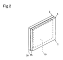
- Fig. 2 is a perspective view showing the back face of the cabinet 1 after assembly.
- the cabinet 1 is composed of a front cabinet 3 and a rear cabinet 4.
- a front cover 2 is attached on the front face of the front cabinet 3, a front cover 2 is attached.
- the front cover 2, the front cabinet 3, and the rear cabinet 4 each have a storage portion surrounded with side walls.
- the front cabinet 3 is put into the front cover 2, such that the outer surfaces of the side walls 3h of the front cabinet 3 are brought into contact with the inner surfaces of the side walls 2h of the front cover 2.
- the front cabinet 3 and the rear cabinet 4 are assembled together, such that the upper edges of the side walls 3h and the side walls 4h make contact with each other.
- the cabinet 1 having a space inside which the liquid crystal display device body 10 is placed is obtained.
- the side walls 3h are covered with the side walls 2h of the front cover 2, and are not shown in Fig. 2 .
- the front cabinet 3 has, in the center thereof, a display window 3c for displaying images from the display device body.
- the display window is also surrounded with the side walls 3h.
- the side walls 3h have a plurality of projections 3a formed on the upper edges thereof, the projections 3a protruding outward from the front cabinet 3. The projections 3a will be described later in detail.
- the front cover 2 is almost identical in shape to the front cabinet 3, and is slightly larger than the front cabinet 3.
- the front cabinet 3 can be put into the front cover 2 by fitting the front cabinet 3 into a space surrounded with the inner and outer side walls 2h of the front cover 2.
- the side walls 2h of the front cover 2 have depressions 2a formed on the upper edges thereof in positions corresponding to the positions where the projections 3a are formed.
- the depressions 2a are so shaped as to receive the projections 3a. As a result, when the front cabinet 3 is put into the front cover 2, the projections 3a make contact with the depressions 2a.
- the front cover 2 has, on the back face thereof, rear cabinet connecting bosses 2f for providing connection with the rear cabinet 4.
- the rear cabinet connecting bosses 2f and front cover connecting bosses 4f are joined together with screws, such that the front cabinet 3 is supported between the front cover 2 and the rear cabinet 4.
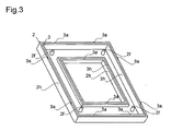
- Fig. 3 is a perspective view showing a state in which the front cabinet 3 is put into the front cover 2.
- the front cabinet 3 fits into the front cover 2, such that the outer surfaces of the side walls 3h of the front cabinet 3 are brought into contact with the inner surfaces of the side walls 2h of the front cover 2, and the projections 3 a of the front cabinet 3 come into contact with the depressions 2a from above, the depressions 2a being formed on the upper edges of the side walls 2h of the front cover 2.
- the projections 3a are not locked by the depressions 2a in the upward direction, making it possible to easily detach the front cabinet 3 from the front cover 2.
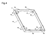
- Fig. 4 is a perspective view showing the front face of the rear cabinet 4.
- the side walls 4h of the rear cabinet 4 have protrusions 4a formed on the upper edges thereof, the protrusions 4a protruding in a direction in which the side walls erect.
- the protrusions 4a are formed so as to be thinner than the side walls 4h of the rear cabinet 4, and are located in positions corresponding to the positions where the projections 3a are formed.
- the rear cabinet 4 has, on the front face thereof, the front cover connecting bosses 4f provided one for each of the rear cabinet connecting bosses 2f formed on the back face of the front cover 2. This makes it possible to fixedly support the front cabinet 3 between the front cover 2 and the rear cabinet 4 by joining the rear cabinet connecting bosses 2f and the front cover connecting bosses 4f together with screws.
- Fig. 5 is a sectional view of the projection 3a, the depression 2a, the protrusion 4a, and the side walls, showing a state in which the front cover 2, the front cabinet 3, and the rear cabinet 4 are yet to be assembled together.
- the projection 3a has a wedge shape, and the depression 2a is so shaped as to receive the wedge-shaped projection 3a.
- the projection 3a makes contact with the depression 2a.
- the projection 3a is caught in the depression 2a due to the shape of the projection 3 a, the projection 3 a is not locked by the depression 2a in the upward direction, making it possible to easily detach the front cabinet 3 from the front cover 2.
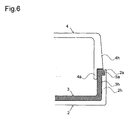
- Fig. 6 is a sectional view of the projection 3a, the depression 2a, the protrusion 4a, and the side walls, showing a state in which the front cover 2, the front cabinet 3, and the rear cabinet 4 are assembled together.
- the upper edge of the side wall 3h of the front cabinet 3 makes contact with the upper edge of the side wall 4h of the rear cabinet 4
- the protrusion 4a formed in the side wall 4h of the rear cabinet 4 makes contact with the inner surface of the side wall 3h.
- the side wall 3h of the front cabinet 3 is supported between the inner bottom surface of the front cover 2 and the side wall 4h of the rear cabinet 4, and the projection 3a is pressed against the depression 2a by the upper edge of the side wall 4h and the protrusion 4a in a portion where the projection 3a and the depression 2a make contact with each other.
- part of the projection 3a securely fits into the depression 2a, whereby the projection 3a is locked by the depression 2a.
- the protrusion 4a making contact with the inner surface of the side wall 3h supports the side wall 3h, and thereby prevents the projection 3a from moving in the lateral direction.
- front cabinet 3 being fixedly supported between the front cover 2 and the rear cabinet 4, it is possible to eliminate the need for the screws used in the conventional example between the front cabinet 3 and the front cover 2 and between the front cabinet 3 and the rear cabinet 4. This helps achieve cost reduction and enhanced working efficiency.
- the edge of the projection 3a may be formed into a shape that allows the projection 3a to fit into the depression 2a more securely at a portion where they make contact with each other, such that the projection 3 a is locked by the depression 2a more firmly.
- a hooked lug and a hole corresponding thereto may be formed in the cabinet of the above-described embodiment.
- the assembly structure of a cabinet according to the invention can be applied not only to liquid crystal display devices but also to plasma display televisions and EL (electroluminescent) televisions.
- the present invention finds wide application in cabinets in general that adopt a double-layered structure.
- the present invention can be applied to cabinets for thin display devices such as liquid crystal displays, plasma displays, and organic EL displays.
Landscapes
- Engineering & Computer Science (AREA)
- Multimedia (AREA)
- Signal Processing (AREA)
- Business, Economics & Management (AREA)
- Finance (AREA)
- Strategic Management (AREA)
- Databases & Information Systems (AREA)
- Human Computer Interaction (AREA)
- Devices For Indicating Variable Information By Combining Individual Elements (AREA)
- Bathtubs, Showers, And Their Attachments (AREA)
Applications Claiming Priority (1)
| Application Number | Priority Date | Filing Date | Title |
|---|---|---|---|
| JP2007143410A JP4379492B2 (ja) | 2007-05-30 | 2007-05-30 | キャビネットの組み立て構造及び薄型表示装置 |
Publications (2)
| Publication Number | Publication Date |
|---|---|
| EP1998564A2 true EP1998564A2 (de) | 2008-12-03 |
| EP1998564A3 EP1998564A3 (de) | 2009-09-02 |
Family
ID=39580081
Family Applications (1)
| Application Number | Title | Priority Date | Filing Date |
|---|---|---|---|
| EP08156316A Withdrawn EP1998564A3 (de) | 2007-05-30 | 2008-05-15 | Gehäuse |
Country Status (3)
| Country | Link |
|---|---|
| US (1) | US8366213B2 (de) |
| EP (1) | EP1998564A3 (de) |
| JP (1) | JP4379492B2 (de) |
Families Citing this family (16)
| Publication number | Priority date | Publication date | Assignee | Title |
|---|---|---|---|---|
| KR101346502B1 (ko) * | 2008-02-21 | 2013-12-31 | 엘지전자 주식회사 | 냉장고 및 냉장고 도어의 제조방법 |
| US8264822B2 (en) | 2009-03-30 | 2012-09-11 | JVC Kenwood Corporation | Image display apparatus and housing assembly configuration |
| JP2010243719A (ja) * | 2009-04-03 | 2010-10-28 | Victor Co Of Japan Ltd | 筐体組み立て構造及び画像表示装置 |
| US20110095660A1 (en) * | 2009-10-28 | 2011-04-28 | Chao-Chun Wang | Bright-Surface Structure and Display with Nut Suspended in Midair |
| KR20110087402A (ko) * | 2010-01-26 | 2011-08-03 | 삼성전자주식회사 | 디스플레이 장치 및 그 전면 커버 제조금형 |
| JP2012080461A (ja) * | 2010-10-05 | 2012-04-19 | Sharp Corp | キャビネット、表示装置及びテレビ受像装置 |
| JP5678760B2 (ja) * | 2011-03-28 | 2015-03-04 | 船井電機株式会社 | 表示装置および表示モジュール |
| JP5447448B2 (ja) | 2011-08-01 | 2014-03-19 | 船井電機株式会社 | 表示装置キャビネット |
| US20150289398A1 (en) * | 2012-10-30 | 2015-10-08 | Sharp Kabushiki Kaisha | Display device |
| US20140252779A1 (en) * | 2013-03-11 | 2014-09-11 | Nokia Corporation | Locking Arrangement |
| JP6191338B2 (ja) * | 2013-09-04 | 2017-09-06 | ソニー株式会社 | 筐体および筐体部品 |
| CN103969878A (zh) * | 2014-05-21 | 2014-08-06 | 深圳市华星光电技术有限公司 | 液晶显示装置 |
| JP6717677B2 (ja) * | 2016-06-14 | 2020-07-01 | クラリオン株式会社 | 表示装置 |
| WO2019128369A1 (zh) * | 2017-12-27 | 2019-07-04 | 佛山市顺德区美的电热电器制造有限公司 | 用于电饭煲的显示组件和具有该显示组件的电饭煲 |
| CN108665802B (zh) * | 2018-06-29 | 2023-12-26 | 深圳利亚德光电有限公司 | 锁紧机构及具有其的显示屏 |
| KR102344046B1 (ko) * | 2020-03-31 | 2021-12-28 | 엘지전자 주식회사 | 디스플레이 장치 |
Citations (7)
| Publication number | Priority date | Publication date | Assignee | Title |
|---|---|---|---|---|
| JPH11126034A (ja) | 1997-10-23 | 1999-05-11 | Citizen Watch Co Ltd | 液晶表示装置及び液晶テレビジョン受像機 |
| JP2000324425A (ja) | 1999-05-14 | 2000-11-24 | Sony Corp | 電子機器用キャビネット |
| WO2003005402A1 (en) | 2001-06-30 | 2003-01-16 | Samsung Corning Co., Ltd. | Flat panel for cathode-ray tube |
| US20050024552A1 (en) | 2003-07-28 | 2005-02-03 | Benq Corporation | Liquid crystal display and manufacturing method thereof |
| US20050286214A1 (en) | 2004-06-25 | 2005-12-29 | Asustek Computer Inc. | Electronic device with protection function |
| US20060077629A1 (en) | 2004-10-08 | 2006-04-13 | Mikio Shiraishi | Display apparatus |
| EP1777054A1 (de) | 2005-10-24 | 2007-04-25 | Funai Electric Co., Ltd. | Spritzgussform, Spritzgiessverfahren für Flachbildschirmgehäuse und Plasmafernseher |
Family Cites Families (32)
| Publication number | Priority date | Publication date | Assignee | Title |
|---|---|---|---|---|
| US4017129A (en) * | 1975-11-14 | 1977-04-12 | Zenith Radio Corporation | Television receiver cabinet with formed decorative front |
| JPH04132376A (ja) * | 1990-09-21 | 1992-05-06 | Matsushita Electric Ind Co Ltd | テレビ受像器の筐体 |
| US5419626A (en) * | 1993-09-01 | 1995-05-30 | Ncr Corporation | Computer housing seal |
| JP3097799B2 (ja) * | 1993-12-27 | 2000-10-10 | 三菱電機株式会社 | 表示装置ならびにその固定構造および組立て方法 |
| US5568357A (en) * | 1994-06-15 | 1996-10-22 | Metanetics Corporation | Display support having cradled damping caps for floating core shock absorption |
| US5613237A (en) * | 1994-10-17 | 1997-03-18 | Motorola, Inc. | Housing latch system utilizing an elastomeric interlocking band |
| US5570267A (en) * | 1995-07-12 | 1996-10-29 | Ma; Hsi-Kuang | Flat display module |
| JPH09297542A (ja) * | 1996-05-09 | 1997-11-18 | Toshiba Corp | 表示装置およびこの表示装置を有する携帯形機器 |
| JP3367343B2 (ja) * | 1996-07-22 | 2003-01-14 | 松下電器産業株式会社 | 投射型テレビジョン受像機のキャビネット装置と成型用金型および樹脂成型方法 |
| JPH1152883A (ja) | 1997-07-31 | 1999-02-26 | Nec Home Electron Ltd | デイスプレイ装置用キャビネットの組立構造 |
| US6310767B1 (en) * | 1999-02-26 | 2001-10-30 | Case Corporation | Shield for a display unit |
| KR200285944Y1 (ko) * | 1999-05-26 | 2002-08-22 | 삼성전자 주식회사 | 엘씨디 모니터의 샤시 고정장치 |
| JP2001036262A (ja) * | 1999-07-26 | 2001-02-09 | Optex Co Ltd | 無線式防水型押しボタンスイッチ |
| US6493045B1 (en) * | 1999-12-30 | 2002-12-10 | Apple Computer, Inc. | Enclosure assembly |
| JP3631663B2 (ja) * | 2000-05-26 | 2005-03-23 | Necパーソナルプロダクツ株式会社 | Lcdパネルの固定構造 |
| US6575541B1 (en) * | 2000-10-11 | 2003-06-10 | Igt | Translucent monitor masks, substrate and apparatus for removable attachment to gaming device cabinet |
| KR100381787B1 (ko) * | 2000-12-27 | 2003-04-26 | 삼성전자주식회사 | 디스플레이장치 |
| TW508061U (en) * | 2001-08-03 | 2002-10-21 | Hannstar Display Corp | Structure of heat radiation for joining of parts |
| KR100793729B1 (ko) * | 2001-09-27 | 2008-01-10 | 삼성전자주식회사 | 액정표시장치 |
| JP2003167235A (ja) * | 2001-12-03 | 2003-06-13 | Nec Kagoshima Ltd | 液晶表示装置の組み立て構造及びその組み立て方法 |
| KR100424763B1 (ko) * | 2001-12-19 | 2004-03-30 | 삼성전자주식회사 | 프로젝션 텔레비젼의 스크린 고정장치 |
| US6919678B2 (en) * | 2002-09-03 | 2005-07-19 | Bloomberg Lp | Bezel-less electric display |
| KR100490156B1 (ko) * | 2002-10-25 | 2005-05-16 | 엘지전자 주식회사 | Lcd 모니터의 모듈고정장치 |
| JP4224706B2 (ja) * | 2004-04-16 | 2009-02-18 | 船井電機株式会社 | プラズマテレビジョン、パネル表示型テレビジョンおよびパネル表示型テレビジョン組立方法 |
| US7529082B2 (en) * | 2004-04-16 | 2009-05-05 | Funai Electric Co., Ltd. | Plasma television, flat panel display fixing structure, flat panel television, and method of assembling flat panel television |
| KR100869102B1 (ko) * | 2004-10-19 | 2008-11-17 | 삼성에스디아이 주식회사 | 플라즈마 표시장치 조립체와, 이의 제조방법 |
| JP3112212U (ja) * | 2005-04-26 | 2005-08-04 | 船井電機株式会社 | パネル表示型テレビジョンおよびキャビネット構造 |
| JP4481218B2 (ja) * | 2005-06-29 | 2010-06-16 | 株式会社 日立ディスプレイズ | 液晶表示装置 |
| KR100731364B1 (ko) * | 2005-11-02 | 2007-06-21 | 엘지전자 주식회사 | 영상 디스플레이 기기 |
| JP4572828B2 (ja) * | 2005-12-08 | 2010-11-04 | ソニー株式会社 | 画像表示装置 |
| JP4893302B2 (ja) * | 2006-12-28 | 2012-03-07 | 船井電機株式会社 | パネル型テレビジョンおよび表示パネル取付構造 |
| TWI389067B (zh) * | 2010-06-29 | 2013-03-11 | Compal Electronics Inc | 顯示模組及其組裝方法 |
-
2007
- 2007-05-30 JP JP2007143410A patent/JP4379492B2/ja not_active Expired - Fee Related
-
2008
- 2008-05-15 EP EP08156316A patent/EP1998564A3/de not_active Withdrawn
- 2008-05-29 US US12/155,080 patent/US8366213B2/en not_active Expired - Fee Related
Patent Citations (7)
| Publication number | Priority date | Publication date | Assignee | Title |
|---|---|---|---|---|
| JPH11126034A (ja) | 1997-10-23 | 1999-05-11 | Citizen Watch Co Ltd | 液晶表示装置及び液晶テレビジョン受像機 |
| JP2000324425A (ja) | 1999-05-14 | 2000-11-24 | Sony Corp | 電子機器用キャビネット |
| WO2003005402A1 (en) | 2001-06-30 | 2003-01-16 | Samsung Corning Co., Ltd. | Flat panel for cathode-ray tube |
| US20050024552A1 (en) | 2003-07-28 | 2005-02-03 | Benq Corporation | Liquid crystal display and manufacturing method thereof |
| US20050286214A1 (en) | 2004-06-25 | 2005-12-29 | Asustek Computer Inc. | Electronic device with protection function |
| US20060077629A1 (en) | 2004-10-08 | 2006-04-13 | Mikio Shiraishi | Display apparatus |
| EP1777054A1 (de) | 2005-10-24 | 2007-04-25 | Funai Electric Co., Ltd. | Spritzgussform, Spritzgiessverfahren für Flachbildschirmgehäuse und Plasmafernseher |
Also Published As
| Publication number | Publication date |
|---|---|
| US8366213B2 (en) | 2013-02-05 |
| JP2008298964A (ja) | 2008-12-11 |
| US20080297013A1 (en) | 2008-12-04 |
| EP1998564A3 (de) | 2009-09-02 |
| JP4379492B2 (ja) | 2009-12-09 |
Similar Documents
| Publication | Publication Date | Title |
|---|---|---|
| EP1998564A2 (de) | Gehäuse | |
| JP4150030B2 (ja) | ディスプレイモジュール用シャーシーベースのエッジ補強材及びそれを具備したディスプレイモジュール | |
| JP2002215061A (ja) | ディスプレイ装置 | |
| US8665391B2 (en) | Liquid crystal display device and its case | |
| JP2003202940A (ja) | 携帯用コンピュータ | |
| JP2010068388A (ja) | 電子機器のキャビネット | |
| US6536855B2 (en) | Front cabinet and television set | |
| JP2010068389A (ja) | 支持スタンド | |
| CN101761834B (zh) | 背光模组及显示装置 | |
| EP3879514B1 (de) | Rahmenkörper und elektronischer bilderrahmen | |
| US11800052B2 (en) | Display module and television | |
| KR100400754B1 (ko) | 평판형 표시장치의 결합구조 | |
| CN210429115U (zh) | 显示器的框架装置 | |
| JP2012058546A (ja) | 表示装置及びテレビ受信装置 | |
| US20120127377A1 (en) | Television and Electronic Device | |
| US8659883B2 (en) | Liquid crystal display device with connector | |
| US20070206123A1 (en) | Liquid crystal television | |
| JP5198640B2 (ja) | テレビジョン受像機および電子機器 | |
| EP2166428A1 (de) | Gestellbefestigungsstruktur | |
| CN212437803U (zh) | 储物柜 | |
| CN210896393U (zh) | 显示装置及具有其的空调器 | |
| CN113951639A (zh) | 储物柜 | |
| KR100551029B1 (ko) | 플라즈마 디스플레이 장치용 섀시 베이스 및 이를 이용한플라즈마 디스플레이 장치 | |
| JP3107250U (ja) | ディスプレイ装置 | |
| KR100617191B1 (ko) | 은폐형 슬라이드 결합 구조를 갖는 캐비넷 및 백커버일체형 모니터 케이스 |
Legal Events
| Date | Code | Title | Description |
|---|---|---|---|
| PUAI | Public reference made under article 153(3) epc to a published international application that has entered the european phase |
Free format text: ORIGINAL CODE: 0009012 |
|
| AK | Designated contracting states |
Kind code of ref document: A2 Designated state(s): AT BE BG CH CY CZ DE DK EE ES FI FR GB GR HR HU IE IS IT LI LT LU LV MC MT NL NO PL PT RO SE SI SK TR |
|
| AX | Request for extension of the european patent |
Extension state: AL BA MK RS |
|
| PUAL | Search report despatched |
Free format text: ORIGINAL CODE: 0009013 |
|
| AK | Designated contracting states |
Kind code of ref document: A3 Designated state(s): AT BE BG CH CY CZ DE DK EE ES FI FR GB GR HR HU IE IS IT LI LT LU LV MC MT NL NO PL PT RO SE SI SK TR |
|
| AX | Request for extension of the european patent |
Extension state: AL BA MK RS |
|
| 17P | Request for examination filed |
Effective date: 20091216 |
|
| AKX | Designation fees paid |
Designated state(s): DE FR GB PL |
|
| 17Q | First examination report despatched |
Effective date: 20160701 |
|
| STAA | Information on the status of an ep patent application or granted ep patent |
Free format text: STATUS: EXAMINATION IS IN PROGRESS |
|
| STAA | Information on the status of an ep patent application or granted ep patent |
Free format text: STATUS: THE APPLICATION IS DEEMED TO BE WITHDRAWN |
|
| 18D | Application deemed to be withdrawn |
Effective date: 20161112 |