EP1998359A2 - Schlitzventil - Google Patents
Schlitzventil Download PDFInfo
- Publication number
- EP1998359A2 EP1998359A2 EP07016951A EP07016951A EP1998359A2 EP 1998359 A2 EP1998359 A2 EP 1998359A2 EP 07016951 A EP07016951 A EP 07016951A EP 07016951 A EP07016951 A EP 07016951A EP 1998359 A2 EP1998359 A2 EP 1998359A2
- Authority
- EP
- European Patent Office
- Prior art keywords
- housing
- door
- manifold
- sealing member
- valve assembly
- Prior art date
- Legal status (The legal status is an assumption and is not a legal conclusion. Google has not performed a legal analysis and makes no representation as to the accuracy of the status listed.)
- Withdrawn
Links
Images




Classifications
-
- H—ELECTRICITY
- H10—SEMICONDUCTOR DEVICES; ELECTRIC SOLID-STATE DEVICES NOT OTHERWISE PROVIDED FOR
- H10D—INORGANIC ELECTRIC SEMICONDUCTOR DEVICES
- H10D48/00—Individual devices not covered by groups H10D1/00 - H10D44/00
- H10D48/01—Manufacture or treatment
- H10D48/04—Manufacture or treatment of devices having bodies comprising selenium or tellurium in uncombined form
- H10D48/042—Preparation of foundation plates
-
- H—ELECTRICITY
- H10—SEMICONDUCTOR DEVICES; ELECTRIC SOLID-STATE DEVICES NOT OTHERWISE PROVIDED FOR
- H10P—GENERIC PROCESSES OR APPARATUS FOR THE MANUFACTURE OR TREATMENT OF DEVICES COVERED BY CLASS H10
- H10P72/00—Handling or holding of wafers, substrates or devices during manufacture or treatment thereof
- H10P72/04—Apparatus for manufacture or treatment
- H10P72/0441—Apparatus for sealing, encapsulating, glassing, decapsulating or the like
-
- H—ELECTRICITY
- H10—SEMICONDUCTOR DEVICES; ELECTRIC SOLID-STATE DEVICES NOT OTHERWISE PROVIDED FOR
- H10P—GENERIC PROCESSES OR APPARATUS FOR THE MANUFACTURE OR TREATMENT OF DEVICES COVERED BY CLASS H10
- H10P95/00—Generic processes or apparatus for manufacture or treatments not covered by the other groups of this subclass
Definitions
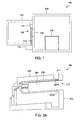
- Figure 2A illustrates a perspective view of a valve assembly in accordance with some embodiments of the invention.
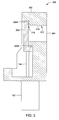
- the manifold 211 may be formed in any suitable manner, such as by machining a plurality of holes through the housing 202 and selectively sealing portions of the holes to define the desired path of the manifold 211.
- a plurality of holes 550, 560, 570, 580 may be machined into the housing 202.
- the holes 550, 560, 570, 580 intersect to form a fluid passage through the housing 202.
- Selective portions of the holes 550, 560, 570, 580 may be sealed (as shown in phantom by 562, 572, 582) to define the manifold 211.
- an inert gas may be provided from a gas source (not shown) to the manifold 211.
- the inert gas will exit the manifold 211 via the plurality of gas holes 210 to form a gas curtain proximate the compressible sealing member 208.
- the pressurized gas may be any process compatible inert gas such as nitrogen, noble gases, or other gas that is inert to the materials of the seal and not detrimental to the process occurring within the process chamber.
- the gas curtain may be formed prior to the supply of a process gas or prior to commencing processing within the process chamber to avoid initial exposure of the compressible sealing member to any corrosive atmosphere within the chamber.
- the pressurized gas may be supplied at a predefined flow rate to form the gas curtain as desired and restrict the exposure of the compressible sealing member to any corrosive atmosphere within the chamber.
- the gas curtain may continue to be provided for a predefined time after the completion of process, after purging the process chamber, and/or after opening the door 206, to further restrict the exposure of the compressible sealing member to any corrosive atmosphere within the chamber.
- the predefined time may be calculated based on the time required for the concentration of the process gases to reach to a predefined limit that practically does not degrade the compressible sealing member 208.
- the physical barrier 212 may be at least one of a protrusion (or corresponding recess), ledge, lip, flange, boss, wall, surface, or other member or element that provides an obstruction between the compressible sealing member and the opening 204 (or interior of the process chamber) when the door 206 is in a closed position.
- one or more manifolds may be formed in the housing, and/or optionally, the door of the valve assembly.
- a plurality of gas holes may be formed to fluidly couple the manifolds to a desired region of the valve assembly to facilitate creating and maintaining a gas curtain as described above.
- the manifolds may comprise an inlet and at least a portion disposed in a region that facilitates fluid coupling to the gas holes.
- the manifolds may be formed by drilling a plurality of holes
Landscapes
- Valve Housings (AREA)
- Sliding Valves (AREA)
- Details Of Valves (AREA)
- Chemical Vapour Deposition (AREA)
Applications Claiming Priority (1)
| Application Number | Priority Date | Filing Date | Title |
|---|---|---|---|
| US11/756,632 US7806383B2 (en) | 2007-06-01 | 2007-06-01 | Slit valve |
Publications (1)
| Publication Number | Publication Date |
|---|---|
| EP1998359A2 true EP1998359A2 (de) | 2008-12-03 |
Family
ID=38566796
Family Applications (1)
| Application Number | Title | Priority Date | Filing Date |
|---|---|---|---|
| EP07016951A Withdrawn EP1998359A2 (de) | 2007-06-01 | 2007-08-29 | Schlitzventil |
Country Status (6)
| Country | Link |
|---|---|
| US (1) | US7806383B2 (de) |
| EP (1) | EP1998359A2 (de) |
| JP (1) | JP2008298280A (de) |
| KR (1) | KR100934517B1 (de) |
| CN (1) | CN101314867B (de) |
| TW (1) | TWI363152B (de) |
Families Citing this family (13)
| Publication number | Priority date | Publication date | Assignee | Title |
|---|---|---|---|---|
| US8011381B2 (en) * | 2008-10-02 | 2011-09-06 | Applied Material, Inc. | Balanced purge slit valve |
| JP5748847B2 (ja) * | 2010-06-21 | 2015-07-15 | ロス エウロパ ゲゼルシャフト ミット ベシュレンクテル ハフツングROSS EUROPA GmbH | ガラス製造機に使用する弁ブロック用互換可能弁 |
| JP5725782B2 (ja) * | 2010-09-30 | 2015-05-27 | 株式会社ブイテックス | バルブ装置 |
| EP2551565A1 (de) | 2011-07-28 | 2013-01-30 | VAT Holding AG | Vakuumventil und Verschlussglied zum gasdichten Schliessen eines Fliesswegs mittels einer Linearbewegung |
| CN103320852A (zh) * | 2013-06-14 | 2013-09-25 | 光垒光电科技(上海)有限公司 | 用于外延沉积的反应腔 |
| US9587749B2 (en) * | 2013-08-12 | 2017-03-07 | Applied Materials Israel, Ltd. | Slit valve with a pressurized gas bearing |
| DE102015104556A1 (de) * | 2015-03-26 | 2016-09-29 | Z & J Technologies Gmbh | Dreifachdichtsitz mit Gasspülung für einen Leitrohrschieber |
| US10504700B2 (en) | 2015-08-27 | 2019-12-10 | Applied Materials, Inc. | Plasma etching systems and methods with secondary plasma injection |
| WO2019027863A1 (en) * | 2017-07-31 | 2019-02-07 | Applied Materials, Inc. | GAS SUPPLY ELEMENT WITH DEFLECTOR |
| CN112530830A (zh) * | 2019-09-18 | 2021-03-19 | 中微半导体设备(上海)股份有限公司 | 基片处理系统、阀板组件及其基片处理系统的工作方法 |
| CN112530829A (zh) * | 2019-09-18 | 2021-03-19 | 中微半导体设备(上海)股份有限公司 | 基片处理系统、阀板组件及其基片处理系统的工作方法 |
| EP3937219B1 (de) * | 2020-07-06 | 2023-08-30 | Siltronic AG | Verfahren zum erzeugen eines gasvorhangs aus spülgas in einem schlitzventiltunnel und schlitzventiltunnel |
| CN114352171A (zh) * | 2021-12-30 | 2022-04-15 | 苏州子山半导体科技有限公司 | 一种新型的真空密封门板结构 |
Family Cites Families (14)
| Publication number | Priority date | Publication date | Assignee | Title |
|---|---|---|---|---|
| US1135280A (en) * | 1914-09-10 | 1915-04-13 | David Hamilton | Gate-valve. |
| DE3717724A1 (de) * | 1987-05-26 | 1988-12-08 | Schertler Siegfried | Ventilschieber mit einem schiebergehaeuse |
| DE3831249A1 (de) * | 1988-09-14 | 1990-03-22 | Schertler Siegfried | Ventilschieber |
| DE3901695A1 (de) * | 1989-01-21 | 1990-07-26 | Klein Schanzlin & Becker Ag | Hubventil |
| US5271602A (en) * | 1992-04-13 | 1993-12-21 | The Japan Steel Works Ltd. | Vacuum gate valve |
| DE19601541A1 (de) * | 1995-01-27 | 1996-08-01 | Seiko Seiki Kk | In einer Vakuumumgebung einsetzbares Vertikaltransfersystem sowie dazugehöriges Absperrventilsystem |
| US5579718A (en) * | 1995-03-31 | 1996-12-03 | Applied Materials, Inc. | Slit valve door |
| US6056267A (en) * | 1998-05-19 | 2000-05-02 | Applied Materials, Inc. | Isolation valve with extended seal life |
| US6079693A (en) * | 1998-05-20 | 2000-06-27 | Applied Komatsu Technology, Inc. | Isolation valves |
| US6347918B1 (en) * | 1999-01-27 | 2002-02-19 | Applied Materials, Inc. | Inflatable slit/gate valve |
| US6764265B2 (en) * | 2002-01-07 | 2004-07-20 | Applied Materials Inc. | Erosion resistant slit valve |
| JP2004103683A (ja) | 2002-09-06 | 2004-04-02 | Mitsubishi Heavy Ind Ltd | プラズマ処理装置と搬送装置との間の隔壁構造 |
| KR20050062751A (ko) | 2003-12-22 | 2005-06-27 | 어댑티브프라즈마테크놀로지 주식회사 | 이중 도어 게이트 밸브를 가지는 챔버 장비 |
| KR20060036689A (ko) * | 2004-10-26 | 2006-05-02 | 삼성전자주식회사 | 반도체 공정 장비의 게이트 밸브 |
-
2007
- 2007-06-01 US US11/756,632 patent/US7806383B2/en not_active Expired - Fee Related
- 2007-08-08 CN CN2007101380578A patent/CN101314867B/zh active Active
- 2007-08-20 TW TW096130755A patent/TWI363152B/zh not_active IP Right Cessation
- 2007-08-29 EP EP07016951A patent/EP1998359A2/de not_active Withdrawn
- 2007-08-31 KR KR1020070088295A patent/KR100934517B1/ko not_active Expired - Fee Related
- 2007-08-31 JP JP2007226706A patent/JP2008298280A/ja not_active Withdrawn
Also Published As
| Publication number | Publication date |
|---|---|
| KR20080105951A (ko) | 2008-12-04 |
| CN101314867B (zh) | 2012-07-18 |
| US20080296304A1 (en) | 2008-12-04 |
| TW200848642A (en) | 2008-12-16 |
| KR100934517B1 (ko) | 2009-12-29 |
| TWI363152B (en) | 2012-05-01 |
| US7806383B2 (en) | 2010-10-05 |
| CN101314867A (zh) | 2008-12-03 |
| JP2008298280A (ja) | 2008-12-11 |
Similar Documents
| Publication | Publication Date | Title |
|---|---|---|
| US7806383B2 (en) | Slit valve | |
| KR102802649B1 (ko) | 기판 처리 장치 | |
| KR102802641B1 (ko) | 기판 처리 장치 | |
| JP6822953B2 (ja) | 基板キャリア及びパージチャンバの環境制御を伴う基板処理のシステム、装置、及び方法 | |
| KR102269564B1 (ko) | 팩토리 인터페이스 챔버 필터 퍼지를 이용한 기판 프로세싱 장치 및 방법들 | |
| US6602346B1 (en) | Gas-purged vacuum valve | |
| US20130239889A1 (en) | Valve purge assembly for semiconductor manufacturing tools | |
| JP4916140B2 (ja) | 真空処理システム | |
| US20020134506A1 (en) | Transfer chamber with side wall port | |
| US20210395881A1 (en) | High temperature face plate for deposition application | |
| US10119191B2 (en) | High flow gas diffuser assemblies, systems, and methods | |
| JP7712912B2 (ja) | 分離バルブ | |
| JP2020536373A (ja) | デュアルポート遠隔プラズマクリーン分離バルブ | |
| JP7441908B2 (ja) | 基板処理装置 | |
| KR20220054679A (ko) | 반도체 장비를 위한 수착 (sorption) 챔버 벽들 | |
| KR102471048B1 (ko) | 저입자 보호 플래퍼 밸브 | |
| KR20250117414A (ko) | 성막 장치 및 성막 방법 | |
| KR100684879B1 (ko) | 기판 처리 장치 | |
| US20060191636A1 (en) | Valve assembly, semiconductor device manufacturing apparatus comprising the same, and method of cleaning a trap of a semiconductor device manufactuing apparatus | |
| KR20030056749A (ko) | 반도체 공정챔버의 슬릿밸브 | |
| KR20070081833A (ko) | 기판 처리 설비 | |
| KR20040095055A (ko) | 반도체 기판 가공 장치의 진공 시스템 | |
| KR20070038328A (ko) | 반도체 소자 제조용 장비 | |
| KR20060078747A (ko) | 로드락 챔버 및 그 사용 방법 | |
| KR20060103559A (ko) | 진공 시스템 |
Legal Events
| Date | Code | Title | Description |
|---|---|---|---|
| PUAI | Public reference made under article 153(3) epc to a published international application that has entered the european phase |
Free format text: ORIGINAL CODE: 0009012 |
|
| AK | Designated contracting states |
Kind code of ref document: A2 Designated state(s): AT BE BG CH CY CZ DE DK EE ES FI FR GB GR HU IE IS IT LI LT LU LV MC MT NL PL PT RO SE SI SK TR |
|
| AX | Request for extension of the european patent |
Extension state: AL BA HR MK RS |
|
| STAA | Information on the status of an ep patent application or granted ep patent |
Free format text: STATUS: THE APPLICATION IS DEEMED TO BE WITHDRAWN |
|
| 18D | Application deemed to be withdrawn |
Effective date: 20110301 |