EP1998059B1 - Wälzlager, haltersegment und hauptwellenstützstruktur für windgetriebenen generator - Google Patents
Wälzlager, haltersegment und hauptwellenstützstruktur für windgetriebenen generator Download PDFInfo
- Publication number
- EP1998059B1 EP1998059B1 EP06823170.3A EP06823170A EP1998059B1 EP 1998059 B1 EP1998059 B1 EP 1998059B1 EP 06823170 A EP06823170 A EP 06823170A EP 1998059 B1 EP1998059 B1 EP 1998059B1
- Authority
- EP
- European Patent Office
- Prior art keywords
- retainer
- diameter side
- retainer segment
- rolling bearing
- Prior art date
- Legal status (The legal status is an assumption and is not a legal conclusion. Google has not performed a legal analysis and makes no representation as to the accuracy of the status listed.)
- Active
Links
- 238000005096 rolling process Methods 0.000 title claims description 78
- 239000011347 resin Substances 0.000 claims description 8
- 229920005989 resin Polymers 0.000 claims description 8
- 238000005461 lubrication Methods 0.000 description 8
- 238000001746 injection moulding Methods 0.000 description 3
- 238000004519 manufacturing process Methods 0.000 description 3
- 239000000470 constituent Substances 0.000 description 1
- 238000005520 cutting process Methods 0.000 description 1
- 239000000463 material Substances 0.000 description 1
- 230000000717 retained effect Effects 0.000 description 1
Images

Classifications
-
- F—MECHANICAL ENGINEERING; LIGHTING; HEATING; WEAPONS; BLASTING
- F16—ENGINEERING ELEMENTS AND UNITS; GENERAL MEASURES FOR PRODUCING AND MAINTAINING EFFECTIVE FUNCTIONING OF MACHINES OR INSTALLATIONS; THERMAL INSULATION IN GENERAL
- F16C—SHAFTS; FLEXIBLE SHAFTS; ELEMENTS OR CRANKSHAFT MECHANISMS; ROTARY BODIES OTHER THAN GEARING ELEMENTS; BEARINGS
- F16C33/00—Parts of bearings; Special methods for making bearings or parts thereof
- F16C33/30—Parts of ball or roller bearings
- F16C33/46—Cages for rollers or needles
- F16C33/51—Cages for rollers or needles formed of unconnected members
- F16C33/513—Cages for rollers or needles formed of unconnected members formed of arcuate segments for carrying one or more rollers
-
- F—MECHANICAL ENGINEERING; LIGHTING; HEATING; WEAPONS; BLASTING
- F03—MACHINES OR ENGINES FOR LIQUIDS; WIND, SPRING, OR WEIGHT MOTORS; PRODUCING MECHANICAL POWER OR A REACTIVE PROPULSIVE THRUST, NOT OTHERWISE PROVIDED FOR
- F03D—WIND MOTORS
- F03D80/00—Details, components or accessories not provided for in groups F03D1/00 - F03D17/00
- F03D80/70—Bearing or lubricating arrangements
-
- F—MECHANICAL ENGINEERING; LIGHTING; HEATING; WEAPONS; BLASTING
- F16—ENGINEERING ELEMENTS AND UNITS; GENERAL MEASURES FOR PRODUCING AND MAINTAINING EFFECTIVE FUNCTIONING OF MACHINES OR INSTALLATIONS; THERMAL INSULATION IN GENERAL
- F16C—SHAFTS; FLEXIBLE SHAFTS; ELEMENTS OR CRANKSHAFT MECHANISMS; ROTARY BODIES OTHER THAN GEARING ELEMENTS; BEARINGS
- F16C33/00—Parts of bearings; Special methods for making bearings or parts thereof
- F16C33/30—Parts of ball or roller bearings
- F16C33/46—Cages for rollers or needles
- F16C33/4605—Details of interaction of cage and race, e.g. retention or centring
-
- F—MECHANICAL ENGINEERING; LIGHTING; HEATING; WEAPONS; BLASTING
- F16—ENGINEERING ELEMENTS AND UNITS; GENERAL MEASURES FOR PRODUCING AND MAINTAINING EFFECTIVE FUNCTIONING OF MACHINES OR INSTALLATIONS; THERMAL INSULATION IN GENERAL
- F16C—SHAFTS; FLEXIBLE SHAFTS; ELEMENTS OR CRANKSHAFT MECHANISMS; ROTARY BODIES OTHER THAN GEARING ELEMENTS; BEARINGS
- F16C33/00—Parts of bearings; Special methods for making bearings or parts thereof
- F16C33/30—Parts of ball or roller bearings
- F16C33/46—Cages for rollers or needles
- F16C33/467—Details of individual pockets, e.g. shape or roller retaining means
-
- F—MECHANICAL ENGINEERING; LIGHTING; HEATING; WEAPONS; BLASTING
- F16—ENGINEERING ELEMENTS AND UNITS; GENERAL MEASURES FOR PRODUCING AND MAINTAINING EFFECTIVE FUNCTIONING OF MACHINES OR INSTALLATIONS; THERMAL INSULATION IN GENERAL
- F16C—SHAFTS; FLEXIBLE SHAFTS; ELEMENTS OR CRANKSHAFT MECHANISMS; ROTARY BODIES OTHER THAN GEARING ELEMENTS; BEARINGS
- F16C19/00—Bearings with rolling contact, for exclusively rotary movement
- F16C19/22—Bearings with rolling contact, for exclusively rotary movement with bearing rollers essentially of the same size in one or more circular rows, e.g. needle bearings
- F16C19/34—Bearings with rolling contact, for exclusively rotary movement with bearing rollers essentially of the same size in one or more circular rows, e.g. needle bearings for both radial and axial load
- F16C19/36—Bearings with rolling contact, for exclusively rotary movement with bearing rollers essentially of the same size in one or more circular rows, e.g. needle bearings for both radial and axial load with a single row of rollers
- F16C19/364—Bearings with rolling contact, for exclusively rotary movement with bearing rollers essentially of the same size in one or more circular rows, e.g. needle bearings for both radial and axial load with a single row of rollers with tapered rollers, i.e. rollers having essentially the shape of a truncated cone
-
- F—MECHANICAL ENGINEERING; LIGHTING; HEATING; WEAPONS; BLASTING
- F16—ENGINEERING ELEMENTS AND UNITS; GENERAL MEASURES FOR PRODUCING AND MAINTAINING EFFECTIVE FUNCTIONING OF MACHINES OR INSTALLATIONS; THERMAL INSULATION IN GENERAL
- F16C—SHAFTS; FLEXIBLE SHAFTS; ELEMENTS OR CRANKSHAFT MECHANISMS; ROTARY BODIES OTHER THAN GEARING ELEMENTS; BEARINGS
- F16C2300/00—Application independent of particular apparatuses
- F16C2300/10—Application independent of particular apparatuses related to size
- F16C2300/14—Large applications, e.g. bearings having an inner diameter exceeding 500 mm
-
- F—MECHANICAL ENGINEERING; LIGHTING; HEATING; WEAPONS; BLASTING
- F16—ENGINEERING ELEMENTS AND UNITS; GENERAL MEASURES FOR PRODUCING AND MAINTAINING EFFECTIVE FUNCTIONING OF MACHINES OR INSTALLATIONS; THERMAL INSULATION IN GENERAL
- F16C—SHAFTS; FLEXIBLE SHAFTS; ELEMENTS OR CRANKSHAFT MECHANISMS; ROTARY BODIES OTHER THAN GEARING ELEMENTS; BEARINGS
- F16C2360/00—Engines or pumps
- F16C2360/31—Wind motors
-
- Y—GENERAL TAGGING OF NEW TECHNOLOGICAL DEVELOPMENTS; GENERAL TAGGING OF CROSS-SECTIONAL TECHNOLOGIES SPANNING OVER SEVERAL SECTIONS OF THE IPC; TECHNICAL SUBJECTS COVERED BY FORMER USPC CROSS-REFERENCE ART COLLECTIONS [XRACs] AND DIGESTS
- Y02—TECHNOLOGIES OR APPLICATIONS FOR MITIGATION OR ADAPTATION AGAINST CLIMATE CHANGE
- Y02E—REDUCTION OF GREENHOUSE GAS [GHG] EMISSIONS, RELATED TO ENERGY GENERATION, TRANSMISSION OR DISTRIBUTION
- Y02E10/00—Energy generation through renewable energy sources
- Y02E10/70—Wind energy
- Y02E10/72—Wind turbines with rotation axis in wind direction
Definitions
- the present invention relates to a rolling bearing, a retainer segment, and a main shaft support structure of a wind-power generator.
- a rolling bearing comprises an outer ring, an inner ring, a plurality of rollers arranged between the outer ring and the inner ring, and a retainer for holding the plurality of rollers in general.
- the retainer for holding the rollers includes various kinds such as a resin retainer, a pressed retainer, a ground retainer, and a welded retainer depending on its material and manufacturing method, and those are used based on purposes and characteristics.
- the retainer is an integrated type, that is, it comprises one annular part in general.
- FIG. 10 is a perspective view showing a retainer segment of the split type retainer disclosed in the European Patent Publication No. 1408248A2 .
- a retainer segment 101a has a plurality of pillar parts 103 extending in an axial direction so as to form a plurality of pockets 104 for holding rollers, and connection parts 102a and 102b extending in a circumferential direction so as to connect the plurality of pillar parts 103.
- an inner diameter-side roller stopper part is provided to prevent the roller housed in the pocket 104 from coming out toward the inner diameter side.
- an outer-diameter side roller stopper part to prevent the roller from coming out toward the outer diameter side is not provided on the outer diameter side, and a flat part is provided.
- a projection 106a to keep a distance from an outer ring is provided at an end face of the pillar part 103 on the outer diameter side and a projection 106b (not shown) to keep a distance from an inner ring is provided at an end face of the pillar part 103 on the inner diameter side.
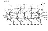
- Fig. 11 is a sectional view showing a part of a rolling bearing containing the retainer segment 101a shown in Fig. 10 .
- the constitution of a rolling bearing 111 containing the retainer segment 101a will be described with reference to Figs. 10 and 11 .
- the rolling bearing 111 has an outer ring 112, an inner ring 113, a plurality of rollers 114, and the plurality of retainer segments 101a, 101b and 101c holding the plurality of rollers 114.
- the plurality of rollers 114 are held by the plurality of retainer segments 101a and the like in the vicinity of a PCD (Pitch Circle Diameter) 105 in which the roller movement is most stable.
- PCD Peak Circle Diameter
- the retainer segment 101a for retaining the plurality of rollers 114 is arranged such that circumferential end faces 107 abut on the circumferentially adjacent retainer segments 101b and 101c having the same configuration.
- the plurality of retainer segments 101a, 101b and 101c are continuously lined with each other, whereby one annular retainer contained in the rolling bearing 111 is formed.
- the retainer segment 101a keeps the distances from the outer ring 112 and the inner ring 113 by the projections 106a provided on the outer diameter side end face of the pillar part 103 and the projection 106b provided on the inner diameter side end face thereof. That is, the retainer segment 101a is guided by a track ring such as the outer ring 112 or the inner ring 113.
- retainer segments 101a, 101b and 101c are independent members and not coupled in the circumferential direction, when the retainer segment 101a is guided by the track ring, it is likely to move between the outer ring 112 and the inner ring 113, and its position is unstable in the radial direction.
- the retainer segment 101a moves downward and an outer diameter surface 115 of the inner ring 113 positioned under it and the projection 106b provided on the inner diameter side end face of the pillar part 103 are brought into contact with each other, so that the retainer segment 101a is guided by the inner ring 113.
- the retainer segment 101a when the retainer segment 101a is disposed at an lowermost position, the retainer segment 101a moves downward and an inner diameter surface 116 of the outer ring 112 positioned under it and the projection 106b provided on the outer diameter side end face of the pillar part 103 are brought into contact with each other, so that the retainer segment 101a is guided by the outer ring 112.
- the retainer segment 101a is likely to move in the radial direction while it is guided by the inner ring or the outer ring depending on its position in the rolling bearing 111, the radial position of the retainer segment 101a becomes unstable and noise could be generated and the retainer segment 101a could be damaged when the retainer segment 101a comes in contact with the outer ring 112 or the inner ring 113.
- the projection 106a could scrape off an oil film on the track surfaces 115 and 116 at the time of the rotation of the bearing, which could lower the lubrication performance of the rolling bearing 111 considerably.
- Another split type retainer is known from FR 1 339 859 A .
- the movement of the retainer segment toward the inner diameter side is restricted by the outer diameter side roller stopper part provided in the pillar part of the retainer segment.
- the movement of the retainer segment toward the outer diameter side is restricted by the inner diameter side roller stopper part.
- the retainer segment is guided by the rollers and can be arranged in the rolling bearing stably.
- noise and damage of the retainer segment due to the contact between the retainer segment and the outer ring or the inner ring can be prevented.
- the first pocket is provided with the means for preventing the roller from coming out toward the outer diameter side
- the second pocket is provided with the means for preventing the roller from coming out toward the inner diameter side.
- the retainer segment is provided by splitting the integrated annular retainer along the split line extending in the axial direction and has at least two pockets for housing the rollers. That is, the plurality of retainer segments is continuously lined with each other in a circumferential direction, whereby the one annular retainer is formed.
- each retainer segment Since the retainer segments are continuously lined with each other to form the one annular retainer, the configuration of each retainer segment is small and simple. Therefore, it can be easily manufactured and its productivity is improved and its handling and assembling are also easy.
- the pillar part arranged between the first pocket and the second pocket has the outer diameter side roller stopper part and the inner diameter side roller stopper part.
- the outer diameter side roller stopper part and the inner diameter side roller stopper part can be provided in the one pillar part, the first pocket and the second pocket can be adjacent to each other, and the number of pockets contained in the retainer segment can be reduced.
- the retainer segment has at least three pockets. Thus, it contains at least two first pockets or second pockets. Thus, since it contains at least two outer diameter side roller stopper parts or inner diameter side roller stopper parts, the retainer segment is not likely to be inclined with respect to the PCD in the rolling bearing, so that its stability is further improved.
- the retainer segment is formed of a resin.
- the retainer segment is small in size and simple in configuration as compared with the integrated type retainer.
- the retainer segment when the retainer segment is formed of the resin, it can be manufactured by injection molding and the like and can be mass-produced.
- the roller is a tapered roller. Since the above-described large rolling bearing used in the main shaft of the wind-power generator needs to receive a thrust load, a moment load and a radial load, a tapered roller bearing having the tapered roller is to be used. When such tapered roller bearing is used, even in the case where the tapered roller bearing becomes large in size, its productivity is high and the retainer segment can be arranged in the rolling bearing stably, so that noise and the like due to the contact with the outer ring and the like can be prevented.
- Such retainer segment is guided by the rollers, it can be arranged in the rolling bearing stably. Thus, noise and the like due to the contact with the outer ring or the inner ring can be prevented.
- a main shaft support structure of a wind-power generator comprises a blade for receiving wind power, a main shaft having one end fixed to the blade and rotating with the blade, and a rolling bearing incorporated in a fixing member and supporting the main shaft rotatably.
- the rolling bearing comprises a plurality of rollers, and a retainer retaining the plurality of rollers.
- the retainer is split into a plurality of retainer segments along a split line extending in an axial direction.
- Each retainer segment has a plurality of pillar parts extending in the axial direction so as to form a first pocket and a second pocket for housing the rollers, and a connection part extending in a circumferential direction so as to connect the plurality of pillar parts.
- the pillar part has an outer diameter side stopper part for limiting the movement of the roller housed in the first pocket toward the outer diameter side, and an inner diameter side roller stopper part for limiting the movement of the roller housed in the second pocket toward the inner diameter side.
- the retainer segment can be arranged stably, noise and damage is prevented from being generated.
- the retainer segment can be restricted from moving toward the inner diameter side by the outer diameter side roller stopper part provided in the pillar part.
- the retainer segment is restricted from moving toward outer diameter side by the inner diameter side roller stopper part.
- the retainer segment is guided by the rollers and stably arranged in the rolling bearing.
- noise and the damage of the retainer segment due to the contact between the retainer segment and the outer ring or the inner ring can be prevented.
- the retainer segment since the retainer segment is guided by the rollers, it can be stably arranged in the rolling bearing. Thus, the contact with the outer ring or the inner ring is reduced.
- the retainer segment can be stably arranged, noise and damage is not likely to be generated.
- it is still another object of the present invention is to provide a rolling bearing in which noise and damage are not likely to be generated and lubrication performance is excellent, a retainer segment stably arranged in the rolling bearing, and a main shaft support structure of a wind-power generator provided with the rolling bearing.
- the movement of the retainer segment toward the radial inner side is limited by the inner ring flange part and the movement thereof toward the radial outer side is limited by the rollers.
- the behavior of the retainer at the time of the rotation of the bearing becomes stable and noise and the damage of the retainer segment due to the contact between the retainer segment and the outer ring or inner ring can be prevented.
- the rolling bearing is superior in lubrication performance.
- the retainer segment is formed of a resin.
- the retainer segment is small in size and simple in configuration as compared with the integrated type retainer.
- the retainer segment when the retainer segment is formed of the resin, it can be manufactured by injection molding and the like and can be mass-produced.
- the roller is a tapered roller. Since the above-described large rolling bearing used in the main shaft of the wind-power generator needs to receive the thrust load, the moment load and the radial load, a tapered roller bearing having the tapered roller is to be used. When such tapered roller bearing is used, even in the case where the tapered roller bearing becomes large in size, its productivity is high and the retainer segment can be arranged in the rolling bearing stably, and noise and the like due to the contact with the outer ring and the like can be prevented.
- a retainer segment according to the present invention has pockets for housing a plurality of rollers and split along a split line extending in an axial direction. More specifically, each retainer segment has a pair of arc-shaped ring parts, a plurality of pillar parts arranged between the pair of ring parts and extending in the axial direction so as to form the pockets, and an inner ring abutment part projecting from an inner diameter surface of the pair of ring parts toward the radial inner side and abutting on a flange part of a bearing inner ring.
- a main shaft support structure of a wind-power generator has a blade for receiving wind power, a main shaft having one end fixed to the blade and rotating with the blade, and a rolling bearing incorporated in a fixing member and supporting the main shaft rotatably.
- the rolling bearing comprises an inner ring having a flange part, a plurality of rollers arranged along an outer diameter surface of the inner ring, and a retainer having pockets for housing the plurality of rollers.
- the retainer is split into a plurality of retainer segments along a split line extending in an axial direction.
- each retainer segment comprises a pair of arc-shaped ring parts, a plurality of pillar parts arranged between the pair of ring parts and extending in the axial direction so as to form the pockets, and an inner ring abutment part projecting from an inner diameter surface of the pair of ring parts toward the radial inner side and abutting on the flange part of the inner ring.
- the retainer segment is not in contact with the track surface of the inner ring, it is superior in lubrication performance.
- the rolling bearing is employed as the bearing supporting the main shaft of the wind power generator, the main shaft support structure of the wind-power generator is high in reliability.
- the movement of the retainer segment in the radial direction is limited by the flange part of the inner ring and the roller.
- the rolling bearing can prevent noise and the damage of the retainer segment due to the contact between the retainer segment and the outer ring or the inner ring from being generated and superior in lubrication performance.
- the main shaft support structure of the wind-power generator is superior in reliability.
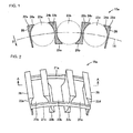
- Fig. 2 is a perspective view showing a retainer segment according to one embodiment of the present invention.
- Fig. 1 is a sectional view showing the retainer segment cut at a section shown by arrows A and A in Fig. 2 .
- a plurality of rollers retained by the retainer segment are shown by dotted lines and connection parts 21a and 21b are not shown for easy understanding.
- a retainer segment 15a comprises four pillar parts 22a, 22b, 22c and 22d extending in an axial direction so as to form two first pockets 23a and 23c and one second pocket 23b for housing the rollers, and the connection parts 21a and 21b extending in a circumferential direction so as to connect the four pillar parts 22a, 22b, 22c and 22d.
- the connection parts 21a and 21b have predetermined curvatures in the circumferential direction such that the plurality of retainer segments 15a and the like are continuously lined with each other in the circumferential direction to form one annular retainer when incorporated in the rolling bearing.
- the retainer segment 15a is provided by cutting and splitting the integrated annular retainer along a split line extending in the axial direction so as to contain the first and second pockets 23a to 23c.
- the plurality of connection parts 21a and 21b are provided in this example, the number of the connection part may be one.
- Outer diameter side roller stopper parts 24a and 24b for limiting the movement of the roller held in the first pocket 23a toward the outer diameter side are provided on the outer diameter side of the pillar parts 22a and 22b positioned on circumferential both sides of the first pocket 23a.
- inner diameter side roller stopper parts 25a and 25b for limiting the movement of the roller held in the second pocket 23b toward the inner diameter side are provided on the inner diameter side of the pillar parts 22b and 22c positioned on circumferential both sides of the second pocket 23b adjacent to the first pocket 23a.
- outer diameter side roller stopper part 24c and 24d for limiting the movement of the roller held in the first pocket 23c toward the outer diameter side are provided on the outer diameter side of the pillar parts 22c and 22d positioned on circumferential both sides of the first pocket 23c adjacent to the second pocket 23b.
- the retainer segment 15a is an independent member, it is likely to be inclined with respect to a PCD 16 in the rolling bearing. However, since the retainer segment 15a has three pockets in total such as two first pockets 23a and 23c on both ends thereof and the one second pocket 23b in the center thereof, the retainer segment 15a is not likely to be inclined with respect to the PCD 16, so that it is stably arranged.
- the pillar part 22b positioned between the first pocket 23a and the second pocket 23b has the outer diameter side roller stopper part 24b on its outer diameter side, and the inner diameter side roller stopper part 25a on its inner diameter side.
- the pillar part 22c positioned between the second pocket 23b and the first pocket 23c has the outer diameter side roller stopper part 24c on its outer diameter side, and the inner diameter side roller stopper part 25b on its inner diameter side.
- Fig. 3 is a sectional view showing one part of a rolling bearing 11 provided with the retainer segment 15a shown in Figs. 1 and 2 .
- the rolling bearing 11 comprises an outer ring 12, and an inner ring 13, a plurality of rollers 14a, 14b and 14c arranged between the outer ring 12 and the inner ring 13, and a plurality of retainer segments 15a and the like for retaining the rollers 14a and the like.
- Retainer segments 15b and 15c adjacent to the retainer segment 15a are arranged in the rolling bearing 11 in the circumferential direction such that they are opposed to outer width faces 26 of the pillar parts 22a and 22d positioned at the outermost ends in the circumferential direction.
- the retainer segment 15a is guided by the rollers, the retainer segment 15a is stably arranged in the radial direction in the rolling bearing 11. Therefore, noise due to the contact between end faces 27 on the radial outer side of the pillar parts 22a to 22d of the retainer segment 15a and an inner diameter surface 17 of the outer ring 12 positioned on the outer diameter side and the contact between end faces 28 of the radial inner side of the pillar parts 22a to 22d thereof and an outer diameter surface 18 of the inner ring 13 positioned on the inner diameter side is prevented. In addition, accordingly, the retainer segment 15a is not likely to be damaged due to the contact with the outer ring 12 and the like.
- the retainer segment 15a has three pockets such as the first and second pockets for housing the rollers in the above embodiment, it may have two or more first pockets and two or more second pockets, that is, four or more pockets in total.
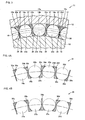
- Figs. 4A and 4B are sectional views each showing a retainer segment having four pockets in total, that is, two first pockets and two second pockets. Referring to Fig.
- a retainer segment 31 comprises a plurality of pillar parts 32a, 32b, 32c, 32d and 32e extending in an axial direction so as to form two first pockets 33a and 33c and two second pockets 33b and 33d, and a connection part (not shown) extending in a circumferential direction so as to connect the plurality of pillar parts 32a, 32b, 32c, 32d and 32e.
- Outer diameter side roller stopper parts 34a, 34b, 34c and 34d for limiting the movement of the roller housed in the first pockets 33a and 33c toward the outer diameter side are provided on the outer diameter side of the pillar parts 32a, 32b, 32c and 32d positioned on circumferential both sides of the first pockets 33a and 33c.
- inner diameter side roller stopper parts 35a, 35b, 35c and 35d for limiting the movement of the roller housed in the second pockets 33b and 33d toward the inner diameter side are provided on the inner diameter side of the pillar parts 32b, 32c, 32d and 32e positioned on circumferential both sides of the second pockets 33b and 33d.
- the outer diameter side roller stopper parts 34a, 34b, 34c and 34d provided in the pillar parts 32a, 32b, 32c and 32d of the two first pockets 33a and 33c that are not adjacent to each other restrict the movement of the retainer segment 31 toward the inner diameter side
- the inner diameter side roller stopper parts 35a, 35b, 35c and 35d provided in the pillar parts 32b, 32c, 32d and 32e of the two second pockets 33b and 33d that are not adjacent to each other restrict the movement of the retainer segment 31 toward the outer diameter side, among the first and second pockets 33a, 33b, 33c and 33d.
- the retainer segment 31 can be further stably arranged and the retainer segment 31 is further not likely to be inclined with respect to the PCD in the rolling bearing.
- a retainer segment 36 has two first pockets 37a and 37d and two second pockets 37b and 37c, in which inner diameter side roller stopper parts provided in pillar parts 38b, 38c and 38d positioned on the circumferential both sides of the adjacent second pockets 37b and 37c restrict the movement toward the outer diameter side, and outer diameter side roller stopper parts provided in pillar parts 38a, 38b, 38d and 38e positioned on the circumferential both sides of the first pockets 37a and 37d positioned on both end sides of the retainer segment 36 restrict the movement toward the inner diameter side.
- the retainer segment 36 can be further stably arranged and the retainer segment 36 is further not likely to be inclined with respect to the PCD in the rolling bearing similar to the above.
- the roller housed in the retainer segment may be a cylindrical roller and a tapered roller whose diameter is gradually increased in the axial direction.
- the distance of the wall surfaces of the pillar parts abutting on the tapered roller in the retainer segment may be gradually increased from the small diameter end face to the large diameter end face of the tapered roller.
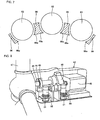
- Fig. 5 is a view showing the rolling bearing
- Fig. 6 is a view showing the retainer segment viewed from arrow C in Fig. 5
- Fig. 7 is a sectional view taken along line D-D in Fig. 5 .
- the rolling bearing is a tapered roller bearing 61 that comprises an inner ring 62, an outer ring (not shown), a plurality of tapered rollers 63 arranged between the inner ring 62 and the outer ring, and a retainer 64 having pockets for housing the plurality of tapered rollers 63.
- the retainer 64 is split into a plurality of retainer segments 64a, ... along a split line extending in an axial direction.
- the inner ring 62 is an annular member and has a large flange 62a and a small flange 62b as flange parts at axial both ends of its outer diameter surface, in which a rolling space is provided between the large flange 62a and the small flange 62b to receive the tapered roller 63.
- Fig. 6 is an enlarged view showing the retainer segment 64a.
- the retainer segment 64a has a pair of ring parts 65a and 65b, and a plurality of pillar parts 66 arranged between the pair of ring parts 65a and 65b and extending in the axial direction so as to form pockets for housing the tapered rollers 63.
- three pockets are formed by the four pillar parts 66, and one tapered roller 63 is housed in each pocket.
- the other retainer segments have the same constitution as that of the retainer segment 64a, their descriptions are omitted.
- Each of the ring parts 65a and 65b is in the form of a circular arc, and has abutment end faces 67 abutting on the adjacent retainer segments at both ends, and inner ring abutment parts 68a and 68b projecting from the inner diameter surfaces of the ring parts 65a and 65b toward the radial inner side as shown in Fig. 5 .
- a circular configuration is formed along the inner ring 62 and the outer ring.
- the curvature radius of the ring part 65a of the tapered roller 63 on the large end face side is set so as to be larger than that of the ring part 65b positioned on the small end face in order to hold the tapered roller 63 appropriately.
- Fig. 7 is the sectional view showing the configuration of the pillar part 66 taken along line D-D in Fig. 5 .
- the inner ring 62 and the ring part 65a are not shown for simplification.
- the end face of the pillar part 66 forming the pocket has a curved configuration along the rolling surface of the tapered roller 63, and a roller stopper part 66a for limiting the movement of the tapered roller 63 toward the inner diameter side is provided at its innermost part.
- the width dimension of the pillar part 66 is increased from the side of the ring part 65b to the ring part 65a, and the pocket has a trapezoidal configuration so as to follow the outline of the tapered roller 63.
- the inner ring abutment part 68a abuts on the large flange 62a of the inner ring 62, and the inner ring abutment part 68b abuts on the small flange 62b of the inner ring 62. Therefore, when the retainer segment 64a is arranged at an uppermost position, the inner ring abutment members 68a and 68b are in contact with the flange parts 62a and 62b and the retainer segment 64a is guided by the inner ring flanges.
- the movement of the retainer segment 64a toward the radial inner side is limited by the inner ring flange parts 62a and 62b, and the movement thereof to the radial outer side is limited by the tapered roller 63, whereby noise and damage of the retainer segment 64a due to the contact between the retainer segment 64a and the inner ring 62 or the outer ring can be prevented.
- the retainer segment 64a does not scrape off the oil film on track surfaces of the inner and outer rings, the rolling bearing is superior in lubrication performance.
- the present invention is not limited to this and can be applied to the case where the abutment end faces 67 do not project from the right and left both ends of the pillar part 66.
- the pillar parts 66 of the adjacent retainer segments are in contact with each other, since the pillar part 66 could be deformed or damaged at the time of rotation of the bearing, it is preferable that the pillar parts 66 of the adjacent retainer segments are not in contact with each other.
- the present example is not limited to this and can be applied to the case where a pocket is formed between the abutment parts of the adjacent retainer segments and the tapered roller may be housed therein. In this case, the load capacity of the tapered roller bearing 61 can be increased.
- the retainer 64 can be formed by combining two or more retainer segments and the number of the rollers housed in each retainer segment can be selected optionally.
- an intermediate element for adjusting a gap may be arranged between the retainer segments to fill the circumferential gap formed between the retainer segments.
- the present example may be applied to a double row tapered roller bearing.
- the present example can be applied to various kinds of rolling bearings such as a self-aligning roller bearing having a spherical roller, and a cylindrical roller bearing having a cylindrical roller.
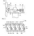
- Figs. 8 and 9 show one example of a main shaft support structure of a wind-power generator in which the above rolling bearing is used as a main shaft support bearing 45.
- a casing 43 of a nacelle 42 for supporting the main part of the main shaft support structure is put on a support table 40 through a slewing bearing 41 at a high position so as to be horizontally turned.
- a blade 47 receiving wind power is fixed to one end of a main shaft 46.
- the main shaft 46 is rotatably supported in the casing 43 of the nacelle 42 through the main shaft support bearing 45 incorporated in a bearing housing 44, and the other end of the main shaft 46 is connected to a speed-up gear 48, and an output shaft of the speed-up gear 48 is coupled to a rotor shaft of a generator 49.
- the nacelle 42 is turned in any angle by a rotation motor 50 through a speed-down gear 51.
- the main shaft support bearing 45 incorporated in the bearing housing 44 is the rolling bearing according to one embodiment of the present invention and comprises the plurality of rollers and the retainer for holding the rollers.
- the retainer is split into the plurality of retainer segments along the split line extending in the axial direction.
- Each retainer segment comprises the plurality of pillar parts extending in the axial direction so as to form the first and second pockets for holding the rollers, and the connection part extending in the circumferential direction so as to connect the plurality of pillar parts.
- the pillar part has the outer diameter side roller stopper part for limiting the movement of the roller housed in the first pocket toward the outer diameter side and the inner diameter side roller stopper part for limiting the movement of the roller housed in the second pocket to the inner diameter side.
- the main shaft support bearing 45 supports the main shaft 46 whose one end is fixed to the blade 47 receiving great wind power, it receives a high load.
- the main shaft support bearing 45 has to be large itself.
- the rolling bearing comprises the retainer segments that can be split, since the productivity, handling property and assembling property of the retainer can be improved, the productivity of the rolling bearing itself can be improved.
- the retainer segment is guided by the roller and it can be stably arranged in the radial direction, it is not likely to be in contact with the outer ring or the inner ring, so that noise due to the contact can be prevented from being generated and the damage due to the contact can be prevented.
- the rolling bearing according to the example as shown in Figs. 6 to 7 may be applied to the main shaft support bearing 45 incorporated in the bearing housing 44.
- the main shaft support bearing 45 supports the main shaft 46 whose one end is fixed to the blade 47 receiving great wind power, it receives a high load.
- the main shaft support bearing 45 has to be large itself.
- the rolling bearing comprises the retainer segments that can be split, since the productivity, handling property and assembling property of the retainer can be improved, the productivity of the rolling bearing itself can be improved.
- the main shaft support structure of the wind-power generator is superior in reliability.
- the present invention is not limited to this and may be applied to the case where the split part is positioned at the connection part.
- the retainer segment is continuously lined with each other at the connection parts.
- the retainer segment 15a is small in size and simple in configuration, when it is formed of a resin by injection molding, it can be easily manufactured. Thus, the productivity thereof can be high.
- connection parts 21a and 21b and the ring parts 65a and 65b of the retainer segment 15a and the like are designed to have predetermined curvatures in the above embodiment.
- the connection parts 21a and 21b and the ring parts 65a and 65b may not have the predetermined curvature at the time of production and may be linearly formed of a flexible resin so as to be elastic in the circumferential direction so as to have the predetermined curvature when incorporated in the rolling bearing.
- the retainer segment 15a and the like can be simpler in configuration at the time of production, so that the productivity thereof is further improved.
- the retainer segment according to the present invention can be stably arranged in the rolling bearing, and the rolling bearing according to the present invention can prevent the contact between the retainer segment and the outer ring and the like, they can be effectively used as the retainer segment and the rolling bearing required to prevent noise.
- the main shaft support structure of the wind-power generator according to the present invention comprises the rolling bearing in which the split type retainer segment can be stably arranged, it can be effectively applied to the case required to be large in size and prevent noise.
- the retainer segment according to the present invention can be advantageously used in the large-size rolling bearing such as the bearing supporting the main shaft of the wind-power generator.
Landscapes
- Engineering & Computer Science (AREA)
- General Engineering & Computer Science (AREA)
- Mechanical Engineering (AREA)
- Life Sciences & Earth Sciences (AREA)
- Sustainable Development (AREA)
- Sustainable Energy (AREA)
- Chemical & Material Sciences (AREA)
- Combustion & Propulsion (AREA)
- Rolling Contact Bearings (AREA)
Claims (7)
- Ein Haltersegment (15a-c, 31, 36), das eine Vielzahl von Rollen (14a, 14b, 14c) hält und entlang einer sich in axialer Richtung erstreckenden Teilungslinie unterteilt ist, wobei
das Haltersegment (15a-c, 31, 36) eine Vielzahl von Stützteilen (22a-d, 32a-e, 38a-e) aufweist, die sich entlang einer axialen Richtung erstrecken und somit eine erste Tasche (23a, 23c, 33a, 33c, 37a, 37d) und eine zweite Tasche (23b, 33b, 33d, 37b, 37c) bilden, um eine Rolle (14a, 14b, 14c) aufzunehmen sowie ein Verbindungsstück (21 a, 21b), das sich entlang einer umlaufenden Richtung erstreckt um die Vielzahl der Stützteile (22a-d, 32a-e, 38a-e) zu verbinden, wobei
ein Stützteil (22b, 22c, 32b-d, 38b, 38d) ein Anschlagteil an der Außendurchmesserseite (24b, 24c, 34b-d) aufweist, das die Bewegung der Rolle (14a, 14c) einschränkt welche in der ersten Tasche (23a, 23c, 33a, 33c, 37a, 37d) hin zur Außendurchmesserseite aufgenommen ist, und ein Rollenanschlagteil an der Innendurchmesserseite (25a, 2b, 35a-d) zur Einschränkung der Bewegung der Rolle (14b) welche in der zweiten Tasche (23b, 33b, 33d, 37b, 37c) hin zur Innendurchmesserseite aufgenommen ist, wobei
die erste Tasche (23a, 23c, 33a, 33c, 37a, 37d) durch gegenüberliegende Wandflächen von benachbarten Stützteilen (22a-d, 32a-d, 38a, 38b, 38d, 38e) definiert ist und die Außendurchmesserseite der gegenüberliegenden Wandflächen mit einem Anschlagteil am Außendurchmesser (24a-d, 34a-d) versehen ist, um eine Rolle (14a), die von der Innendurchmesserseite in die erste Tasche (23a, 23c, 33a, 33c, 37a, 37d) aufgenommen ist, daran zu hindern, sich nach außen hin zur Außendurchmesserseite zu bewegen,
und die zweite Tasche (23b, 33b, 33d, 37b, 37c) durch gegenüberliegende Wandflächen von benachbarten Stützteilen (22b, 22c, 32b-e, 38) definiert ist und die Innendurchmesserseite der gegenüberliegenden Wandflächen mit einem Anschlagteil am Innendurchmesser (25a, 25b, 35a-d) versehen ist, um eine Rolle (14b), die von der Außendurchmesserseite in die zweite Tasche (23b, 33b, 33d, 37b, 37c) aufgenommen ist, daran zu hindern, sich nach außen hin zur Innendurchmesserseite zu bewegen, wobei
die erste Tasche (23a, 23c, 33a, 33c, 37a, 37d) nur mit Anschlagteilen an der Außendurchmesserseite (24a-d, 34a-d) versehen ist und die zweite Tasche (23b, 33b, 33d, 37b, 37c) nur mit Anschlagteilen an der Innendurchmesserseite (25a, 25b, 35a-d). - Ein Wälzlager mit einer Vielzahl von Rollen (14a, 14b, 14c, 63), und einen Halter, der die Vielzahl der Rollen (14a, 14b, 14c, 63) hält, wobei
der Halter entlang einer sich in axialer Richtung erstreckenden Teilungslinie in eine Vielzahl von Haltersegmenten (15a-c, 31, 36, 61, 64a) unterteilt ist,
wobei das Haltersegment (15a-c, 31, 36, 61, 64a) ein Haltersegment (15a-c, 31, 36, 61, 64a) gemäß Anspruch 1 ist. - Wälzlager gemäß Anspruch 2, wobei
das Stützteil (22a-d, 32a-e, 38a-e, 66) zwischen der ersten Tasche (23a, 23c, 33a, 33c, 37a, 37d) und der zweiten Tasche (23b, 33b, 33d, 37b, 37c) angeordnet ist das das Anschlagteil an der Außendurchmesserseite (24a-d, 34a-d) und das Anschlagteil an der Innendurchmesserseite (25a, 25b, 35a-d) aufweist. - Wälzlager gemäß Anspruch 2, wobei
das Haltersegment (15a-c, 31, 36, 61, 64a) mindestens drei Taschen hat. - Wälzlager gemäß Anspruch 2, wobei
das Haltersegment (15a-c, 31, 36, 61, 64a) aus einem Harz gebildet ist. - Wälzlager gemäß Anspruch 2, wobei
die Rolle (14a, 14b, 14c, 63) eine Kegelrolle (63) ist. - Eine Hauptwellenstützstruktur eines Windkraftgenerators mit:einer Klinge (47) um Windkraft aufzunehmen;einer Hauptwelle (46) wobei ein Ende an die Klinge (47) befestigt ist und sich mit der Klinge (47) dreht; undeinem Wälzlager, das in ein Befestigungselement eingebaut ist und die Hauptwelle (46) drehbar stützt, wobeidas Wälzlager eine Vielzahl von Rollen (14a, 14b, 14c, 63) umfasst,und ein Halter die Vielzahl der Rollen (14a, 14b, 14c, 63) hält,wobei der Halter entlang einer sich in axialer Richtung erstreckenden Teilungslinie in eine Vielzahl von Haltersegmenten (15a-c, 31, 36, 61, 64a) unterteilt ist,jedes Haltersegment (15a-c, 31, 36, 61, 64a) ein Haltersegment (15a-c, 31, 36, 61, 64a) gemäß Anspruch 1 ist.
Applications Claiming Priority (3)
| Application Number | Priority Date | Filing Date | Title |
|---|---|---|---|
| JP2005368588A JP4342512B2 (ja) | 2005-12-21 | 2005-12-21 | 転がり軸受、保持器セグメントおよび風力発電機の主軸支持構造 |
| JP2006030088A JP2007211833A (ja) | 2006-02-07 | 2006-02-07 | 転がり軸受、保持器セグメントおよび風力発電機の主軸支持構造 |
| PCT/JP2006/322266 WO2007072637A1 (ja) | 2005-12-21 | 2006-11-08 | 転がり軸受、保持器セグメントおよび風力発電機の主軸支持構造 |
Publications (3)
| Publication Number | Publication Date |
|---|---|
| EP1998059A1 EP1998059A1 (de) | 2008-12-03 |
| EP1998059A4 EP1998059A4 (de) | 2011-07-27 |
| EP1998059B1 true EP1998059B1 (de) | 2014-06-18 |
Family
ID=38188420
Family Applications (1)
| Application Number | Title | Priority Date | Filing Date |
|---|---|---|---|
| EP06823170.3A Active EP1998059B1 (de) | 2005-12-21 | 2006-11-08 | Wälzlager, haltersegment und hauptwellenstützstruktur für windgetriebenen generator |
Country Status (5)
| Country | Link |
|---|---|
| US (1) | US8177437B2 (de) |
| EP (1) | EP1998059B1 (de) |
| DK (1) | DK1998059T3 (de) |
| ES (1) | ES2498974T3 (de) |
| WO (1) | WO2007072637A1 (de) |
Families Citing this family (10)
| Publication number | Priority date | Publication date | Assignee | Title |
|---|---|---|---|---|
| DE112009001651B4 (de) * | 2008-07-08 | 2014-03-06 | Nsk Ltd. | Harzkäfig für Kegelrollenlager und Kegelrollenlager |
| EP2649333B1 (de) * | 2010-12-07 | 2018-05-02 | Aktiebolaget SKF | Käfigsegment eines kegelrollenlagers und kegelrollenlager |
| EP2610512A1 (de) * | 2011-12-28 | 2013-07-03 | Siemens Aktiengesellschaft | Wälzlager |
| CN104254698B (zh) * | 2012-04-23 | 2018-02-09 | Skf公司 | 轴承装置 |
| JP2013241959A (ja) * | 2012-05-18 | 2013-12-05 | Jtekt Corp | 転がり軸受用の分割保持器 |
| JP2013242018A (ja) * | 2012-05-22 | 2013-12-05 | Jtekt Corp | 転がり軸受用の分割保持器及びそれを用いた転がり軸受 |
| EP2940323B1 (de) | 2012-12-25 | 2018-08-15 | NSK Ltd. | Kegelrollenlager |
| US20160040716A1 (en) * | 2013-04-04 | 2016-02-11 | Nsk Ltd. | Resin cage for tapered roller bearing and tapered roller bearing including the resin cage |
| US9541130B2 (en) * | 2013-04-11 | 2017-01-10 | Aktiebolaget Skf | Rolling bearing with rolling bodies disposed in a plurality of cage segments |
| CN105793587B (zh) | 2013-11-22 | 2019-04-12 | 株式会社捷太格特 | 锥形滚子轴承和动力传递装置 |
Family Cites Families (20)
| Publication number | Priority date | Publication date | Assignee | Title |
|---|---|---|---|---|
| FR1303538A (fr) * | 1961-07-31 | 1962-09-14 | Roulements A Aiguilles Sa | Cage segmentée pour roulements à rouleaux ou à aiguilles |
| FR1339859A (fr) * | 1962-11-19 | 1963-10-11 | Roller Bearing Co Of America | Cage indépendante pour retenir des rouleaux de paliers |
| US3477773A (en) * | 1968-01-23 | 1969-11-11 | John A Altson | Molded cage for nonseparable assembly of roller bearings |
| US4239304A (en) * | 1979-03-28 | 1980-12-16 | The Torrington Company | Bearing split cage |
| JPS5737123A (en) | 1980-08-11 | 1982-03-01 | Honda Motor Co Ltd | Clutch device |
| FR2521665A1 (fr) * | 1982-02-18 | 1983-08-19 | Nadella | Cage pour roulement conique a aiguilles ou a rouleaux |
| JPS5950224A (ja) * | 1982-09-16 | 1984-03-23 | Koyo Seiko Co Ltd | 円すいころ軸受用合成樹脂製保持器 |
| JP2554505B2 (ja) | 1987-08-28 | 1996-11-13 | 光洋精工株式会社 | 円すいころ軸受 |
| JPH07108054B2 (ja) | 1987-09-26 | 1995-11-15 | 松下電工株式会社 | 欠相遮断器 |
| DE3841629C2 (de) * | 1988-12-10 | 1996-07-11 | Skf Gmbh | Rollenlagerung |
| JPH0519652A (ja) | 1991-07-08 | 1993-01-29 | Canon Inc | 加熱装置 |
| JPH0589952A (ja) | 1991-09-30 | 1993-04-09 | Dainippon Ink & Chem Inc | 面状発熱体の製造法 |
| JP2000081042A (ja) | 1998-07-10 | 2000-03-21 | Nippon Seiko Kk | 円筒ころ軸受 |
| JP2003013967A (ja) * | 2001-04-24 | 2003-01-15 | Ntn Corp | 旋回軸受用保持器とこれを用いた旋回軸受 |
| JP2002333027A (ja) | 2001-05-09 | 2002-11-22 | Ntn Corp | 超薄肉形転がり軸受 |
| JP2003336645A (ja) | 2002-05-21 | 2003-11-28 | Nsk Ltd | スラスト円筒ころ軸受 |
| JP2004019921A (ja) | 2002-06-20 | 2004-01-22 | Ntn Corp | 超薄肉形転がり軸受 |
| DE10246825B4 (de) | 2002-10-08 | 2019-02-14 | Aktiebolaget Skf | Käfig für ein Wälzlager |
| JP2005147331A (ja) * | 2003-11-18 | 2005-06-09 | Ntn Corp | 複列転がり軸受 |
| JP2005221001A (ja) | 2004-02-05 | 2005-08-18 | Nsk Ltd | 円すいころ軸受 |
-
2006
- 2006-11-08 EP EP06823170.3A patent/EP1998059B1/de active Active
- 2006-11-08 WO PCT/JP2006/322266 patent/WO2007072637A1/ja active Application Filing
- 2006-11-08 US US12/086,856 patent/US8177437B2/en active Active
- 2006-11-08 ES ES06823170.3T patent/ES2498974T3/es active Active
- 2006-11-08 DK DK06823170.3T patent/DK1998059T3/da active
Also Published As
| Publication number | Publication date |
|---|---|
| US20090074345A1 (en) | 2009-03-19 |
| ES2498974T3 (es) | 2014-09-26 |
| DK1998059T3 (da) | 2014-09-22 |
| WO2007072637A1 (ja) | 2007-06-28 |
| EP1998059A4 (de) | 2011-07-27 |
| EP1998059A1 (de) | 2008-12-03 |
| US8177437B2 (en) | 2012-05-15 |
Similar Documents
| Publication | Publication Date | Title |
|---|---|---|
| EP1998059B1 (de) | Wälzlager, haltersegment und hauptwellenstützstruktur für windgetriebenen generator | |
| US10190576B2 (en) | Roller bearing, retainer segment, spacer and main shaft support structure of wind-power generator | |
| US8608387B2 (en) | Roller bearing and main shaft support structure of wind-power generator | |
| CN101341349B (zh) | 滚动轴承、保持器构件及风力发电机主轴支承结构 | |
| US7922396B2 (en) | Double row self-aligning roller bearing and main shaft support structure of wind power generator | |
| JP2007263304A (ja) | ころ軸受、保持器セグメントおよび風力発電機の主軸支持構造 | |
| JP2007211833A (ja) | 転がり軸受、保持器セグメントおよび風力発電機の主軸支持構造 | |
| JP2007285507A (ja) | ころ軸受、保持器セグメント、間座および風力発電機の主軸支持構造 | |
| JP2007247819A (ja) | ころ軸受、保持器セグメントおよび風力発電機の主軸支持構造 | |
| JP5010353B2 (ja) | ころ軸受、ころ軸受の保持器セグメントおよび風力発電機の主軸支持構造 | |
| JP4429265B2 (ja) | ころ軸受および風力発電機の主軸支持構造 | |
| JP2009052746A (ja) | 転がり軸受、保持器セグメントおよび風力発電機の主軸支持構造 | |
| JP2007255534A (ja) | ころ軸受、保持器セグメント、間座および風力発電機の主軸支持構造 | |
| JP2007239948A (ja) | ころ軸受、保持器セグメント、間座および風力発電機の主軸支持構造 | |
| JP4372763B2 (ja) | ころ軸受および風力発電機の主軸支持構造 | |
| JP4177852B2 (ja) | 風力発電機の主軸支持用ころ軸受、保持器セグメント、および風力発電機の主軸支持構造 | |
| JP2007255627A (ja) | ころ軸受、間座および風力発電機の主軸支持構造 | |
| JP4818424B2 (ja) | 風力発電機の主軸支持構造 | |
| JP2008185167A (ja) | ころ軸受、保持器セグメントおよび風力発電機の主軸支持構造 | |
| JP2007285415A (ja) | ころ軸受、間座および風力発電機の主軸支持構造 | |
| JP4177854B2 (ja) | 風力発電機の主軸支持用転がり軸受、および風力発電機の主軸支持構造 | |
| JP2007255603A (ja) | 粉砕ローラならびに粉砕ローラ用ころ軸受およびその組み立て方法 | |
| JP2007239950A (ja) | ころ軸受、保持器セグメントおよび風力発電機の主軸支持構造 | |
| JP2007247817A (ja) | ころ軸受、保持器セグメント、間座および風力発電機の主軸支持構造 |
Legal Events
| Date | Code | Title | Description |
|---|---|---|---|
| PUAI | Public reference made under article 153(3) epc to a published international application that has entered the european phase |
Free format text: ORIGINAL CODE: 0009012 |
|
| 17P | Request for examination filed |
Effective date: 20080619 |
|
| AK | Designated contracting states |
Kind code of ref document: A1 Designated state(s): DE DK ES FR |
|
| DAX | Request for extension of the european patent (deleted) | ||
| RBV | Designated contracting states (corrected) |
Designated state(s): DE DK ES FR |
|
| REG | Reference to a national code |
Ref country code: DE Ref legal event code: R079 Ref document number: 602006041981 Country of ref document: DE Free format text: PREVIOUS MAIN CLASS: F16C0033460000 Ipc: F03D0011000000 |
|
| A4 | Supplementary search report drawn up and despatched |
Effective date: 20110629 |
|
| RIC1 | Information provided on ipc code assigned before grant |
Ipc: F03D 11/00 20060101AFI20110622BHEP Ipc: F16C 19/36 20060101ALI20110622BHEP Ipc: F16C 33/51 20060101ALI20110622BHEP |
|
| 17Q | First examination report despatched |
Effective date: 20110705 |
|
| REG | Reference to a national code |
Ref country code: DE Ref legal event code: R079 Ref document number: 602006041981 Country of ref document: DE Free format text: PREVIOUS MAIN CLASS: F03D0011000000 Ipc: F16C0033460000 |
|
| RIC1 | Information provided on ipc code assigned before grant |
Ipc: F03D 11/00 20060101ALI20131203BHEP Ipc: F16C 33/51 20060101ALI20131203BHEP Ipc: F16C 33/46 20060101AFI20131203BHEP Ipc: F16C 19/36 20060101ALI20131203BHEP |
|
| GRAP | Despatch of communication of intention to grant a patent |
Free format text: ORIGINAL CODE: EPIDOSNIGR1 |
|
| INTG | Intention to grant announced |
Effective date: 20140121 |
|
| GRAS | Grant fee paid |
Free format text: ORIGINAL CODE: EPIDOSNIGR3 |
|
| GRAA | (expected) grant |
Free format text: ORIGINAL CODE: 0009210 |
|
| AK | Designated contracting states |
Kind code of ref document: B1 Designated state(s): DE DK ES FR |
|
| REG | Reference to a national code |
Ref country code: DE Ref legal event code: R096 Ref document number: 602006041981 Country of ref document: DE Effective date: 20140724 |
|
| REG | Reference to a national code |
Ref country code: DK Ref legal event code: T3 Effective date: 20140915 |
|
| REG | Reference to a national code |
Ref country code: ES Ref legal event code: FG2A Ref document number: 2498974 Country of ref document: ES Kind code of ref document: T3 Effective date: 20140926 |
|
| REG | Reference to a national code |
Ref country code: DE Ref legal event code: R097 Ref document number: 602006041981 Country of ref document: DE |
|
| PLBE | No opposition filed within time limit |
Free format text: ORIGINAL CODE: 0009261 |
|
| STAA | Information on the status of an ep patent application or granted ep patent |
Free format text: STATUS: NO OPPOSITION FILED WITHIN TIME LIMIT |
|
| 26N | No opposition filed |
Effective date: 20150319 |
|
| REG | Reference to a national code |
Ref country code: FR Ref legal event code: PLFP Year of fee payment: 10 |
|
| REG | Reference to a national code |
Ref country code: FR Ref legal event code: PLFP Year of fee payment: 11 |
|
| REG | Reference to a national code |
Ref country code: FR Ref legal event code: PLFP Year of fee payment: 12 |
|
| REG | Reference to a national code |
Ref country code: FR Ref legal event code: PLFP Year of fee payment: 13 |
|
| PGFP | Annual fee paid to national office [announced via postgrant information from national office to epo] |
Ref country code: DK Payment date: 20221111 Year of fee payment: 17 |
|
| PGFP | Annual fee paid to national office [announced via postgrant information from national office to epo] |
Ref country code: FR Payment date: 20230929 Year of fee payment: 18 |
|
| PGFP | Annual fee paid to national office [announced via postgrant information from national office to epo] |
Ref country code: ES Payment date: 20231201 Year of fee payment: 18 |
|
| PGFP | Annual fee paid to national office [announced via postgrant information from national office to epo] |
Ref country code: DE Payment date: 20230929 Year of fee payment: 18 |