EP1997698A2 - Dispositif de commutation d'ignition - Google Patents
Dispositif de commutation d'ignition Download PDFInfo
- Publication number
- EP1997698A2 EP1997698A2 EP20080009645 EP08009645A EP1997698A2 EP 1997698 A2 EP1997698 A2 EP 1997698A2 EP 20080009645 EP20080009645 EP 20080009645 EP 08009645 A EP08009645 A EP 08009645A EP 1997698 A2 EP1997698 A2 EP 1997698A2
- Authority
- EP
- European Patent Office
- Prior art keywords
- shutter
- case
- key
- switch device
- ignition switch
- Prior art date
- Legal status (The legal status is an assumption and is not a legal conclusion. Google has not performed a legal analysis and makes no representation as to the accuracy of the status listed.)
- Granted
Links
Images


Classifications
-
- F—MECHANICAL ENGINEERING; LIGHTING; HEATING; WEAPONS; BLASTING
- F02—COMBUSTION ENGINES; HOT-GAS OR COMBUSTION-PRODUCT ENGINE PLANTS
- F02N—STARTING OF COMBUSTION ENGINES; STARTING AIDS FOR SUCH ENGINES, NOT OTHERWISE PROVIDED FOR
- F02N11/00—Starting of engines by means of electric motors
-
- B—PERFORMING OPERATIONS; TRANSPORTING
- B60—VEHICLES IN GENERAL
- B60R—VEHICLES, VEHICLE FITTINGS, OR VEHICLE PARTS, NOT OTHERWISE PROVIDED FOR
- B60R25/00—Fittings or systems for preventing or indicating unauthorised use or theft of vehicles
- B60R25/01—Fittings or systems for preventing or indicating unauthorised use or theft of vehicles operating on vehicle systems or fittings, e.g. on doors, seats or windscreens
- B60R25/04—Fittings or systems for preventing or indicating unauthorised use or theft of vehicles operating on vehicle systems or fittings, e.g. on doors, seats or windscreens operating on the propulsion system, e.g. engine or drive motor
-
- B—PERFORMING OPERATIONS; TRANSPORTING
- B60—VEHICLES IN GENERAL
- B60R—VEHICLES, VEHICLE FITTINGS, OR VEHICLE PARTS, NOT OTHERWISE PROVIDED FOR
- B60R25/00—Fittings or systems for preventing or indicating unauthorised use or theft of vehicles
- B60R25/20—Means to switch the anti-theft system on or off
- B60R25/2063—Ignition switch geometry
-
- E—FIXED CONSTRUCTIONS
- E05—LOCKS; KEYS; WINDOW OR DOOR FITTINGS; SAFES
- E05B—LOCKS; ACCESSORIES THEREFOR; HANDCUFFS
- E05B17/00—Accessories in connection with locks
- E05B17/002—Weather or dirt protection
-
- E—FIXED CONSTRUCTIONS
- E05—LOCKS; KEYS; WINDOW OR DOOR FITTINGS; SAFES
- E05B—LOCKS; ACCESSORIES THEREFOR; HANDCUFFS
- E05B17/00—Accessories in connection with locks
- E05B17/14—Closures or guards for keyholes
- E05B17/18—Closures or guards for keyholes shaped as lids or slides
- E05B17/185—Closures or guards for keyholes shaped as lids or slides pivoting about an axis perpendicular to the lock face
-
- F—MECHANICAL ENGINEERING; LIGHTING; HEATING; WEAPONS; BLASTING
- F02—COMBUSTION ENGINES; HOT-GAS OR COMBUSTION-PRODUCT ENGINE PLANTS
- F02N—STARTING OF COMBUSTION ENGINES; STARTING AIDS FOR SUCH ENGINES, NOT OTHERWISE PROVIDED FOR
- F02N15/00—Other power-operated starting apparatus; Component parts, details, or accessories, not provided for in, or of interest apart from groups F02N5/00 - F02N13/00
-
- Y—GENERAL TAGGING OF NEW TECHNOLOGICAL DEVELOPMENTS; GENERAL TAGGING OF CROSS-SECTIONAL TECHNOLOGIES SPANNING OVER SEVERAL SECTIONS OF THE IPC; TECHNICAL SUBJECTS COVERED BY FORMER USPC CROSS-REFERENCE ART COLLECTIONS [XRACs] AND DIGESTS
- Y10—TECHNICAL SUBJECTS COVERED BY FORMER USPC
- Y10S—TECHNICAL SUBJECTS COVERED BY FORMER USPC CROSS-REFERENCE ART COLLECTIONS [XRACs] AND DIGESTS
- Y10S70/00—Locks
- Y10S70/30—Switch lock
-
- Y—GENERAL TAGGING OF NEW TECHNOLOGICAL DEVELOPMENTS; GENERAL TAGGING OF CROSS-SECTIONAL TECHNOLOGIES SPANNING OVER SEVERAL SECTIONS OF THE IPC; TECHNICAL SUBJECTS COVERED BY FORMER USPC CROSS-REFERENCE ART COLLECTIONS [XRACs] AND DIGESTS
- Y10—TECHNICAL SUBJECTS COVERED BY FORMER USPC
- Y10T—TECHNICAL SUBJECTS COVERED BY FORMER US CLASSIFICATION
- Y10T70/00—Locks
- Y10T70/50—Special application
- Y10T70/5889—For automotive vehicles
- Y10T70/5956—Steering mechanism with switch
-
- Y—GENERAL TAGGING OF NEW TECHNOLOGICAL DEVELOPMENTS; GENERAL TAGGING OF CROSS-SECTIONAL TECHNOLOGIES SPANNING OVER SEVERAL SECTIONS OF THE IPC; TECHNICAL SUBJECTS COVERED BY FORMER USPC CROSS-REFERENCE ART COLLECTIONS [XRACs] AND DIGESTS
- Y10—TECHNICAL SUBJECTS COVERED BY FORMER USPC
- Y10T—TECHNICAL SUBJECTS COVERED BY FORMER US CLASSIFICATION
- Y10T70/00—Locks
- Y10T70/70—Operating mechanism
- Y10T70/7441—Key
- Y10T70/7915—Tampering prevention or attack defeating
- Y10T70/7955—Keyhole guards
-
- Y—GENERAL TAGGING OF NEW TECHNOLOGICAL DEVELOPMENTS; GENERAL TAGGING OF CROSS-SECTIONAL TECHNOLOGIES SPANNING OVER SEVERAL SECTIONS OF THE IPC; TECHNICAL SUBJECTS COVERED BY FORMER USPC CROSS-REFERENCE ART COLLECTIONS [XRACs] AND DIGESTS
- Y10—TECHNICAL SUBJECTS COVERED BY FORMER USPC
- Y10T—TECHNICAL SUBJECTS COVERED BY FORMER US CLASSIFICATION
- Y10T70/00—Locks
- Y10T70/80—Parts, attachments, accessories and adjuncts
- Y10T70/8432—For key-operated mechanism
- Y10T70/8649—Keyhole covers
Definitions
- the present invention relates to an ignition switch device which is disposed in a driver's seat of an industrial machine to start and stop an engine of the industrial machine.
- An industrial machine for example, a construction machine is used in a worksite of engineering works and construction, and includes bulldozers, power shovels, and crane vehicles.
- An ignition switch device for starting and stopping an engine of the industrial machine is disposed in the driver's seat of such an industrial machine. By rotationally operating an ignition key while inserting the key into a key hole of such an ignition switch device, the engine is started and stopped.
- the industrial machine is typically used in the open air in a construction site.
- a shutter in order to prevent muddy water, dust, etc. from entering the key hole, it is desirable that the key hole is provided with a shutter.
- the shutter is brought into a closed state where it covers the key hole, for example, in the surface of the case. In this state, the shutter can prevent muddy water, dust, etc. from entering the keyhole.
- the shutter In the starting operation or stopping operation of the engine, the shutter is rotated about a rotary shaft on the surface of the case to allow the key hole to face the outside so that the ignition key can be inserted into the key hole.
- One or more embodiments of the invention provide an ignition switch device which allows smooth rotation of a shutter to be performed, and which can keep the surface of a case from being scratched, thereby maintaining design quality.
- an ignition switch device disposed in a driver's seat of an industrial machine to start and stop an engine of the industrial machine is provided with: a switching means having a key hole allowing a regular ignition key to be inserted thereinto, and capable of being rotationally operated in a predetermined direction with the ignition key inserted to start and stop the engine of the industrial machine; a case covering the switching means and formed with an insertion hole allowing the key hole to face the outside; a shutter disposed on the surface of the case, and rotatable between a closed position where the insertion hole of the case is closed, and an open position where the insertion hole is opened to allow the key hole to face outside; and a protruding portion formed within the range of rotation of the shutter while protruding from the surface of the case and whose protruding end contacts a rear surface of the shutter while the shutter rotates.
- the protruding portion in the ignition switch device of the first aspect, may be formed such that its protruding end is sharpened.
- a convex shape may be formed along a contour edge of the rear surface of the shutter.
- the protruding portion may be formed so as to extend in an arc along the locus of rotation of the shutter.
- the ignition switch device provided with the protruding portion which is formed within the range of rotation of the shutter while protruding from the surface of the case and whose protruding end contacts a rear surface of the shutter while the shutter rotates.
- smooth rotation of the shutter can be performed, and the surface of the case can be kept from being scratched, thereby maintaining design quality. That is, during the rotation of the shutter, the rear surface of the shutter will contact only the protruding end of the protruding portion. As a result, a place to which any scratches are given will be limited, and the scratches will not be conspicuous. Therefore, the design quality of the surface of the case can be maintained.
- the protruding portion is formed such that its protruding end is sharpened.
- the rear surface of the shutter will contact only the sharpened protruding end of the protruding portion.
- a place where any scratches are given will be limited, and will not be conspicuous. Therefore, the design quality of the surface of the case can be maintained more reliably.
- the convex shape is formed along the contour edge of the rear surface of the shutter.
- the contact area therebetween can be reduced to further keep the rear surface of the case from being scratched.
- the contact area therebetween is small and the frozen place is extremely limited.
- the shutter can be rotated with slight force.
- the protruding portion is formed so as to extend in an arc along the locus of rotation of the shutter.
- a three-dimensional design can be provided so as to indicate the rotation direction of the shutter 4, and the rotational operation of the shutter can be made smoother.
- An ignition switch device related to the present embodiment is disposed in driver' s seats of industrial machines (construction machines), such as bulldozers, power shovels, or crane vehicles to be used in worksites of engineering works or construction.
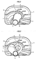
- the ignition switch device is mainly composed of a switching means 2, a case 3, a shutter 4, a main guide shape 5, an auxiliary guide shape 6, and a protruding portion 7.
- the switching means 2 includes a key hole 2a (refer to Fig. 3 ) which allows a regular ignition key K to be inserted thereinto, and can be operated to rotate in a predetermined direction with the ignition key K inserted thereinto to thereby start and stop the engine of an industrial machine.
- the switching means 2 constitutes a cylinder lock in which a plurality of tumblers are provided within the key hole 2a, or a versatile ignition switch including a switch board or the like which can be switched by forming or breaking a predetermined electric circuit by the rotation of the cylinder lock.
- the ignition key K is formed in the shape of a key while its tip (protruding end) Ka is formed in the shape of V, and is configured such that, if the ignition key is a regular one, the shape of the key matches the shape of the tumblers of the cylinder lock in the switching means 2 so that the cylinder lock can be rotated.
- reference numeral Kb denotes a gripping portion of the ignition key K, and a driver grips the gripping portion Kb to operate the ignition key K.
- the case 3 is formed with an insertion hole 3b which allows the key hole 2a to face outside while covering an upper portion of the switching means 2, and printed letters or the like which indicate the position of the ignition key K is given to a surface 3a of the case.
- the case 3 is a resin-molded product obtained by molding predetermined resin (PBT or the like), and various shapes, such as the main guide shape 5, the auxiliary guide shape 6, and the protruding portion 7, which will be explained in detail, are built in the surface of the case at the time of manufacture.
- the shutter 4 is made of metal or resin disposed on the surface 3a of the case 3. As shown in Figs. 2 and 3 , the shutter is adapted to be rotatable about a rotary shaft L between a closed position (position shown in Fig. 2 ) where the insertion hole 3b of the case 3 is closed, and an open position (position shown in Fig. 3 ) where the insertion hole 3b is opened to allow the key hole 2a to face the outside (the upside). Thereby, when such a shutter 4 is in the closed position, the shutter can cover the key hole 2a to prevent muddy water, dust, etc. from entering the key hole.
- the shutter 4 is biased in a direction in which the shutter is always in the closed position by a spring (torsion coil spring or the like biased toward the closed position) which is not shown.
- a spring tilt coil spring or the like biased toward the closed position
- the main guide shape 5 is composed of a groove having a V-shaped cross-section, which is formed in the surface 3a of the case 3, and extends toward the insertion hole 3b (strictly speaking, cutout 4a of the shutter 4 which covers the insertion hole 3b) so that it can guide the tip Ka of the ignition key K to the key hole 2a.
- the main guide shape 5 extends substantially linearly to the insertion hole 3b from the edge of the case 3, and is configured such that its width becomes narrow toward the insertion hole 3b from the edge.
- the auxiliary guide shape 6 is formed on the surface 3a of the case 3 along a contour edge of the shutter 4, and extends toward the main guide shape 5 so that it can guide the tip Ka of the ignition key K to the main guide shape 5. That is, an upper (the side where printed letters are given) contour edge in the shutter 4 is formed in a circular arc as shown in the drawing, and the tip of the auxiliary guide shape communicates with the main guide shape 5 while the auxiliary guide shape 6 is formed along such a circular are.
- the tip Ka of the ignition key K is moved along the auxiliary guide shape 6, it reaches the main guide shape 5 from which it can be guided to the insertion hole 3b as described above.
- a circular-arc cutout 4a which allows the tip Ka of the ignition key K guided by the main guide shape 5 to abut thereon is formed in a position on an extension of the main guide shape 5 of the shutter 4. Also, as shown in Fig. 5 , if the tip Ka of the ignition key K guided by the main guide shape 5 is made to abut on the cutout 4a, and thereafter further moved in this direction, the tip Ka presses the shutter 4 via the cutout 4a so that the shutter 4 can be rotated about the rotary shaft L.
- the cutout 4a and the key hole 2a are set so as to be parallel to each other, and the tip Ka of the ignition key K which is pressing the cutout 4a is configured so as to match the formation position of the key hole 2a.
- the tip Ka of the ignition key K will match the key hole 2a. If the ignition key K is pushed into the switching means 2 from this state, the key can be inserted into the key hole 2a.
- the switching means 2 can be operated to start the engine of the industrial machine. Further, if the ignition key K is rotated in an opposite direction (left direction in the present embodiment) in order to stop the engine of the industrial machine, the switching means 2 can be operated to stop the engine.
- the shutter 4 since the shutter 4 is biased toward the closed position at the time of the rotation of the ignition key K as described above, the cutout 4a and the ignition key K are in an abutting state. However, since the cutout 4a is formed in a circular arc, the rotational operation of the ignition key K can be smoothly performed. Also, if the ignition key K is pulled out of the key hole 2a, as already mentioned, the shutter 4 will be rotated to the closed position and naturally closed by the biasing force of the spring.
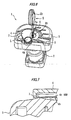
- the protruding portion 7 is formed within the range of rotation of the shutter 4 while protruding from the surface 3a of the case 3, and as shown in Fig. 7 , the protruding portion is set such that its protruding end contacts a rear surface 4b of the shutter 4 while the shutter 4 rotates. As shown in this drawing, the protruding portion 7 is formed such that its protruding end is sharpened, and is configured such that the contact surface thereof with the rear surface 4b of the shutter 4 becomes linear.
- a convex shape 4c is formed along the contour edge in the rear surface 4b of the shutter 4 related to the present embodiment.
- a convex shape 4c is a shape obtained by forming the shutter 4 such that portions other than the contour edge is thinned, and the protruding end of the convex shape is made flat while the height dimension of the convex shape is made uniform.
- the protruding end of the convex shape 4c will also constitute a portion of the rear surface 4b of the shutter 4.
- the shutter 4 will rotate while making the rear surface 4b (protruding end of the convex shape 4c) thereof contact the protruding end of the protruding portion 7.
- smooth rotation of the shutter 4 can be performed, and the surface 3a of the case 3 can be kept from being scratched, thereby maintaining design quality. That is, during the rotation of the shutter 4, the rear surface 4b of the shutter 4 will contact only the protruding end of the protruding portion 7. As a result, a place to which any scratches are given will be limited, and the scratches will not be conspicuous. Therefore, the design quality of the surface 3a of the case 3 can be maintained.
- the shutter 4 prevents a gutter or the like from being generated, and makes it possible to perform more smooth rotation over a prolonged period of time.
- the protruding portion 7 related to the present embodiment is formed such that its protruding end is sharpened.
- the rear surface 4b (protruding end of the convex shape 4c) of the shutter 4 will contact only the sharpened protruding end of the protruding portion 7. As a result, even if any scratches are given, they will not be conspicuous. Therefore, the design quality of the surface 3a of the case 3 can be maintained more reliably.
- the convex shape 4c is formed along the contour edge of the rear surface 4b of the shutter 4.
- the contact area therebetween can be reduced to further keep the surface 3a of the case 3 from being scratched.
- the contact area therebetween is small and the frozen place is extremely limited.
- the shutter 4 can be rotated with slight force.
- the protruding portion 7 is formed so as to extend in an arc along the locus of rotation of the shutter 4.
- a three-dimensional design can be provided so as to indicate the rotation direction of the shutter 4, and the rotational operation of the shutter can be made smoother.
- the protruding portion to be formed in the surface 3a of the case 3 has only to be formed within the range of rotation of the shutter 4, and may be formed so as to extend substantially linearly.
- a driver who is going to start the engine finds the key hole not with his/her eyes, but with his/her hand. If the tip Ka of the ignition key K abuts on the surface 3a of the case 3, is suitably moved along the surface 3a as it is, and thereby inserted into the main guide shape 5 or the auxiliary guide shape 6, the tip Ka is guided to the shutter 4 which covers the insertion hole 3b along the main guide shape 5 and the auxiliary guide shape 6. Then, if the tip is further moved in this direction from the state where it abuts on the cutout 4a of the shutter 4, the shutter 4 can be rotated and be guided to the key hole 2a.
- the invention is not limited thereto.
- the main guide shape 5 and the auxiliary guide 6 may not be formed, but only the protruding portion 7 may be formed with the range of rotationof the shutter 4.
- the convex shape 4c formed along the contour shape is formed in the rear surface 4b of the shutter 4.
- the rear surface 4b of the shutter 4 may be flat.
- the protruding portion 7 is formed such that its protruding end is sharpened, the protruding end may have a flat shape having a minute width. Even in this case, during the rotation of the shutter, the rear surface of the shutter will contact only the protruding end of the protruding portion. As a result, a place where any scratches are given will be limited to the minute width of the protruding end, and the scratches will not be conspicuous. Therefore, the design quality of the surface 3a of the case 3 can be maintained.
- industrial machines to which the invention can be applied include, for example, various machines, such as bulldozers, scrape dozers, hydraulic shovels (backhoes, power shovels, etc.), and tractors with a crane apparatus.
- the invention can also be applied to ones whose appearance shapes are different or to ones to which other functions are added so long as it is an ignition switch device provided with the protruding portion which is formed within the range of rotation of the shutter while protruding from the surface of the case and whose protruding end contacts a rear surface of the shutter while the shutter rotates.
Landscapes
- Engineering & Computer Science (AREA)
- Mechanical Engineering (AREA)
- Chemical & Material Sciences (AREA)
- Combustion & Propulsion (AREA)
- General Engineering & Computer Science (AREA)
- Rotary Switch, Piano Key Switch, And Lever Switch (AREA)
- Lock And Its Accessories (AREA)
- Ignition Installations For Internal Combustion Engines (AREA)
Applications Claiming Priority (1)
| Application Number | Priority Date | Filing Date | Title |
|---|---|---|---|
| JP2007140471A JP4994953B2 (ja) | 2007-05-28 | 2007-05-28 | イグニッションスイッチ装置 |
Publications (3)
| Publication Number | Publication Date |
|---|---|
| EP1997698A2 true EP1997698A2 (fr) | 2008-12-03 |
| EP1997698A3 EP1997698A3 (fr) | 2011-06-01 |
| EP1997698B1 EP1997698B1 (fr) | 2012-06-27 |
Family
ID=39743866
Family Applications (1)
| Application Number | Title | Priority Date | Filing Date |
|---|---|---|---|
| EP20080009645 Active EP1997698B1 (fr) | 2007-05-28 | 2008-05-27 | Dispositif de commutation d'ignition |
Country Status (5)
| Country | Link |
|---|---|
| US (1) | US7707863B2 (fr) |
| EP (1) | EP1997698B1 (fr) |
| JP (1) | JP4994953B2 (fr) |
| KR (1) | KR101148629B1 (fr) |
| CN (1) | CN101315845B (fr) |
Cited By (2)
| Publication number | Priority date | Publication date | Assignee | Title |
|---|---|---|---|---|
| ES2377283A1 (es) * | 2010-06-01 | 2012-03-26 | Cofunco S.A. | Dispositivo de cubrimiento, cierre y similares. |
| CN102393991A (zh) * | 2011-08-26 | 2012-03-28 | 周琪 | 车辆闭锁器 |
Families Citing this family (7)
| Publication number | Priority date | Publication date | Assignee | Title |
|---|---|---|---|---|
| JP5460295B2 (ja) * | 2009-12-21 | 2014-04-02 | 朝日電装株式会社 | シリンダ錠の保護装置 |
| JP6348824B2 (ja) * | 2014-11-07 | 2018-06-27 | 株式会社ホンダロック | シリンダ錠用保護装置 |
| CN105575714A (zh) * | 2015-12-23 | 2016-05-11 | 瑞安市钢铭机车部件有限公司 | 多保护式点火锁 |
| US9587416B1 (en) * | 2016-07-27 | 2017-03-07 | Federal Lock Co., Ltd. | Lock with a slide for covering lock core |
| US9631398B1 (en) * | 2016-07-27 | 2017-04-25 | Federal Lock Co., Ltd. | Lock with a slide for covering lock core and positioning device for the slide |
| US10738513B2 (en) * | 2016-12-09 | 2020-08-11 | Toyota Motor Engineering & Manufacturing North America, Inc. | Flush power slide door handle |
| US11927293B2 (en) | 2021-12-17 | 2024-03-12 | Cnh Industrial America Llc | Coupler door push button release for agricultural vehicle |
Citations (2)
| Publication number | Priority date | Publication date | Assignee | Title |
|---|---|---|---|---|
| DE102004053812A1 (de) | 2003-11-07 | 2005-07-21 | Hitachi Construction Machinery Co., Ltd. | Arbeitsfahrzeug, in dem das Ausmaß gesteuert werden kann, in dem eine Bedienungsperson mit Vibrationen beaufschlagt wird, und Verfahren zum Steuern des Vibrationsbeaufschlagungsausmaßes |
| JP2007140471A (ja) | 2005-11-23 | 2007-06-07 | Samsung Sdi Co Ltd | ウィンドウ組立体が具備された表示素子及びこれを含む携帯用端末 |
Family Cites Families (36)
| Publication number | Priority date | Publication date | Assignee | Title |
|---|---|---|---|---|
| US1088237A (en) * | 1913-03-01 | 1914-02-24 | Rufus K Mulford | Key-guide. |
| US1112485A (en) * | 1913-07-08 | 1914-10-06 | Charles R Snyder | Escutcheon-plate. |
| US1206611A (en) * | 1916-03-28 | 1916-11-28 | George H Strode | Switch-lock. |
| US1718723A (en) * | 1928-03-26 | 1929-06-25 | Williams Harry | Padlock |
| US1904882A (en) * | 1929-04-20 | 1933-04-18 | August F W Viehweger | Burglarproof lock |
| US2355300A (en) * | 1942-01-22 | 1944-08-08 | Yale & Towne Mfg Co | Keyhole cover and assembly |
| US2388228A (en) * | 1944-05-25 | 1945-10-30 | Yale & Towne Mfg Co | Keyhole cover |
| US2400229A (en) * | 1945-05-12 | 1946-05-14 | Henry D Freeman | Lock |
| US2439978A (en) * | 1945-11-21 | 1948-04-20 | Anton W Konchan | Keyhole cover |
| US2562038A (en) * | 1950-01-30 | 1951-07-24 | Briggs & Stratton Corp | Cover for door locks |
| US2602319A (en) * | 1950-07-31 | 1952-07-08 | Briggs & Stratton Corp | Dust cover mounting for cylinder locks |
| US2702468A (en) * | 1951-05-05 | 1955-02-22 | Yale & Towne Mfg Co | Dust cover for locks |
| US2660877A (en) * | 1951-07-30 | 1953-12-01 | Abraham M Malouf | Keyhole cover for lock caps |
| US2658151A (en) * | 1951-10-24 | 1953-11-03 | Heinz Bernard | Luminous lock attachment |
| US2993362A (en) * | 1958-12-29 | 1961-07-25 | Jack A Baccolla | Key guide for locks |
| US3564744A (en) * | 1969-02-20 | 1971-02-23 | Alvin L Shook | Automotive safety signal device |
| US3564880A (en) * | 1969-08-27 | 1971-02-23 | Gen Motors Corp | Door latch control mechanism |
| US3583185A (en) * | 1969-11-03 | 1971-06-08 | Briggs & Stratton Corp | Key-controlled lock switch with reliable weather protection cover |
| US3930391A (en) * | 1975-03-17 | 1976-01-06 | General Motors Corporation | Lock cylinder cover with key engagement release |
| US4231240A (en) * | 1978-07-28 | 1980-11-04 | Nissan Shatai Kabushiki Kaisha | Screw plug assembly |
| US4586355A (en) * | 1985-03-28 | 1986-05-06 | General Motors Corporation | Lock cylinder cover with key engagement release of hold-open detent |
| JPH0330532Y2 (fr) * | 1985-06-24 | 1991-06-27 | ||
| US4773242A (en) * | 1988-02-17 | 1988-09-27 | General Motors Corporation | Lock cylinder cover with time delay closure |
| US5477713A (en) * | 1994-03-29 | 1995-12-26 | Edward Roddy, III | Key orientation system |
| US5680095A (en) * | 1994-12-08 | 1997-10-21 | Gordon Hartunian | Security apparatus |
| JPH09105252A (ja) * | 1995-10-12 | 1997-04-22 | Central Motor Co Ltd | キーシリンダー周りの排水構造 |
| US5718137A (en) * | 1996-08-30 | 1998-02-17 | Huston; Fred Michael | Fork lock cover |
| DE19929243B4 (de) * | 1999-06-25 | 2014-11-06 | Volkswagen Ag | Anordnung mit einem Emblem und einem Schließzylinder eines Kraftfahrzeug-Haubenverschlusses |
| US6272890B1 (en) * | 1999-08-27 | 2001-08-14 | Fred Michael Huston | Fork lock cover for motorcycle mounted with tape and method |
| DE20016845U1 (de) * | 2000-09-29 | 2000-11-30 | Kruse Sicherheitssysteme GmbH & Co. KG, 21435 Stelle | Abdeckung zum Sichern von Schließzylindern |
| JP2003104172A (ja) * | 2001-09-28 | 2003-04-09 | Tetsuo Kuramochi | 車両の盗難防止装置 |
| US20050193788A1 (en) * | 2004-03-03 | 2005-09-08 | Alan Weiner | Method and apparatus locating a keyhole and orienting a key to the keyhole |
| JP4271167B2 (ja) * | 2005-06-24 | 2009-06-03 | 川崎重工業株式会社 | 燃料タンクのタンクキャップ |
| US7401484B1 (en) * | 2005-11-22 | 2008-07-22 | The Eastern Company | Low profile, lockable handle, housing and cover assembly |
| CN2854004Y (zh) | 2005-12-27 | 2007-01-03 | 重庆隆鑫工业(集团)有限公司 | 防盗发动机的带防尘盖锁具组合 |
| CN2900303Y (zh) | 2006-06-08 | 2007-05-16 | 浙江瑞泰动力有限公司 | 摩托车点火开关 |
-
2007
- 2007-05-28 JP JP2007140471A patent/JP4994953B2/ja active Active
-
2008
- 2008-05-26 KR KR1020080048669A patent/KR101148629B1/ko active Active
- 2008-05-27 EP EP20080009645 patent/EP1997698B1/fr active Active
- 2008-05-28 CN CN2008101001788A patent/CN101315845B/zh active Active
- 2008-05-28 US US12/128,205 patent/US7707863B2/en active Active
Patent Citations (2)
| Publication number | Priority date | Publication date | Assignee | Title |
|---|---|---|---|---|
| DE102004053812A1 (de) | 2003-11-07 | 2005-07-21 | Hitachi Construction Machinery Co., Ltd. | Arbeitsfahrzeug, in dem das Ausmaß gesteuert werden kann, in dem eine Bedienungsperson mit Vibrationen beaufschlagt wird, und Verfahren zum Steuern des Vibrationsbeaufschlagungsausmaßes |
| JP2007140471A (ja) | 2005-11-23 | 2007-06-07 | Samsung Sdi Co Ltd | ウィンドウ組立体が具備された表示素子及びこれを含む携帯用端末 |
Cited By (3)
| Publication number | Priority date | Publication date | Assignee | Title |
|---|---|---|---|---|
| ES2377283A1 (es) * | 2010-06-01 | 2012-03-26 | Cofunco S.A. | Dispositivo de cubrimiento, cierre y similares. |
| CN102393991A (zh) * | 2011-08-26 | 2012-03-28 | 周琪 | 车辆闭锁器 |
| CN102393991B (zh) * | 2011-08-26 | 2013-06-05 | 周琪 | 车辆闭锁器 |
Also Published As
| Publication number | Publication date |
|---|---|
| JP2008291587A (ja) | 2008-12-04 |
| US7707863B2 (en) | 2010-05-04 |
| CN101315845B (zh) | 2011-09-28 |
| JP4994953B2 (ja) | 2012-08-08 |
| EP1997698A3 (fr) | 2011-06-01 |
| KR101148629B1 (ko) | 2012-05-23 |
| US20080296468A1 (en) | 2008-12-04 |
| EP1997698B1 (fr) | 2012-06-27 |
| CN101315845A (zh) | 2008-12-03 |
| KR20080104975A (ko) | 2008-12-03 |
Similar Documents
| Publication | Publication Date | Title |
|---|---|---|
| EP1997698B1 (fr) | Dispositif de commutation d'ignition | |
| EP1997987B1 (fr) | Dispositif de commutation d'ignition | |
| US7735347B2 (en) | Ignition switch device | |
| EP2047435B1 (fr) | Dispositif d'actionnement mobile | |
| DE19509003A1 (de) | Herausnehmbares elektronisches Gerät | |
| JP6423504B1 (ja) | 平型導体用コネクタ | |
| EP1783015B1 (fr) | Dispositif electrique de blocage de direction | |
| JP2009228283A (ja) | シリンダ錠の保護装置 | |
| EP1783016B1 (fr) | Dispositif de blocage de direction electrique | |
| JP2008503664A (ja) | ラッチボルトとシリンダーが分離されたロック装置 | |
| JP4897571B2 (ja) | イグニッションスイッチ装置 | |
| JP5460295B2 (ja) | シリンダ錠の保護装置 | |
| JP4958285B2 (ja) | イグニッションスイッチ装置 | |
| JP2002211256A (ja) | フューエルフィラーリッド | |
| JP2001342768A (ja) | イグニッションスイッチ | |
| JP4306311B2 (ja) | 車両用ドアハンドル装置 | |
| JP4859586B2 (ja) | イグニッションスイッチ装置 | |
| KR100392270B1 (ko) | 자동차의 퓨즈박스 커버 결합구조 | |
| JP6570171B2 (ja) | エンジン始動装置 | |
| KR101088745B1 (ko) | 엔진 출력 제한 커버 | |
| JP2001035325A (ja) | イグニッションスイッチ | |
| JPH023561A (ja) | ステアリングロック装置 | |
| JPH0544411U (ja) | 回転カム刃によるカツト装置 | |
| JPH0858625A (ja) | 自動車におけるフード作動状態の確認・警告装置 | |
| JP2007100312A (ja) | メカニカルキー |
Legal Events
| Date | Code | Title | Description |
|---|---|---|---|
| PUAI | Public reference made under article 153(3) epc to a published international application that has entered the european phase |
Free format text: ORIGINAL CODE: 0009012 |
|
| AK | Designated contracting states |
Kind code of ref document: A2 Designated state(s): AT BE BG CH CY CZ DE DK EE ES FI FR GB GR HR HU IE IS IT LI LT LU LV MC MT NL NO PL PT RO SE SI SK TR |
|
| AX | Request for extension of the european patent |
Extension state: AL BA MK RS |
|
| PUAL | Search report despatched |
Free format text: ORIGINAL CODE: 0009013 |
|
| AK | Designated contracting states |
Kind code of ref document: A3 Designated state(s): AT BE BG CH CY CZ DE DK EE ES FI FR GB GR HR HU IE IS IT LI LT LU LV MC MT NL NO PL PT RO SE SI SK TR |
|
| AX | Request for extension of the european patent |
Extension state: AL BA MK RS |
|
| RIC1 | Information provided on ipc code assigned before grant |
Ipc: B60N 3/00 20060101ALI20110428BHEP Ipc: E05B 15/02 20060101ALI20110428BHEP Ipc: E05B 17/00 20060101ALI20110428BHEP Ipc: B60R 25/04 20060101AFI20080924BHEP Ipc: B60N 2/38 20060101ALI20110428BHEP Ipc: E05B 15/06 20060101ALI20110428BHEP Ipc: E05B 15/08 20060101ALI20110428BHEP |
|
| 17P | Request for examination filed |
Effective date: 20110913 |
|
| GRAP | Despatch of communication of intention to grant a patent |
Free format text: ORIGINAL CODE: EPIDOSNIGR1 |
|
| RIC1 | Information provided on ipc code assigned before grant |
Ipc: B60N 3/00 20060101ALI20111213BHEP Ipc: E05B 15/08 20060101ALI20111213BHEP Ipc: E05B 15/06 20060101ALI20111213BHEP Ipc: E05B 15/02 20060101ALI20111213BHEP Ipc: B60N 2/38 20060101ALI20111213BHEP Ipc: B60R 25/04 20060101AFI20111213BHEP Ipc: E05B 17/00 20060101ALI20111213BHEP |
|
| RIN1 | Information on inventor provided before grant (corrected) |
Inventor name: MIURA, KEISUKE C/O KUBOTA CORPORATION Inventor name: KAWANAMI, HIROSHI C/O KUBOTA CORPORATION Inventor name: UEDA, MASAAKI C/O KUBOTA CORPORATION Inventor name: SAKAI, TAKEHIRO C/O KUBOTA CORPORATION Inventor name: TSUCHIKIRI, AKIHIKOXC/O ASAHI DENSO CO.,LTD. |
|
| AKX | Designation fees paid |
Designated state(s): DE FR GB IT |
|
| GRAS | Grant fee paid |
Free format text: ORIGINAL CODE: EPIDOSNIGR3 |
|
| GRAA | (expected) grant |
Free format text: ORIGINAL CODE: 0009210 |
|
| AK | Designated contracting states |
Kind code of ref document: B1 Designated state(s): DE FR GB IT |
|
| REG | Reference to a national code |
Ref country code: GB Ref legal event code: FG4D |
|
| REG | Reference to a national code |
Ref country code: DE Ref legal event code: R096 Ref document number: 602008016638 Country of ref document: DE Effective date: 20120823 |
|
| PLBE | No opposition filed within time limit |
Free format text: ORIGINAL CODE: 0009261 |
|
| STAA | Information on the status of an ep patent application or granted ep patent |
Free format text: STATUS: NO OPPOSITION FILED WITHIN TIME LIMIT |
|
| 26N | No opposition filed |
Effective date: 20130328 |
|
| REG | Reference to a national code |
Ref country code: DE Ref legal event code: R097 Ref document number: 602008016638 Country of ref document: DE Effective date: 20130328 |
|
| REG | Reference to a national code |
Ref country code: FR Ref legal event code: PLFP Year of fee payment: 9 |
|
| REG | Reference to a national code |
Ref country code: FR Ref legal event code: PLFP Year of fee payment: 10 |
|
| REG | Reference to a national code |
Ref country code: FR Ref legal event code: PLFP Year of fee payment: 11 |
|
| REG | Reference to a national code |
Ref country code: FR Ref legal event code: PLFP Year of fee payment: 16 |
|
| PGFP | Annual fee paid to national office [announced via postgrant information from national office to epo] |
Ref country code: DE Payment date: 20250402 Year of fee payment: 18 |
|
| PGFP | Annual fee paid to national office [announced via postgrant information from national office to epo] |
Ref country code: GB Payment date: 20250401 Year of fee payment: 18 |
|
| PGFP | Annual fee paid to national office [announced via postgrant information from national office to epo] |
Ref country code: IT Payment date: 20250422 Year of fee payment: 18 |
|
| PGFP | Annual fee paid to national office [announced via postgrant information from national office to epo] |
Ref country code: FR Payment date: 20250401 Year of fee payment: 18 |