EP1997677A2 - Staufachstruktur in einem Fahrzeugarmaturenbrett - Google Patents
Staufachstruktur in einem Fahrzeugarmaturenbrett Download PDFInfo
- Publication number
- EP1997677A2 EP1997677A2 EP08157107A EP08157107A EP1997677A2 EP 1997677 A2 EP1997677 A2 EP 1997677A2 EP 08157107 A EP08157107 A EP 08157107A EP 08157107 A EP08157107 A EP 08157107A EP 1997677 A2 EP1997677 A2 EP 1997677A2
- Authority
- EP
- European Patent Office
- Prior art keywords
- lid
- dashboard
- accommodation unit
- article
- side mirror
- Prior art date
- Legal status (The legal status is an assumption and is not a legal conclusion. Google has not performed a legal analysis and makes no representation as to the accuracy of the status listed.)
- Granted
Links
- 230000004308 accommodation Effects 0.000 title claims abstract description 52
- 235000013361 beverage Nutrition 0.000 claims description 37
- 238000010257 thawing Methods 0.000 claims description 13
- 238000000034 method Methods 0.000 claims description 8
- 230000037361 pathway Effects 0.000 description 3
- 230000008901 benefit Effects 0.000 description 2
- 238000004378 air conditioning Methods 0.000 description 1
- 230000004323 axial length Effects 0.000 description 1
- 230000000903 blocking effect Effects 0.000 description 1
- 239000003086 colorant Substances 0.000 description 1
- 238000010438 heat treatment Methods 0.000 description 1
- 238000009751 slip forming Methods 0.000 description 1
- 238000009423 ventilation Methods 0.000 description 1
Images


Classifications
-
- B—PERFORMING OPERATIONS; TRANSPORTING
- B60—VEHICLES IN GENERAL
- B60R—VEHICLES, VEHICLE FITTINGS, OR VEHICLE PARTS, NOT OTHERWISE PROVIDED FOR
- B60R7/00—Stowing or holding appliances inside vehicle primarily intended for personal property smaller than suit-cases, e.g. travelling articles, or maps
- B60R7/04—Stowing or holding appliances inside vehicle primarily intended for personal property smaller than suit-cases, e.g. travelling articles, or maps in driver or passenger space, e.g. using racks
- B60R7/06—Stowing or holding appliances inside vehicle primarily intended for personal property smaller than suit-cases, e.g. travelling articles, or maps in driver or passenger space, e.g. using racks mounted on or below dashboards
-
- B—PERFORMING OPERATIONS; TRANSPORTING
- B60—VEHICLES IN GENERAL
- B60N—SEATS SPECIALLY ADAPTED FOR VEHICLES; VEHICLE PASSENGER ACCOMMODATION NOT OTHERWISE PROVIDED FOR
- B60N3/00—Arrangements or adaptations of other passenger fittings, not otherwise provided for
- B60N3/10—Arrangements or adaptations of other passenger fittings, not otherwise provided for of receptacles for food or beverages, e.g. refrigerated
- B60N3/101—Arrangements or adaptations of other passenger fittings, not otherwise provided for of receptacles for food or beverages, e.g. refrigerated fixed
-
- B—PERFORMING OPERATIONS; TRANSPORTING
- B60—VEHICLES IN GENERAL
- B60N—SEATS SPECIALLY ADAPTED FOR VEHICLES; VEHICLE PASSENGER ACCOMMODATION NOT OTHERWISE PROVIDED FOR
- B60N3/00—Arrangements or adaptations of other passenger fittings, not otherwise provided for
- B60N3/10—Arrangements or adaptations of other passenger fittings, not otherwise provided for of receptacles for food or beverages, e.g. refrigerated
- B60N3/104—Arrangements or adaptations of other passenger fittings, not otherwise provided for of receptacles for food or beverages, e.g. refrigerated with refrigerating or warming systems
-
- Y—GENERAL TAGGING OF NEW TECHNOLOGICAL DEVELOPMENTS; GENERAL TAGGING OF CROSS-SECTIONAL TECHNOLOGIES SPANNING OVER SEVERAL SECTIONS OF THE IPC; TECHNICAL SUBJECTS COVERED BY FORMER USPC CROSS-REFERENCE ART COLLECTIONS [XRACs] AND DIGESTS
- Y10—TECHNICAL SUBJECTS COVERED BY FORMER USPC
- Y10S—TECHNICAL SUBJECTS COVERED BY FORMER USPC CROSS-REFERENCE ART COLLECTIONS [XRACs] AND DIGESTS
- Y10S224/00—Package and article carriers
- Y10S224/926—Vehicle attached carrier for beverage container or bottle
Definitions
- the present invention relates to a vehicle dashboard accommodation structure, including an accommodating unit which can accommodate an article, at a door-side end portion of the dashboard.
- the invention relates to holders for beverage containers (e.g. , cup holders) for vehicle dashboards.
- Aspects of the invention relate to a structure, to a dashboard, to an accommodation unit, to a method and to a vehicle.
- a container holder i.e. , a "cup holder” that accommodates a beverage container, has been provided at a door-side end of a dashboard of an automobile.
- HVAC vehicle heating ventilation and air conditioning system
- the entire periphery of the top portion of the beverage container for example a can or a paper cup, held in the container holder is exposed. Therefore, when a driver seated in a driver's seat views a side mirror adjacent to passenger's seat, the aforementioned exposed portion of the beverage container may be reflected in a door window and obstruct a line of sight of the driver and be reflected in the side mirror. In one circumstance, when a color of the beverage container is reflected in the side mirror is distinct from a color of the surrounding the dashboard, the driver may become distracted.
- Embodiments of the invention may provide a structure that improves upon known devices.
- Other aims and advantages of the invention will become apparent from the following description, claims and drawings.
- a structure of a vehicle dashboard comprising an accommodation unit provided at a longitudinal end of the dashboard and positioned adjacent to a door and a side mirror located outside the door adjacent to the accommodation unit, the accommodation unit configured to receive an article and the accommodation unit comprising a lid, wherein the lid is configured to stand up adjacent to the side mirror when in an open position.
- a color of the lid is similar to a color of a portion of the dashboard.
- the structure may comprise a defrosting side vent configured to direct airflow at a window of the door, wherein the lid does not obstruct the airflow when in the open position.
- the lid further comprises a straight-line portion configured to extend substantially parallel and offset from the airflow when the lid is in the open position.
- the accommodation unit comprises a beverage container holder, such as a cup holder.
- the beverage container holder is configured to divert airflow from an HVAC system to heat or cool a beverage container when the lid is in the open position.
- the lid prevents access to the accommodation unit when in a closed position.
- a dashboard for a vehicle comprising an accommodation unit provided at a longitudinal end of the dashboard and positioned proximately to a door and a side mirror located outside the door adjacent to the accommodation unit, the accommodation unit configured to receive an article, the accommodating unit comprising a lid having an open position and a closed position and wherein the lid is positioned between the side mirror and the article when in the open position.
- the accommodation unit is configured to prevent diversion of airflow from the HVAC system to the cup holder when the lid is in the closed position.
- an accommodation unit of a vehicle dashboard comprising a holder means for receiving a beverage container, a lid means operable between an open position and a closed position, the accommodation unit positioned at a longitudinal end of the vehicle dashboard and positioned proximate to a door and a side mirror and wherein the lid means is configured to be positioned between the beverage container and the side mirror when in the open position.
- a method to retain an article in a vehicle dashboard comprising installing an accommodation unit at a longitudinal end of the vehicle dashboard proximate to a door and a side mirror, wherein the accommodation unit comprises a lid having an open position and a closed position, opening the lid, placing the article in a receptacle of the accommodation unit exposed by the opened lid and obstructing the side mirror's view of the article with the opened lid.
- a dashboard for a vehicle may include an accommodation unit provided at a longitudinal end of the dashboard and positioned adjacent to a door and a side mirror located outside the door adjacent to the accommodation unit, the accommodation unit configured to receive an article, and the accommodation unit including a lid, wherein the lid is configured to stand up adjacent to the side mirror when in an open position.
- a dashboard for a vehicle may include an accommodation unit provided at a longitudinal end of the dashboard and positioned proximately to a door and a side mirror located outside the door adjacent to the accommodation unit, the accommodation unit configured to receive an article, the accommodating unit including a lid having an open position and a closed position, and wherein the lid is positioned between the side mirror and the article when in the open position.
- An accommodation unit of a vehicle dashboard may include a holder means for receiving a beverage container, a lid means operable between an open position and a closed position, the accommodation unit positioned at a longitudinal end of the vehicle dashboard and positioned proximate to a door and a side mirror, and wherein the lid means is configured to be positioned between the beverage container and the side mirror when in the open position.
- a method to retain an article in a vehicle dashboard may include installing an accommodation unit at a longitudinal end of the vehicle dashboard proximate to a door and a side mirror, wherein the accommodation unit comprises a lid having an open position and a closed position, opening the lid, placing the article in a receptacle of the accommodation unit exposed by the opened lid, and obstructing the side mirror's view of the article with the opened lid.
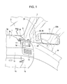
- Figure 1 is a perspective view showing the vicinity surrounding a dashboard assembly 1 on a side of a front passenger's seat in an automobile in accordance with embodiments of the present disclosure. While it is assumed that, in the automobile disclosed, a driver's seat is provided on the left side, it should be understood that the driver's and passenger's positions may be reversed (i.e., in a right-hand-drive vehicle) without departing from the scope of the claimed invention.
- dashboard 1 may include a curved top surface 1 a that slopes downward as it extends toward the rear of the vehicle from a lower edge 3a of a front windshield 3.
- a container holder 5 may be provided as an accommodation unit at a door-side (i.e., longitudinal) end 1 b of dashboard 1 situated at an outer side of a curved top surface 1 a. That is, in the vicinity of a door opening 7 at the longitudinal end 1 b of dashboard 1, container holder 5 may be provided as an accommodation unit.
- container holder 5 i.e., a cup or beverage holder
- accommodation units configured to retain cups, bottles, cans, loose change, sunglasses, ashtrays, and various other objects may be substituted for container holder 5 depicted.
- a side mirror 11 may be mounted to a location near container holder 5 upon a door 9 that opens and closes the door opening 7.
- mirror 11 may be positioned adjacent to a door window 21 provided by door 9.
- Dashboard 1 may also include a front face 1c extending downward from curved top surface 1 a.
- An HVAC vent opening 13 may be provided at an end portion of front face 1c and below container holder 5.
- a glove box 15 may be provided in a lower inclined surface 1d of dashboard 1. As shown, inclined surface 1d may be continuously formed with front face 1c of dashboard 1 so as to incline further downward from front face 1 c and towards the front side of the vehicle.
- a pathway for heated and/or cooled air in dashboard 1 for connecting an HVAC system to vent opening 13 may be constructed to divert airflow toward an interior of container holder 5.
- the pathway may cause a portion of heated and/or cooled air from the HVAC system to flow into the container holder 5 to heat or cool a beverage container 17 contained therein.
- a defrosting side vent 19 may be provided in curved top surface of dashboard 1 and may be disposed between container holder 5 and lower edge 3a of front windshield 3. Air blown from the defrosting vent 19 may be blown in the vicinity of a lower corner of door window 21 to prevent fogging of door window 21.
- FIG. 2A depicts a lid 23 of container holder 5 in an open position.
- lid 23 stands up on its side adjacent to side mirror 11.
- Figure 2B depicts lid 23 of container holder 5 in a closed position.
- Figure 3 depicts an exploded perspective view of container holder 5.
- container holder 5 includes a main body 25, lid 23, and a trim piece 27.
- Lid 23 may be pivotally mounted to main body 25 so that it can be opened and closed.
- Trim piece 27 may be secured to a top portion of main body 25 so as to cover the periphery of lid 23 when in the closed position.
- the colors of trim piece 27 and an outer portion 35 (described below) of lid 23 of the lid 23, which are exposed may be the same or similar color as the remainder of dashboard 1.
- Main body 25 may comprise a container supporting unit 29 and a lid supporting unit 31.
- Container supporting unit 29 may have a recessed portion 29a to accommodate a beverage container 17 ( Figure 1 ).
- Lid supporting unit 31 may be integrally provided with container supporting unit 29 so as to cover an opening in a vehicle-width direction outer side of container supporting unit 29.
- container supporting unit 29 includes a bottom wall 29b, a side wall 29c, a front wall 29d, and a back wall 29e.
- Bottom wall 29b may define the aforementioned recessed portion 29a.
- Side wall 29c may be positioned at an inner side in the vehicle-width direction.
- Lid supporting unit 31 may include supporting protrusions 33 positioned on top portions of front wall 29d and back wall 29e.
- Lid 23 may comprise a lid outer portion 35 and a lid inner portion 39.
- Lid inner portion 39 may be secured to a back face of lid outer portion 35 by screws 37.
- Lid inner portion 39 may include pair of rotating supporting units 41 of lid inner portion 39 that protrude inward (in the vehicle width direction) from respective longitudinal-direction ends when lid outer portion 35 is closed. Rotating supporting units 41 may be inserted into respective gaps 43.
- One of gaps 43 may be formed between front wall 29d of container supporting unit 29 and corresponding supporting protrusion 33 of lid supporting unit 31.
- the other gap 43 may be formed between back wall 29e of container supporting unit 29 and corresponding supporting protrusion 33 of lid supporting unit 31.
- Bushing collars 45 may be inserted through holes 41 a of rotating supporting units 41. Axial lengths of collars 45 may be substantially the same as gaps 43 and may be slightly longer than the width of rotating supporting units 41. Thus, fasteners 47 (e.g. screws, rivets, bolts, etc) may be inserted through holes 33a of supporting protrusions 33 and collars 45 and into a screw holes 29d1 and 29e1 of front and back walls 29d and 29e.
- fasteners 47 e.g. screws, rivets, bolts, etc
- lid inner portion 29, including rotating supporting units 41 may be rotated around rotating supporting units 41 with respect to main body 25 between open ( Figure 2A ) and closed ( Figure 2B ) positions.
- trim piece 27 may include an opening 27a into which lid outer portion 35 in the closed state of Figure 2B moves.
- Trim piece 27 may be secured to main body 25 by fitting engaging pins 49 of main body 25 into trim piece 27.
- Engaging pins 49 may be provided to and protrude upward from a top end surface of main body 25 such that two engaging pins 49 may be provided at container supporting unit 29 one engaging pin 49 may be provided at lid supporting unit 31.
- container holder 5 may be secured to dashboard 1 by fitting it to end portion 1b provided at the lower side of the curved top surface 1 a of the dashboard 1 as shown in Figure 1 . Furthermore, protrusions (not shown) of container holder 5may be engaged into corresponding holes (not shown) of dashboard 1. Such engaging protrusions may be formed at a lower surface of the vehicle front side of trim piece 27 and may protrude in a downward direction.
- Figure 4A is a side sectional view of dashboard 1 taken along line IVA-IVA of Figure 1 .
- Figure 4B is a plan view of container holder 5 (and vicinity) of Figure 1 viewed from outside of the vehicle.
- Figures 4A and 4B both depict lid 23 in the open state.
- outer portion 35 of opened lid 23 may be offset from an area B (indicating a direction in which air is blown out from defrosting side vent 19) so as to not obstruct the flow of air flowing from defrosting side vent 19 to door window 21.
- outer portion 35 of lid 23 may be formed so that a portion 35a situated adjacent to area B extends offset and in the same direction as the an axis (i.e., a central axis) P of the airflow from defrosting side vent 19.
- the direction in which the air is blown out from the defrosting side vent 19 may be determined by a louver provided at the defrosting side vent 19.
- beverage container 17 may be contained in recessed portion 29a of container supporting unit 29 of main body 25 following the opening of lid 23 of container holder 5.
- beverage container 17 may be cooled or heated by directed heated and/or cooled airflow in recessed portion 29a through the pathway for the heated and/or cooled air in the dashboard 1 described above for diverting airflow toward an interior of container holder 5.
- lid 23 When container holder 5 is not used (i.e., when no beverage container 17 is present), lid 23 may be closed as shown in Figure 2B to leave a visually appealing appearance. Additionally, leakage of air from recessed portion 29a of the heated and/or cooled air flowing therethrough is restricted. Thus, it may be possible to reduce the amount of heated and/or cooled air that is diverted from vent opening 13.
- container holder 5 were constructed without lid 23, a driver seated to the left of passenger's seat viewing side mirror 11, a portion of the beverage container 17 positioned in container holder 5 adjacent to side mirror 11 would be reflected in door window 21. As such, the portion of beverage container 17 reflected in door window and side mirror 11 might possibly overlap or obstruct a line of sight of the driver. Therefore, the portion of beverage container 17 reflected in door window 21 may be at a position where it is reflected in side mirror 11.
- lid 23 (including outer portion 35) is positioned between side mirror 11 and beverage container 17 when in the open state. Therefore, a portion of lid 23 having a color similar to that of surrounding portions of dashboard 1 will be reflected (as an image 23A) in door window 21 and side mirror 11 to overlap the line of sight of the driver instead. That is, open lid 23 whose color is similar to that of dashboard 1 will be reflected in side mirror 11 as image 23A hiding beverage container 17. Accordingly, it is possible to prevent beverage container 17 from being reflected in side mirror 11. Therefore, it is possible to prevent a driver from being distracted by a beverage container (or any other object) reflected in side mirror 11, so that the driver may safely check his rearward field of view.
- lid 23 reflected in side mirror 11 as image 23A may be similar to or the same as that of dashboard 1, it may be less of a distraction to the driver if reflected in side mirror 11 than a beverage container 17 would be.
- vehicle rear-end side of open lid 23 protrudes in a rearward direction of the vehicle with respect to recessed portion 29a. Therefore, even if the portion of beverage container 17 reflected in door window 21 and side mirror 11 overlaps a line of sight of the driver, the portion of beverage container 17 reflected in door window 21, it is possible to reliably prevent the beverage container 17 from being reflected in the side mirror 11.
- defrosting side vent 19 that blows out air towards door window 21 at door 9 may be provided in dashboard 1, and because open lid 23 of container holder 5 may be displaced from the area situated towards the front in the direction in which air is blown out from defrosting vent 19, the air blown out from defrosting side vent 19 may be blocked by open lid 23. Therefore, a desired de-fogging function may be ensured for door window 21.
- a straight-line portion (e.g., 35a of Figure 2A ) extending in the same direction as the airflow blowout direction may be provided at lid 23, it is possible to more effectively prevent lid 23 from blocking the air blown out from defrosting side vent 19 along area B.
Landscapes
- Engineering & Computer Science (AREA)
- Physics & Mathematics (AREA)
- Thermal Sciences (AREA)
- Mechanical Engineering (AREA)
- Transportation (AREA)
- Passenger Equipment (AREA)
- Vehicle Step Arrangements And Article Storage (AREA)
- Rear-View Mirror Devices That Are Mounted On The Exterior Of The Vehicle (AREA)
Applications Claiming Priority (2)
| Application Number | Priority Date | Filing Date | Title |
|---|---|---|---|
| JP2007142487 | 2007-05-29 | ||
| JP2008011740A JP4968084B2 (ja) | 2007-05-29 | 2008-01-22 | インストルメントパネルの収納物収納構造 |
Publications (3)
| Publication Number | Publication Date |
|---|---|
| EP1997677A2 true EP1997677A2 (de) | 2008-12-03 |
| EP1997677A3 EP1997677A3 (de) | 2010-12-01 |
| EP1997677B1 EP1997677B1 (de) | 2013-09-11 |
Family
ID=39685218
Family Applications (1)
| Application Number | Title | Priority Date | Filing Date |
|---|---|---|---|
| EP08157107.7A Ceased EP1997677B1 (de) | 2007-05-29 | 2008-05-28 | Staufachstruktur in einem Fahrzeugarmaturenbrett |
Country Status (2)
| Country | Link |
|---|---|
| US (1) | US7780212B2 (de) |
| EP (1) | EP1997677B1 (de) |
Families Citing this family (7)
| Publication number | Priority date | Publication date | Assignee | Title |
|---|---|---|---|---|
| US20120193070A1 (en) * | 2011-02-01 | 2012-08-02 | Adrian Ryan Lynn | Drinkware conditioner |
| USD654010S1 (en) | 2011-03-23 | 2012-02-14 | Robert Maks | Air circulation cup holder |
| US9090208B2 (en) | 2013-06-05 | 2015-07-28 | Ford Global Technologies, Llc | End cap door assembly |
| US9862296B2 (en) * | 2015-02-13 | 2018-01-09 | Ford Global Technologies, Llc | Cup holder system for a motor vehicle |
| TWM505421U (zh) | 2015-04-01 | 2015-07-21 | Cheng-Shung Wang | 簡易車內冷暖箱設計裝置組合 |
| US11872922B1 (en) * | 2022-09-15 | 2024-01-16 | Honda Motor Co., Ltd. | Beverage container holder assembly for vehicle |
| US12434613B2 (en) | 2023-09-28 | 2025-10-07 | Toyota Motor Engineering & Manufacturing North America, Inc. | Apparatus, system, and method for vehicle cup holder with integrated grate and drip tray |
Citations (3)
| Publication number | Priority date | Publication date | Assignee | Title |
|---|---|---|---|---|
| JP2000135935A (ja) | 1998-10-30 | 2000-05-16 | Inoac Corp | インストルメントパネルの容器ホルダ |
| JP2007142487A (ja) | 2005-11-14 | 2007-06-07 | Sony Corp | サンプリング周波数変換装置及び信号切換え装置 |
| JP2008011740A (ja) | 2006-07-04 | 2008-01-24 | Maruyama Mfg Co Ltd | 刈払機 |
Family Cites Families (13)
| Publication number | Priority date | Publication date | Assignee | Title |
|---|---|---|---|---|
| US4892138A (en) * | 1989-01-30 | 1990-01-09 | Bibik Jr Frank F | Beverage temperature controlling assembly for a vehicle |
| US5165646A (en) * | 1991-10-07 | 1992-11-24 | Gewecke Danny F | Auto dashboard drink conditioner |
| US5203833A (en) * | 1992-03-16 | 1993-04-20 | Howell David S | Food storage container heated and cooled by conditioned air in a motor vehicle |
| US5701754A (en) * | 1995-09-29 | 1997-12-30 | Choi; Young Tai | Automobile refrigerator |
| DE19711832C1 (de) * | 1997-03-21 | 1998-10-22 | Happich Gmbh Gebr | Behälter in einem Kraftfahrzeug zum Aufbewahren von Getränken und/oder Lebensmitteln |
| US6155063A (en) * | 1999-07-29 | 2000-12-05 | Felde; Philip E. | Beverage temperature control system for a vehicle |
| DE10007594A1 (de) * | 2000-02-18 | 2001-08-23 | Fischer Artur Werke Gmbh | Halterung für einen Getränkebehälter |
| US6533232B1 (en) * | 2000-05-04 | 2003-03-18 | Konrad Aggeler | Holder and sleeve for a beverage |
| JP4173646B2 (ja) * | 2001-03-16 | 2008-10-29 | カルソニックカンセイ株式会社 | 車両用空調装置 |
| US7073338B2 (en) * | 2003-12-03 | 2006-07-11 | Lear Corporation | Thermally controlled storage space system for an interior cabin of a vehicle |
| JP2005313749A (ja) * | 2004-04-28 | 2005-11-10 | Kawasaki Heavy Ind Ltd | ドリンクホルダー |
| JP4519565B2 (ja) * | 2004-08-05 | 2010-08-04 | 株式会社ニフコ | 小物入れ |
| US7389650B2 (en) * | 2005-11-04 | 2008-06-24 | Chrysler Llc | Cooled instrument panel compartment for a vehicle |
-
2008
- 2008-04-08 US US12/099,487 patent/US7780212B2/en active Active
- 2008-05-28 EP EP08157107.7A patent/EP1997677B1/de not_active Ceased
Patent Citations (3)
| Publication number | Priority date | Publication date | Assignee | Title |
|---|---|---|---|---|
| JP2000135935A (ja) | 1998-10-30 | 2000-05-16 | Inoac Corp | インストルメントパネルの容器ホルダ |
| JP2007142487A (ja) | 2005-11-14 | 2007-06-07 | Sony Corp | サンプリング周波数変換装置及び信号切換え装置 |
| JP2008011740A (ja) | 2006-07-04 | 2008-01-24 | Maruyama Mfg Co Ltd | 刈払機 |
Also Published As
| Publication number | Publication date |
|---|---|
| US20080296923A1 (en) | 2008-12-04 |
| EP1997677B1 (de) | 2013-09-11 |
| EP1997677A3 (de) | 2010-12-01 |
| US7780212B2 (en) | 2010-08-24 |
Similar Documents
| Publication | Publication Date | Title |
|---|---|---|
| EP1997677B1 (de) | Staufachstruktur in einem Fahrzeugarmaturenbrett | |
| CN212148406U (zh) | 车辆 | |
| US7494170B2 (en) | Vehicle instrument panel having movable storage compartment | |
| CN101346257B (zh) | 用于安装到汽车内的设备支架 | |
| US6267428B1 (en) | Overhead console for motor vehicle | |
| CN102686448B (zh) | 具有自动饮品保持装置的托盘机构 | |
| US6070927A (en) | Container in a motor vehicle for storing drinks and/or food | |
| EP1782998A2 (de) | Gekühltes Instrumenttafelsfach für Fahrzeug | |
| CN109774425B (zh) | 车辆部件 | |
| US6866318B1 (en) | Beverage container holder for vehicles | |
| CN101318474B (zh) | 汽车仪表板的结构、汽车仪表板及其容纳单元、及在汽车仪表板中保持物件的方法 | |
| JP4982521B2 (ja) | 車両用カップホルダー構造 | |
| JP2000043632A (ja) | カップホルダー付きベント | |
| JP4162778B2 (ja) | インストルメントパネルの容器ホルダ | |
| CN101065268A (zh) | 用于汽车的手套箱 | |
| JP3490181B2 (ja) | 自動車のカップホルダ | |
| EP1410946A1 (de) | Becherhalter | |
| US10118570B2 (en) | Shift console for a motor vehicle | |
| JP4851136B2 (ja) | 車両用カップホルダ装置 | |
| KR100523576B1 (ko) | 글로브박스의 스트라이커 장착 구조 | |
| KR950007130Y1 (ko) | 자동차의 냉장글로브박스 | |
| US20060150654A1 (en) | Cup holder | |
| WO2019049850A1 (ja) | ベンチレーショングリル | |
| JPH07172153A (ja) | 自動車の小物入れボックス構造 | |
| JPH07172241A (ja) | 自動車の小物入れボックス構造 |
Legal Events
| Date | Code | Title | Description |
|---|---|---|---|
| PUAI | Public reference made under article 153(3) epc to a published international application that has entered the european phase |
Free format text: ORIGINAL CODE: 0009012 |
|
| AK | Designated contracting states |
Kind code of ref document: A2 Designated state(s): AT BE BG CH CY CZ DE DK EE ES FI FR GB GR HR HU IE IS IT LI LT LU LV MC MT NL NO PL PT RO SE SI SK TR |
|
| AX | Request for extension of the european patent |
Extension state: AL BA MK RS |
|
| RIN1 | Information on inventor provided before grant (corrected) |
Inventor name: HIRATA, HIDEKI Inventor name: NOGUCHI, KAZUHIKO |
|
| PUAL | Search report despatched |
Free format text: ORIGINAL CODE: 0009013 |
|
| AK | Designated contracting states |
Kind code of ref document: A3 Designated state(s): AT BE BG CH CY CZ DE DK EE ES FI FR GB GR HR HU IE IS IT LI LT LU LV MC MT NL NO PL PT RO SE SI SK TR |
|
| AX | Request for extension of the european patent |
Extension state: AL BA MK RS |
|
| 17P | Request for examination filed |
Effective date: 20110601 |
|
| AKX | Designation fees paid |
Designated state(s): DE FR GB |
|
| 17Q | First examination report despatched |
Effective date: 20121129 |
|
| GRAP | Despatch of communication of intention to grant a patent |
Free format text: ORIGINAL CODE: EPIDOSNIGR1 |
|
| INTG | Intention to grant announced |
Effective date: 20130613 |
|
| GRAS | Grant fee paid |
Free format text: ORIGINAL CODE: EPIDOSNIGR3 |
|
| GRAA | (expected) grant |
Free format text: ORIGINAL CODE: 0009210 |
|
| AK | Designated contracting states |
Kind code of ref document: B1 Designated state(s): DE FR GB |
|
| REG | Reference to a national code |
Ref country code: GB Ref legal event code: FG4D |
|
| REG | Reference to a national code |
Ref country code: DE Ref legal event code: R096 Ref document number: 602008027433 Country of ref document: DE Effective date: 20131107 |
|
| REG | Reference to a national code |
Ref country code: DE Ref legal event code: R097 Ref document number: 602008027433 Country of ref document: DE |
|
| PLBE | No opposition filed within time limit |
Free format text: ORIGINAL CODE: 0009261 |
|
| STAA | Information on the status of an ep patent application or granted ep patent |
Free format text: STATUS: NO OPPOSITION FILED WITHIN TIME LIMIT |
|
| 26N | No opposition filed |
Effective date: 20140612 |
|
| REG | Reference to a national code |
Ref country code: DE Ref legal event code: R097 Ref document number: 602008027433 Country of ref document: DE Effective date: 20140612 |
|
| REG | Reference to a national code |
Ref country code: FR Ref legal event code: PLFP Year of fee payment: 9 |
|
| REG | Reference to a national code |
Ref country code: FR Ref legal event code: PLFP Year of fee payment: 10 |
|
| REG | Reference to a national code |
Ref country code: FR Ref legal event code: PLFP Year of fee payment: 11 |
|
| PGFP | Annual fee paid to national office [announced via postgrant information from national office to epo] |
Ref country code: GB Payment date: 20180329 Year of fee payment: 11 |
|
| PGFP | Annual fee paid to national office [announced via postgrant information from national office to epo] |
Ref country code: DE Payment date: 20180515 Year of fee payment: 11 |
|
| PGFP | Annual fee paid to national office [announced via postgrant information from national office to epo] |
Ref country code: FR Payment date: 20180411 Year of fee payment: 11 |
|
| REG | Reference to a national code |
Ref country code: DE Ref legal event code: R119 Ref document number: 602008027433 Country of ref document: DE |
|
| GBPC | Gb: european patent ceased through non-payment of renewal fee |
Effective date: 20190528 |
|
| PG25 | Lapsed in a contracting state [announced via postgrant information from national office to epo] |
Ref country code: DE Free format text: LAPSE BECAUSE OF NON-PAYMENT OF DUE FEES Effective date: 20191203 Ref country code: GB Free format text: LAPSE BECAUSE OF NON-PAYMENT OF DUE FEES Effective date: 20190528 |
|
| PG25 | Lapsed in a contracting state [announced via postgrant information from national office to epo] |
Ref country code: FR Free format text: LAPSE BECAUSE OF NON-PAYMENT OF DUE FEES Effective date: 20190531 |