EP1995211B1 - Hydrogen generator - Google Patents
Hydrogen generator Download PDFInfo
- Publication number
- EP1995211B1 EP1995211B1 EP07706404.6A EP07706404A EP1995211B1 EP 1995211 B1 EP1995211 B1 EP 1995211B1 EP 07706404 A EP07706404 A EP 07706404A EP 1995211 B1 EP1995211 B1 EP 1995211B1
- Authority
- EP
- European Patent Office
- Prior art keywords
- dehydrogenation
- hydrogen
- catalyst
- reactor vessel
- fuel
- Prior art date
- Legal status (The legal status is an assumption and is not a legal conclusion. Google has not performed a legal analysis and makes no representation as to the accuracy of the status listed.)
- Active
Links
Images
Classifications
-
- F—MECHANICAL ENGINEERING; LIGHTING; HEATING; WEAPONS; BLASTING
- F17—STORING OR DISTRIBUTING GASES OR LIQUIDS
- F17C—VESSELS FOR CONTAINING OR STORING COMPRESSED, LIQUEFIED OR SOLIDIFIED GASES; FIXED-CAPACITY GAS-HOLDERS; FILLING VESSELS WITH, OR DISCHARGING FROM VESSELS, COMPRESSED, LIQUEFIED, OR SOLIDIFIED GASES
- F17C11/00—Use of gas-solvents or gas-sorbents in vessels
- F17C11/005—Use of gas-solvents or gas-sorbents in vessels for hydrogen
-
- B—PERFORMING OPERATIONS; TRANSPORTING
- B01—PHYSICAL OR CHEMICAL PROCESSES OR APPARATUS IN GENERAL
- B01J—CHEMICAL OR PHYSICAL PROCESSES, e.g. CATALYSIS OR COLLOID CHEMISTRY; THEIR RELEVANT APPARATUS
- B01J12/00—Chemical processes in general for reacting gaseous media with gaseous media; Apparatus specially adapted therefor
- B01J12/007—Chemical processes in general for reacting gaseous media with gaseous media; Apparatus specially adapted therefor in the presence of catalytically active bodies, e.g. porous plates
-
- B—PERFORMING OPERATIONS; TRANSPORTING
- B01—PHYSICAL OR CHEMICAL PROCESSES OR APPARATUS IN GENERAL
- B01J—CHEMICAL OR PHYSICAL PROCESSES, e.g. CATALYSIS OR COLLOID CHEMISTRY; THEIR RELEVANT APPARATUS
- B01J15/00—Chemical processes in general for reacting gaseous media with non-particulate solids, e.g. sheet material; Apparatus specially adapted therefor
- B01J15/005—Chemical processes in general for reacting gaseous media with non-particulate solids, e.g. sheet material; Apparatus specially adapted therefor in the presence of catalytically active bodies, e.g. porous plates
-
- B—PERFORMING OPERATIONS; TRANSPORTING
- B01—PHYSICAL OR CHEMICAL PROCESSES OR APPARATUS IN GENERAL
- B01J—CHEMICAL OR PHYSICAL PROCESSES, e.g. CATALYSIS OR COLLOID CHEMISTRY; THEIR RELEVANT APPARATUS
- B01J21/00—Catalysts comprising the elements, oxides, or hydroxides of magnesium, boron, aluminium, carbon, silicon, titanium, zirconium, or hafnium
- B01J21/02—Boron or aluminium; Oxides or hydroxides thereof
- B01J21/04—Alumina
-
- B—PERFORMING OPERATIONS; TRANSPORTING
- B01—PHYSICAL OR CHEMICAL PROCESSES OR APPARATUS IN GENERAL
- B01J—CHEMICAL OR PHYSICAL PROCESSES, e.g. CATALYSIS OR COLLOID CHEMISTRY; THEIR RELEVANT APPARATUS
- B01J23/00—Catalysts comprising metals or metal oxides or hydroxides, not provided for in group B01J21/00
- B01J23/38—Catalysts comprising metals or metal oxides or hydroxides, not provided for in group B01J21/00 of noble metals
- B01J23/40—Catalysts comprising metals or metal oxides or hydroxides, not provided for in group B01J21/00 of noble metals of the platinum group metals
- B01J23/42—Platinum
-
- B—PERFORMING OPERATIONS; TRANSPORTING
- B01—PHYSICAL OR CHEMICAL PROCESSES OR APPARATUS IN GENERAL
- B01J—CHEMICAL OR PHYSICAL PROCESSES, e.g. CATALYSIS OR COLLOID CHEMISTRY; THEIR RELEVANT APPARATUS
- B01J37/00—Processes, in general, for preparing catalysts; Processes, in general, for activation of catalysts
- B01J37/34—Irradiation by, or application of, electric, magnetic or wave energy, e.g. ultrasonic waves ; Ionic sputtering; Flame or plasma spraying; Particle radiation
- B01J37/348—Electrochemical processes, e.g. electrochemical deposition or anodisation
-
- B—PERFORMING OPERATIONS; TRANSPORTING
- B01—PHYSICAL OR CHEMICAL PROCESSES OR APPARATUS IN GENERAL
- B01J—CHEMICAL OR PHYSICAL PROCESSES, e.g. CATALYSIS OR COLLOID CHEMISTRY; THEIR RELEVANT APPARATUS
- B01J8/00—Chemical or physical processes in general, conducted in the presence of fluids and solid particles; Apparatus for such processes
- B01J8/02—Chemical or physical processes in general, conducted in the presence of fluids and solid particles; Apparatus for such processes with stationary particles, e.g. in fixed beds
- B01J8/04—Chemical or physical processes in general, conducted in the presence of fluids and solid particles; Apparatus for such processes with stationary particles, e.g. in fixed beds the fluid passing successively through two or more beds
- B01J8/0403—Chemical or physical processes in general, conducted in the presence of fluids and solid particles; Apparatus for such processes with stationary particles, e.g. in fixed beds the fluid passing successively through two or more beds the fluid flow within the beds being predominantly horizontal
- B01J8/0407—Chemical or physical processes in general, conducted in the presence of fluids and solid particles; Apparatus for such processes with stationary particles, e.g. in fixed beds the fluid passing successively through two or more beds the fluid flow within the beds being predominantly horizontal through two or more cylindrical annular shaped beds
- B01J8/0411—Chemical or physical processes in general, conducted in the presence of fluids and solid particles; Apparatus for such processes with stationary particles, e.g. in fixed beds the fluid passing successively through two or more beds the fluid flow within the beds being predominantly horizontal through two or more cylindrical annular shaped beds the beds being concentric
-
- B—PERFORMING OPERATIONS; TRANSPORTING
- B01—PHYSICAL OR CHEMICAL PROCESSES OR APPARATUS IN GENERAL
- B01J—CHEMICAL OR PHYSICAL PROCESSES, e.g. CATALYSIS OR COLLOID CHEMISTRY; THEIR RELEVANT APPARATUS
- B01J8/00—Chemical or physical processes in general, conducted in the presence of fluids and solid particles; Apparatus for such processes
- B01J8/02—Chemical or physical processes in general, conducted in the presence of fluids and solid particles; Apparatus for such processes with stationary particles, e.g. in fixed beds
- B01J8/04—Chemical or physical processes in general, conducted in the presence of fluids and solid particles; Apparatus for such processes with stationary particles, e.g. in fixed beds the fluid passing successively through two or more beds
- B01J8/0496—Heating or cooling the reactor
-
- C—CHEMISTRY; METALLURGY
- C01—INORGANIC CHEMISTRY
- C01B—NON-METALLIC ELEMENTS; COMPOUNDS THEREOF; METALLOIDS OR COMPOUNDS THEREOF NOT COVERED BY SUBCLASS C01C
- C01B3/00—Hydrogen; Gaseous mixtures containing hydrogen; Separation of hydrogen from mixtures containing it; Purification of hydrogen
- C01B3/02—Production of hydrogen or of gaseous mixtures containing a substantial proportion of hydrogen
- C01B3/22—Production of hydrogen or of gaseous mixtures containing a substantial proportion of hydrogen by decomposition of gaseous or liquid organic compounds
- C01B3/24—Production of hydrogen or of gaseous mixtures containing a substantial proportion of hydrogen by decomposition of gaseous or liquid organic compounds of hydrocarbons
- C01B3/26—Production of hydrogen or of gaseous mixtures containing a substantial proportion of hydrogen by decomposition of gaseous or liquid organic compounds of hydrocarbons using catalysts
-
- B—PERFORMING OPERATIONS; TRANSPORTING
- B01—PHYSICAL OR CHEMICAL PROCESSES OR APPARATUS IN GENERAL
- B01J—CHEMICAL OR PHYSICAL PROCESSES, e.g. CATALYSIS OR COLLOID CHEMISTRY; THEIR RELEVANT APPARATUS
- B01J2208/00—Processes carried out in the presence of solid particles; Reactors therefor
- B01J2208/00008—Controlling the process
- B01J2208/00017—Controlling the temperature
- B01J2208/00106—Controlling the temperature by indirect heat exchange
- B01J2208/00115—Controlling the temperature by indirect heat exchange with heat exchange elements inside the bed of solid particles
- B01J2208/00123—Fingers
-
- B—PERFORMING OPERATIONS; TRANSPORTING
- B01—PHYSICAL OR CHEMICAL PROCESSES OR APPARATUS IN GENERAL
- B01J—CHEMICAL OR PHYSICAL PROCESSES, e.g. CATALYSIS OR COLLOID CHEMISTRY; THEIR RELEVANT APPARATUS
- B01J2208/00—Processes carried out in the presence of solid particles; Reactors therefor
- B01J2208/00008—Controlling the process
- B01J2208/00017—Controlling the temperature
- B01J2208/00106—Controlling the temperature by indirect heat exchange
- B01J2208/00309—Controlling the temperature by indirect heat exchange with two or more reactions in heat exchange with each other, such as an endothermic reaction in heat exchange with an exothermic reaction
-
- B—PERFORMING OPERATIONS; TRANSPORTING
- B01—PHYSICAL OR CHEMICAL PROCESSES OR APPARATUS IN GENERAL
- B01J—CHEMICAL OR PHYSICAL PROCESSES, e.g. CATALYSIS OR COLLOID CHEMISTRY; THEIR RELEVANT APPARATUS
- B01J2208/00—Processes carried out in the presence of solid particles; Reactors therefor
- B01J2208/00008—Controlling the process
- B01J2208/00017—Controlling the temperature
- B01J2208/00504—Controlling the temperature by means of a burner
-
- B—PERFORMING OPERATIONS; TRANSPORTING
- B01—PHYSICAL OR CHEMICAL PROCESSES OR APPARATUS IN GENERAL
- B01J—CHEMICAL OR PHYSICAL PROCESSES, e.g. CATALYSIS OR COLLOID CHEMISTRY; THEIR RELEVANT APPARATUS
- B01J2208/00—Processes carried out in the presence of solid particles; Reactors therefor
- B01J2208/00008—Controlling the process
- B01J2208/00017—Controlling the temperature
- B01J2208/0053—Controlling multiple zones along the direction of flow, e.g. pre-heating and after-cooling
-
- B—PERFORMING OPERATIONS; TRANSPORTING
- B01—PHYSICAL OR CHEMICAL PROCESSES OR APPARATUS IN GENERAL
- B01J—CHEMICAL OR PHYSICAL PROCESSES, e.g. CATALYSIS OR COLLOID CHEMISTRY; THEIR RELEVANT APPARATUS
- B01J2219/00—Chemical, physical or physico-chemical processes in general; Their relevant apparatus
- B01J2219/00049—Controlling or regulating processes
- B01J2219/00051—Controlling the temperature
- B01J2219/00074—Controlling the temperature by indirect heating or cooling employing heat exchange fluids
- B01J2219/00076—Controlling the temperature by indirect heating or cooling employing heat exchange fluids with heat exchange elements inside the reactor
- B01J2219/00078—Fingers
-
- B—PERFORMING OPERATIONS; TRANSPORTING
- B01—PHYSICAL OR CHEMICAL PROCESSES OR APPARATUS IN GENERAL
- B01J—CHEMICAL OR PHYSICAL PROCESSES, e.g. CATALYSIS OR COLLOID CHEMISTRY; THEIR RELEVANT APPARATUS
- B01J2219/00—Chemical, physical or physico-chemical processes in general; Their relevant apparatus
- B01J2219/00049—Controlling or regulating processes
- B01J2219/00051—Controlling the temperature
- B01J2219/00074—Controlling the temperature by indirect heating or cooling employing heat exchange fluids
- B01J2219/00117—Controlling the temperature by indirect heating or cooling employing heat exchange fluids with two or more reactions in heat exchange with each other, such as an endothermic reaction in heat exchange with an exothermic reaction
-
- B—PERFORMING OPERATIONS; TRANSPORTING
- B01—PHYSICAL OR CHEMICAL PROCESSES OR APPARATUS IN GENERAL
- B01J—CHEMICAL OR PHYSICAL PROCESSES, e.g. CATALYSIS OR COLLOID CHEMISTRY; THEIR RELEVANT APPARATUS
- B01J2219/00—Chemical, physical or physico-chemical processes in general; Their relevant apparatus
- B01J2219/00049—Controlling or regulating processes
- B01J2219/00051—Controlling the temperature
- B01J2219/00157—Controlling the temperature by means of a burner
-
- B—PERFORMING OPERATIONS; TRANSPORTING
- B01—PHYSICAL OR CHEMICAL PROCESSES OR APPARATUS IN GENERAL
- B01J—CHEMICAL OR PHYSICAL PROCESSES, e.g. CATALYSIS OR COLLOID CHEMISTRY; THEIR RELEVANT APPARATUS
- B01J2219/00—Chemical, physical or physico-chemical processes in general; Their relevant apparatus
- B01J2219/00049—Controlling or regulating processes
- B01J2219/00051—Controlling the temperature
- B01J2219/00159—Controlling the temperature controlling multiple zones along the direction of flow, e.g. pre-heating and after-cooling
-
- B—PERFORMING OPERATIONS; TRANSPORTING
- B01—PHYSICAL OR CHEMICAL PROCESSES OR APPARATUS IN GENERAL
- B01J—CHEMICAL OR PHYSICAL PROCESSES, e.g. CATALYSIS OR COLLOID CHEMISTRY; THEIR RELEVANT APPARATUS
- B01J2219/00—Chemical, physical or physico-chemical processes in general; Their relevant apparatus
- B01J2219/00761—Details of the reactor
- B01J2219/00763—Baffles
- B01J2219/00765—Baffles attached to the reactor wall
- B01J2219/00768—Baffles attached to the reactor wall vertical
-
- B—PERFORMING OPERATIONS; TRANSPORTING
- B01—PHYSICAL OR CHEMICAL PROCESSES OR APPARATUS IN GENERAL
- B01J—CHEMICAL OR PHYSICAL PROCESSES, e.g. CATALYSIS OR COLLOID CHEMISTRY; THEIR RELEVANT APPARATUS
- B01J35/00—Catalysts, in general, characterised by their form or physical properties
- B01J35/50—Catalysts, in general, characterised by their form or physical properties characterised by their shape or configuration
- B01J35/56—Foraminous structures having flow-through passages or channels, e.g. grids or three-dimensional monoliths
-
- C—CHEMISTRY; METALLURGY
- C01—INORGANIC CHEMISTRY
- C01B—NON-METALLIC ELEMENTS; COMPOUNDS THEREOF; METALLOIDS OR COMPOUNDS THEREOF NOT COVERED BY SUBCLASS C01C
- C01B2203/00—Integrated processes for the production of hydrogen or synthesis gas
- C01B2203/02—Processes for making hydrogen or synthesis gas
- C01B2203/0266—Processes for making hydrogen or synthesis gas containing a decomposition step
- C01B2203/0277—Processes for making hydrogen or synthesis gas containing a decomposition step containing a catalytic decomposition step
-
- C—CHEMISTRY; METALLURGY
- C01—INORGANIC CHEMISTRY
- C01B—NON-METALLIC ELEMENTS; COMPOUNDS THEREOF; METALLOIDS OR COMPOUNDS THEREOF NOT COVERED BY SUBCLASS C01C
- C01B2203/00—Integrated processes for the production of hydrogen or synthesis gas
- C01B2203/08—Methods of heating or cooling
- C01B2203/0805—Methods of heating the process for making hydrogen or synthesis gas
- C01B2203/0811—Methods of heating the process for making hydrogen or synthesis gas by combustion of fuel
- C01B2203/0822—Methods of heating the process for making hydrogen or synthesis gas by combustion of fuel the fuel containing hydrogen
-
- C—CHEMISTRY; METALLURGY
- C01—INORGANIC CHEMISTRY
- C01B—NON-METALLIC ELEMENTS; COMPOUNDS THEREOF; METALLOIDS OR COMPOUNDS THEREOF NOT COVERED BY SUBCLASS C01C
- C01B2203/00—Integrated processes for the production of hydrogen or synthesis gas
- C01B2203/08—Methods of heating or cooling
- C01B2203/0805—Methods of heating the process for making hydrogen or synthesis gas
- C01B2203/0811—Methods of heating the process for making hydrogen or synthesis gas by combustion of fuel
- C01B2203/0827—Methods of heating the process for making hydrogen or synthesis gas by combustion of fuel at least part of the fuel being a recycle stream
-
- C—CHEMISTRY; METALLURGY
- C01—INORGANIC CHEMISTRY
- C01B—NON-METALLIC ELEMENTS; COMPOUNDS THEREOF; METALLOIDS OR COMPOUNDS THEREOF NOT COVERED BY SUBCLASS C01C
- C01B2203/00—Integrated processes for the production of hydrogen or synthesis gas
- C01B2203/10—Catalysts for performing the hydrogen forming reactions
- C01B2203/1005—Arrangement or shape of catalyst
- C01B2203/1023—Catalysts in the form of a monolith or honeycomb
-
- C—CHEMISTRY; METALLURGY
- C01—INORGANIC CHEMISTRY
- C01B—NON-METALLIC ELEMENTS; COMPOUNDS THEREOF; METALLOIDS OR COMPOUNDS THEREOF NOT COVERED BY SUBCLASS C01C
- C01B2203/00—Integrated processes for the production of hydrogen or synthesis gas
- C01B2203/10—Catalysts for performing the hydrogen forming reactions
- C01B2203/1005—Arrangement or shape of catalyst
- C01B2203/1035—Catalyst coated on equipment surfaces, e.g. reactor walls
-
- Y—GENERAL TAGGING OF NEW TECHNOLOGICAL DEVELOPMENTS; GENERAL TAGGING OF CROSS-SECTIONAL TECHNOLOGIES SPANNING OVER SEVERAL SECTIONS OF THE IPC; TECHNICAL SUBJECTS COVERED BY FORMER USPC CROSS-REFERENCE ART COLLECTIONS [XRACs] AND DIGESTS
- Y02—TECHNOLOGIES OR APPLICATIONS FOR MITIGATION OR ADAPTATION AGAINST CLIMATE CHANGE
- Y02E—REDUCTION OF GREENHOUSE GAS [GHG] EMISSIONS, RELATED TO ENERGY GENERATION, TRANSMISSION OR DISTRIBUTION
- Y02E60/00—Enabling technologies; Technologies with a potential or indirect contribution to GHG emissions mitigation
- Y02E60/30—Hydrogen technology
- Y02E60/32—Hydrogen storage
-
- Y—GENERAL TAGGING OF NEW TECHNOLOGICAL DEVELOPMENTS; GENERAL TAGGING OF CROSS-SECTIONAL TECHNOLOGIES SPANNING OVER SEVERAL SECTIONS OF THE IPC; TECHNICAL SUBJECTS COVERED BY FORMER USPC CROSS-REFERENCE ART COLLECTIONS [XRACs] AND DIGESTS
- Y02—TECHNOLOGIES OR APPLICATIONS FOR MITIGATION OR ADAPTATION AGAINST CLIMATE CHANGE
- Y02P—CLIMATE CHANGE MITIGATION TECHNOLOGIES IN THE PRODUCTION OR PROCESSING OF GOODS
- Y02P20/00—Technologies relating to chemical industry
- Y02P20/10—Process efficiency
Definitions
- This invention relates to a hydrogen generator for generating hydrogen by way of dehydrogenation of organic hydrides.
- Hydrogen energy has been attracting attention in recent years from the viewpoint of minimizing the air pollution and the global warming that arise due to consumption of fossil fuel and reducing the risk of radiation exposure due to utilization of atomic energy. Since hydrogen can be generated by electrolysis of water, it can safely be said that hydrogen exists almost inexhaustibly on earth. Also, it is a clean energy source that does not give off any carbon dioxide when combusted. This is a main reason why hydrogen attracts attention.
- Known currently commercially available hydrogen storing methods include a method of putting hydrogen into a high pressure tank and hermetically sealing the tank, a method of storing hydrogen in the inside of hydrogen storage alloys and a method of storing hydrogen as liquid hydrogen.
- benzene and cyclohexane are known as cyclic hydrocarbon compounds having a same number of carbon atoms. While benzene is an unsaturated hydrocarbon compound partially having double bonds for bonding carbon atoms, cyclohexane is a saturated hydrocarbon compound having no double bond for bonding carbon atoms. For this reason, cyclohexane is obtained by adding hydrogen to benzene, whereas benzene is obtained by removing part of the hydrogen atoms of cyclohexane. Similarly, decalin is obtained by hydrogenation of naphthalene, whereas naphthalene is obtained by dehydrogenation of decalin.
- JP 2002-187702 A Patent Document 1
- JP 2004 359494 A discloses a hydrogen generator with a combustion chamber or heater which has a hollow, cylindrical internal structure and is used for heating a catalyst; said catalyst is ring-shaped, encircles the heater and has a rectangular cross-sectional surface.
- a hydrogen generator for generating hydrogen by dehydrogenation of organic hydrides in the presence of a catalyst comprises a reactor vessel of a multi-tubular structure having a region for supplying fuel to generate heat necessary for dehydrogenation, the region containing a combustion catalyst for combusting fuel, and a region containing a dehydrogenation catalyst necessary for dehydrogenation, the regions being arranged radially side by side with a wall separating them.
- Dehydrogenation of organic hydrides is an endothermic reaction that requires heat to be supplied at a high rate and energy can hardly be supplied at rate required for the reaction by an ordinary packing type reaction vessel.
- a hydrogen generator according to the present invention directly transmits the energy generated by combusting fuel to the dehydrogenation catalyst in the region other than the region containing the combustion catalyst to realize a high efficiency of utilization of energy and, additionally, a high hydrogen generation rate.
- a hydrogen generator in a hydrogen generator according to the present invention, at least either the combustion catalyst or the dehydrogenation catalyst is supported on the wall surface in the reactor vessel. With this arrangement, heat is transmitted directly from the combustion catalyst through the wall surface so further raise the hydrogen generation rate.
- the wall surface is that of a fin-shaped, pleated, lattice-shaped or honeycomb-shaped member.
- the wall surface supporting the catalyst shows an increased surface area per unit volume to further raise the hydrogen generation rate.
- a hydrogen generator in a hydrogen generator according to the present invention, at least either the combustion catalyst or the dehydrogenation catalyst is supported by an aluminum compound by way of an anodic oxidation process.
- the catalyst can be supported so as to realize a high thermal conductivity.
- heat can be transmitted quickly to the endothermic region by using aluminum, which is an excellent thermal conductor, for the wall surface or the fins of each of the regions.
- the dehydrogenation product is used as fuel.
- the rate at which fuel is supplied externally can be minimized or nullified so that a self-sufficient hydrogen generation system can be realized by utilizing the reaction product of the source materials.
- a hydrogenation apparatus for storing hydrogen by synthesizing organic hydrides by way of hydrogenation of unsaturated hydrocarbons in the presence of a catalyst, characterized by comprising a reactor vessel of a multi-tubular structure having a region for removing the heat generated by hydrogenation and a region containing a hydrogenation catalyst necessary for hydrogenation, the regions being arranged radially side by side with a wall separating them.
- Hydrogenation of unsaturated hydrocarbons for storing hydrogen is an exothermic reaction that gives off heat at a high rate and, at the same time, an equilibrium reaction so that the rate of reaction falls as the temperature rises.
- a hydrogenation apparatus as described can control the rise of the reaction temperature and improve the efficiency of hydrogenation so that the hydrogenation rate can be remarkably boosted.
- the hydrogenation catalyst is supported on the wall surface in the reactor vessel.
- the heat generated by hydrogenation through the wall surface can be immediately removed to further raise the rate of hydrogenation.
- the wall surface is that of a fin-shaped, pleated, lattice-shaped or honeycomb-shaped member.
- the wall surface supporting the catalyst shows an increased surface area per unit volume to further raise the rate of hydrogenation.
- the hydrogenation catalyst is supported by an aluminum compound by way of an anodic oxidation process.
- the catalyst can be supported so as to realize a high thermal conductivity.
- heat can be transmitted quickly from one of the regions to the other by using aluminum, which is an excellent thermal conductor, for the wall surface or the fins of each of the regions.
- the efficiency of dehydrogenation can be improved and, at the same time, the overall energy efficiency can be raised.
- a hydrogen generator can be realized by utilizing compounds such as organic hydrides part or all of the bonds of which is turned to double bonds or triple bonds to give off hydrogen to the outside.
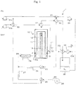
- FIG. 1 is a schematic illustration of a preferable embodiment of hydrogen generator according to the present invention.
- FIG. 1 shows only an embodiment of hydrogen generator according to the present invention and the present invention is by no means limited thereto.
- the hydrogen generator 1 of this embodiment has a reactor vessel 10 that provides a site of dehydrogenation of methylcyclohexane (indicated by "OHY” in FIG. 1 ), which is an organic hydride.
- the reactor vessel 10 shows an oblong cylindrical profile. It is a triple-tubular structure formed by radially arranging three tubes.
- the innermost tube of the reactor vessel 10 is a channel 13 for exhaust gas produced as a mixture of fuel (indicated by "FU” in FIG. 1 ) and air is combusted.
- Fuel that can be used for the purpose of the present invention includes city gas, LPG and kerosene. Both the upstream end and the downstream end of the channel 13 are open to form so many apertures. Exhaust gas flows through the channel 13 from upstream to downstream and is discharged from the reactor vessel 10.
- Another tube having a diameter greater than the channel 13 is arranged radially outside the channel 13.
- the region defined by the tube and the outer wall surface of the channel 13 is a region 12 where a mixture of fuel and air is introduced and combusted (to be referred to as "inner region” in this embodiment).
- the inner region 12 held in communication with a lower part of the lateral wall of the reactor vessel 10 and the upstream end aperture of the channel 13.
- the reactor vessel 10 is provided at the lower part of the lateral wall thereof with one or more than one openings that are held in communication with the inner region 12. While two openings are shown in FIG. 1 , a single opening or three or more than three openings may alternatively be provided.
- Fuel and air enter the inner region 12 through the lower part of the lateral wall of the reactor vessel 10 and consumed for combustion there.
- the exhaust gas produced as a result of the combustion is made to enter the channel 13 from the upstream end thereof and flow to the outside of the reactor vessel 10.
- a tube that also operates as the outer wall of the reactor vessel 10 is arranged outside the inner region 12.
- the region defined by the inner wall of the tube and the outer wall of the tube that defines the inner region is a region 11 where toluene (indicated by "TL” in FIG. 1 ) and hydrogen are generated by dehydrogenation of methylcyclohexane (to be referred to as "outer region” in this embodiment).
- the outer region 11 is held in communication with a lower part of the lateral wall and the top wall of the reactor vessel 10.
- the reactor vessel 10 is provided at the lower part of the lateral wall thereof with one or more than one openings that are held in communication with the outer region 11. While two openings are shown in FIG.
- Methylcyclohexane enters the outer region 11 from the lower part of the lateral wall of the reactor vessel 10 and is dehydrogenated there. Toluene and hydrogen generated by dehydrogenation flow toward the upstream end of the outer region 11 and are discharged to the outside from the top end of the reactor vessel 10.
- the structure of the reactor vessel 10 will be described in greater detail hereinafter.
- the thermal energy necessary for the dehydrogenation in the reactor vessel 10 is obtained by heating fuel and supply it to the combustion catalyst.
- Fuel is fed by a pump 20 a to a flow path changeover valve 21, a heat exchanger 22 and another heat exchanger 23 and subsequently heated by an electric heater 24, which is one of a number of heating means.
- Air to be mixed with fuel (to be referred to simply as “air” hereinafter and indicated by “AR” in FIG. 1 ) is fed to a heat exchanger 26 and heated by an electric heater 27, which is one of a number of heating means, before it is actually mixed with fuel in a mixer 28.
- the mixer 28 is provided with an electric heater 29, which is one of a number of heating means.
- the mixture of fuel and air is sufficiently heated in the mixer 28.
- the mixture of fuel and air that is mixed by the mixer 28 is then introduced into the inner region 12 in the reactor vessel 10 from the plurality of openings (fuel inlet ports) arranged at a lower part of the lateral wall of the reactor vessel 10.
- the electric heaters cited above as heating means are operated mainly at the time of starting the operation of the reactor vessel 10 and thermal energy is self sufficient when the reactor vessel 10 is operating in a steady state so that the electric heaters may not necessarily be operated in a steady state.
- the heat exchanger 22 provides a site where the mixture of toluene and hydrogen generated by dehydrogenation of methylcyclohexane and fuel exchange heat. Fuel is preliminarily heated as it gets heat from the mixture of toluene and hydrogen. The mixture of toluene and hydrogen, on the other hand, is deprived of heat by fuel and cooled.
- the heat exchanger 23 provides a site where exhaust gas produced as the mixture of fuel and air is combusted and fuel exchange heat. Fuel is preliminarily heated as it gets heat from exhaust gas. Exhaust gas, on the other hand, is deprived of heat by fuel and cooled.
- the heat exchanger 26 provides a site where exhaust gas produced as the mixture of fuel and air is combusted and air exchange heat. Air is preliminarily heated as it gets heat from exhaust gas. Exhaust gas, on the other hand, is deprived of heat by air and cooled.
- Methylcyclohexane that is dehydrogenated in the reactor vessel 10 is fed by a pump 20 b to a heat exchanger 30 and another heat exchanger 31 . Subsequently, methylcylcohexane is heated by an electric heater 32, which is one of a number of heating means, before it is fed to the outer region 11 from a plurality of openings (source material inlet ports) arranged at a lower part of the lateral wall of the reactor vessel 10.
- the heat exchanger 30 provides a site where exhaust gas produced as the mixture of fuel and air is combusted and the source material exchange heat.
- the source material is preliminarily heated as it gets heat from exhaust gas. Exhaust gas, on the other hand, is deprived of heat by the source material and cooled. Subsequently, exhaust gas is discharged to the outside.
- the heat exchanger 31 provides a site where the mixture of toluene and hydrogen generated by dehydrogenation of methycyclohexane and the source material exchange heat in the reactor vessel 10.
- the source material is preliminarily heated as it gets heat from the mixture of toluene and hydrogen.
- the mixture of toluene and hydrogen is deprived of heat by the source material and cooled.
- the mixture of toluene and hydrogen enters a reaction product container 35, passing sequentially the heat exchanger 31, the heat exchanger 32 and the heat exchanger 33.
- the hydrogen that enters the reaction product container 35 is then fed to the outside of the reaction product container 35 by way of a heat exchanger 34.
- the heat exchanger 33 provides a site where the mixture of toluene and hydrogen and cooling water (indicated by "CW" in FIG. 1 ) exchange heat.
- the mixture of toluene and hydrogen is deprived of heat by cooling water and cooled before it enters the reaction product container 35.
- the heat exchanger 34 provides a site where hydrogen and cooling water exchange heat. Hydrogen is deprived of heat by cooling water and cooled before it is delivered to the outside.
- the bottom of the reaction product container 35 and pump 36, and the pump 36 and the flow path changeover valve 21 are held in communication with each other so that the toluene in the reaction product container 35 can be fed from the flow path changeover valve 21 to the fuel inlet ports of the reactor vessel 10 by way of the heat exchanger 22, the heat exchanger 23 and the mixer 28.
- the toluene obtained by dehydrogenation can be used as fuel.
- externally supplied fuel is consumed only in the initial stages of dehydrogenation and subsequently toluene can be used as fuel to realize a hydrogen generation system that shows a high cost performance.
- the rate at which fuel necessary for dehydrogenation is supplied externally can be minimized or nullified so that a self-sufficient hydrogen generation system can be realized by utilizing the reaction product of the source materials.
- the supply of fuel to the reactor vessel 10 from the outside and the supply of toluene to the reactor vessel 10 can be switched by means of the flow path changeover valve 21. Note that the supply of fuel to the reactor vessel 10 from the outside and the supply of toluene to the reactor vessel 10 may not be switched completely and a flow rate regulator may be employed to regulate the ratio of the flow rate of external fuel and that of toluene.
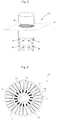
- FIG. 2 is a schematic perspective view of the reactor vessel 10.
- FIG. 3 is a schematic illustration of the cross sectional plane B that is obtained when a cross section of the reactor vessel 10 is taken along plane A.
- the reactor vessel 10 is a container of a triple-tubular structure formed by coaxially arranging a tube 14 having the largest diameter and operating as the outer wall of the reactor vessel 10, a tube 15 having a diameter smaller than the tube 14 and a tube 16 having a diameter smaller than the tube 15.
- the region between the tube 14 and the tube 15 is an external region 11 for generating toluene and hydrogen by dehydrogenation of methylcyclohexane.
- the outer region 11 is provided with a plurality of fins 17 extending in the direction from the tube 14 toward the tube 15.
- the region between the tube 15 and the tube 16 is an inner region 12 for introducing the mixture of fuel (which may be toluene) and air.
- the inner region 12 is provided with a plurality of fins 18 extending in the direction from the tube 15 toward the tube 16.
- the fins 17 and the fins 18 are catalyst supports or supports having respective catalyst supports fitted to the outer surface thereof.
- the catalyst supports are preferably aluminum oxide prepared by way of an anodic oxidation process.
- a combustion catalyst that is required for burning a mixture of fuel and air is supported on the fins 17.
- a dehydrogenation catalyst that is required for dehydrogenation of methylcyclohexane is supported on the fins 18.
- the dehydrogenation catalyst is preferably platinum.
- a catalyst support made of aluminum oxide is a highly heat-resistant catalyst support. Additionally, since the fins 17 and 18 are made of aluminum that is highly thermally conductive, heat can be quickly transmitted from the inner region 12 to the outer region 11.
- the temperature of the dehydrogenation catalyst varies depending on the type of organic hydride, it is preferably within a range between about 270 and 400° C, more preferably within a range between about 285 and 370° C if using methylcyclohexane.
- Catalyst supports having a profile other than fins 17 may be arranged in the outer region 11.
- pleats may be formed on the surface of the tube 14 or 15 and the dehydrogenation catalyst may be made to be supported on the pleats.
- a lattice-shaped or honeycomb-shaped member may be arranged in the outer region 11 and the dehydrogenation catalyst may be made to be supported on the wall surfaces of the member.
- pleats may be formed on the surface of the tube 15 or 16 and the combustion catalyst may be made to be supported on the pleats.
- a lattice-shaped or honeycomb-shaped member may be arranged in the inner region 12 and the combustion catalyst may be made to be supported on the wall surfaces of the member.
- the fins 17, the fins 18, pleats, or a lattice-shaped or honeycomb-shaped member As described above, when the fins 17, the fins 18, pleats, or a lattice-shaped or honeycomb-shaped member is employed, the area supporting the catalyst per unit volume is raised to by turn raise the reaction efficiency.
- catalyst supports having a profile other than the fins 17 may be arranged in the inner region 12.
- a reactor vessel 10 of a triple-tubular structure having an inner region 12 and an outer region 11 arranged outside the inner region 12 and separated from the inner region 12 by a wall so as to contain a dehydrogenation catalyst necessary for dehydrogenation therein, the dehydrogenation catalyst in the outer region 11 is immediately heated by the heat generated as a result of combustion of fuel to immediately raise the efficiency of dehydrogenation and also the rate of hydrogen generation. Since the combustion catalyst and the dehydrogenation catalyst are supported respectively by the fins 17 and the fins 18 in the reactor vessel 10, heat is conducted directly to the dehydrogenation catalyst by way of the surfaces of the fins 17 and the fins 18 without any gas boundary film resistance. Thus, a very high gas utilization efficiency and a very raised hydrogen generation rate can be realized.
- Table 1 shows some of the results obtained by looking into hydrogen generation rates for different methylcyclohexane supply rates.
- Source material supply rate (ml/min) Hydrogen generation rate (NL/min) Conversion ratio (%) 10 5.2 98 30 13.4 85 40 14.3 68
- Hydrogen can be stored safely by a large quantity by utilizing compounds that can store hydrogen on a molecular level by way of hydrogenation such as unsaturated hydrocarbons.
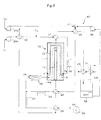
- FIG. 4 is a schematic illustration of a hydrogenation apparatus.
- the hydrogenation apparatus 40 has a reactor vessel 10 that provides a site of hydrogenation of toluene (indicated by "TL” in FIG. 4 ) that is an unsaturated hydrocarbon.
- the reactor vessel 10 shows an oblong cylindrical profile and is a triple-tubular structure formed by radially arranging three tubes.
- the innermost tube of the reactor vessel 10 is a channel 13 for cooling air or cooling water. Both the upstream end and the downstream end of the channel 13 are open to form so many apertures. Heated air or water flows through the channel 13 from upstream to downstream and is discharged from the reactor vessel 10.
- Toluene is hydrogenated in an outer region 11 of the reactor vessel 10 to become methylcyclohexane (indicated by "OHY” in FIG. 4 ), which is an organic hydride, and moves to the outside of the reactor vessel 10 to enter a reaction product container 35.
- the temperature of the hydrogenation catalyst in the reactor vessel 10 is preferably heated to a temperature range between 70 and 250° C. Since hydrogenation is an exothermic reaction, hydrogenation is suppressed and conversely dehydrogenation becomes dominant to reduce the ratio of conversion of toluene into methylcyclohexane when the temperature rises above 250° C. Therefore, the temperature of the hydrogenation catalyst is preferably maintained to a temperature range between 70 and 250° C. A more preferable temperature range for the hydrogenation catalyst is between 80 and 200° C.
- the hydrogenation apparatus 40 differs from the hydrogen generator 1 mainly in that toluene is mixed with hydrogen before it enters the reactor vessel 10 of the hydrogen apparatus 40 and that the substance discharged from the reaction product container 35 contains surplus hydrogen that has not been consumed by hydrogenation. While toluene and hydrogen are mixed between the heat exchanger 30 and the heat exchanger 31 in the embodiment of FIG. 4 , they may alternatively be mixed at a position upstream relative to the heat exchanger 30 or downstream relative to the heat exchanger 31.
- a reactor vessel 10 of a triple-tubular structure having an inner region 12 and an outer region 11 arranged outside the inner region 12 and separated from the inner region 12 by a wall so as to contain a hydrogenation catalyst necessary for hydrogenation therein, the generated heat is immediately removed to raise the efficiency of reaction and also the rate of hydrogenation. Additionally, since cooling air (or cooling water) and the hydrogenation catalyst are held in contact with the fins 17 and the fins 18 in the reactor vessel 10, heat can be removed immediately from the hydrogenation catalyst by way of the wall surfaces of the fins 17 and those of the fins 18. Thus, the hydrogenation rate and the conversion ratio can be further improved.
- the cooling area and the area supporting the catalyst per unit volume is raised to by turn raise the reaction efficiency.
- the catalyst supports made of aluminum oxide are catalyst supports having high heat-resistance. Additionally, since the fins 17 and 18 are made of aluminum that is highly thermally conductive, heat can be quickly transmitted from the inner region 12 to the outer region 11.
- the catalyst supports may be members made of a material such as zirconium oxide or silicon nitride instead of aluminum oxide. Additionally, the catalysts supported by the catalyst supports may be selected from palladium, ruthenium, iridium, rhenium, nickel, molybdenum, tungsten, nitenium, vanadium, osmium, chromium, cobalt, iron or a combination of any of these elements instead of platinum.
- the reactor vessel 10 has a triple-tubular structure.
- the present invention can find applications in the industries that consume or store hydrogen.
Landscapes
- Chemical & Material Sciences (AREA)
- Organic Chemistry (AREA)
- Chemical Kinetics & Catalysis (AREA)
- Engineering & Computer Science (AREA)
- Materials Engineering (AREA)
- Health & Medical Sciences (AREA)
- Physics & Mathematics (AREA)
- General Health & Medical Sciences (AREA)
- Fluid Mechanics (AREA)
- Combustion & Propulsion (AREA)
- Inorganic Chemistry (AREA)
- Mechanical Engineering (AREA)
- General Engineering & Computer Science (AREA)
- Electrochemistry (AREA)
- Plasma & Fusion (AREA)
- Toxicology (AREA)
- Hydrogen, Water And Hydrids (AREA)
- Organic Low-Molecular-Weight Compounds And Preparation Thereof (AREA)
- Filling Or Discharging Of Gas Storage Vessels (AREA)
Applications Claiming Priority (2)
| Application Number | Priority Date | Filing Date | Title |
|---|---|---|---|
| JP2006059027A JP5046359B2 (ja) | 2006-03-06 | 2006-03-06 | 水素発生装置および水素添加反応装置 |
| PCT/JP2007/050057 WO2007102278A1 (ja) | 2006-03-06 | 2007-01-09 | 水素発生装置および水素添加反応装置 |
Publications (3)
| Publication Number | Publication Date |
|---|---|
| EP1995211A1 EP1995211A1 (en) | 2008-11-26 |
| EP1995211A4 EP1995211A4 (en) | 2012-02-29 |
| EP1995211B1 true EP1995211B1 (en) | 2018-03-07 |
Family
ID=38474720
Family Applications (1)
| Application Number | Title | Priority Date | Filing Date |
|---|---|---|---|
| EP07706404.6A Active EP1995211B1 (en) | 2006-03-06 | 2007-01-09 | Hydrogen generator |
Country Status (6)
| Country | Link |
|---|---|
| US (1) | US8057559B2 (enExample) |
| EP (1) | EP1995211B1 (enExample) |
| JP (1) | JP5046359B2 (enExample) |
| CN (1) | CN101437750B (enExample) |
| CA (1) | CA2645114C (enExample) |
| WO (1) | WO2007102278A1 (enExample) |
Families Citing this family (22)
| Publication number | Priority date | Publication date | Assignee | Title |
|---|---|---|---|---|
| US7662435B2 (en) * | 2003-11-12 | 2010-02-16 | Intelligent Energy, Inc. | Method for reducing coking in a hydrogen generation reactor chamber |
| JP5489509B2 (ja) * | 2009-03-31 | 2014-05-14 | 日立エーアイシー株式会社 | 水素触媒部材 |
| JP5489508B2 (ja) * | 2009-03-31 | 2014-05-14 | 日立エーアイシー株式会社 | 水素触媒部材 |
| US8301359B1 (en) | 2010-03-19 | 2012-10-30 | HyCogen Power, LLC | Microprocessor controlled automated mixing system, cogeneration system and adaptive/predictive control for use therewith |
| JP5369126B2 (ja) * | 2010-04-28 | 2013-12-18 | 日本精線株式会社 | 水素化反応/脱水素化反応用のワイヤー触媒成形品 |
| TW201209225A (en) * | 2010-08-31 | 2012-03-01 | Li-Shui Tang | Hydrogen generation apparatus |
| US8568665B2 (en) | 2010-12-28 | 2013-10-29 | Nippon Seisen Co., Ltd. | Catalyst structure and hydrogenation/dehydrogenation reaction module using the same catalyst structure |
| JP5632050B1 (ja) * | 2013-07-12 | 2014-11-26 | 株式会社辰巳菱機 | 脱水素システム |
| JP6244242B2 (ja) * | 2014-03-26 | 2017-12-06 | 千代田化工建設株式会社 | 水素製造システム及び水素製造方法 |
| JP6400410B2 (ja) | 2014-09-25 | 2018-10-03 | 国立大学法人横浜国立大学 | 有機ケミカルハイドライド製造用電解セル |
| CA2966834C (en) | 2014-11-10 | 2022-08-30 | National University Corporation Yokohama National University | Oxygen-generating anode |
| JP6501141B2 (ja) | 2014-11-21 | 2019-04-17 | 国立大学法人横浜国立大学 | 有機ハイドライド製造装置およびこれを用いた有機ハイドライドの製造方法 |
| US9958211B2 (en) | 2015-03-12 | 2018-05-01 | Bayotech, Inc. | Nested-flow heat exchangers and chemical reactors |
| CN104888664B (zh) * | 2015-04-22 | 2017-11-10 | 华东理工大学 | 一种自热供氢装置及其应用 |
| CN105836704B (zh) * | 2016-03-24 | 2017-12-01 | 广西大学 | 一种用于化学制氢的氢气发生装置 |
| DE102016222597A1 (de) | 2016-11-16 | 2018-05-17 | Hydrogenious Technologies Gmbh | Verfahren zum Speichern von Wasserstoffgas, Hydrier-Reaktor und Transport-Container |
| CN108043332A (zh) * | 2018-01-17 | 2018-05-18 | 北京国能中林科技开发有限公司 | 一种应用于液态氢源材料的高效脱氢反应器 |
| JP7049168B2 (ja) * | 2018-04-23 | 2022-04-06 | 株式会社辰巳菱機 | 防災型建築構造物の構築システム |
| JP6998054B2 (ja) * | 2018-11-05 | 2022-01-18 | 株式会社辰巳菱機 | 発電システム |
| KR102176525B1 (ko) * | 2018-11-07 | 2020-11-10 | 한국과학기술원 | 희생층을 이용한 계층적 주름 구조체의 제조방법 및 이로부터 제조된 계층적 주름 구조체 |
| JP7479897B2 (ja) * | 2020-03-30 | 2024-05-09 | Eneos株式会社 | 管理システム、輸送方法、及び管理装置 |
| ES2990042B2 (es) * | 2024-01-11 | 2025-10-10 | Greene Entpr S L | DISPOSITIVO CRAQUEADOR Y PROCESO PARA LA OBTENCION DE HIDROGENO y ACEITES PIROLITICOS |
Family Cites Families (9)
| Publication number | Priority date | Publication date | Assignee | Title |
|---|---|---|---|---|
| JP2004083385A (ja) * | 2002-06-04 | 2004-03-18 | Sekisui Chem Co Ltd | 水素供給媒体およびそれを利用した水素貯蔵・供給システム |
| JP2004168631A (ja) * | 2002-11-22 | 2004-06-17 | Toyota Motor Corp | 水素ガス生成装置 |
| JP2004359494A (ja) * | 2003-06-04 | 2004-12-24 | Toyota Motor Corp | 水素ガス生成装置 |
| FR2862630B1 (fr) * | 2003-11-25 | 2006-07-07 | Renault Sas | Procede de stockage et de destockage d'hydrogene pour l'alimentation de moteurs et piles a combustible |
| JP2005152854A (ja) * | 2003-11-28 | 2005-06-16 | Toyota Motor Corp | 有機ハイドライドの脱水素・水素添加装置及びこれに用いる担体 |
| JP2005289652A (ja) * | 2004-03-09 | 2005-10-20 | Nippon Oil Corp | 水素の製造方法および反応管 |
| JP2005281103A (ja) * | 2004-03-30 | 2005-10-13 | Nippon Oil Corp | 水素の製造法および水素製造システム |
| JP2006248814A (ja) * | 2005-03-09 | 2006-09-21 | Hitachi Ltd | 水素供給装置および水素供給方法 |
| JP2006290644A (ja) * | 2005-04-07 | 2006-10-26 | Densei:Kk | 触媒燃焼を利用した水素供給・貯蔵装置 |
-
2006
- 2006-03-06 JP JP2006059027A patent/JP5046359B2/ja active Active
-
2007
- 2007-01-09 CA CA2645114A patent/CA2645114C/en active Active
- 2007-01-09 WO PCT/JP2007/050057 patent/WO2007102278A1/ja not_active Ceased
- 2007-01-09 US US12/281,869 patent/US8057559B2/en not_active Expired - Fee Related
- 2007-01-09 EP EP07706404.6A patent/EP1995211B1/en active Active
- 2007-01-09 CN CN2007800161529A patent/CN101437750B/zh active Active
Non-Patent Citations (1)
| Title |
|---|
| None * |
Also Published As
| Publication number | Publication date |
|---|---|
| CA2645114C (en) | 2015-02-17 |
| JP2007238341A (ja) | 2007-09-20 |
| JP5046359B2 (ja) | 2012-10-10 |
| US8057559B2 (en) | 2011-11-15 |
| CA2645114A1 (en) | 2007-09-13 |
| EP1995211A1 (en) | 2008-11-26 |
| WO2007102278A1 (ja) | 2007-09-13 |
| CN101437750A (zh) | 2009-05-20 |
| US20090025291A1 (en) | 2009-01-29 |
| EP1995211A4 (en) | 2012-02-29 |
| CN101437750B (zh) | 2013-01-23 |
Similar Documents
| Publication | Publication Date | Title |
|---|---|---|
| EP1995211B1 (en) | Hydrogen generator | |
| JP6728751B2 (ja) | 反応装置及び反応システム | |
| MX2011001868A (es) | Sistemas de celda de combustible que incluyen montajes productores de hidrogeno. | |
| JP2006502070A (ja) | 改質及び水素精製装置 | |
| US7803202B2 (en) | Reformer unit for generating hydrogen from a starting material comprising a hydrocarbon-water mixture | |
| RU2415073C2 (ru) | Компактный реактор реформинга | |
| JP4852358B2 (ja) | 改質器および間接内部改質型固体酸化物形燃料電池 | |
| KR20090086583A (ko) | 개질기, 개질 유닛 및 연료 전지 시스템 | |
| CN100564246C (zh) | 氢生成装置及燃料电池发电系统 | |
| KR20150143080A (ko) | 열전달 성능이 향상된 연료전지용 개질 반응 시스템 | |
| JP4464230B2 (ja) | 改質装置および方法ならびに燃料電池システム | |
| JP2001172003A (ja) | 改質装置 | |
| JP2005022939A (ja) | 水素供給システムの反応装置及び水素供給システム | |
| JP2002003204A (ja) | 燃料改質器 | |
| JP2003321206A (ja) | 単管円筒式改質器 | |
| JP4933818B2 (ja) | 固体酸化物形燃料電池システムの運転方法 | |
| JP4852357B2 (ja) | 改質器および間接内部改質型固体酸化物形燃料電池 | |
| JP5078426B2 (ja) | 一酸化炭素除去器および水素製造装置 | |
| JP4278393B2 (ja) | 水素製造装置および燃料電池システム | |
| JP3719931B2 (ja) | 水素生成器 | |
| JP2010001187A (ja) | 改質装置 | |
| CN101573290B (zh) | 改质器、改质单元及燃料电池系统 | |
| HK1132488A (en) | Hydrogen generator and hydrogenation apparatus | |
| JP2803266B2 (ja) | メタノール改質反応装置 | |
| JPH03199102A (ja) | メタノール改質反応装置 |
Legal Events
| Date | Code | Title | Description |
|---|---|---|---|
| PUAI | Public reference made under article 153(3) epc to a published international application that has entered the european phase |
Free format text: ORIGINAL CODE: 0009012 |
|
| 17P | Request for examination filed |
Effective date: 20081001 |
|
| AK | Designated contracting states |
Kind code of ref document: A1 Designated state(s): AT BE BG CH CY CZ DE DK EE ES FI FR GB GR HU IE IS IT LI LT LU LV MC NL PL PT RO SE SI SK TR |
|
| A4 | Supplementary search report drawn up and despatched |
Effective date: 20120127 |
|
| RIC1 | Information provided on ipc code assigned before grant |
Ipc: B01J 35/04 20060101ALN20120123BHEP Ipc: B01J 23/42 20060101ALN20120123BHEP Ipc: B01J 8/04 20060101ALN20120123BHEP Ipc: F17C 11/00 20060101ALI20120123BHEP Ipc: C01B 3/22 20060101ALI20120123BHEP Ipc: C01B 3/00 20060101AFI20120123BHEP Ipc: B01J 37/34 20060101ALN20120123BHEP Ipc: C01B 3/26 20060101ALN20120123BHEP Ipc: B01J 12/00 20060101ALN20120123BHEP Ipc: B01J 15/00 20060101ALN20120123BHEP Ipc: B01J 21/04 20060101ALN20120123BHEP |
|
| DAX | Request for extension of the european patent (deleted) | ||
| 17Q | First examination report despatched |
Effective date: 20121105 |
|
| GRAP | Despatch of communication of intention to grant a patent |
Free format text: ORIGINAL CODE: EPIDOSNIGR1 |
|
| STAA | Information on the status of an ep patent application or granted ep patent |
Free format text: STATUS: GRANT OF PATENT IS INTENDED |
|
| RIC1 | Information provided on ipc code assigned before grant |
Ipc: F17C 11/00 20060101ALI20170609BHEP Ipc: B01J 21/04 20060101ALN20170609BHEP Ipc: B01J 23/42 20060101ALN20170609BHEP Ipc: C01B 3/26 20060101ALN20170609BHEP Ipc: C01B 3/00 20060101AFI20170609BHEP Ipc: B01J 8/04 20060101ALN20170609BHEP Ipc: B01J 37/34 20060101ALN20170609BHEP Ipc: B01J 35/04 20060101ALN20170609BHEP Ipc: C01B 3/22 20060101ALI20170609BHEP Ipc: B01J 12/00 20060101ALN20170609BHEP Ipc: B01J 15/00 20060101ALN20170609BHEP |
|
| INTG | Intention to grant announced |
Effective date: 20170717 |
|
| GRAS | Grant fee paid |
Free format text: ORIGINAL CODE: EPIDOSNIGR3 |
|
| RAP1 | Party data changed (applicant data changed or rights of an application transferred) |
Owner name: HREIN ENERGY, INC. Owner name: ICHIKAWA, MASARU |
|
| RAP1 | Party data changed (applicant data changed or rights of an application transferred) |
Owner name: HREIN ENERGY, INC. Owner name: ICHIKAWA, MASARU |
|
| GRAA | (expected) grant |
Free format text: ORIGINAL CODE: 0009210 |
|
| STAA | Information on the status of an ep patent application or granted ep patent |
Free format text: STATUS: THE PATENT HAS BEEN GRANTED |
|
| AK | Designated contracting states |
Kind code of ref document: B1 Designated state(s): AT BE BG CH CY CZ DE DK EE ES FI FR GB GR HU IE IS IT LI LT LU LV MC NL PL PT RO SE SI SK TR |
|
| REG | Reference to a national code |
Ref country code: GB Ref legal event code: FG4D |
|
| REG | Reference to a national code |
Ref country code: CH Ref legal event code: EP Ref country code: AT Ref legal event code: REF Ref document number: 976335 Country of ref document: AT Kind code of ref document: T Effective date: 20180315 |
|
| REG | Reference to a national code |
Ref country code: IE Ref legal event code: FG4D |
|
| REG | Reference to a national code |
Ref country code: DE Ref legal event code: R096 Ref document number: 602007054134 Country of ref document: DE |
|
| REG | Reference to a national code |
Ref country code: NL Ref legal event code: MP Effective date: 20180307 |
|
| REG | Reference to a national code |
Ref country code: LT Ref legal event code: MG4D |
|
| PG25 | Lapsed in a contracting state [announced via postgrant information from national office to epo] |
Ref country code: FI Free format text: LAPSE BECAUSE OF FAILURE TO SUBMIT A TRANSLATION OF THE DESCRIPTION OR TO PAY THE FEE WITHIN THE PRESCRIBED TIME-LIMIT Effective date: 20180307 Ref country code: ES Free format text: LAPSE BECAUSE OF FAILURE TO SUBMIT A TRANSLATION OF THE DESCRIPTION OR TO PAY THE FEE WITHIN THE PRESCRIBED TIME-LIMIT Effective date: 20180307 Ref country code: CY Free format text: LAPSE BECAUSE OF FAILURE TO SUBMIT A TRANSLATION OF THE DESCRIPTION OR TO PAY THE FEE WITHIN THE PRESCRIBED TIME-LIMIT Effective date: 20180307 Ref country code: LT Free format text: LAPSE BECAUSE OF FAILURE TO SUBMIT A TRANSLATION OF THE DESCRIPTION OR TO PAY THE FEE WITHIN THE PRESCRIBED TIME-LIMIT Effective date: 20180307 |
|
| REG | Reference to a national code |
Ref country code: AT Ref legal event code: MK05 Ref document number: 976335 Country of ref document: AT Kind code of ref document: T Effective date: 20180307 |
|
| PG25 | Lapsed in a contracting state [announced via postgrant information from national office to epo] |
Ref country code: LV Free format text: LAPSE BECAUSE OF FAILURE TO SUBMIT A TRANSLATION OF THE DESCRIPTION OR TO PAY THE FEE WITHIN THE PRESCRIBED TIME-LIMIT Effective date: 20180307 Ref country code: SE Free format text: LAPSE BECAUSE OF FAILURE TO SUBMIT A TRANSLATION OF THE DESCRIPTION OR TO PAY THE FEE WITHIN THE PRESCRIBED TIME-LIMIT Effective date: 20180307 Ref country code: BG Free format text: LAPSE BECAUSE OF FAILURE TO SUBMIT A TRANSLATION OF THE DESCRIPTION OR TO PAY THE FEE WITHIN THE PRESCRIBED TIME-LIMIT Effective date: 20180607 Ref country code: GR Free format text: LAPSE BECAUSE OF FAILURE TO SUBMIT A TRANSLATION OF THE DESCRIPTION OR TO PAY THE FEE WITHIN THE PRESCRIBED TIME-LIMIT Effective date: 20180608 |
|
| PG25 | Lapsed in a contracting state [announced via postgrant information from national office to epo] |
Ref country code: RO Free format text: LAPSE BECAUSE OF FAILURE TO SUBMIT A TRANSLATION OF THE DESCRIPTION OR TO PAY THE FEE WITHIN THE PRESCRIBED TIME-LIMIT Effective date: 20180307 Ref country code: EE Free format text: LAPSE BECAUSE OF FAILURE TO SUBMIT A TRANSLATION OF THE DESCRIPTION OR TO PAY THE FEE WITHIN THE PRESCRIBED TIME-LIMIT Effective date: 20180307 Ref country code: NL Free format text: LAPSE BECAUSE OF FAILURE TO SUBMIT A TRANSLATION OF THE DESCRIPTION OR TO PAY THE FEE WITHIN THE PRESCRIBED TIME-LIMIT Effective date: 20180307 Ref country code: PL Free format text: LAPSE BECAUSE OF FAILURE TO SUBMIT A TRANSLATION OF THE DESCRIPTION OR TO PAY THE FEE WITHIN THE PRESCRIBED TIME-LIMIT Effective date: 20180307 |
|
| PG25 | Lapsed in a contracting state [announced via postgrant information from national office to epo] |
Ref country code: SK Free format text: LAPSE BECAUSE OF FAILURE TO SUBMIT A TRANSLATION OF THE DESCRIPTION OR TO PAY THE FEE WITHIN THE PRESCRIBED TIME-LIMIT Effective date: 20180307 Ref country code: CZ Free format text: LAPSE BECAUSE OF FAILURE TO SUBMIT A TRANSLATION OF THE DESCRIPTION OR TO PAY THE FEE WITHIN THE PRESCRIBED TIME-LIMIT Effective date: 20180307 Ref country code: AT Free format text: LAPSE BECAUSE OF FAILURE TO SUBMIT A TRANSLATION OF THE DESCRIPTION OR TO PAY THE FEE WITHIN THE PRESCRIBED TIME-LIMIT Effective date: 20180307 |
|
| REG | Reference to a national code |
Ref country code: DE Ref legal event code: R097 Ref document number: 602007054134 Country of ref document: DE |
|
| PG25 | Lapsed in a contracting state [announced via postgrant information from national office to epo] |
Ref country code: PT Free format text: LAPSE BECAUSE OF FAILURE TO SUBMIT A TRANSLATION OF THE DESCRIPTION OR TO PAY THE FEE WITHIN THE PRESCRIBED TIME-LIMIT Effective date: 20180709 |
|
| PLBE | No opposition filed within time limit |
Free format text: ORIGINAL CODE: 0009261 |
|
| STAA | Information on the status of an ep patent application or granted ep patent |
Free format text: STATUS: NO OPPOSITION FILED WITHIN TIME LIMIT |
|
| PG25 | Lapsed in a contracting state [announced via postgrant information from national office to epo] |
Ref country code: DK Free format text: LAPSE BECAUSE OF FAILURE TO SUBMIT A TRANSLATION OF THE DESCRIPTION OR TO PAY THE FEE WITHIN THE PRESCRIBED TIME-LIMIT Effective date: 20180307 |
|
| 26N | No opposition filed |
Effective date: 20181210 |
|
| PG25 | Lapsed in a contracting state [announced via postgrant information from national office to epo] |
Ref country code: IT Free format text: LAPSE BECAUSE OF FAILURE TO SUBMIT A TRANSLATION OF THE DESCRIPTION OR TO PAY THE FEE WITHIN THE PRESCRIBED TIME-LIMIT Effective date: 20180307 Ref country code: SI Free format text: LAPSE BECAUSE OF FAILURE TO SUBMIT A TRANSLATION OF THE DESCRIPTION OR TO PAY THE FEE WITHIN THE PRESCRIBED TIME-LIMIT Effective date: 20180307 |
|
| PG25 | Lapsed in a contracting state [announced via postgrant information from national office to epo] |
Ref country code: MC Free format text: LAPSE BECAUSE OF FAILURE TO SUBMIT A TRANSLATION OF THE DESCRIPTION OR TO PAY THE FEE WITHIN THE PRESCRIBED TIME-LIMIT Effective date: 20180307 |
|
| REG | Reference to a national code |
Ref country code: CH Ref legal event code: PL |
|
| PG25 | Lapsed in a contracting state [announced via postgrant information from national office to epo] |
Ref country code: LU Free format text: LAPSE BECAUSE OF NON-PAYMENT OF DUE FEES Effective date: 20190109 |
|
| REG | Reference to a national code |
Ref country code: BE Ref legal event code: MM Effective date: 20190131 |
|
| REG | Reference to a national code |
Ref country code: IE Ref legal event code: MM4A |
|
| PG25 | Lapsed in a contracting state [announced via postgrant information from national office to epo] |
Ref country code: BE Free format text: LAPSE BECAUSE OF NON-PAYMENT OF DUE FEES Effective date: 20190131 |
|
| PG25 | Lapsed in a contracting state [announced via postgrant information from national office to epo] |
Ref country code: CH Free format text: LAPSE BECAUSE OF NON-PAYMENT OF DUE FEES Effective date: 20190131 Ref country code: LI Free format text: LAPSE BECAUSE OF NON-PAYMENT OF DUE FEES Effective date: 20190131 |
|
| PG25 | Lapsed in a contracting state [announced via postgrant information from national office to epo] |
Ref country code: IE Free format text: LAPSE BECAUSE OF NON-PAYMENT OF DUE FEES Effective date: 20190109 |
|
| PG25 | Lapsed in a contracting state [announced via postgrant information from national office to epo] |
Ref country code: TR Free format text: LAPSE BECAUSE OF FAILURE TO SUBMIT A TRANSLATION OF THE DESCRIPTION OR TO PAY THE FEE WITHIN THE PRESCRIBED TIME-LIMIT Effective date: 20180307 |
|
| PG25 | Lapsed in a contracting state [announced via postgrant information from national office to epo] |
Ref country code: IS Free format text: LAPSE BECAUSE OF FAILURE TO SUBMIT A TRANSLATION OF THE DESCRIPTION OR TO PAY THE FEE WITHIN THE PRESCRIBED TIME-LIMIT Effective date: 20180707 |
|
| PG25 | Lapsed in a contracting state [announced via postgrant information from national office to epo] |
Ref country code: HU Free format text: LAPSE BECAUSE OF FAILURE TO SUBMIT A TRANSLATION OF THE DESCRIPTION OR TO PAY THE FEE WITHIN THE PRESCRIBED TIME-LIMIT; INVALID AB INITIO Effective date: 20070109 |
|
| PGFP | Annual fee paid to national office [announced via postgrant information from national office to epo] |
Ref country code: GB Payment date: 20220131 Year of fee payment: 16 |
|
| PGFP | Annual fee paid to national office [announced via postgrant information from national office to epo] |
Ref country code: FR Payment date: 20220110 Year of fee payment: 16 |
|
| P01 | Opt-out of the competence of the unified patent court (upc) registered |
Effective date: 20230428 |
|
| GBPC | Gb: european patent ceased through non-payment of renewal fee |
Effective date: 20230109 |
|
| PG25 | Lapsed in a contracting state [announced via postgrant information from national office to epo] |
Ref country code: GB Free format text: LAPSE BECAUSE OF NON-PAYMENT OF DUE FEES Effective date: 20230109 |
|
| PG25 | Lapsed in a contracting state [announced via postgrant information from national office to epo] |
Ref country code: FR Free format text: LAPSE BECAUSE OF NON-PAYMENT OF DUE FEES Effective date: 20230131 |
|
| PGFP | Annual fee paid to national office [announced via postgrant information from national office to epo] |
Ref country code: DE Payment date: 20250131 Year of fee payment: 19 |