EP1995180A1 - Kunststofftube - Google Patents
Kunststofftube Download PDFInfo
- Publication number
- EP1995180A1 EP1995180A1 EP08016133A EP08016133A EP1995180A1 EP 1995180 A1 EP1995180 A1 EP 1995180A1 EP 08016133 A EP08016133 A EP 08016133A EP 08016133 A EP08016133 A EP 08016133A EP 1995180 A1 EP1995180 A1 EP 1995180A1
- Authority
- EP
- European Patent Office
- Prior art keywords
- cylinder
- container
- neck portion
- depending
- cover plate
- Prior art date
- Legal status (The legal status is an assumption and is not a legal conclusion. Google has not performed a legal analysis and makes no representation as to the accuracy of the status listed.)
- Granted
Links
Images


Classifications
-
- B—PERFORMING OPERATIONS; TRANSPORTING
- B65—CONVEYING; PACKING; STORING; HANDLING THIN OR FILAMENTARY MATERIAL
- B65D—CONTAINERS FOR STORAGE OR TRANSPORT OF ARTICLES OR MATERIALS, e.g. BAGS, BARRELS, BOTTLES, BOXES, CANS, CARTONS, CRATES, DRUMS, JARS, TANKS, HOPPERS, FORWARDING CONTAINERS; ACCESSORIES, CLOSURES, OR FITTINGS THEREFOR; PACKAGING ELEMENTS; PACKAGES
- B65D35/00—Pliable tubular containers adapted to be permanently or temporarily deformed to expel contents, e.g. collapsible tubes for toothpaste or other plastic or semi-liquid material; Holders therefor
- B65D35/44—Closures
-
- B—PERFORMING OPERATIONS; TRANSPORTING
- B65—CONVEYING; PACKING; STORING; HANDLING THIN OR FILAMENTARY MATERIAL
- B65D—CONTAINERS FOR STORAGE OR TRANSPORT OF ARTICLES OR MATERIALS, e.g. BAGS, BARRELS, BOTTLES, BOXES, CANS, CARTONS, CRATES, DRUMS, JARS, TANKS, HOPPERS, FORWARDING CONTAINERS; ACCESSORIES, CLOSURES, OR FITTINGS THEREFOR; PACKAGING ELEMENTS; PACKAGES
- B65D47/00—Closures with filling and discharging, or with discharging, devices
- B65D47/04—Closures with discharging devices other than pumps
- B65D47/06—Closures with discharging devices other than pumps with pouring spouts or tubes; with discharge nozzles or passages
- B65D47/08—Closures with discharging devices other than pumps with pouring spouts or tubes; with discharge nozzles or passages having articulated or hinged closures
- B65D47/0804—Closures with discharging devices other than pumps with pouring spouts or tubes; with discharge nozzles or passages having articulated or hinged closures integrally formed with the base element provided with the spout or discharge passage
- B65D47/0809—Closures with discharging devices other than pumps with pouring spouts or tubes; with discharge nozzles or passages having articulated or hinged closures integrally formed with the base element provided with the spout or discharge passage and elastically biased towards both the open and the closed positions
-
- B—PERFORMING OPERATIONS; TRANSPORTING
- B65—CONVEYING; PACKING; STORING; HANDLING THIN OR FILAMENTARY MATERIAL
- B65D—CONTAINERS FOR STORAGE OR TRANSPORT OF ARTICLES OR MATERIALS, e.g. BAGS, BARRELS, BOTTLES, BOXES, CANS, CARTONS, CRATES, DRUMS, JARS, TANKS, HOPPERS, FORWARDING CONTAINERS; ACCESSORIES, CLOSURES, OR FITTINGS THEREFOR; PACKAGING ELEMENTS; PACKAGES
- B65D35/00—Pliable tubular containers adapted to be permanently or temporarily deformed to expel contents, e.g. collapsible tubes for toothpaste or other plastic or semi-liquid material; Holders therefor
- B65D35/02—Body construction
- B65D35/10—Body construction made by uniting or interconnecting two or more components
-
- B—PERFORMING OPERATIONS; TRANSPORTING
- B65—CONVEYING; PACKING; STORING; HANDLING THIN OR FILAMENTARY MATERIAL
- B65D—CONTAINERS FOR STORAGE OR TRANSPORT OF ARTICLES OR MATERIALS, e.g. BAGS, BARRELS, BOTTLES, BOXES, CANS, CARTONS, CRATES, DRUMS, JARS, TANKS, HOPPERS, FORWARDING CONTAINERS; ACCESSORIES, CLOSURES, OR FITTINGS THEREFOR; PACKAGING ELEMENTS; PACKAGES
- B65D2401/00—Tamper-indicating means
- B65D2401/15—Tearable part of the closure
- B65D2401/25—Non-metallic tear-off strips
Definitions
- Present invention relates to a synthetic resin made tube container.
- This container consists of a container body 101 including a trunk portion 102 with an upper end from which a neck portion 104 is erecting through a shoulder 103; and of a cover body 105 including a top wall 107 closing an upper face of the neck portion 104 and having a discharge cylinder 106, a mounting cylinder 108 which is depending from a lower periphery of the discharge cylinder 106 for providing a screw engagement with the outside of the neck portion, and a cover tube 109 depending from the circumference of the top wall, and a cover plate 110 with an outer edge from which a circumferential wall 111 is depending, said circumferential wall being connected to the top wall 107 via a thin hinge 112.
- the mounting cylinder 108 is fitted on the neck portion 104 by screwing thereto.
- screw threads have to be formed for a certain, sufficient vertical range, so that both of the neck portion and the mounting cylinder, which are overlapping as a double cylinder, are have to be made long, interrupting reduction of the material for manufacturing the container. This not only increases its manufacturing cost but also the amount of waste when the containers are done away with.
- the above-mentioned container is provided with the top wall from the circumference of which the cover tube is depending for facilitating rotation operation with respect to the neck portion.
- the outer circumferential portion of the top wall and the shoulder are overlapping generally as an upper and lower double wall, so that in this aspect also, the material for forming the container is used in vain.
- a cover body 105 has a top wall 107 from an outer edge of which a mounting cylinder 108 for fixing on the neck portion is depending. Still more, there is a room for economizing the material for forming this container by separating the top wall 107 and the mounting cylinder 108, and connecting the periphery of the top wall to an inside of the upper end portion of the neck portion.
- the present applicant proposes a container having a neck portion erecting from a trunk portion, and a top wall closing an upper surface of the neck portion and having a discharge port, a deep groove formed by recessing the rear portion of the top wall, and a thrusting plate which is depending from the back of the cover plate through a hinge mechanism and inserted into the deep groove (Japanese Utility Model Laid Open No. 63-67451 ).
- a container having a neck portion erecting from a trunk portion, and a top wall closing an upper surface of the neck portion and having a discharge port, a deep groove formed by recessing the rear portion of the top wall, and a thrusting plate which is depending from the back of the cover plate through a hinge mechanism and inserted into the deep groove.
- a primary purpose of the present invention is to remove the overlapping double wall structure to economize the material for forming the container.
- a synthetic resin made tube container comprising a container body having a neck portion erecting from a trunk portion through an inward flanged wall on which a fitting recessed groove is circumferentially formed, and a top wall closing the upper surface of the neck portion and having a discharge port; a cap body having a cover plate and an insert cylinder which is connected to the cover plate via a hinge and inserted into the fitting recessed groove.
- A-secondary purpose of the present invention is to eliminate a structure in which the top wall and the shoulder overlapping in upper and lower sides.
- the present invention proposes a synthetic resin made tube container having a mounting cylinder fitted into the upper portion of a trunk portion, said mounting cylinder having a lower part from which a neck portion is erecting through an inward flanged wall, such that a fitting recessed groove is formed between the inside of the mounting cylinder and the outside of the neck portion.
- a third purpose of the present invention is to provide a synthetic resin made tube container having a sealing function for preventing an unintentional opening.
- the cover plate of the container is provided at its circumference with a depending cylinder to which an anti-opening plate is attached. Said anti-opening plate is adhered forcibly removably to the outside of the trunk portion.
- a fourth purpose of the present invention is to prevent an unauthorized opening of the cover plate.
- a synthetic resin made tube container which is sealed by providing a depending cylinder at the circumference thereof with the anti-opening plate which is attached forcibly removably to the outside of the trunk portion. Otherwise, the container may be sealed by providing at the circumference of the cover plate with a depending cylinder having an intermediate portion, a part of which is formed into a hinge, while a remainder thereof being formed into a removable belt.
- a fifth purpose of the present invention is to propose a cap body fitting on a neck portion and having a cover plate which is free from striking against a shoulder of the container in opening the cover plate, when the neck portion is shorten in its vertical length for economizing the material for forming it.
- a synthetic resin made tube container having a cap body with an angular portion between the cover plate and a depending cylinder, said angular portion being chamfered to form a slant wall, such that the angular portion does not strike against the shoulder.
- a six purpose of the present invention is to provide an another type of synthetic resin made tube container in which the material for forming it is economized.
- Said container has a trunk portion with a shoulder from which a short neck portion is erecting, with an upper face of the neck portion being closed by a top wall having a discharge port, and a cover plate having at its rear portion with a flat insert plate which is depending therefrom through a hinge mechanism.
- Said insert plate is inserted into a deep groove which is formed at a rear end portion of the top wall and extending narrowly into left and right direction.
- a seventh purpose of the present invention is to prevent unfavorable rotation of a cover plate.
- the present invention provides a synthetic resin tube container including a fitting cylinder fixed on the outside of the neck portion, and a cover plate which is mounted through the fitting cylinder, wherein a vertical groove and a vertical ridge for providing mutual engagement are formed on the outside of the neck portion and the inside of the fitting cylinder.
- An eighth purpose of the present invention is to provide a synthetic resin tube container in which a length between an upper end of its trunk portion and an upper surface of the cover plate is further shorten.
- the container includes a neck portion and a fitting cylinder fixed thereon, said fitting cylinder having at its lower part an outwardly extended plate circumferentially formed for resting a depending cylinder thereon, while a part of the depending cylinder is connected to the outwardly extended plate through a hinge.
- a ninth purpose of the present invention is to provide a synthetic resin made tube container having one or more of breaking piece or a removable belt between a fitting cylinder and a cover plate.
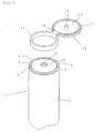
- Figs. 1 to 3 shows a first embodiment of the present invention.
- Numeral 1 designates a container body having an elastically squeezable trunk portion 2, from which a wide mouthed neck portion 4 is erecting through an inward flanged wall 3.
- An upper surface of the neck portion 4 is closed by a top wall 6 with a discharge port 5, and a top opened fitting recessed groove 7 is circumferentially formed on the inward flanged wall 3.
- the trunk portion 2 is formed into a cylinder with a top end opened and a lower end closed by heat or supersonic welding.
- a short mounting cylinder 9 is fitted water-tightly into the upper end of the trunk portion 2.
- Said mounting cylinder 9 is depending from an inner edge of an outward flange 8 resting on the upper end of the trunk portion 2, while a lower end of the mounting cylinder 9 is connected to the inward flanged wall 3 having an inner circumference from which the neck portion 4 is erecting.
- the neck portion 4 and the mounting cylinder 9 are arranged to form inner and outer two cylinders with a small interval therebetween, such that the fitting recessed groove 7 is formed between the two cylinders.
- the shown mounting cylinder 9 and the trunk portion 2 are made as separate members, but they can be formed as an integral member.
- the neck portion 4 is formed into a short cylinder, a length of which is generally equal to that of the mounting cylinder 9.
- the outward flange 8 and the top wall 6 for closing the upper end of the neck portion are positioned at generally the same level, so as to minimizing the height from the upper end of the trunk portion 2 to the upper side of a later-described cover plate without decreasing the volume of the container.
- a discharge cylinder is erecting from the center of the top wall 6, opening the discharge port 5 at its upper end.
- Numeral 11 designates a cap body.
- Said cap body comprises an insert cylinder 12 which has a length generally equal to the depth of the fitting recessed groove 7 and is fitted thereinto, and a cover plate 13 with a circumference from which a depending cylinder 14 is extending downwardly.
- the depending cylinder is resting on the the upper side of the insert cylinder, and the lower end of the depending cylinder 14 and the upper end of the insert cylinder 12 are connected through a thin hinge 15.
- a plug 16 for closing the discharge port is depending from the center of the cover plate 13.
- the top wall 6 is merging into the mounting cylinder 9 fitted into the upper end portion of the trunk portion 2, such that the present container does not need a screw mechanism for fixing the neck portion to the mounting cylinder depending from the top wall, as the conventional container in Fig. 59 does. Accordingly, it is not necessary to form the cover cylinder for rotating the mounting cylinder, nor the top wall portion for depending the cover cylinder, such that there is no inconvenience that the top wall portion and the shoulder are overlapping.
- the container body 1, the top wall 6, and cap body 11 can be made of synthetic resin.
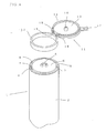
- Figs. 4 to 6 show a second embodiment of the present invention.
- the elements which are substantially equal to that of the first embodiment are designated by the numerals and then the explanation thereon should be omitted.
- the depending cylinder 14 has a front portion from an outside of which an anti-opening plate 17 is depending.
- the lower portion of the anti-opening plate 17 is forcibly removably attached to the front upper portion of the trunk portion 2 by welding so as to prevent an unauthorized opening.
- the inward flanged wall 3 disclosed in the first embodiment is attached to the inner surface of a vertically intermediate portion of the mounting cylinder 9. And also, at the both sides of the thin hinge 15, a pair of springs 18 are formed for enabling an elastic turnover on the thin hinge.
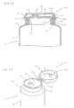
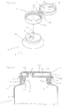
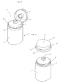
- Figs. 7 to 12 show a third embodiment of the present invention.
- a primary feature of this embodiment is to provide the cap body according to the first embodiment with a seal mechanism.
- the elements substantially equal to those in the first embodiment are designated by the same number, and then omitting the explanation thereon.
- the upper end portion of the trunk portion 2 is formed into a tapering cylinder 2a having a larger diameter at its low end, and the mounting cylinder 9 has a lower portion 9a which is fitted into the tapering cylinder, and the inner flanged wall 3 is attached to an intermediate portion (or the upper end of the lower portion) of the mounting cylinder 9, and the neck portion is erecting shortly from the inner periphery of the inward flanged wall 3.
- the mounting cylinder also has an upper portion 9b which is further shorter than the neck portion 4, and the fitting recessed groove 7 is formed between the neck portion and the upper portion of the mounting cylinder.
- the depending cylinder 14 is extending downwardly as a peripheral wall.
- the depending cylinder 14 comprises a lower cylindrical portion 14a which is fitted into the fitting recessed groove 7 as the insert cylinder of the first embodiment, an upper cylindrical portion 14b which is attached directly to the circumference of the cover plate, and an intermediate cylindrical portion 14c which is merging into the lower cylindrical portion 14a and the upper cylindrical portion 14b.
- a part of the intermediate cylindrical portion 14c is formed into a hinge portion 21, while the remainder of the same is formed into a removable belt 22 which is enclosed by a breaking line.
- a pair of first breaking lines 23a, 23b are formed at the upper and lower ends of the removable belt 22 for departing it from the upper and lower cylindrical portions
- a pair of second breaking lines 24a, 24b are formed at the circumferential ends of the removable belt for departing it from the hinge portion 21.
- a knob 25 for tearing off the breaking lines is provided at the circumferential end of the removable belt 22 at the vicinity of the hinge portion 21.
- the knob 25 is formed into a L-shape protruding into a direction opposite to the hinge portion 21 as shown in the drawings.
- Figs. 13 and 14 show a fourth embodiment of the present invention.
- the container according to the present embodiment has a short neck portion, and in relation to this, is adapted to prevent its shoulder from hitting against one end of a cover plate attached by a hinge.
- a container body 1 has, as it does in the first embodiment, has an elastically squeezable, trunk portion 2 from which a large-diameter neck portion 4 is erecting shortly through a tapering shoulder 31, while a top surface of the neck portion 4 is closed by a top wall 6 with a discharge port 5.
- a short discharge cylinder may preferably be standing from the circumference of the discharge port as shown in the drawing.
- a clipping cylinder 32 is standing from a generally intermediate portion of the shoulder 31 and encircling the neck portion 4, so as to form a fitting recessed groove 7 between the clipping cylinder and the neck portion.
- the neck portion 4 has a lower half portion 4a from which an upper half portion 4b having a small external diameter through a step portion.
- first and second engagement ridge 33, 34 are respectively provided on the upper edges of the lower half portion 4a and the upper half portion 4b of the neck portion except one side of the neck portion (back side of the same in the shown embodiment).
- the lower half portion 4a is provided at the one side of the neck portion with a suitable number of first rotation-resisting ridges 35 extending vertically.
- a notched groove 36 for receiving a later-described hinge is formed at the back portion of the clipping cylinder 32, so as to reduce the height from the upper end of the trunk portion 2 to the upper face of the cover plate 13.
- a cap body 11 has a ring-shaped basic portion 37 which 1s mounted to the neck portion 4.
- the ring-shaped basic portion 37 has an insert cylinder 12 fitted irremovably into the fitting recessed groove 7.
- the ring-shaped basic portion 37 may be formed by fitting the insert cylinder 12 into the fitting recessed groove, forming at the top of the insert cylinder an inward flange, from which a fixing cylinder 38 with a small external diameter is standing, and then fixing the fixing cylinder 38 firmly on the upper half portion of the neck portion at the outside thereof.
- a pair of third and fourth engagement ridges 39, 40 are formed at the insert cylinder 12 and the fixing cylinder 38 for engaging with the lower surfaces of the first and second engagement ridges 33, 34 respectively.
- a second rotation resisting ridge 41 for engaging with the first rotation resisting ridge 35 is formed at the inner face of the back portion of the insert cylinder 12.
- the ring-shaped basic portion 37 is connected to a depending cylinder 14 at the lower end of its back portion through a thin hinge 15.
- Said depending cylinder 14 is depending from the circumference of the cover plate 13, while the upper surface of the cover plate 13 is formed into a horizontal flat surface defining a ground contacting surface, usable in the inverted posture of the container.
- the depending cylinder 14 is provided at the inner face of its front with a rib for engaging with the lower another rib formed laterally on the front of the fixing cylinder 38.
- a cylindrical plug 16 for closing the discharge port 5 is depending from the lower surface of the cover plate 13.
- a joint or a connecting portion between the upper rear portion of the depending cylinder 14 and the rear portion of the cover plate 13 is chamferred as shown in Fig. 13 to form a slant wall 43 for preventing it from hitting against the shoulder when the cover plate is opened.
- the slant wall is sloping from an upper front to a lower back direction, such that the upper surface of the slant wall may come closer to or contact with an angular portion 44 at the circumference of the shoulder in an opened cover state, but the slant wall does not hit against the angular portion.
- the hinge is not damaged, nor the cap body slips out from the neck portion due to the hitting.
- Fig. 15 shows a fifth embodiment of the present invention.
- the fitting recessed groove 7 mentioned above is formed in the cap body, while the insert cylinder is formed in the container body.
- the explanation on the element which is the same to that of the fourth embodiment is omitted.
- a container body 1 has a trunk portion 2 from which a neck portion 4 is erecting through a shoulder 31, and the upper portion of the neck portion is formed into an insert cylinder 12.
- the cap body 11 has a ring-shaped basic portion 37, from the underside of which a double cylinder 45 is depending.
- the double cylinder consists of an inner cylinder and an outer cylinder, between which a fitting recessed groove 7 opened downward is formed.
- the insert cylinder 12 is irremovably fixed into the fitting recessed groove, such that the cap body is mounted to the neck portion.
- the upper face of the ring-shaped basic portion 37 is closed by a top wall 6 with a discharge port 5. Said top wall is integrally formed with the ring-shaped basic portion.
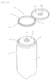
- Figs. 16 to 18 show a sixth embodiment of the present invention.
- This embodiment proposes a cap body with a flat insert plate instead of the insert cylinder shown in the first embodiment.
- a container body 1 has an elastically squeezable, trunk portion 2 from which a neck portion 4 is erecting through a shoulder 31, and the upper surface of the neck portion is closed by a top wall 6 with a discharge port 5. It is preferable that the top wall, the neck portion, and the shoulder are formed into an integral head portion 51, and the lower end of the shoulder is connected with and merging into the upper end of the trunk portion 2.
- This construction may be formed by a socalled down-process method shown in Japanese Patent Publication No. 38 (A.D.1963)-23485 .
- a synthetic resin sheet is punched by a cylindrical cutter for stamping out a disc, the periphery of which is connected by welding to the leading end of a synthetic resin sleeve for forming a trunk portion having an outer diameter equal to the inner diameter of the cylindrical cutter, and then the disc is compressed into the head portion.
- the head portion may be made of injection molding, and the lower end of the head portion is welded to the upper end of the trunk portion by heat or highfrequency wave.
- the top wall 6 has one side, a back side for example, which is recessed to form a deep groove 52 for fixing a later described insert plate.
- the deep groove has a narrow shape extending into the left and right in a top view shown in Fig. 18 , or circumferential direction of the neck portion.
- the deep groove 52 has a depth which is generally equal to the neck portion, such that the neck portion 4 may be formed as short as possible, while securing a required length of the insert plate.
- the neck portion 4 has a rear wall 53, the front surface of which forms a rear side of inner wall surface of the deep groove 52.
- the rear wall 53 may have at a lower part of its front face a blind hole or a through hole, for example an engagement hole 54 opening back and forth as shown, for engaging with a later-described engagement projection. Moreover, the rear wall 53 also has an upper end surface with its lengthwise intermediate portion is recessed to form a fitting recess 55 for resting a later-described elastic band plate. Furthermore, an annular step 6a for resting the lower end of the later-described depending cylinder 14 is formed at the circumference of the top wall as shown in the drawing.
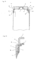
- a cap body 11 has a cover plate 13 from a periphery of which a depending cylinder 14 is extending downwards, and an insert plate 57 which is depending through a hinge mechanism 56 from the lower end of a rear portion of the depending cylinder 14.
- the insert plate 57 is fitted into the deep groove 52 so as to connect the cap body 11 to the head portion 51 of the container body.
- the hinge mechanism 56 may preferably comprises, as shown in the drawings, a pair of first hinges 56a, 56a for connecting the left and right sides of the upper end of the insert plate 57 to the lower end of the rear portion of the depending cylinder 14, and a second hinge 56b formed between the first hinges.
- the second hinge 56b has a band-like elastic plate 58 which has a zigzag section and connects the intermediate portion of the insert plate to the lower end of the depending cylinder 14. Due to the zigzag section, the elastic band has a larger allowance for elastic deformation for preventing that an excessive stress is concentrated on a joint between the ends of the elastic band and the cover plate or the insert plate, even in a tube container having a short neck portion, which is a subject matter of the present invention.
- the basic structure i.e., a zigzag sectional configuration, which is common to that of international application PCT/CH92/00021 (i.e. Japanese patent Laid Open No. 5 (A.D. 1993)-505786 ).
- the lower end of the elastic plate 58 is connected to the lengthwise intermediate portion of the insert plate at its outside, not to the upper end of the insert plate. More in detail, the said plate has an upper part which is exposed to an outside through the fitting recess 55, and a lower end portion of the elastic plate is protruding outwards from the lower end of the upper part and placed on the fitting recess, while the remainder of the elastic plate is bent and standing up from the lower end portion of the same.
- the insert plate 57 is provided at its lower end portion with an engagement projection 59 projecting backwards from the lower end portion and engaging with the engagement hole so as to prevent the insert plate from slipping out upwards.
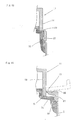
- Figs. 19 to 21 show a seventh embodiment.
- This embodiment is generally corresponding to the six embodiment, except that a deep groove 52 has a front wall which is provided at its lower portion with an engagement hole 60, and an engagement projection 59 which is protruding forward from the lower end of the insert plate 57 and inserted into the engagement hole 60.
- the explanation on other elements which are the same to those of the six embodiment is omitted.
- Figs. 22 to 24 show an eighth embodiment of the present invention.
- This embodiment is also generally corresponding to the six embodiment, except that the hinge mechanism disclosed therein is replaced by a known, three point hinge mechanism.
- This three point hinge is formed by removing a zigzag elastic plate from the hinge mechanism in the six embodiment, while a notch 61 is formed at the cover plate and depending cylinder from a portion between the the pair of the first hinges to the rear portion of the cover plate.
- a band-like elastic band 58 is connecting the front end of of the notch to the rear side of the insert plate 57.
- Figs 25 to 27 show a ninth embodiment of the present invention.
- This embodiment is generally corresponding to the eighth embodiment, except that an engagement projection 59 extending forward from the lower end of the insert plate 57 is inserted into an engagement hole 60 formed at the lower portion of a front wall of the deep groove 52.
- Figs. 28 to 30 show a tenth embodiment of the present invention.
- a cap body has a fitting cylinder for fitting firmly on the outside of the neck portion in stead of the insert cylinder for inserting into the fitting groove disclosed in the first embodiment.
- a container body 1 has an elastically squeezable, trunk portion 2 from which a neck portion 4 is erecting through a shoulder 31, and the upper surface of the neck portion 4 is closed by a top wall 6 with a discharge port 5, the periphery of the top wall being connected to the upper end of the neck portion.
- the neck portion 4 has an upper half portion which is formed into a large external diameter portion 71 for fixing the fitting cylinder.
- a vertical groove 72 for fitting a later-described vertical ridge is formed at a side surface (a rear surface for example) of the large external diameter portion 71.
- the bottom surface 72a of the vertical groove 72 and the rear surface S of a lower half portion of the neck portion 4 are generally on a same flat plane as shown in Fig. 28 .
- the cap body 11 has a short fitting cylinder 73 which is fitted irremovable on the neck portion, and a cover plate 13 which is connected to the upper portion of the fitting cylinder through a hinge mechanism 56.
- a plug 16 for closing the discharge port 5 is depending from the underside of the cover plate.
- the upper portion of the fitting cylinder 73 is fitted on the lower part of the large external diameter portion 71.
- the fitting cylinder has a vertically intermediate portion, at the inside of which a fifth engagement ridge 74 is formed circumferentially, such that the fifth engagement ridge is engaged to the lower surface of the large external diameter portion 71 for preventing the fitting cylinder 73 from slipping out upwardly.
- a vertical ridge 75 is extending vertically at one side (for example rear side) of the inner face of the fitting cylinder and intersecting the fifth engagement ridge 74, such that the vertical ridge 75 is fitted into the vertical groove 72 so as to prevent the rotation of the fitting cylinder 73 around the neck portion 4. Due to this feature, when the discharge port 5 is located in an eccentric position deviating away from the center of the top wall as shown in Fig. 30 for example, the plug 16 is free from dislocating from the discharge port due to the rotation, and able to fit therein.
- the top wall for closing the top of the neck portion is jointed at its circumference to the upper end of the mounting cylinder fitted on the neck portion, while on the other hand, in the present embodiment, the top wall 6 with the discharge port is connected directly to the upper end of the neck portion.
- This feature contributes to avoid the disadvantage of the conventional container that the height from the top of the trunk portion to the upper surface of the cover plate is increased by the thickness of the joint portion between the top plate and the mounting cylinder.
- Figs 31 to 33 show an eleventh embodiment of the present invention.
- This embodiment is generally the same to the tenth embodiment, except that the fitting cylinder 73 has an upper end portion which is erecting from a step portion such that the end portion is formed into a small diameter portion.
- the upper surface of the small external diameter portion and the upper surface of the top wall 6 are generally on a common plane.
- a depending cylinder 14 is depending from the periphery of the cover plate 13, and has a lower end portion, with its lower and external surfaces fitting to the upper surface of the step portion and the external surface of the small external diameter portion.
- the construction of the present embodiment is especially useful, when the container body 1 is made of a soft synthetic resin which is suitable for forming an elastically squeezable trunk portion, the cap body 11 is a non-soft synthetic resin.
- the depending cylinder made of a hard synthetic resin is fitted directly to the neck portion made of the soft synthetic resin, frictional resistance increases at the time of the fitting due to the elastic deformation of the upper end portion of the neck portion.
- such an inconvenience does not occur in this embodiment by fitting the depending cylinder on the hard small external diameter portion.
- Figs. 34 to 36 show a twelfth embodiment of the present invention.
- the fitting cylinder of the tenth embodiment is further shorten, and the lower portion of fitting cylinder is extended outwardly.
- the explanation on the construction which is the same to those of the tenth embodiment is omitted hereinafter.
- a container body 1 has a trunk portion 2, from the upper end of which an extremely short neck portion 4 is erecting through a flat shoulder 31, and the upper surface of the neck portion 4 is closed by a top wall 6 with a discharge port 5.
- the length of the neck portion is so small that the top wall 6 and the shoulder 31 are generally formed into a flat plate.
- the container body may be formed by the aforementioned down-process method.
- the cap body 11 has a fitting cylinder 73 which has a length equal to that of the neck portion and is fitted thereon, and an outwardly extended plate portion 77 protruding from the lower end of the fitting cylinder for resting on the shoulder 31.
- a depending cylinder 14 is depending shortly from the periphery of the cover plate 13 and connected to a part of the outwardly extended plate portion 77 through a hinge 15, such that the depending cylinder may be fitted on the fitting cylinder 73.
- the lower end of the depending cylinder 14 is not fitted on the upper end surface of the fitting cylinder 73 as it is in the tenth embodiment, but it is placed on the outwardly extended plate portion 77 attached at the lower end of the fitting cylinder, such that the height from the upper end of the shoulder to the upper surface of the cover plate is made smaller by the length of the fitting cylinder portion except its lower end portion. This contributes, together with shortening the neck portion, to economize the material for forming the container.
- Figs. 37 to 42 show a thirteenth embodiment of the present invention.
- a plurality of breaking pieces are provided between the upper end of the fitting cylinder 73 and the lower end of the depending cylinder 14 disclosed in the tenth embodiment for ensuring a sealing function against an unauthorized opening, and also a cover plate is adapted to achieve an elastic turn over (snap action).
- the explanation on the elements which are the same to those of the present invention is omitted.
- a container body 1 has a trunk portion 2, from which a neck portion 4 is erecting through a diameter reducing portion 81, and the upper surface of the neck portion 4 is closed by a top wall 6 with a discharge port 5.
- the top wall 6 has a circumference (a circumferential top wall portion except its rear portion in the drawings) which is depressed shallowly to form an engagement step portion 82 for fixing the lower end of the depending cylinder 14.
- the rear portion of the top wall is depressed deeper than the engagement step portion 82 to formed a subsided depression 83 opened'backwards and upwards.
- the front surface of the subsided depression is formed into a vertical flat surface 82.
- a sixth engagement ridge 85 is formed circumferentially on the external surface of the neck portion 4 below the bottom surface of the subsided depression.
- a cap body 11 has a fitting cylinder 73 which is fixed firmly on the external surface of the neck portion 4, and a cover plate 13 with a circumference from which a depending cylinder 14 is extending downwards, said depending cylinder being connected to the rear portion of the fitting cylinder through a thin hinge 15.
- the fitting cylinder 73 may preferably have a lower part in which a seventh engagement ridge 86 is formed circumferentially, such that the fitting cylinder is fixed firmly by engaging the seventh engagement ridge to the lower surface of the sixth engagement ridge. Also, as shown in Fig. 42 , it is preferable that an inward extended wall 88 is protruding forward from the upper end of the rear wall of the fitting cylinder 73, leaving a space 87 between the the bottom surface of the subsided depression 83 and the inward extended wall itself. The leading end of the inward extended wall 88 is connected to the rear wall of the depending cylinder 14 through a thin hinge 15.
- the depending cylinder 14 has a lower end portion which is connected to the upper end portion of the fitting cylinder 73 via a single or plurality of breaking pieces 89. It is preferable that the depending cylinder 14 and the fitting cylinder 73 are connected by the plurality of the breaking pieces spaced apart each other in a circumferential direction as shown in Fig. 38 , for preventing these pieces from breaking accidentally by adding an incidental force to the depending cylinder 14 and the cover plate 13 when the container is fallen to a floor for example. Futhermore, the depending cylinder 14 may have an external diameter which is smaller than the inner diameter of the fitting cylinder as shown in Fig.
- the upper end of the fitting cylinder 73 is connected at its inner edge to the outer edge of the lower end of the depending cylinder 14 by the breaking pieces 89 extending through an interval therebetween.
- the rear wall of the depending cylinder 14 is formed into a vertical wall portion 90 which is flatten in left and right direction as shown in Fig. 38 .
- a leg portion 91 is extending downwards from the lower end of the vertical wall portion 90 and is contacting with the vertical surface 84 as shown in Fig. 42 . Due to the contact, it is possible to locate the rear portion of the cap body 11 in a place corresponding to the rear part of the neck portion 4. This facilitates, for example, to print something on the trunk portion of the container body in a suitable place taking the orientation of the cap body in account. Meanwhile, the upper end of the leg portion is at its back surface connected to the leading end of the inward extended wall 88 through the hinge 15.
- the breaking pieces 89 prevent the unauthorized opening of the cover plate by by connecting the lower end of the depending cylinder 14 and the fitting cylinder 73, as shown in Fig. 37 and Fig. 38 .
- Fig. 43 to 46 show a fourteenth embodiment of the present invention.
- the width of a subsided depression 83 in forward or backward direction is larger than that in the thirteenth embodiment, while the extended length of the inward extended wall 88 is made larger corresponding to the enlarged width of the subsided depression. Due to this feature, it is possible to increase an allowance for elastic deformation of the inward extended wall 88, the vertical wall portion 90 and the leg portion 91, so as to lessen stress applied to the hinge 15.
- the lower portion of the neck portion 4 is preferably provided at its outer surface with an engagement groove 92 for fitting the seventh engagement ridge 86 firmly as shown in Fig. 45 , instead of the sixth engagement ridge 85.
- the upper surface of the engagement groove 92 is opened to the bottom of the subsided depression 83 in the back of the neck portion 4 as shown in Fig. 46 .
- Figs. 47 to 50 show a fifteenth embodiment of the present invention.
- This embodiment is different from the fourteenth embodiment in that the leg portion 91 is removed from the vertical wall portion 90 of the fourteenth embodiment, and that an inward extended wall 88 is protruding forwards from the rear portion of the fitting cylinder 73 and resting on the the top wall 6, while the leading end of the inward extended wall 88 is jointed to the lower end of the vertical wall portion.
- the joint between the two walls has left and right portions, which are formed into a pair of thin hinges 15,15, between which an elastic plate 93 having a L-shaped vertical section is formed as shown in Fig. 48 .
- the elastic plate is made of a widthwise intermediate wall portion which is located between the hinges and ranging from the lower half of the vertical wall portion 90 and the front half of the inward extended wall 88, said widthwise wall portion is encircled by a notch except the upper end of the wall portion itself.
- Figs. 51 to 58 show a sixteenth embodiment of the present invention.
- a removable belt is formed between the upper end of a fitting cylinder and the lower end of a depending cylinder.
- the explanation on the elements which are the same to those in the thirteenth embodiment may be omitted.
- a container body 1 has a trunk portion 2 with an upper end from which a neck portion 4 is erecting through a diameter reducing portion 81, and the upper surface of the neck portion 4 is closed by a top wall 6 with a discharge port 5.
- An engagement step portion 82 may be formed at the periphery of the top wall 6 as it is in the thirteenth embodiment, and the rear portion of the top wall may be depressed deeper than the engagement step portion to form into a subsided depression 83.
- a cap body 11 has a fitting cylinder 73 rested on the diameter reducing portion 81 and fitted firmly on the external surface of the neck portion 4.
- a flanged wall 94 is protruding inwards from the upper end of the fitting cylinder 73, and has an inner edge connected to the lower end of the depending cylinder 14.
- the flanged wall is generally inclined to inwardly upwards in conformity with a curvature on a juncture between the neck portion 4 and the top wall 6.
- the flanged wall has a rear portion which is formed into a hinge portion 21, and also a remainder thereof which is formed into a removable belt 22 by enclosing it with a breaking line.
- a pair of first breaking lines 23a, 23b are formed between the removable belt 22 and the fitting cylinder 73 or the depending cylinder 14, while a pair of second breaking lines 24a, 24b are formed between the removable belt 22 and the hinge portion 21 for connecting the first breaking lines.
- a L-shaped knob 25 is attached on the external surface of the removable belt 22 near in the vicinity of the one of the second breaking lines, such that the removable belt 22 may be removed as shown in Fig. 57 by pulling the knob.
- the depending cylinder 14 has a rear wall which is formed into a vertical wall portion 90 contacting with a vertical surface 84 of the subsided depression 83, as it does in the thirteenth embodiment.
- a leg portion 91 is depending from the lower end of the vertical wall portion 90 and contacts with the vertical surface 84, such that the cover plate may be turned over elastically.
Landscapes
- Engineering & Computer Science (AREA)
- Mechanical Engineering (AREA)
- Closures For Containers (AREA)
Applications Claiming Priority (7)
| Application Number | Priority Date | Filing Date | Title |
|---|---|---|---|
| JP18581199 | 1999-06-30 | ||
| JP18552999A JP3815649B2 (ja) | 1999-06-30 | 1999-06-30 | 合成樹脂製チューブ容器 |
| JP27116099A JP2001097409A (ja) | 1999-09-24 | 1999-09-24 | キャップ付きチューブ容器 |
| JP27116199A JP3795714B2 (ja) | 1999-09-24 | 1999-09-24 | 合成樹脂製チューブ容器 |
| JP37221599A JP2001180702A (ja) | 1999-12-28 | 1999-12-28 | 合成樹脂製容器 |
| JP2000160547A JP4125852B2 (ja) | 2000-05-30 | 2000-05-30 | 合成樹脂製容器 |
| EP00942435A EP1153842B1 (de) | 1999-06-30 | 2000-06-30 | Kunststofftube |
Related Parent Applications (2)
| Application Number | Title | Priority Date | Filing Date |
|---|---|---|---|
| EP00942435.9 Division | 2000-06-30 | ||
| EP00942435A Division EP1153842B1 (de) | 1999-06-30 | 2000-06-30 | Kunststofftube |
Publications (2)
| Publication Number | Publication Date |
|---|---|
| EP1995180A1 true EP1995180A1 (de) | 2008-11-26 |
| EP1995180B1 EP1995180B1 (de) | 2010-04-07 |
Family
ID=27553574
Family Applications (3)
| Application Number | Title | Priority Date | Filing Date |
|---|---|---|---|
| EP08016133A Expired - Lifetime EP1995180B1 (de) | 1999-06-30 | 2000-06-30 | Kunststofftube |
| EP08016132A Expired - Lifetime EP1995179B1 (de) | 1999-06-30 | 2000-06-30 | Kunststofftube |
| EP00942435A Expired - Lifetime EP1153842B1 (de) | 1999-06-30 | 2000-06-30 | Kunststofftube |
Family Applications After (2)
| Application Number | Title | Priority Date | Filing Date |
|---|---|---|---|
| EP08016132A Expired - Lifetime EP1995179B1 (de) | 1999-06-30 | 2000-06-30 | Kunststofftube |
| EP00942435A Expired - Lifetime EP1153842B1 (de) | 1999-06-30 | 2000-06-30 | Kunststofftube |
Country Status (8)
| Country | Link |
|---|---|
| US (1) | US6502722B1 (de) |
| EP (3) | EP1995180B1 (de) |
| KR (1) | KR100392112B1 (de) |
| CN (1) | CN1253358C (de) |
| AU (1) | AU777309B2 (de) |
| CA (1) | CA2341875C (de) |
| DE (3) | DE60044162D1 (de) |
| WO (1) | WO2001002262A1 (de) |
Cited By (3)
| Publication number | Priority date | Publication date | Assignee | Title |
|---|---|---|---|---|
| CN106974504A (zh) * | 2016-11-05 | 2017-07-25 | 广东乐惠购网络科技有限公司 | 一种智能音响保温水杯 |
| CN107019398A (zh) * | 2017-06-23 | 2017-08-08 | 李欣睿 | 一种多功能杯 |
| CN107028458A (zh) * | 2017-06-23 | 2017-08-11 | 李欣睿 | 一种杯体结构 |
Families Citing this family (24)
| Publication number | Priority date | Publication date | Assignee | Title |
|---|---|---|---|---|
| US7204381B2 (en) * | 2001-12-31 | 2007-04-17 | Pechiney Plastic Packaging, Inc. | Waterguard tube |
| US20030189065A1 (en) * | 2002-04-05 | 2003-10-09 | Gene Stull | Multi-piece snap-together cap |
| US8123065B2 (en) | 2004-03-16 | 2012-02-28 | Prescribe Genomics Co. | Container with lid |
| US20070224373A1 (en) * | 2006-03-27 | 2007-09-27 | Ming-Yuan Wang | Integral soft tube with cap and method for making the same |
| US20080093379A1 (en) * | 2006-10-23 | 2008-04-24 | Sassouni K Jacques | Collapsible tube construction |
| US7644843B1 (en) | 2006-12-14 | 2010-01-12 | Rexam Closures And Containers Inc. | Reverse taper dispensing orifice seal |
| GB2448725A (en) * | 2007-04-25 | 2008-10-29 | Rpc Containers Ltd | Dispensing closure having a nozzle |
| ES2331682B1 (es) * | 2009-04-08 | 2010-10-13 | Seaplast S.A. | Tapon estanco con tapa abatible para envases de boca ancha. |
| ES2368548B1 (es) * | 2009-04-29 | 2012-09-24 | Mespack, S.L. | Envase flexible autosustentable y máquina horizontal formadora, llenadora y selladora de envases. |
| CN102092515B (zh) * | 2009-12-11 | 2012-08-29 | 友德塑胶(深圳)有限公司 | 双色一体软管容器 |
| US20110163135A1 (en) * | 2010-01-05 | 2011-07-07 | Herald Coy M | Multi-piece closure with hinged lid |
| CN102897396A (zh) * | 2010-03-04 | 2013-01-30 | 赵彦杰 | 方便挤洗发膏的洗发膏包装盒 |
| US20140061250A1 (en) * | 2012-08-28 | 2014-03-06 | Robert Turcotte | Recessed Container Closure and Method of Increasing Advertising Space on a Container using a Recessed Container Closure |
| CN103274114B (zh) * | 2013-06-03 | 2016-01-20 | 吴兴泉 | 软管 |
| NL2011828C2 (nl) * | 2013-11-21 | 2015-05-26 | Louis Rinze Henricus Adrianus Willemsen | Houder voor viskeuze vloeistoffen, alsmede werkwijze voor het vervaardigen daarvan. |
| DE102014106116B4 (de) * | 2014-04-30 | 2020-07-09 | Tubex Wasungen Gmbh | Klappdeckelverschluss für eine Tube |
| KR102563954B1 (ko) * | 2016-06-17 | 2023-08-03 | 노희권 | 내캡의 중앙에 배출구를 설치하는 구조 |
| CN107307705A (zh) * | 2017-07-06 | 2017-11-03 | 吕河枰 | 一种电解富氢水杯 |
| CN107157263A (zh) * | 2017-07-18 | 2017-09-15 | 余昆 | 一种杯子 |
| CN107468008A (zh) * | 2017-07-27 | 2017-12-15 | 南京理工大学 | 一种基于光电容积法心率检测的智能水杯 |
| FR3070303B1 (fr) * | 2017-08-22 | 2019-09-13 | Cep Tubes | Tube equipe d'une capsule a charniere sans embase. |
| CN111148449B (zh) * | 2017-11-28 | 2022-08-19 | 株式会社黛怡茜 | 化妆品包装体及化妆品容器 |
| PL71203Y1 (pl) * | 2018-02-08 | 2020-01-31 | Kalczynska Teresa Pphu Jatex | Nakrętka z zatyczką |
| CN112292554B (zh) * | 2018-07-26 | 2022-07-29 | 京洛株式会社 | 管状成型体以及储存结构 |
Citations (4)
| Publication number | Priority date | Publication date | Assignee | Title |
|---|---|---|---|---|
| JPS6367451U (de) | 1986-10-21 | 1988-05-06 | ||
| JPH02117362U (de) * | 1989-03-07 | 1990-09-20 | ||
| EP0685406A1 (de) * | 1994-06-01 | 1995-12-06 | Rical S.A. | Sicherheitsgiess- und -verschlusskappe |
| JPH09295652A (ja) * | 1996-04-30 | 1997-11-18 | Toppan Printing Co Ltd | 注出容器 |
Family Cites Families (22)
| Publication number | Priority date | Publication date | Assignee | Title |
|---|---|---|---|---|
| JPS5556132Y2 (de) * | 1975-03-24 | 1980-12-26 | ||
| JPS51128740A (en) | 1975-05-02 | 1976-11-09 | Toshiba Corp | Electric heating construction |
| JPH0248563U (de) * | 1988-09-30 | 1990-04-04 | ||
| JPH0739813Y2 (ja) * | 1988-11-30 | 1995-09-13 | 株式会社吉野工業所 | 液体容器の定量注出キャップ |
| US4984716A (en) * | 1989-03-01 | 1991-01-15 | Creative Packaging Corporation | Two piece tamper evident hinged closure cap |
| JP2501213Y2 (ja) * | 1989-04-27 | 1996-06-12 | 株式会社吉野工業所 | バ―ジンシ―ル付ヒンジキャップ |
| US5058775A (en) * | 1989-05-02 | 1991-10-22 | Seaquist Closures, A Division Of Pittway Corporation | Toggle-acting dispensing closure with premature actuation prevention means |
| JPH032058U (de) | 1989-05-29 | 1991-01-10 | ||
| JPH038747U (de) | 1989-06-12 | 1991-01-28 | ||
| JP2540476Y2 (ja) * | 1989-08-28 | 1997-07-02 | 株式会社吉野工業所 | キャップ付きのチューブ容器 |
| JPH0378754U (de) * | 1989-08-30 | 1991-08-09 | ||
| JPH0417502Y2 (de) * | 1989-10-16 | 1992-04-20 | ||
| CH683092A5 (de) | 1991-02-12 | 1994-01-14 | Createchnic Ag | Kunststoffschnappscharnierverschluss. |
| US5213235A (en) * | 1991-08-22 | 1993-05-25 | Bunzl Plastics, Inc. | Monoblock plastic tube |
| JP2597425Y2 (ja) * | 1993-05-07 | 1999-07-05 | 株式会社吉野工業所 | キャップ |
| US5979706A (en) * | 1994-02-10 | 1999-11-09 | Grussmark; Stephen M. | Combination dental floss dispenser and stand-up toothpaste container |
| DE19531341A1 (de) * | 1995-08-25 | 1997-02-27 | Zeller Plastik Koehn Graebner | Verschluß |
| US5810207A (en) * | 1996-02-08 | 1998-09-22 | Mikasa Industry Co., Ltd. | Container and heat-resistant cap for use with same |
| JP3574867B2 (ja) * | 1996-05-29 | 2004-10-06 | 株式会社吉野工業所 | チューブ容器 |
| DE19645263A1 (de) * | 1996-11-02 | 1998-05-07 | Tetra Laval Holdings & Finance | Fließmittelpackung mit aseptisch dichtem Schnappdeckel und Vorformling zur Herstellung dieser Packung |
| US5967384A (en) * | 1997-06-27 | 1999-10-19 | Rxi Plastics, Inc. | Two-piece, flip-top closure |
| FR2769005A1 (fr) * | 1997-10-01 | 1999-04-02 | Moulage De Bretagne Mdb | Capsule service pour recipient distributeur |
-
2000
- 2000-06-30 EP EP08016133A patent/EP1995180B1/de not_active Expired - Lifetime
- 2000-06-30 AU AU57078/00A patent/AU777309B2/en not_active Ceased
- 2000-06-30 CA CA002341875A patent/CA2341875C/en not_active Expired - Fee Related
- 2000-06-30 KR KR10-2001-7001693A patent/KR100392112B1/ko not_active IP Right Cessation
- 2000-06-30 EP EP08016132A patent/EP1995179B1/de not_active Expired - Lifetime
- 2000-06-30 WO PCT/JP2000/004370 patent/WO2001002262A1/ja active IP Right Grant
- 2000-06-30 DE DE60044162T patent/DE60044162D1/de not_active Expired - Lifetime
- 2000-06-30 EP EP00942435A patent/EP1153842B1/de not_active Expired - Lifetime
- 2000-06-30 DE DE60042059T patent/DE60042059D1/de not_active Expired - Lifetime
- 2000-06-30 CN CNB008011966A patent/CN1253358C/zh not_active Expired - Fee Related
- 2000-06-30 US US09/720,973 patent/US6502722B1/en not_active Expired - Lifetime
- 2000-06-30 DE DE60045782T patent/DE60045782D1/de not_active Expired - Lifetime
Patent Citations (5)
| Publication number | Priority date | Publication date | Assignee | Title |
|---|---|---|---|---|
| JPS6367451U (de) | 1986-10-21 | 1988-05-06 | ||
| US4863048A (en) * | 1986-10-21 | 1989-09-05 | Yoshino Kogyosho Co., Ltd. | Container with elastically reversible hinge |
| JPH02117362U (de) * | 1989-03-07 | 1990-09-20 | ||
| EP0685406A1 (de) * | 1994-06-01 | 1995-12-06 | Rical S.A. | Sicherheitsgiess- und -verschlusskappe |
| JPH09295652A (ja) * | 1996-04-30 | 1997-11-18 | Toppan Printing Co Ltd | 注出容器 |
Cited By (5)
| Publication number | Priority date | Publication date | Assignee | Title |
|---|---|---|---|---|
| CN106974504A (zh) * | 2016-11-05 | 2017-07-25 | 广东乐惠购网络科技有限公司 | 一种智能音响保温水杯 |
| CN107019398A (zh) * | 2017-06-23 | 2017-08-08 | 李欣睿 | 一种多功能杯 |
| CN107028458A (zh) * | 2017-06-23 | 2017-08-11 | 李欣睿 | 一种杯体结构 |
| CN107019398B (zh) * | 2017-06-23 | 2018-04-20 | 李欣睿 | 一种多功能杯 |
| CN107028458B (zh) * | 2017-06-23 | 2018-04-24 | 李欣睿 | 一种杯体结构 |
Also Published As
| Publication number | Publication date |
|---|---|
| AU5707800A (en) | 2001-01-22 |
| DE60042059D1 (de) | 2009-06-04 |
| CA2341875A1 (en) | 2001-01-11 |
| AU777309B2 (en) | 2004-10-14 |
| EP1153842B1 (de) | 2009-04-22 |
| KR20010099614A (ko) | 2001-11-09 |
| CN1253358C (zh) | 2006-04-26 |
| CN1314861A (zh) | 2001-09-26 |
| EP1995179A1 (de) | 2008-11-26 |
| KR100392112B1 (ko) | 2003-07-23 |
| EP1995180B1 (de) | 2010-04-07 |
| EP1995179B1 (de) | 2011-03-23 |
| EP1153842A1 (de) | 2001-11-14 |
| EP1153842A4 (de) | 2006-11-29 |
| US6502722B1 (en) | 2003-01-07 |
| WO2001002262A1 (fr) | 2001-01-11 |
| CA2341875C (en) | 2009-09-15 |
| DE60044162D1 (de) | 2010-05-20 |
| DE60045782D1 (de) | 2011-05-05 |
Similar Documents
| Publication | Publication Date | Title |
|---|---|---|
| EP1995180A1 (de) | Kunststofftube | |
| US7597206B2 (en) | Container with one-step closing | |
| US20020066732A1 (en) | Food preservative container | |
| TW201028341A (en) | Can end lid for a can, drink can comprising said lid, and manufacturing process for a can | |
| WO2001098165A3 (en) | Can lid | |
| CA2395162A1 (en) | Pool liner retainer with cap | |
| US8701918B2 (en) | Metallic lid for a can | |
| US20060191945A1 (en) | Metal container with a base | |
| USD485365S1 (en) | Vial | |
| JPH0531078Y2 (de) | ||
| CN211108850U (zh) | 一种瓶盖组件 | |
| CN212394594U (zh) | 盖体组件及煮水容器 | |
| JPH066043Y2 (ja) | 位置合せ機構付き容器 | |
| JP4174717B2 (ja) | キャップユニット | |
| JPH076101Y2 (ja) | キャップ付き容器 | |
| CN2213694Y (zh) | 一种塑料瓶盖 | |
| USD489264S1 (en) | Bottle flange | |
| JPH0350027Y2 (de) | ||
| JPS5833071Y2 (ja) | 金属製封緘部材 | |
| JP3950541B2 (ja) | 容器 | |
| JPH072437Y2 (ja) | 密閉容器 | |
| KR200410210Y1 (ko) | 배출펌프를 갖는 용기의 캡 결합구조 | |
| JPS5935720Y2 (ja) | 梁カバ−取付装置 | |
| JPS582770Y2 (ja) | 壜体口部とキヤツプとに係る構造 | |
| RU25494U1 (ru) | Кронен-пробка |
Legal Events
| Date | Code | Title | Description |
|---|---|---|---|
| PUAI | Public reference made under article 153(3) epc to a published international application that has entered the european phase |
Free format text: ORIGINAL CODE: 0009012 |
|
| 17P | Request for examination filed |
Effective date: 20080912 |
|
| AC | Divisional application: reference to earlier application |
Ref document number: 1153842 Country of ref document: EP Kind code of ref document: P |
|
| AK | Designated contracting states |
Kind code of ref document: A1 Designated state(s): DE FR GB IT |
|
| RIN1 | Information on inventor provided before grant (corrected) |
Inventor name: GOTO, TAKAYUKI Inventor name: KAKUTA, YOSHIYUKI |
|
| 17Q | First examination report despatched |
Effective date: 20090626 |
|
| AKX | Designation fees paid |
Designated state(s): DE FR GB IT |
|
| GRAP | Despatch of communication of intention to grant a patent |
Free format text: ORIGINAL CODE: EPIDOSNIGR1 |
|
| GRAS | Grant fee paid |
Free format text: ORIGINAL CODE: EPIDOSNIGR3 |
|
| GRAA | (expected) grant |
Free format text: ORIGINAL CODE: 0009210 |
|
| AC | Divisional application: reference to earlier application |
Ref document number: 1153842 Country of ref document: EP Kind code of ref document: P |
|
| AK | Designated contracting states |
Kind code of ref document: B1 Designated state(s): DE FR GB IT |
|
| REG | Reference to a national code |
Ref country code: GB Ref legal event code: FG4D |
|
| REF | Corresponds to: |
Ref document number: 60044162 Country of ref document: DE Date of ref document: 20100520 Kind code of ref document: P |
|
| PLBE | No opposition filed within time limit |
Free format text: ORIGINAL CODE: 0009261 |
|
| STAA | Information on the status of an ep patent application or granted ep patent |
Free format text: STATUS: NO OPPOSITION FILED WITHIN TIME LIMIT |
|
| 26N | No opposition filed |
Effective date: 20110110 |
|
| PG25 | Lapsed in a contracting state [announced via postgrant information from national office to epo] |
Ref country code: IT Free format text: LAPSE BECAUSE OF FAILURE TO SUBMIT A TRANSLATION OF THE DESCRIPTION OR TO PAY THE FEE WITHIN THE PRESCRIBED TIME-LIMIT Effective date: 20100407 |
|
| REG | Reference to a national code |
Ref country code: FR Ref legal event code: PLFP Year of fee payment: 16 |
|
| PGFP | Annual fee paid to national office [announced via postgrant information from national office to epo] |
Ref country code: DE Payment date: 20150624 Year of fee payment: 16 Ref country code: GB Payment date: 20150624 Year of fee payment: 16 |
|
| PGFP | Annual fee paid to national office [announced via postgrant information from national office to epo] |
Ref country code: FR Payment date: 20150608 Year of fee payment: 16 |
|
| REG | Reference to a national code |
Ref country code: DE Ref legal event code: R119 Ref document number: 60044162 Country of ref document: DE |
|
| GBPC | Gb: european patent ceased through non-payment of renewal fee |
Effective date: 20160630 |
|
| REG | Reference to a national code |
Ref country code: FR Ref legal event code: ST Effective date: 20170228 |
|
| PG25 | Lapsed in a contracting state [announced via postgrant information from national office to epo] |
Ref country code: DE Free format text: LAPSE BECAUSE OF NON-PAYMENT OF DUE FEES Effective date: 20170103 Ref country code: FR Free format text: LAPSE BECAUSE OF NON-PAYMENT OF DUE FEES Effective date: 20160630 |
|
| PG25 | Lapsed in a contracting state [announced via postgrant information from national office to epo] |
Ref country code: GB Free format text: LAPSE BECAUSE OF NON-PAYMENT OF DUE FEES Effective date: 20160630 |