EP1992761A1 - Kunststoffdichtung im Thermoplastschaumguss-Verfahren - Google Patents
Kunststoffdichtung im Thermoplastschaumguss-Verfahren Download PDFInfo
- Publication number
- EP1992761A1 EP1992761A1 EP07108159A EP07108159A EP1992761A1 EP 1992761 A1 EP1992761 A1 EP 1992761A1 EP 07108159 A EP07108159 A EP 07108159A EP 07108159 A EP07108159 A EP 07108159A EP 1992761 A1 EP1992761 A1 EP 1992761A1
- Authority
- EP
- European Patent Office
- Prior art keywords
- plastic seal
- thermoplastic
- plastic
- tpe
- segments
- Prior art date
- Legal status (The legal status is an assumption and is not a legal conclusion. Google has not performed a legal analysis and makes no representation as to the accuracy of the status listed.)
- Withdrawn
Links
- 229920003023 plastic Polymers 0.000 title claims abstract description 58
- 239000004033 plastic Substances 0.000 title claims abstract description 58
- 238000000034 method Methods 0.000 title 1
- 238000003856 thermoforming Methods 0.000 title 1
- 229920001169 thermoplastic Polymers 0.000 claims abstract description 24
- 239000004416 thermosoftening plastic Substances 0.000 claims abstract description 24
- 229920002725 thermoplastic elastomer Polymers 0.000 claims abstract description 14
- 238000005266 casting Methods 0.000 claims abstract description 10
- 239000004698 Polyethylene Substances 0.000 claims abstract description 7
- 229920000573 polyethylene Polymers 0.000 claims abstract description 7
- -1 polyethylenes Polymers 0.000 claims abstract description 6
- 229920001684 low density polyethylene Polymers 0.000 claims abstract description 5
- 229920001577 copolymer Polymers 0.000 claims abstract description 3
- 238000007789 sealing Methods 0.000 claims description 26
- 230000035515 penetration Effects 0.000 claims description 15
- XLYOFNOQVPJJNP-UHFFFAOYSA-N water Substances O XLYOFNOQVPJJNP-UHFFFAOYSA-N 0.000 claims description 14
- PPBRXRYQALVLMV-UHFFFAOYSA-N Styrene Chemical compound C=CC1=CC=CC=C1 PPBRXRYQALVLMV-UHFFFAOYSA-N 0.000 claims description 12
- 239000006260 foam Substances 0.000 claims description 10
- 229920000728 polyester Polymers 0.000 claims description 9
- 239000004721 Polyphenylene oxide Substances 0.000 claims description 8
- 238000010276 construction Methods 0.000 claims description 8
- 239000002985 plastic film Substances 0.000 claims description 8
- 229920006255 plastic film Polymers 0.000 claims description 8
- 229920000570 polyether Polymers 0.000 claims description 8
- 229920006132 styrene block copolymer Polymers 0.000 claims description 8
- 239000004604 Blowing Agent Substances 0.000 claims description 7
- 239000004433 Thermoplastic polyurethane Substances 0.000 claims description 7
- 229920002803 thermoplastic polyurethane Polymers 0.000 claims description 7
- 229920006344 thermoplastic copolyester Polymers 0.000 claims description 6
- 150000001336 alkenes Chemical class 0.000 claims description 5
- 229920001400 block copolymer Polymers 0.000 claims description 5
- JRZJOMJEPLMPRA-UHFFFAOYSA-N olefin Natural products CCCCCCCC=C JRZJOMJEPLMPRA-UHFFFAOYSA-N 0.000 claims description 5
- RRHGJUQNOFWUDK-UHFFFAOYSA-N Isoprene Chemical compound CC(=C)C=C RRHGJUQNOFWUDK-UHFFFAOYSA-N 0.000 claims description 4
- 239000000853 adhesive Substances 0.000 claims description 4
- 238000010097 foam moulding Methods 0.000 claims description 4
- 239000004702 low-density polyethylene Substances 0.000 claims description 4
- 229920001083 polybutene Polymers 0.000 claims description 4
- 229920001935 styrene-ethylene-butadiene-styrene Polymers 0.000 claims description 3
- VGGSQFUCUMXWEO-UHFFFAOYSA-N Ethene Chemical compound C=C VGGSQFUCUMXWEO-UHFFFAOYSA-N 0.000 claims description 2
- 239000005977 Ethylene Substances 0.000 claims description 2
- 125000003118 aryl group Chemical group 0.000 claims description 2
- MTAZNLWOLGHBHU-UHFFFAOYSA-N butadiene-styrene rubber Chemical compound C=CC=C.C=CC1=CC=CC=C1 MTAZNLWOLGHBHU-UHFFFAOYSA-N 0.000 claims description 2
- HQQADJVZYDDRJT-UHFFFAOYSA-N ethene;prop-1-ene Chemical group C=C.CC=C HQQADJVZYDDRJT-UHFFFAOYSA-N 0.000 claims description 2
- 229920005676 ethylene-propylene block copolymer Polymers 0.000 claims description 2
- 239000012528 membrane Substances 0.000 claims description 2
- 239000004417 polycarbonate Substances 0.000 claims description 2
- 229920000515 polycarbonate Polymers 0.000 claims description 2
- 229920005606 polypropylene copolymer Polymers 0.000 claims description 2
- 229920002742 polystyrene-block-poly(ethylene/propylene) -block-polystyrene Polymers 0.000 claims description 2
- 238000007599 discharging Methods 0.000 claims 1
- 239000007789 gas Substances 0.000 abstract description 5
- CURLTUGMZLYLDI-UHFFFAOYSA-N Carbon dioxide Chemical compound O=C=O CURLTUGMZLYLDI-UHFFFAOYSA-N 0.000 abstract description 4
- IJGRMHOSHXDMSA-UHFFFAOYSA-N Atomic nitrogen Chemical compound N#N IJGRMHOSHXDMSA-UHFFFAOYSA-N 0.000 abstract description 2
- 229910002092 carbon dioxide Inorganic materials 0.000 abstract description 2
- 239000001569 carbon dioxide Substances 0.000 abstract description 2
- 239000000126 substance Substances 0.000 abstract description 2
- 125000000816 ethylene group Chemical class [H]C([H])([*:1])C([H])([H])[*:2] 0.000 abstract 1
- JCXJVPUVTGWSNB-UHFFFAOYSA-N nitrogen dioxide Inorganic materials O=[N]=O JCXJVPUVTGWSNB-UHFFFAOYSA-N 0.000 abstract 1
- 239000004413 injection moulding compound Substances 0.000 description 6
- 238000004519 manufacturing process Methods 0.000 description 6
- 238000000465 moulding Methods 0.000 description 5
- 210000004027 cell Anatomy 0.000 description 4
- 239000000463 material Substances 0.000 description 3
- 229920002943 EPDM rubber Polymers 0.000 description 2
- 239000011449 brick Substances 0.000 description 2
- 230000000694 effects Effects 0.000 description 2
- 238000005187 foaming Methods 0.000 description 2
- 239000007788 liquid Substances 0.000 description 2
- 229920000642 polymer Polymers 0.000 description 2
- 239000000956 alloy Substances 0.000 description 1
- 229910045601 alloy Inorganic materials 0.000 description 1
- 210000003850 cellular structure Anatomy 0.000 description 1
- 239000000919 ceramic Substances 0.000 description 1
- 239000002666 chemical blowing agent Substances 0.000 description 1
- 150000001875 compounds Chemical class 0.000 description 1
- 239000004567 concrete Substances 0.000 description 1
- 239000000470 constituent Substances 0.000 description 1
- 125000004122 cyclic group Chemical group 0.000 description 1
- 238000000354 decomposition reaction Methods 0.000 description 1
- 230000001419 dependent effect Effects 0.000 description 1
- 229920001971 elastomer Polymers 0.000 description 1
- 239000000806 elastomer Substances 0.000 description 1
- 239000012467 final product Substances 0.000 description 1
- 239000011521 glass Substances 0.000 description 1
- 238000007373 indentation Methods 0.000 description 1
- 238000009776 industrial production Methods 0.000 description 1
- 238000009434 installation Methods 0.000 description 1
- 239000002184 metal Substances 0.000 description 1
- 229910052751 metal Inorganic materials 0.000 description 1
- 150000002739 metals Chemical class 0.000 description 1
- 239000000203 mixture Substances 0.000 description 1
- 239000004570 mortar (masonry) Substances 0.000 description 1
- 230000000149 penetrating effect Effects 0.000 description 1
- 239000004800 polyvinyl chloride Substances 0.000 description 1
- 239000000047 product Substances 0.000 description 1
- 239000003380 propellant Substances 0.000 description 1
- 238000004080 punching Methods 0.000 description 1
- 239000005871 repellent Substances 0.000 description 1
- 238000007493 shaping process Methods 0.000 description 1
- 239000004575 stone Substances 0.000 description 1
- 239000000758 substrate Substances 0.000 description 1
- 125000000383 tetramethylene group Chemical group [H]C([H])([*:1])C([H])([H])C([H])([H])C([H])([H])[*:2] 0.000 description 1
- 239000002023 wood Substances 0.000 description 1
Images

Classifications
-
- E—FIXED CONSTRUCTIONS
- E04—BUILDING
- E04D—ROOF COVERINGS; SKY-LIGHTS; GUTTERS; ROOF-WORKING TOOLS
- E04D12/00—Non-structural supports for roofing materials, e.g. battens, boards
- E04D12/004—Battens
- E04D12/006—Batten-supporting means
Definitions
- the invention relates to a plastic seal for sealing penetrations in sealing elements, in particular in plastic films, preferably in sub-roof sheets, which are caused by fastening means such as nails, screws and the like, according to the preamble of the first claim. Furthermore, the invention is based on the use of such plastic seals as seals of penetrations in sealing elements, in particular in plastic films, preferably in sub-roof sheets.
- Plastic seals for sealing penetrations in sealing elements are used in particular as nail or screw seals in the roof construction, in the attachment of the counter battens with the substructure. They are intended to prevent water, typically rainwater, from penetrating through the roof where nails or screws penetrate the sub-roof membrane.
- the plastic seals commonly used today, also called nail seals consist in most cases of large-format foamed sheets of polyvinyl chloride (PVC), polyethylene (PE) or ethylene-propylene-diene rubber (EPDM) and are then punched out of these sheets.
- PVC polyvinyl chloride
- PE polyethylene
- EPDM ethylene-propylene-diene rubber
- the cell size in the final product depends on the Bulk density of the foam, wherein the cells have very different sizes and are arranged irregularly.
- Such nail seals have the disadvantage that they deform irreversibly at high heat load and high pressure.
- the invention has for its object to improve in a plastic seal for sealing penetrations in sealing elements of the type mentioned in the seal against water.
- So core of the invention are plastic seals for sealing penetrations in sealing elements, especially in plastic films, preferably in sub-roof sheets, which are produced in a thermoplastic foam casting process from thermoplastics or thermoplastic elastomers.
- substrates and structures of any shape and composition are understood, which serve the purpose of preventing or limiting an unwanted mass transfer between two rooms or areas.
- thermoplastic elastomers in this document are understood as meaning plastics which combine the mechanical properties of vulcanized elastomers with the processability of thermoplastics.
- thermoplastic elastomers are block copolymers with hard and soft segments or so-called polymer alloys having correspondingly thermoplastic and elastomeric constituents.
- the advantages of the invention can be seen, inter alia, in the fact that the plastic seals, due to their manufacturing process and the choice of material, can be reversibly deformed even at high temperatures and high pressure. As a result, their shape adapts to their direct environment when changing the load, especially when the pressure on the plastic seal, and ensures optimum tightness. Also due to the manufacturing process, the plastic gaskets according to the invention have a compact outer skin, along which the water flows more easily. The water-repellent effect can also be favored by a suitable molding geometry The free three-dimensional design of the plastic seals also allows to provide them with, for example, a company logo or an indication of the application.
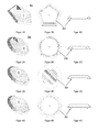
- FIG. 1, FIG. 2, FIG. 3 and FIG. 4 are inventive plastic seals 1 for sealing penetrations in sealing elements, in particular in plastic films, preferably in sub-roof sheets, shown.
- These plastic seals are made of a thermoplastic or of a thermoplastic elastomer and are produced in a so-called thermoplastic foam molding process.
- the plastic seals produced by the thermoplastic foam molding process have a foamed core and a compact outer skin.
- the foamed core gives the plastic seal the necessary elasticity, while the compact outer skin favors the drainage of the water along the plastic seal. This property can be further improved by the shape of the plastic seal. So shows, for example FIG.
- a plastic gasket 1 having a pentagonal shape which, when properly placed on an inclined plane, such as a pitched roof, favors the drainage of the water and provides no possibility for water to accumulate or accumulate at the edge of the plastic gasket and to slowly seep in to penetrate the plastic film.
- the same advantageous properties for example, also has a circular plastic seal, as in FIG. 2, FIG. 3 and FIG. 4 is shown on.
- This embodiment is in the Figures 1 and 2 shown.
- a plastic seal 1 can be produced, which has a sealing lip 2c on the underside.
- the plastic seal 1 may additionally be equipped on at least one side with a self-adhesive strip, which serves to facilitate assembly.
- a self-adhesive strip can according to FIG. 3 for example, be mounted in a recess 2b formed in the middle of the plastic seal.
- a company logo 3a or a note on the application 3b to install the plastic seal.
- these labels indicate how to optimally align the plastic gasket on an inclined plane, typically on a pitched roof.
- a company logo 3a can also serve as an assembly aid in addition to the advertising effect.
- thermoplastics and thermoplastic elastomers are in particular selected from the group consisting of polyethylene (PE), low density polyethylene (LDPE), ethylene / vinyl acetate copolymer (EVA), polybutene (PB); olefin-based thermoplastic elastomers (TPE-O, TPO) such as ethylene-propylene-diene / polypropylene copolymers; crosslinked olefin-based thermoplastic elastomers (TPE-V, TPV); thermoplastic polyurethanes (TPE-U, TPU) such as TPU with aromatic hard segments and polyester soft segments (TPU-ARES), soft polyether segments (TPU-ARET), polyester and polyether soft segments (TPU-AREE) or polycarbonate soft segments (TPU -ARCE); thermoplastic copolyesters (TPE-E, TPC) such as TPC with polyester soft segments (TPC-ES), soft polyether segments (TPC-ET) or
- thermoplastic elastomers most preferably olefin-based thermoplastic elastomers (TPE-V, TPV) and styrene block copolymers (TPE-S, TPS), in particular butylene / styrene block copolymer (TPS-SEBS).
- TPE-V olefin-based thermoplastic elastomers
- TPS styrene block copolymers
- TPS-SEBS butylene / styrene block copolymer
- thermoplastic foam casting process a blowing agent-containing injection molding compound is injected into a tool which contains the negative mold of the plastic seal according to the invention.
- the tool is only partially filled with injection molding compound, the remaining filling is carried out by the expansion of the propellant. It is distinguished between chemical and physical blowing agents.
- chemical blowing agents of the injection molding compound chemical compounds are added, which split off under the action of heat gaseous decomposition products. These liberated gases then cause the foaming, so that cell-like structures are formed in the moldings.
- the injection molding compound is injected with a gas which is inert to the polymers used, in particular nitrogen (N 2 ) or carbon dioxide (CO 2 ), in the liquid or supercritical state and mixed in.
- a gas which is inert to the polymers used, in particular nitrogen (N 2 ) or carbon dioxide (CO 2 )
- N 2 nitrogen
- CO 2 carbon dioxide
- the gas dissolves in the injection molding compound and expands only when pressure drops during the filling of the tool. This in turn results in cellular structures in the moldings. Moldings produced by this physical foaming feature a very fine, homogeneous cell structure, a compact outer skin and a low density.
- Preferred blowing agents are N 2 and CO 2 , most preferably liquid or supercritical CO 2 .
- thermoplastic foam molding process is generally known to the person skilled in the art from other fields of application and is described, for example, in US Pat Schwarz, O., Ebeling, F.-W., Furth, B., plastics processing, (Vogel book publishing, 10th edition, 2005) on pages 129-132 . Due to the thermoplastic foam casting process, plastic parts for sealing penetrations in sealing elements can be produced with optimal material use, which can be reversibly deformed due to the fine and uniform cell structure even at high temperatures and high pressure, as can occur, for example, on construction sites. In addition, the plastic gaskets produced in this way can be given a three-dimensional structure, by means of which water repellency or water removal is particularly favored.
- FIGS. 5 and 6 is a preferred application of the inventive plastic seals shown.
- an underlay 9 is mounted, whereupon a sub-roof sheet 8 comes to rest.
- plastic seals 1 according to the invention are placed at the locations where the counter-battens are fastened to the sub-roof construction with fastening means 7, typically with nails or screws, which prevent the penetration of water through the sub-roof track.
- fastening means 7 typically with nails or screws, which prevent the penetration of water through the sub-roof track.
- cover 4 such as roof tiles, laid.
- the invention comprises the use of previously described plastic seals 1 for sealing penetrations in sealing elements, in particular in plastic films, preferably in sub-roof sheets, as for example in FIG. 5 and FIG. 6 is shown.
- the plastic seals between the counter battens 6 and the sub-roof track 8 are used at those locations where the counter battens with the sub-roof construction are fastened by fastening means 7 such as nails or screws.
- plastic gaskets for example, the sealing of penetrations in objects which perform the function of a sealing element.
- these are plates and sheets of different materials such as glass, ceramic, natural stone, metals, plastic, concrete, mortar, brick, brick or wood, which may also be coated, painted or otherwise pretreated.
- plastic gaskets for roof construction these areas of application are in particular in other areas of civil engineering, in the industrial production of goods such as machinery, household appliances and means of transport or in the assembly of attachments.
Landscapes
- Engineering & Computer Science (AREA)
- Architecture (AREA)
- Civil Engineering (AREA)
- Structural Engineering (AREA)
- Sealing Material Composition (AREA)
Abstract
Description
- Die Erfindung geht aus von einer Kunststoffdichtung zur Abdichtung von Durchdringungen bei Dichtungselementen, insbesondere bei Kunststofffolien, bevorzugt bei Unterdachbahnen, welche durch Befestigungsmittel wie Nägel, Schrauben und dergleichen verursacht werden, nach dem Oberbegriff des ersten Anspruchs.
Weiterhin geht die Erfindung aus von der Verwendung derartiger Kunststoffdichtungen als Abdichtungen von Durchdringungen bei Dichtungselementen, insbesondere bei Kunststofffolien, bevorzugt bei Unterdachbahnen. - Kunststoffdichtungen zur Abdichtung von Durchdringungen bei Dichtungselementen werden insbesondere als Nagel- oder Schraubendichtungen im Dachbau, bei der Befestigung der Konterlattung mit der Unterdachkonstruktion eingesetzt. Sie sollen verhindern, dass an den Stellen, wo Nägel oder Schrauben die Unterdachbahn durchdringen, Wasser, typischerweise Regenwasser, durch das Dach eindringt.
Die heute gebräuchlichen Kunststoffdichtungen, auch Nageldichtungen genannt, bestehen in den meisten Fällen aus grossformatig zu Platten geschäumtem Polyvinylchlorid (PVC), Polyethylen (PE) oder Ethylen-Propylen-Dien-Kautschuk (EPDM) und werden anschliessend aus diesen Platten ausgestanzt. Die Zellgrösse im Endprodukt richtet sich dabei nach der Rohdichte des Schaumstoffs, wobei die Zellen sehr unterschiedliche Grössen aufweisen und unregelmässig angeordnet sind.
Derartige Nageldichtungen haben den Nachteil, dass sie sich bei hoher Wärmebelastung und hohem Pressdruck irreversibel verformen. Diese Verformung hat zur Folge, dass sich die Nageldichtungen beispielsweise beim Schwinden und/oder Verdrehen der Konterlatte, verursacht durch zyklische Wechsel zwischen nass und trocken oder durch mechanische Belastungen, nicht anpassen können und die Dichtigkeit nicht mehr gewährleistet ist. Weiterhin nachteilig sind die durch das Ausstanzen der Nageldichtungen bedingten porösen bzw. teilweise offenzelligen Seitenwände, an denen das Wasser nicht optimal abfliessen kann und sich dort somit ansammelt.
Diese Eigenschaften haben zur Folge, dass Wasser durch die Durchdringung in das Bauwerk eindringt.
Zudem ist durch das gegebene Herstellverfahren die gestalterische Freiheit bei der Formgebung der Nageldichtungen sehr begrenzt. - Der Erfindung liegt die Aufgabe zugrunde, bei einer Kunststoffdichtung zur Abdichtung von Durchdringungen bei Dichtungselementen der eingangs genannten Art die Dichtigkeit gegenüber Wasser zu verbessern.
- Erfindungsgemäss wird dies durch die Merkmale des ersten Anspruches erreicht.
- Kern der Erfindung sind also Kunststoffdichtungen zur Abdichtung von Durchdringungen bei Dichtungselementen, insbesondere bei Kunststofffolien, bevorzugt bei Unterdachbahnen, welche in einem Thermoplastschaumguss-Verfahren aus Thermoplasten oder thermoplastischen Elastomeren hergestellt werden.
- Als Dichtungselement werden in diesem Dokument Gegenstände, Substrate und Konstruktionen beliebiger Form und Zusammensetzung verstanden, welche dem Zweck dienen, einen ungewollten Stoffaustausch zwischen zwei Räumen oder Bereichen zu verhindern oder zu begrenzen.
- Als thermoplastische Elastomere werden in diesem Dokument Kunststoffe verstanden, welche die mechanischen Eigenschaften von vulkanisierten Elastomeren mit der Verarbeitbarkeit von Thermoplasten vereinen. Typischerweise sind derartige thermoplastische Elastomere Block-Copolymere mit Hart- und Weichsegmenten oder so genannte Polymerlegierungen mit entsprechend thermoplastischen und elastomeren Bestandteilen.
- Die Vorteile der Erfindung sind unter anderem darin zu sehen, dass sich die Kunststoffdichtungen, bedingt durch ihr Herstellverfahren und der Materialwahl, auch bei hohen Temperaturen und hohem Druck reversibel verformen lassen. Dadurch passt sich ihre Form bei Veränderung der Belastung, insbesondere bei Abnahme des Drucks auf die Kunststoffdichtung, an ihre direkte Umgebung an und gewährleistet eine optimale Dichtigkeit.
Ebenfalls bedingt durch das Herstellverfahren, weisen die erfindungsgemässen Kunststoffdichtungen eine kompakte Aussenhaut auf, entlang welcher das Wasser leichter abfliesst. Die wasserabweisende Wirkung kann zudem noch durch eine geeignete Formteilgeometrie begünstigt werden
Die freie dreidimensionale Gestaltung der Kunststoffdichtungen erlaubt des Weiteren, diese beispielsweise mit einem Firmenlogo oder mit einem Hinweis für die Anwendung zu versehen. - Weitere Aspekte der Erfindung sind Gegenstand weiterer unabhängiger Ansprüche. Besonders bevorzugte Ausführungsformen der Erfindung sind Gegenstand der abhängigen Ansprüche.
- Im Folgenden werden anhand der Zeichnungen Ausführungsbeispiele der Erfindung näher erläutert. Gleiche Elemente sind in den verschiedenen Figuren mit den gleichen Bezugszeichen versehen.
- Es zeigen:
- Figur 1
- schematische Darstellungen einer erfindungsgemässen Kunststoffdichtung 1 in der Perspektive (1A), von der Unterseite (1B) und im Querschnitt (1C);
- Figur 2
- schematische Darstellungen einer erfindungsgemässen Kunststoffdichtung 1 in der Perspektive (2A), von der Unterseite (2B) und im Querschnitt (2C);
- Figur 3
- schematische Darstellungen einer erfindungsgemässen Kunststoffdichtung 1 in der Perspektive (3A), von der Unterseite (3B) und im Querschnitt (3C);
- Figur 4
- schematische Darstellungen einer erfindungsgemässen Kunststoffdichtung 1 in der Perspektive (4A), von der Unterseite (4B) und im Querschnitt (4C);
- Figur 5
- eine schematische Darstellung eines Ausschnitts einer Dachkonstruktion im Querschnitt;
- Figur 6
- eine schematische Darstellung eines Ausschnitts einer Dachkonstruktion in der Perspektive.
- Es sind nur die für das unmittelbare Verständnis der Erfindung wesentlichen Elemente gezeigt.
- In
Figur 1, Figur 2, Figur 3 und Figur 4 sind erfindungsgemässe Kunststoffdichtungen 1 zur Abdichtung von Durchdringungen bei Dichtungselementen, insbesondere bei Kunststofffolien, bevorzugt bei Unterdachbahnen, dargestellt. Diese Kunststoffdichtungen bestehen aus einem Thermoplast oder aus einem thermoplastischen Elastomer und werden in einem so genannten Thermoplastschaumguss-Verfahren hergestellt.
Die durch das Thermoplastschaumguss-Verfahren hergestellten Kunststoffdichtungen weisen einen geschäumten Kern und eine kompakte Aussenhaut auf. Der geschäumte Kern verleiht der Kunststoffdichtung die erforderliche Elastizität, während die kompakte Aussenhaut das Abfliessen des Wassers entlang der Kunststoffabdichtung begünstigt. Diese Eigenschaft kann weiterhin durch die Formgestaltung der Kunststoffdichtung verbessert werden. So zeigt beispielsweiseFigur 1 eine Kunststoffdichtung 1 mit einer fünfeckigen Form, welche bei korrekter Platzierung an einer schrägen Ebene, beispielsweise einem Schrägdach, das Abfliessen des Wassers begünstigt und keine Möglichkeit bietet, dass sich Wasser am Rand der Kunststoffdichtung staut bzw. ansammelt und langsam zur Durchdringung der Kunststofffolie einsickert. Die gleichen vorteilhaften Eigenschaften weist beispielsweise auch eine kreisrunde Kunststoffdichtung, wie sie inFigur 2, Figur 3 und Figur 4 dargestellt ist, auf.
Weiterhin ist durch das Thermoplastschaumguss-Verfahren die Möglichkeit gegeben, an der Unterseite der Kunststoffdichtung 1 beispielsweise eine Rinne 2a anzubringen, welche im Fall eines Eindringens des Wassers zwischen die Kunststoffdichtung und dem Dichtungselement, das Wasser aufzufangen und abzuleiten vermag. Diese Ausführungsform ist in denFiguren 1 und 2 dargestellt.
In einer weiteren Ausführungsform, welche inFigur 4 dargestellt ist, kann durch das Thermoplastschaumguss-Verfahren eine Kunststoffdichtung 1 hergestellt werden, welche an der Unterseite eine Dichtungslippe 2c aufweist. - Weiterhin kann die Kunststoffdichtung 1 zusätzlich an mindestens einer Seite mit einem Selbstklebestreifen ausgerüstet sein, welcher der erleichterten Montage dient. Ein solcher Selbstklebestreifen kann gemäss
Figur 3 beispielsweise in einer dafür geformten Einbuchtung 2b in der Mitte der Kunststoffdichtung angebracht werden. - Die durch das Herstellungsverfahren gegebene Möglichkeit der freien Formteilgestaltung erlaubt es weiterhin, beispielsweise ein Firmenlogo 3a oder ein Hinweis zur Anwendung 3b auf die Kunststoffdichtung anzubringen. Wie in
Figur 1 und 2 dargestellt, weisen diese Beschriftungen darauf hin, wie die Kunststoffdichtung auf einer schrägen Ebene, typischerweise auf einem Schrägdach, optimal ausgerichtet werden. Wie inFigur 1 dargestellt ist, kann ein Firmenlogo 3a neben dem Werbeeffekt gleichzeitig auch als Montagehilfe dienen. - Für die Herstellung erfindungsgemässer Kunststoffdichtungen bevorzugte Thermoplaste und thermoplastische Elastomere sind insbesondere ausgewählt aus der Gruppe bestehend aus Polyethylen (PE), Low Density Polyethylen (LDPE), Ethylen/Vinylacetat-Copolymer (EVA), Polybuten (PB); thermoplastische Elastomere auf Olefinbasis (TPE-O, TPO) wie Ethylen-Propylen-Dien/Polypropylen-Copolymere; vernetzte thermoplastische Elastomere auf Olefinbasis (TPE-V, TPV); thermoplastische Polyurethane (TPE-U, TPU) wie TPU mit aromatischen Hartsegmenten und Polyester-Weichsegmenten (TPU-ARES), Polyether-Weichsegmenten (TPU-ARET), Polyester- und Polyether-Weichsegmenten (TPU-AREE) oder Polycarbonat-Weichsegmenten (TPU-ARCE); thermoplastische Copolyester (TPE-E, TPC) wie TPC mit Polyester-Weichsegmenten (TPC-ES), Polyether-Weichsegmenten (TPC-ET) oder mit Polyester- und Polyether-Weichsegmenten (TPC-EE); Styrol-Block-Copolymere (TPE-S, TPS) wie Styrol/Butadien-Block-Copolymer (TPS-SBS), Styrol/Isopren-Block-Copolymer (TPS-SIS), Styrol/Ethylen-Butylen/Styrol-Block-Copolymer (TPS-SEBS), Styrol/Ethylen-Propylen/Styrol-Block-Copolymer (TPS-SEPS); und thermoplastische Copolyamide (TPE-A, TPA). Bevorzugt werden thermoplastische Elastomere, meist bevorzugt werden thermoplastische Elastomere auf Olefinbasis (TPE-V, TPV) und Styrol-Block-Copolymere (TPE-S, TPS), insbesondere Butylen/Styrol-Block-Copolymer (TPS-SEBS).
- Im Thermoplastschaumguss-Verfahren wird eine treibmittelhaltige Spritzgussmasse in ein Werkzeug eingespritzt, welches die Negativform der erfindungsgemässen Kunststoffdichtung enthält. Das Werkzeug wird dabei nur teilweise mit Spritzgussmasse gefüllt, die Restfüllung erfolgt durch die Expansion des Treibmittels. Es wird dabei zwischen chemischen und physikalischen Treibmitteln unterschieden. Beim Thermoplastschaumguss-Verfahren mit chemischen Treibmitteln werden der Spritzgussmasse chemische Verbindungen beigemischt, welche unter Wärmeeinwirkung gasförmige Zersetzungsprodukte abspalten. Diese freiwerdenden Gase bewirken dann die Schäumung, so dass zellartige Strukturen in den Formteilen entstehen.
Beim Thermoplastschaumguss-Verfahren mit physikalischen Treibmitteln wird der Spritzgussmasse ein gegenüber den verwendeten Polymeren inertes Gas, insbesondere Stickstoff (N2) oder Kohlendioxid (CO2), im flüssigen oder überkritischen Zustand injiziert und eingemischt. Dadurch, dass die Spritzgussmasse unter Druck gehalten wird, löst sich das Gas in der Spritzgussmasse und expandiert erst bei Druckabfall während des Füllens des Werkzeugs. Somit entstehen wiederum zellartige Strukturen in den Formteilen. Durch dieses physikalische Schäumen hergestellte Formteile zeichnen sich durch eine sehr feine, homogene Zellstruktur, eine kompakte Aussenhaut und eine niedrige Dichte aus. Für die Herstellung der erfindungsgemässen Kunststoffdichtungen eignet sich insbesondere das Thermoplastschaumguss-Verfahren mit physikalischen Treibmitteln, das heisst mit Gasen. Bevorzugte Treibmittel sind N2 und CO2, meist bevorzugt ist flüssiges oder überkritisches CO2. - Das Thermoplastschaumguss-Verfahren ist dem Fachmann aus anderen Anwendungsgebieten allgemein bekannt und ist beispielsweise beschrieben in Schwarz, O., Ebeling, F.-W., Furth, B., Kunststoffverarbeitung, (Vogel Buchverlag, 10. Auflage, 2005) auf den Seiten 129 - 132.
Durch das Thermoplastschaumguss-Verfahren lassen sich bei optimalem Materialeinsatz Kunststoffteile zur Abdichtung von Durchdringungen bei Dichtungselementen herstellen, welche sich aufgrund der feinen und gleichmässigen Zellstruktur auch bei hohen Temperaturen und hohem Druck, wie sie beispielsweise auf Baustellen auftreten können, reversibel verformen lassen. Zudem kann den so hergestellten Kunststoffdichtungen eine dreidimensionale Struktur gegeben werden, durch die die Wasserabweisung bzw. die Wasserabführung besonders begünstigt wird. - In den
Figuren 5 und 6 ist ein bevorzugtes Anwendungsgebiet der erfindungsgemässen Kunststoffdichtungen dargestellt.
Auf den Dachbalken 10 ist eine Verlegeunterlage 9 angebracht, worauf dann eine Unterdachbahn 8 zu liegen kommt. Zwischen dieser Unterdachbahn und der Konterlattung 6 werden an den Stellen, an denen die Konterlattung mit Befestigungsmitteln 7, typischerweise mit Nägeln oder Schrauben, an der Unterdachkonstruktion befestigt ist, erfindungsgemässe Kunststoffdichtungen 1 platziert, welche das Eindringen von Wasser durch die Unterdachbahn verhindern. Auf die Konterlattung 6 wird eine weitere Lattung 5 angebracht, auf welcher dann die Deckung 4, beispielsweise Dachziegel, verlegt wird. - Weiterhin umfasst die Erfindung die Verwendung vorhergehend beschriebener Kunststoffdichtungen 1 zur Abdichtung von Durchdringungen bei Dichtungselementen, insbesondere bei Kunststofffolien, bevorzugt bei Unterdachbahnen, wie sie beispielsweise in
Figur 5 und Figur 6 dargestellt ist. Wie bereits beschrieben werden dabei die Kunststoffdichtungen zwischen der Konterlattung 6 und der Unterdachbahn 8 an jenen Stellen eingesetzt, an denen die Konterlatten mit der Unterdachkonstruktion durch Befestigungsmittel 7 wie Nägel oder Schrauben befestigt sind. - Selbstverständlich ist die Erfindung nicht auf das gezeigte und beschriebene Ausführungsbeispiel beschränkt.
- Weitere Anwendungsgebiete erfindungsgemässer Kunststoffdichtungen liegen beispielsweise in der Abdichtung von Durchdringungen bei Gegenständen, welche die Funktion eines Dichtungselements ausüben. Typischerweise sind dies Platten und Folien, aus unterschiedlichen Materialien wie Glas, Keramik, Naturstein, Metalle, Kunststoff, Beton, Mörtel, Backstein, Ziegel oder Holz, wobei diese auch beschichtet, lackiert oder anderweitig vorbehandelt sein können. Neben der Verwendung erfindungsgemässer Kunststoffdichtungen für den Dachbau, liegen diese Anwendungsgebiete insbesondere auch in anderen Bereichen des Hoch- und Tiefbaus, in der industriellen Fertigung von Gütern wie beispielsweise Maschinen, Haushaltsgeräten und Transportmitteln oder in der Montage von Anbauteilen.
-
- 1
- Kunststoffdichtung
- 2a
- Rinne
- 2b
- Einbuchtung
- 2c
- Dichtungslippe
- 3a
- Firmenlogo
- 3b
- Anwendungshinweis
- 4
- Deckung
- 5
- Lattung
- 6
- Konterlattung
- 7
- Befestigungsmittel
- 8
- Unterdachbahn
- 9
- Verlegeunterlage
- 10
- Dachbalken
Claims (11)
- Kunststoffdichtung (1) zur Abdichtung von Durchdringungen bei Dichtungselementen,
dadurch gekennzeichnet,
dass die Kunststoffdichtung in einem Thermoplastschaumguss-Verfahren aus Thermoplasten oder thermoplastischen Elastomeren hergestellt wird. - Kunststoffdichtung nach Anspruch 1,
dadurch gekennzeichnet,
dass im Thermoplastschaumguss-Verfahren mindestens ein physikalisches Treibmittel eingesetzt wird. - Kunststoffdichtung nach Anspruch 2,
dadurch gekennzeichnet,
dass das physikalische Treibmittel ein Gas, insbesondere N2 oder CO2, ist. - Kunststoffdichtung nach einem der vorhergehenden Ansprüche, dadurch gekennzeichnet,
dass der Thermoplast oder das thermoplastische Elastomer ausgewählt ist aus der Gruppe bestehend aus
Polyethylen (PE), Low Density Polyethylen (LDPE), Ethylen/Vinylacetat-Copolymer (EVA), Polybuten (PB);
thermoplastische Elastomere auf Olefinbasis (TPE-O, TPO) wie Ethylen-Propylen-Dien/Polypropylen-Copolymere;
vernetzte thermoplastische Elastomere auf Olefinbasis (TPE-V, TPV);
thermoplastische Polyurethane (TPE-U, TPU) wie TPU mit aromatischen Hartsegmenten und Polyester-Weichsegmenten (TPU-ARES), Polyether-Weichsegmenten (TPU-ARET), Polyester- und
Polyether-Weichsegmenten (TPU-AREE) oder Polycarbonat-Weichsegmenten (TPU-ARCE);
thermoplastische Copolyester (TPE-E, TPC) wie TPC mit Polyester-Weichsegmenten (TPC-ES), Polyether-Weichsegmenten (TPC-ET) oder mit Polyester- und Polyether-Weichsegmenten (TPC-EE);
Styrol-Block-Copolymere (TPE-S, TPS) wie Styrol/Butadien-Block-Copolymer (TPS-SBS), Styrol/Isopren-Block-Copolymer (TPS-SIS), Styrol/Ethylen-Butylen/Styrol-Block-Copolymer (TPS-SEBS), Styrol/Ethylen-Propylen/Styrol-Block-Copolymer (TPS-SEPS);
und thermoplastische Copolyamide (TPE-A, TPA). - Kunststoffdichtung nach einem der vorhergehenden Ansprüche,
dadurch gekennzeichnet,
dass sie mindestens einseitig einen Selbstklebestreifen aufweist. - Kunststoffdichtung nach einem der vorhergehenden Ansprüche,
dadurch gekennzeichnet,
dass sie mindestens einseitig eine Einbuchtung (2b) zur Anbringung eines Selbstklebestreifens aufweist. - Kunststoffdichtung nach einem der vorhergehenden Ansprüche,
dadurch gekennzeichnet,
dass sie mindestens einseitig eine Rinne (2a) zum Auffangen und Ableiten von Wasser oder eine Dichtungslippe (2c) aufweist. - Kunststoffdichtung nach einem der vorhergehenden Ansprüche,
dadurch gekennzeichnet,
dass sie für die Abdichtung von Durchdringungen bei Kunststofffolien, insbesondere bei Unterdachbahnen, verwendet wird. - Verwendung einer Kunststoffdichtung nach einem der Ansprüche 1 bis 8 als Abdichtung von Durchdringungen bei Dichtungselementen, insbesondere bei Kunststofffolien, bevorzugt bei Unterdachbahnen.
- Verwendung nach Anspruch 9,
dadurch gekennzeichnet,
dass die Kunststoffdichtung zwischen der Konterlattung (6) und der Unterdachbahn (8) an jenen Stellen eingesetzt wird, an denen die Konterlattung (6) mit der Unterdachkonstruktion mittels Befestigungsmittel (7) befestigt ist. - Verwendung nach Anspruch 10,
dadurch gekennzeichnet,
dass die Befestigungsmittel (7) Nägel oder Schrauben sind.
Priority Applications (1)
| Application Number | Priority Date | Filing Date | Title |
|---|---|---|---|
| EP07108159A EP1992761A1 (de) | 2007-05-14 | 2007-05-14 | Kunststoffdichtung im Thermoplastschaumguss-Verfahren |
Applications Claiming Priority (1)
| Application Number | Priority Date | Filing Date | Title |
|---|---|---|---|
| EP07108159A EP1992761A1 (de) | 2007-05-14 | 2007-05-14 | Kunststoffdichtung im Thermoplastschaumguss-Verfahren |
Publications (1)
| Publication Number | Publication Date |
|---|---|
| EP1992761A1 true EP1992761A1 (de) | 2008-11-19 |
Family
ID=38626827
Family Applications (1)
| Application Number | Title | Priority Date | Filing Date |
|---|---|---|---|
| EP07108159A Withdrawn EP1992761A1 (de) | 2007-05-14 | 2007-05-14 | Kunststoffdichtung im Thermoplastschaumguss-Verfahren |
Country Status (1)
| Country | Link |
|---|---|
| EP (1) | EP1992761A1 (de) |
Cited By (3)
| Publication number | Priority date | Publication date | Assignee | Title |
|---|---|---|---|---|
| DE102013202626A1 (de) | 2013-02-19 | 2014-08-21 | Lisa Dräxlmaier GmbH | Verfahren zur Herstellung eines Spritzgussteils |
| EP3712343A1 (de) | 2019-03-18 | 2020-09-23 | Lenzing Plastics GmbH & Co KG | Dichtbahn |
| DE102023107252A1 (de) * | 2023-03-22 | 2024-09-26 | Andreas Kohler | Dichtungselement, Montagesystem und Verwendung eines solchen |
Citations (7)
| Publication number | Priority date | Publication date | Assignee | Title |
|---|---|---|---|---|
| US3962016A (en) * | 1973-09-14 | 1976-06-08 | Dynamit Nobel Aktiengesellschaft | Process for joining abutting thermoplastic synthetic-resin foam sheets |
| FR2520787A1 (fr) * | 1982-02-04 | 1983-08-05 | Nord Comptoir Tuilier | Dispositif ameliorant la ventilation sous toiture et toitures munies de ce dispositif |
| FR2627428A1 (fr) * | 1988-02-19 | 1989-08-25 | Ta Trimph Adler Ag | Procede de fabrication d'un cylindre d'impression en plastique pour machines a ecrire et analogues et cylindre ainsi obtenu |
| EP0877127A1 (de) * | 1997-05-09 | 1998-11-11 | Reinhard Casutt | Verfahren zur Herstellung einer Verbindung zwischen der Dachhaut und Tragkonstruktion durch eine Wärmedämmung hindurch, Kernbohrer, Werkzeugsatz und Warmdach |
| US20010003625A1 (en) * | 1998-11-20 | 2001-06-14 | Jonathan W. Apgar | Heat weldable epdm roffing membrane |
| WO2003033232A1 (de) * | 2001-10-15 | 2003-04-24 | Peguform Gmbh & Co. Kg | Vorrichtung zur herstellung geschäumter kunststoff-formteile im spritzgiessprozess unter verwendung komprimierter physikalischer treibfluide |
| US6607793B2 (en) * | 1999-03-26 | 2003-08-19 | Omnova Solutions Inc. | Large width heat-weldable roof membrane |
-
2007
- 2007-05-14 EP EP07108159A patent/EP1992761A1/de not_active Withdrawn
Patent Citations (7)
| Publication number | Priority date | Publication date | Assignee | Title |
|---|---|---|---|---|
| US3962016A (en) * | 1973-09-14 | 1976-06-08 | Dynamit Nobel Aktiengesellschaft | Process for joining abutting thermoplastic synthetic-resin foam sheets |
| FR2520787A1 (fr) * | 1982-02-04 | 1983-08-05 | Nord Comptoir Tuilier | Dispositif ameliorant la ventilation sous toiture et toitures munies de ce dispositif |
| FR2627428A1 (fr) * | 1988-02-19 | 1989-08-25 | Ta Trimph Adler Ag | Procede de fabrication d'un cylindre d'impression en plastique pour machines a ecrire et analogues et cylindre ainsi obtenu |
| EP0877127A1 (de) * | 1997-05-09 | 1998-11-11 | Reinhard Casutt | Verfahren zur Herstellung einer Verbindung zwischen der Dachhaut und Tragkonstruktion durch eine Wärmedämmung hindurch, Kernbohrer, Werkzeugsatz und Warmdach |
| US20010003625A1 (en) * | 1998-11-20 | 2001-06-14 | Jonathan W. Apgar | Heat weldable epdm roffing membrane |
| US6607793B2 (en) * | 1999-03-26 | 2003-08-19 | Omnova Solutions Inc. | Large width heat-weldable roof membrane |
| WO2003033232A1 (de) * | 2001-10-15 | 2003-04-24 | Peguform Gmbh & Co. Kg | Vorrichtung zur herstellung geschäumter kunststoff-formteile im spritzgiessprozess unter verwendung komprimierter physikalischer treibfluide |
Cited By (3)
| Publication number | Priority date | Publication date | Assignee | Title |
|---|---|---|---|---|
| DE102013202626A1 (de) | 2013-02-19 | 2014-08-21 | Lisa Dräxlmaier GmbH | Verfahren zur Herstellung eines Spritzgussteils |
| EP3712343A1 (de) | 2019-03-18 | 2020-09-23 | Lenzing Plastics GmbH & Co KG | Dichtbahn |
| DE102023107252A1 (de) * | 2023-03-22 | 2024-09-26 | Andreas Kohler | Dichtungselement, Montagesystem und Verwendung eines solchen |
Similar Documents
| Publication | Publication Date | Title |
|---|---|---|
| EP2349707B1 (de) | Wasserdichte membran | |
| DE60116532T2 (de) | Fugendichtung mit elastischer Kappe | |
| EP3428357B1 (de) | Dehnungsfugenband und kompressionsbandanordnung zur dauerhaften zuverlässigen fugenabdichtung | |
| EP3670751B1 (de) | Dauerhaft hoch belastbare fugenabdichtungsvorrichtung | |
| EP2299005A1 (de) | Wasserdichte Membran | |
| DE102010018810B4 (de) | Bahn, insbesondere zur Verwendung im Baubereich | |
| DE202011000594U1 (de) | Auflager, insbesondere für zwei zueinander positionierbare Bauteile | |
| DE102008034347B4 (de) | Dichtungsprofilband, insbesondere Fassadendichtungsband | |
| EP1992761A1 (de) | Kunststoffdichtung im Thermoplastschaumguss-Verfahren | |
| EP3751068B1 (de) | Dehnungsfugenband zur aktiven, selbsttätigen, dauerhaften abdichtung von fugen zwischen bauwerksteilen | |
| EP1566264B1 (de) | Wärmedämmkörper | |
| EP4397820B1 (de) | Anschlusseinheit für eine dachentwässerung mit einem anschlussrahmen | |
| DE19719474A1 (de) | Strangdichtung | |
| EP0877143B1 (de) | Strangdichtung | |
| WO2008122065A1 (de) | Belagsmaterial zur direkten anbindung an ein betonbauteil | |
| DE4414211A1 (de) | Lüfterkappe und Verbindungselement zum Verbinden eines Schaumstoffelementes mit dem Trägerelement einer derartigen Lüfterkappe | |
| DE19529545A1 (de) | Vorrichtung zur Abdichtung eines Wassereinlaufes | |
| EP2625219B1 (de) | Dichtungs- oder dämpfungsprofil | |
| EP1983120B1 (de) | Fugenabdichtungselement | |
| DE20319727U1 (de) | Dichtungsprofil mit hoher Dichtwirkung, ausgezeichneter Vibrationsdämpfung und ausdauernder mechanischer Belastbarkeit | |
| DE20117679U1 (de) | Abdichtungsprofilstrang für die dauerhafte Abdichtung zwischen zwei Bauteilen | |
| DE102005017921A1 (de) | Bausatz für die lineare meachanische Befestigung von Dämmmaterialien und Abdichtungsbahnen auf Flachdächern | |
| EP3115539B1 (de) | Bauwerksbereich mit dichtband | |
| DE202005006231U1 (de) | Bausatz für die lineare mechanische Befestigung von Dämmmaterialien und Abdichtungsbahnen auf Flachdächern | |
| WO2012143034A1 (de) | Dach-abdichtung |
Legal Events
| Date | Code | Title | Description |
|---|---|---|---|
| PUAI | Public reference made under article 153(3) epc to a published international application that has entered the european phase |
Free format text: ORIGINAL CODE: 0009012 |
|
| AK | Designated contracting states |
Kind code of ref document: A1 Designated state(s): AT BE BG CH CY CZ DE DK EE ES FI FR GB GR HU IE IS IT LI LT LU LV MC MT NL PL PT RO SE SI SK TR |
|
| AX | Request for extension of the european patent |
Extension state: AL BA HR MK RS |
|
| 17P | Request for examination filed |
Effective date: 20090519 |
|
| AKX | Designation fees paid |
Designated state(s): AT BE BG CH CY CZ DE DK EE ES FI FR GB GR HU IE IS IT LI LT LU LV MC MT NL PL PT RO SE SI SK TR |
|
| 17Q | First examination report despatched |
Effective date: 20090707 |
|
| STAA | Information on the status of an ep patent application or granted ep patent |
Free format text: STATUS: THE APPLICATION IS DEEMED TO BE WITHDRAWN |
|
| 18D | Application deemed to be withdrawn |
Effective date: 20100119 |