EP1992017B1 - Dispositif de fixation d'objets sur des surfaces extérieures étanchées d'immeubles - Google Patents
Dispositif de fixation d'objets sur des surfaces extérieures étanchées d'immeubles Download PDFInfo
- Publication number
- EP1992017B1 EP1992017B1 EP07722829.4A EP07722829A EP1992017B1 EP 1992017 B1 EP1992017 B1 EP 1992017B1 EP 07722829 A EP07722829 A EP 07722829A EP 1992017 B1 EP1992017 B1 EP 1992017B1
- Authority
- EP
- European Patent Office
- Prior art keywords
- fastening device
- mounting body
- seal
- section
- projecting section
- Prior art date
- Legal status (The legal status is an assumption and is not a legal conclusion. Google has not performed a legal analysis and makes no representation as to the accuracy of the status listed.)
- Active
Links
- 238000007789 sealing Methods 0.000 claims description 71
- 239000000463 material Substances 0.000 claims description 29
- 239000010410 layer Substances 0.000 claims description 28
- 238000010276 construction Methods 0.000 claims description 21
- 230000004888 barrier function Effects 0.000 claims description 10
- 229920003023 plastic Polymers 0.000 claims description 8
- 239000004033 plastic Substances 0.000 claims description 8
- 229920001084 poly(chloroprene) Polymers 0.000 claims description 7
- 239000002356 single layer Substances 0.000 claims description 2
- 239000010426 asphalt Substances 0.000 claims 1
- 238000009413 insulation Methods 0.000 description 20
- 238000000576 coating method Methods 0.000 description 8
- 238000003466 welding Methods 0.000 description 8
- XLYOFNOQVPJJNP-UHFFFAOYSA-N water Substances O XLYOFNOQVPJJNP-UHFFFAOYSA-N 0.000 description 7
- 239000007787 solid Substances 0.000 description 6
- 239000013589 supplement Substances 0.000 description 6
- 239000011248 coating agent Substances 0.000 description 5
- 229910000831 Steel Inorganic materials 0.000 description 4
- 239000004567 concrete Substances 0.000 description 4
- 238000005304 joining Methods 0.000 description 4
- 230000013011 mating Effects 0.000 description 4
- 239000010959 steel Substances 0.000 description 4
- 238000005553 drilling Methods 0.000 description 3
- 239000002184 metal Substances 0.000 description 3
- 238000000034 method Methods 0.000 description 3
- 230000035515 penetration Effects 0.000 description 3
- 239000011150 reinforced concrete Substances 0.000 description 3
- 239000002023 wood Substances 0.000 description 3
- 244000025254 Cannabis sativa Species 0.000 description 2
- 230000006978 adaptation Effects 0.000 description 2
- 230000008901 benefit Effects 0.000 description 2
- 230000007797 corrosion Effects 0.000 description 2
- 238000005260 corrosion Methods 0.000 description 2
- 230000000694 effects Effects 0.000 description 2
- 230000006698 induction Effects 0.000 description 2
- 239000011810 insulating material Substances 0.000 description 2
- 229920000728 polyester Polymers 0.000 description 2
- 229920000642 polymer Polymers 0.000 description 2
- 229920002223 polystyrene Polymers 0.000 description 2
- 229920002635 polyurethane Polymers 0.000 description 2
- 239000010935 stainless steel Substances 0.000 description 2
- 229910001220 stainless steel Inorganic materials 0.000 description 2
- 238000004078 waterproofing Methods 0.000 description 2
- 235000012766 Cannabis sativa ssp. sativa var. sativa Nutrition 0.000 description 1
- 235000012765 Cannabis sativa ssp. sativa var. spontanea Nutrition 0.000 description 1
- 229910001335 Galvanized steel Inorganic materials 0.000 description 1
- 241000208202 Linaceae Species 0.000 description 1
- 235000004431 Linum usitatissimum Nutrition 0.000 description 1
- 101100498160 Mus musculus Dach1 gene Proteins 0.000 description 1
- 239000004793 Polystyrene Substances 0.000 description 1
- 229920002522 Wood fibre Polymers 0.000 description 1
- 238000004026 adhesive bonding Methods 0.000 description 1
- 235000009120 camo Nutrition 0.000 description 1
- 229920002678 cellulose Polymers 0.000 description 1
- 239000001913 cellulose Substances 0.000 description 1
- 235000005607 chanvre indien Nutrition 0.000 description 1
- 239000002131 composite material Substances 0.000 description 1
- 238000009833 condensation Methods 0.000 description 1
- 230000005494 condensation Effects 0.000 description 1
- 239000004035 construction material Substances 0.000 description 1
- -1 etc.) Substances 0.000 description 1
- 239000011494 foam glass Substances 0.000 description 1
- 239000008397 galvanized steel Substances 0.000 description 1
- 239000011491 glass wool Substances 0.000 description 1
- 239000003292 glue Substances 0.000 description 1
- KGZJRXKGJRJKCB-UHFFFAOYSA-N hanf Chemical compound C=1C=CC=CC=1CC(C(=O)NC(CCCNC(N)=N)C(=O)NC(CC=1C=CC(O)=CC=1)C(O)=O)NC(=O)C(CO)NC(=O)C(CC(N)=O)NC(=O)C(CS)NC(=O)CNC(=O)C(CC(C)C)NC(=O)CNC(=O)C(CO)NC(=O)C(CCC(N)=O)NC(=O)C(C)NC(=O)CNC(=O)C(C(C)CC)NC(=O)C(CCCNC(N)=N)NC(=O)C(CC(O)=O)NC(=O)C(CCSC)NC(=O)C(CCCNC(N)=N)NC(=O)CNC(=O)CNC(=O)C(NC(=O)C(CS)NC(=O)C(CO)NC(=O)C(CO)NC(=O)C(CCCNC(N)=N)NC(=O)C(CCCNC(N)=N)NC(=O)C(CC(C)C)NC(=O)C(N)CO)CC1=CC=CC=C1 KGZJRXKGJRJKCB-UHFFFAOYSA-N 0.000 description 1
- 239000011487 hemp Substances 0.000 description 1
- 229910052500 inorganic mineral Inorganic materials 0.000 description 1
- 238000009434 installation Methods 0.000 description 1
- 239000012774 insulation material Substances 0.000 description 1
- 238000012423 maintenance Methods 0.000 description 1
- 238000004519 manufacturing process Methods 0.000 description 1
- 238000002844 melting Methods 0.000 description 1
- 230000008018 melting Effects 0.000 description 1
- 239000012528 membrane Substances 0.000 description 1
- 239000011707 mineral Substances 0.000 description 1
- 238000012986 modification Methods 0.000 description 1
- 230000004048 modification Effects 0.000 description 1
- 230000000149 penetrating effect Effects 0.000 description 1
- 239000002985 plastic film Substances 0.000 description 1
- 229920006255 plastic film Polymers 0.000 description 1
- 239000004814 polyurethane Substances 0.000 description 1
- 230000008569 process Effects 0.000 description 1
- 230000008439 repair process Effects 0.000 description 1
- 238000009420 retrofitting Methods 0.000 description 1
- 125000006850 spacer group Chemical group 0.000 description 1
- 230000003068 static effect Effects 0.000 description 1
- 238000003860 storage Methods 0.000 description 1
- 229920001169 thermoplastic Polymers 0.000 description 1
- 239000004416 thermosoftening plastic Substances 0.000 description 1
- 239000002025 wood fiber Substances 0.000 description 1
Images

Classifications
-
- H—ELECTRICITY
- H02—GENERATION; CONVERSION OR DISTRIBUTION OF ELECTRIC POWER
- H02S—GENERATION OF ELECTRIC POWER BY CONVERSION OF INFRARED RADIATION, VISIBLE LIGHT OR ULTRAVIOLET LIGHT, e.g. USING PHOTOVOLTAIC [PV] MODULES
- H02S20/00—Supporting structures for PV modules
- H02S20/20—Supporting structures directly fixed to an immovable object
- H02S20/22—Supporting structures directly fixed to an immovable object specially adapted for buildings
- H02S20/23—Supporting structures directly fixed to an immovable object specially adapted for buildings specially adapted for roof structures
-
- F—MECHANICAL ENGINEERING; LIGHTING; HEATING; WEAPONS; BLASTING
- F24—HEATING; RANGES; VENTILATING
- F24S—SOLAR HEAT COLLECTORS; SOLAR HEAT SYSTEMS
- F24S25/00—Arrangement of stationary mountings or supports for solar heat collector modules
- F24S25/30—Arrangement of stationary mountings or supports for solar heat collector modules using elongate rigid mounting elements extending substantially along the supporting surface, e.g. for covering buildings with solar heat collectors
-
- F—MECHANICAL ENGINEERING; LIGHTING; HEATING; WEAPONS; BLASTING
- F24—HEATING; RANGES; VENTILATING
- F24S—SOLAR HEAT COLLECTORS; SOLAR HEAT SYSTEMS
- F24S25/00—Arrangement of stationary mountings or supports for solar heat collector modules
- F24S25/60—Fixation means, e.g. fasteners, specially adapted for supporting solar heat collector modules
- F24S25/61—Fixation means, e.g. fasteners, specially adapted for supporting solar heat collector modules for fixing to the ground or to building structures
-
- F—MECHANICAL ENGINEERING; LIGHTING; HEATING; WEAPONS; BLASTING
- F24—HEATING; RANGES; VENTILATING
- F24S—SOLAR HEAT COLLECTORS; SOLAR HEAT SYSTEMS
- F24S25/00—Arrangement of stationary mountings or supports for solar heat collector modules
- F24S25/60—Fixation means, e.g. fasteners, specially adapted for supporting solar heat collector modules
- F24S25/65—Fixation means, e.g. fasteners, specially adapted for supporting solar heat collector modules for coupling adjacent supporting elements, e.g. for connecting profiles together
-
- F—MECHANICAL ENGINEERING; LIGHTING; HEATING; WEAPONS; BLASTING
- F24—HEATING; RANGES; VENTILATING
- F24S—SOLAR HEAT COLLECTORS; SOLAR HEAT SYSTEMS
- F24S25/00—Arrangement of stationary mountings or supports for solar heat collector modules
- F24S25/70—Arrangement of stationary mountings or supports for solar heat collector modules with means for adjusting the final position or orientation of supporting elements in relation to each other or to a mounting surface; with means for compensating mounting tolerances
-
- F—MECHANICAL ENGINEERING; LIGHTING; HEATING; WEAPONS; BLASTING
- F24—HEATING; RANGES; VENTILATING
- F24S—SOLAR HEAT COLLECTORS; SOLAR HEAT SYSTEMS
- F24S25/00—Arrangement of stationary mountings or supports for solar heat collector modules
- F24S2025/01—Special support components; Methods of use
- F24S2025/021—Sealing means between support elements and mounting surface
-
- F—MECHANICAL ENGINEERING; LIGHTING; HEATING; WEAPONS; BLASTING
- F24—HEATING; RANGES; VENTILATING
- F24S—SOLAR HEAT COLLECTORS; SOLAR HEAT SYSTEMS
- F24S25/00—Arrangement of stationary mountings or supports for solar heat collector modules
- F24S25/60—Fixation means, e.g. fasteners, specially adapted for supporting solar heat collector modules
- F24S2025/6006—Fixation means, e.g. fasteners, specially adapted for supporting solar heat collector modules by using threaded elements, e.g. stud bolts
-
- Y—GENERAL TAGGING OF NEW TECHNOLOGICAL DEVELOPMENTS; GENERAL TAGGING OF CROSS-SECTIONAL TECHNOLOGIES SPANNING OVER SEVERAL SECTIONS OF THE IPC; TECHNICAL SUBJECTS COVERED BY FORMER USPC CROSS-REFERENCE ART COLLECTIONS [XRACs] AND DIGESTS
- Y02—TECHNOLOGIES OR APPLICATIONS FOR MITIGATION OR ADAPTATION AGAINST CLIMATE CHANGE
- Y02B—CLIMATE CHANGE MITIGATION TECHNOLOGIES RELATED TO BUILDINGS, e.g. HOUSING, HOUSE APPLIANCES OR RELATED END-USER APPLICATIONS
- Y02B10/00—Integration of renewable energy sources in buildings
- Y02B10/10—Photovoltaic [PV]
-
- Y—GENERAL TAGGING OF NEW TECHNOLOGICAL DEVELOPMENTS; GENERAL TAGGING OF CROSS-SECTIONAL TECHNOLOGIES SPANNING OVER SEVERAL SECTIONS OF THE IPC; TECHNICAL SUBJECTS COVERED BY FORMER USPC CROSS-REFERENCE ART COLLECTIONS [XRACs] AND DIGESTS
- Y02—TECHNOLOGIES OR APPLICATIONS FOR MITIGATION OR ADAPTATION AGAINST CLIMATE CHANGE
- Y02B—CLIMATE CHANGE MITIGATION TECHNOLOGIES RELATED TO BUILDINGS, e.g. HOUSING, HOUSE APPLIANCES OR RELATED END-USER APPLICATIONS
- Y02B10/00—Integration of renewable energy sources in buildings
- Y02B10/20—Solar thermal
-
- Y—GENERAL TAGGING OF NEW TECHNOLOGICAL DEVELOPMENTS; GENERAL TAGGING OF CROSS-SECTIONAL TECHNOLOGIES SPANNING OVER SEVERAL SECTIONS OF THE IPC; TECHNICAL SUBJECTS COVERED BY FORMER USPC CROSS-REFERENCE ART COLLECTIONS [XRACs] AND DIGESTS
- Y02—TECHNOLOGIES OR APPLICATIONS FOR MITIGATION OR ADAPTATION AGAINST CLIMATE CHANGE
- Y02E—REDUCTION OF GREENHOUSE GAS [GHG] EMISSIONS, RELATED TO ENERGY GENERATION, TRANSMISSION OR DISTRIBUTION
- Y02E10/00—Energy generation through renewable energy sources
- Y02E10/40—Solar thermal energy, e.g. solar towers
- Y02E10/47—Mountings or tracking
-
- Y—GENERAL TAGGING OF NEW TECHNOLOGICAL DEVELOPMENTS; GENERAL TAGGING OF CROSS-SECTIONAL TECHNOLOGIES SPANNING OVER SEVERAL SECTIONS OF THE IPC; TECHNICAL SUBJECTS COVERED BY FORMER USPC CROSS-REFERENCE ART COLLECTIONS [XRACs] AND DIGESTS
- Y02—TECHNOLOGIES OR APPLICATIONS FOR MITIGATION OR ADAPTATION AGAINST CLIMATE CHANGE
- Y02E—REDUCTION OF GREENHOUSE GAS [GHG] EMISSIONS, RELATED TO ENERGY GENERATION, TRANSMISSION OR DISTRIBUTION
- Y02E10/00—Energy generation through renewable energy sources
- Y02E10/50—Photovoltaic [PV] energy
Definitions
- the invention relates to a fastening device for objects, in particular for structures such as photovoltaic systems, on sealed exterior building surfaces such.
- Flat roof constructions according to the preamble of claim 1.
- ballastings of the substructure known from solid flat roofs are usually unsuitable for static reasons.
- a fastening device according to the preamble of claim 1 is made FR 2 676 242 A1 known.
- a mounting unit according to the preamble of claim 11 is made US 2002/0066235 A1 known
- the invention is therefore based on the object, an attachment device for objects on sealed exterior building surfaces such. to create for flat roof structures, which ensures a flexible and sufficient attachment of objects or structures with the least possible additional burden.
- the object to be fastened is fastened directly to the roof structure via the mounting body and the fastening element, so that the object is adequately secured in the case of wind forces or the like. Due to the direct attachment to the support structure can be dispensed with an additional ballast, so that the fastening device according to the invention especially for lightweight roof constructions, but also for Solid roof structures with low reserve capacity is suitable. By bridging the force of the object directly on the roof construction, the other roof layers, such as the seal and the thermal insulation, are not further burdened. Furthermore, a secure sealing of the penetration point is ensured via the sealing collar and based on a so-called.
- a sealing collar located between the mounting body and the protruding section forms overlapping sections with the sealing of the building exterior surface or the roof and can be sealingly connected thereto.
- the fastening device according to the invention is thus not only suitable for new buildings, but can also be retrofitted without much effort on existing flat roofs by the over the support structure layer package located (insulation, sealing, etc.) is only selectively opened to the introduction of the fastener and then sealed again by means of sealing sleeve and loose and fixed flange connection between the mounting body and fastener.
- the base portion of the fastener can be mounted on hot roofs directly on the support structure located on the vapor barrier layer, so that they need not be removed for mounting the fastening device.
- the sealing collar is secured by means of a tightening means, e.g. a screw between the mounting body and projection portion pressed tight.
- a tightening means e.g. a screw between the mounting body and projection portion pressed tight.
- a tightening means e.g. a screw between the mounting body and projection portion pressed tight.
- Such an entrapment can take place on the basis of a loose and fixed flange construction according to DIN 18195 T9.
- DIN 18195 T9 This makes it easy to securely seal the connection between the mounting body and fastener.
- a simple clamping connection can be realized by a screw connection.
- it can equally apply to any other clamping connection, for example, a clamping connection with at least one clamping bolt, which is on the one hand connected to the projection portion and on the other hand cooperates with a device with which the mounting body is clamped against the projection portion.
- the clamping or screw connection is such that at least one or more clamping or threaded bolts or clamping or screw connections are mounted for attaching the mounting body either materially or such that a joining surface between the clamping bolt and the projecting portion does not pass through the projecting portion Has. This means that even with water entering between the mounting body and protrusion portion no moisture on the joining surface, such as the thread can enter through the protruding portion in the roof interior.
- the projection portion is height adjustable.
- the universal fastening device can be adapted to the respective conditions on site. An adaptation already in the production of the fastening device is thus eliminated.
- the height adjustment can be done in different ways.
- a particularly simple handling is characterized by a two-piece bolt, of which one portion has a thread which can be screwed to the mating thread of the other pin portion.
- the position of the two bolt sections relative to one another and thus the distance between the end face of the projecting section and the supporting structure can be set in a simple manner and the respective thickness of the thermal insulation and the other layers adapted.
- the fastening device can be fastened to the supporting structure in the preassembled state with the sealing collar clamped between the mounting body and the protruding section.
- a sealing or pressure supplement such as a neoprene layer or plate, may additionally be provided between the mounting body and the sealing collar and / or between the projection section and the sealing collar.
- This seal or pressure supplement for example, as a neoprene layer ensures a uniform contact pressure between the mounting body and fastener and compensates for any bumps in the sealing sleeve, so that a secure seal is guaranteed.
- a material for the seal or pressure supplement and the material of the sealing sleeve can be used. Basically, the material and / or the geometry of the seal or pressure supplement to the present Adjusted boundary conditions, such as the thickness and / or the compressibility of the clamped layer, so that a maximum and sealing effect is ensured.
- Mounting body and projection portion can not only be frictionally, e.g. connect via a screw connection with each other, but also cohesively, e.g. by suitable welding methods, in particular heat welding or induction welding, or by gluing.
- the mounting body and the protrusion portion When joined by a welding process, the mounting body and the protrusion portion have coatings at appropriate locations so that they can be welded respectively to the seal or the sealing collar and connected to each other via the seal or the sealing collar.
- appropriate materials compatible with the material of the seal or of the sealing sleeve are to be selected for the coating of the mounting body and of the protruding section.
- the height of the protrusion portion may be selected so that the end surface of the protrusion portion is flush with the seal.
- the height of the protruding portion of the fastener may preferably be selected so that it protrudes beyond the seal, so that the level of the connecting portion in the Usually located above the water-bearing layer of the roof waterproofing.
- sealing sleeve and seal both can be welded together or tightly glued.
- Such an approach has is well proven in repair work on flat roofs, especially if the material used for the sealing sleeve the same material as in the seal or at least a compatible material which can be sealingly connected to the seal.
- the material used for the sealing sleeve the same material as in the seal or at least a compatible material which can be sealingly connected to the seal.
- mono- or multilayer bituminous or plastic layers have proven to be particularly suitable.
- the mounting body and / or the fastening element is advantageously made of stainless steel, e.g. V2A produced, which in addition to a sufficient strength, a good corrosion resistance is provided.
- the fastening device according to the invention can be used for a wide variety of roof structures, in particular with trapezoidal sheet metal roofs with differently wide and / or spaced upper belts with simple assembly handling. Due to the existing hole pattern assembly is greatly simplified. Nevertheless, due to the enlarged compared to the projecting portion surface of the base portion ensured that always one or the other bore in coincidence with a top chord and with high probability even with multiple top chords of the trapezoidal sheet comes, so that a standard fastener is created, which is suitable for a variety of trapezoidal roofs suitable is.
- the attachment point pattern is no longer coupled with the geometry of the flax roof and no longer to the orientation of the flat roof construction. This is especially important for photovoltaic systems, because these then independent of the building direction can be aligned preferably to the south.
- the surface of the base portion is preferably adapted to the supporting structure of the building exterior surface or the flat roof. It may be limited in certain applications to the base of a spacer bolt, which then forms the projection portion at the same time.
- the cavity formed by or bridged by the projecting portion can be insulated with insulating material, e.g. with the insulating material that has been removed before the introduction of the fastener from the roof, filled.
- fastening device can be used in conjunction with all common supporting structures, such as concrete, steel, wood, Trapezblechblechkonstrutationen and others, so that it is a very flexible usable device.
- the fixation of the position of the two bolt sections to one another can preferably take place via a lock nut.
- an insulating section can preferably be arranged between the base section and the supporting structure, which thermally decouples the fastening device from the supporting structure of the building exterior surface, so that no heat or cold is conducted via the fastening device into the building interior.
- the storage can be kept simple even when fastening devices for a variety of roof structures, especially different thicknesses to be provided in a very short time, the core of the fastening device is combined to form a mounting unit, which is the subject of the independent claims.
- This mounting unit is pre-assembled in such a way that the sealing collar with a predetermined blank is already firmly clamped and sealed all around.
- the mounting plates can be uniformly formed for all applications, so that only the web parts must be kept variable. The web parts are therefore vorzuhalten in different lengths.
- the web parts can also be pre-assembled with either the support plate or with the mounting plate to a manageable unit.
- the clamping or clamping force of the at least one clamping bolt can be introduced to the sealing sleeve on at least one side via a sealing shim.
- the web portion may be formed by a threaded rod or tube, in which case the support plate carries either a screw nut or a threaded bolt on the underside.
- the assembly unit which can be handled as a unit can also be expanded by the web part and even by the mounting plate.
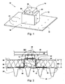
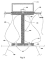
- Fig. 1 shows a perspective view of the fastening device 10 with a fastening element 12 and a mounting body 14.
- the fastening element 12 has a base portion 16 and a projection portion 18. How out Fig. 1 it can also be seen, the projection portion 18 is centered on the base portion 16 is arranged. However, the fastener 12 may have not only one but also a plurality of distributed protrusion portions 18 of the same height.
- the projection portion 18 is cuboid or cube-shaped, is secured to the end face 20 by means of clamping or threaded bolt 22 or a normal screw the mounting body 14.
- the projection portion may also be designed differently and, for example, have the shape of a cylinder, cone or truncated pyramid.
- the mounting body 14 is formed by an open, extruded or otherwise manufactured box profile having on the end face 20 of the protruding portion 18 side facing holes 24 for the clamping or threaded bolt 22 and on the opposite side has holes 26 for fixing an object.
- This article may be, for example, a substructure for photovoltaic systems, elevated maintenance route or escape route constructions, lightning protection or antenna devices, and the like.
- the base portion 16 of the fastener 12 is attached to the upper straps 30 and over the vapor barrier 34 with fasteners 40, such as tilting dowels or the like.
- the height H of the protrusion portion 18 is set to be greater than the height WD of the thermal insulation 36 and the comparatively thin seal 38 together, so that the end surface 20 of the protrusion portion 18 protrudes beyond the seal 38.
- a sealing collar 42 is disposed so as to form overlapping portions 44 with the surrounding seal 38 of the roof. At the overlapping portions 44, the sealing collar 42 is sealed to the seal 38, eg, by welding or Sealing, sealingly connected.
- the same material as in the seal 38 for example, a two-layered bituminous or a single-layer plastic layer can be used.
- a neoprene plate 46, plastic plate or the like can be arranged, which is sealingly clamped together with the sealing sleeve by the mounting body 14 fastened above.
- recesses for the screw connection between mounting body 14 and fastening element 12 are provided in the sealing collar 42 and in the neoprene plate 46.
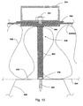
- the fastening device is not subsequently mounted on an already flat roof, but is taken into account in the new building, it is possible to attach the fastener 12 to the support structure 28 before the insulation 36 and the seal 38 are laid on the flat roof. Since in this case the seal 38 does not first have to be opened and then sealed again by means of the sealing collar 42, the newly laid seal 38 itself can be clamped between the mounting body 14 and the projection section 18.
- the construction is like in Fig. 2 shown, except that just instead of the sealing collar 42, the seal 38 is clamped continuously between the mounting body 14 and projection portion 18 of the fastener 12.
- one or more clamping or threaded bolts 22 protrude from the end face 20, which are carried out from the inside by recesses in the end face wall of the protruding section 18 and are subsequently welded to the protruding section (see FIG Fig. 3 ). In this way, it is ensured that no moisture can penetrate into the interior of the fastening element 12 and into the interior of the building via the threaded screw connections.
- the object to be fastened for example the base support 48 of a photovoltaic system, is fastened to the mounting body 14 with any fastening element 50.
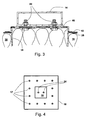
- Fig. 4 In the plan view of Fig. 4 are clearly the preferably prefabricated holes 17 in the base portion and the holes 24 in the projection portion 18 can be seen.
- more holes 17 are provided in the base portion than they would be necessary for attachment to the roof structure, eg on a concrete floor or in the embodiment shown here on the trapezoidal sheet 28.
- a rectangular base whose one side length is at least 400mm for the base portion and 200x200mm for the end face 20 of the projecting portion 18 have been found to be practicable dimensions.
- the subject invention is not limited to these dimensions.
- the fastener 10 i. the fastener 12 and the mounting body 14, made of stainless steel, e.g. made of V2A, galvanized steel or composite construction materials.
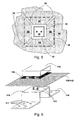
- the fastening device 10 can not only be installed in new roof roofs, but also subsequently in existing flat roofs.
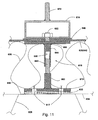
- Fig. 5 When retrofitting is how out Fig. 5 It can be seen, cut out of the seal 38 and the thermal insulation material 36 in about the size of the protruding portion 18 or removed.
- sealing 38 and thermal insulation 36 are slit in such a way that the slots 52 correspond approximately to the diagonal of the rectangular base of the base portion 16.
- These slots 52 are sufficient to be able to fold up the four formed by the slots 52 trapezoidal portions 54 of the seal 38 and insulation 36 so that the fastener 12 is introduced with the base portion 16 ahead under the seal 38 and insulation 36 and secured to the trapezoidal sheet 28 can be.
- subsequently introduced into the seal 38 slots 52 for example with the aid of Abdichtbahnen 56 or one of the slots 52 overlapping sealing collar 42, are sealed again.
- FIGS. 6 to 10 Further embodiments of the fastening device and the fastener are shown. To simplify the description, those components that correspond to the components of the previously described embodiment are given identical or similar reference numerals, preceded by another digit.
- Fig. 6 shows a configured as an angle profile fastener 112.
- the base portions 116 are provided with a hole pattern.
- fastener 212 shown is formed from a sheet to a rectangular hollow profile, one (lower) side of the base portion 216 and the other three sides of the projecting portion 218 form.
- the fastening element formed in this way can, for example, be materially connected, preferably welded, to the abutting edges.
- the projection portions 318 are modified. They are formed by a plurality of bolts 362 which are fixed to a base plate 366 and the upper side carrying a plate, which in turn - as in the embodiment of the FIGS. 1 to 5 - Is connected to the clamping or threaded bolts 322 material fit.
- the base surface of the base portion 16, 216, 316 is preferably chosen so that it covers a sufficiently large area with the hole pattern 17, 117, 317, so that a sufficient number of holes 17, 117, 317 lie over bearing areas of the supporting structure of the sealed exterior building surface come.
- the footprint can also be reduced, which is based on the following embodiments according to the Figures 9 and 10 should be explained. These figures represent almost true to scale cuts of fasteners.
- the base portion 416 a surface much smaller plate - for example, with an edge dimension of about 100 x 100 mm - which is equipped with a plurality of holes 417 and a stud 462 (for example, bar steel with a diameter of 15 to 20 mm) contributes or with this is welded.
- the stud bolt 462 passes over a shoulder into a clamping or threaded section 422.
- a support plate 466 On the shoulder is a support plate 466, which may be about the same size as the base plate 416 and against - as in connection with the FIGS. 1 to 5 described over the plate 446 and the seal 438, 442 of the mounting body 414 is tensioned.
- the bridged by the stud bolts 462 space is in turn filled by a thermal insulation 436.
- the fastening device 410 and the supporting structure 428 of the building exterior surface may additionally between the base portion 416 and the support structure 428, preferably between the base portion 416 and the vapor barrier 434, an insulating portion 433 of a material with the lowest possible thermal conductivity, for. made of hard plastic or other suitable materials.
- the insulating portion 433 may advantageously consist of the material of the roof skin. In this case, in retrofitted fastening devices previously removed from the roof skin piece of roofing can be used.
- the variant can FIG. 10 be used.
- the base surface of the base portion 516 is reduced here to the cross-sectional area of the stud bolt 562, which is anchored by means of a recessed drill screw 560 on the support structure 528, where there is a sufficiently high stability.
- this embodiment corresponds to the variant of FIG. 9 ,
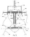
- FIG. 11 shows a variant of the embodiment according to the invention FIG. 9 which provides a length-adjustable projection portion 618.
- This height adjustment of the projecting portion 618 allows the universal use of the fastening device 10 according to the invention for different thickness layer packages (thermal insulation, sealing, vapor barrier, etc.) on the building exterior surfaces.
- the Length or height adjustment of the projection portion 618 may, for example - as in FIG. 11 shown by a two-part stud 662, 664, the lower bolt portion 662 is connected to the base portion 616 and the upper bolt portion 664 carries a support plate 666, which in turn - as in the embodiment of the FIGS. 1 to 10 - With the / n clamping or threaded bolt 622 is materially connected.
- the relative position of the two bolt portions 662 and 664 and thus the relative position of the base portion 612 and the support plate 666 can be set and fixed via a thread 663 of the one bolt portion 622 and a mating thread 665 of the other bolt portion 664.
- FIG. 12 Another embodiment of a height-adjustable projection portion 718 is shown in FIG. 12 shown.
- the lower pin portion 762 forms a threaded rod 763 which can be screwed into a sleeve 764 with a mating thread 765 which forms the upper pin portion and carries a support plate 766.
- support plate 766 may be provided with stiffening ribs 767.
- the one of the bolt portions 762; 764 bridged space is again filled by a thermal insulation 736.
- one or more clamping or threaded bolts 722 protrude from the support plate 766, which are carried out from the inside by recesses in the support plate 766 of the projection section 718 and subsequently welded to the support plate 766. In this way, it is ensured that no moisture can penetrate into the interior of the fastening element 712 and into the interior of the building via the threaded screw connections.
- recesses 774 at appropriate locations in the mounting body be provided. Via a lock nut 770, the distance between the two bolt sections and thus the distance between the end face 720 of the projection section 718 and the base section 716 can be adjusted and fixed.
- the threaded bolts 822 are welded to the upper side of the support plate 866, wherein in each case additionally a screw lock 823 is used.
- the support plate 866 On the underside, the support plate 866 carries a fitting, namely a nut 864, for a web portion in the form of a threaded rod 863.
- the base portion 816, i. the mounting plate carries on top also a screw nut 862 for the engagement of the threaded rod 863.
- the gasket 846 on the top and on the bottom of a further gasket 847 is provided.
- Neoprene can again serve as the material for the gasket or pressure supplement, but the material of the sealing gasket can also be used. Basically, the material and / or the geometry of the seal or pressure supplement to the present Adjusted boundary conditions, such as the thickness and / or the compressibility of the clamped layer, so that a maximum and sealing effect is ensured.
- a mounting unit that can be kept in stock for a variety of applications in pre-assembled state.
- the clamping plate 822 is connected to the support plate either materially or in such a way that a joining surface between the clamping bolt and the clamping plate has no passage through the support plate.
- the superstructure body 814 designated 814 is tensioned against the support plate 866 by means of the at least one clamping bolt 822, with the interposition of the sealing sleeve 842 projecting on all sides of the support plate.
- the decisive for the sealing components are therefore already pre-assembled, so that on the site only the roof skin must be cut, the units A, B and C used and the sealing sleeve 842 with the roof skin circumferentially tightly connected, preferably welded or glued, whereby a perfect sealing of the roof can be ensured after the sealing of the sealing collar 842 with the rest of the roof skin, as described with reference to the embodiments of FIGS. 1 to 12 is described. Assembly errors can thus be largely avoided.
- the mounting plate 816 can be combined together with a threaded nut 862 to a universally usable mounting unit C.
- the only variable part B of the assembly group is then the web part 863, which has to be held in different lengths in stock.
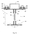
- FIG. 14 An alternative embodiment of the mounting unit is in FIG. 14 shown.
- This mounting unit also has a support plate 966, which has a connection to a web part in the form of a threaded rod 963 on the underside and from the top side a plurality of clamping bolts 922 extend in the form of threaded bolts, which are connected to the support plate either materially or such that a joining surface between the clamping bolt and the clamping plate has no passage through the support plate 966.
- a welded joint between the clamping bolt and the support plate can also find a screw application, in which case a blind hole is formed in the support plate, which is provided with an internal thread.
- a mounting body 914 for the structures seated on the support plate is surrounded by a clamping ring 915.
- the clamping ring 915 is clamped by means of the clamping bolt 922 against the support plate with the interposition of the support plate 966 on all sides superior sealing sleeve, whereby after welding the sealing sleeve 842 with the rest of the roof skin can ensure a perfect seal of the roof, as with reference to the embodiments of the FIGS. 1 to 12 is described.
- the clamping or clamping force of the clamping bolt 922 on the Sealing collar 942 at least on one side via a sealing insert in the form of annular discs 946 and 947 are initiated.
- the web part can again be formed by a threaded rod 963 or tube, wherein the support plate 966 can carry on the underside a nut 964.
- the web portion 963 may be connected to the support plate to a manageable unit, which is then inserted into a receptacle 962 of the base part 916, for example, screwed.
- the mounting body 614 - as in the Figures 11 and 12 shown - be provided with a threaded rod 672, 772, to which an object, such as the Unterertragkonstrutation a photovoltaic system 48, can be attached.
- the length of the threaded rod 672, 772 can be chosen so that it also allows a margin for height adjustment of the object to be fastened in addition to the attachment.
- threaded rod 672, 772 provided with an external thread
- a tube with an internal thread which is provided with a thread corresponding threaded bolt on the fastening object screwed and height adjustable.
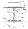
- Fig. 15 shows a further embodiment of a not included in the invention fastening device in which the connection between the projection portion 1018 and mounting body 1014 is not frictionally, for example by a roof seal 1038 or sealing collar 1042 penetrating screw connection, but via a welded connection.
- the protruding section 1018 and the mounting body 1014 have coatings 1076 and 1077, respectively, which can be connected to the seal 1038 or the sealing collar 1042, for example by induction welding or other suitable welding methods.
- appropriate materials are to be selected, which are compatible with the material of the seal 1038 or sealing collar 1042. These include, inter alia, high polymer plastics, especially thermoplastics.
- the projection portion 1018 or the mounting body can be materially connected to the seal 1038, 1042.
- the mounting body 1014 and the protrusion portion 1018 are each positioned so as to be aligned with each other, so that tensile and compressive forces can be transmitted from the mounting body 1014 via the seal 1038 to the protrusion portion.
- the advantage of a cohesive connection is in particular that an introduction of force is ensured in the supporting structure of the building exterior surface, without having to penetrate the seal for fixing the mounting body. This prevents moisture from entering the building interior.
- the web part can again be formed by a threaded rod 1063 or tube, wherein the support plate 1066 can carry a screw nut 1064 on the underside.
- the web portion 1063 may be connected to the support plate to a manageable unit, which is then inserted into a receptacle 1062 of the base part 1016, for example, screwed.
- the fastening device according to the invention can also be used in conjunction with a reversing roof.
- Inverted roofs are generally used in solid construction roof constructions.
- the height of the protrusion portion may be much smaller since the seal is directly on the roof support structure.
- the sealing sleeve is connected directly to the seal located on the roof support structure sealing. Accordingly, the height of the mounting body to enlarge so that it penetrates the insulation located above the seal and possibly other layers.
- the geometry of the fastening device may, inter alia, also be such that the base portion is round and the projection portion has the shape of a cylinder.
- the mounting body can instead of a closed profile, as it is in Fig. 1 and Fig. 2 is shown, consist of two mutually fastened U-profiles.
- fastening device according to the invention is designed in particular for lightweight roof constructions with trapezoidal sheet metal profiles, but this can be readily used for weight savings in solid roof constructions or other warm-roof constructions.
- a profile plate which preferably conforms to the surface of the trapezoidal profile of the flat roof construction over a plurality of areas.
Claims (9)
- Dispositif de fixation (10) pour des objets (48), en particulier pour des structures tels que des installations photovoltaïques, servant à la fixation au niveau de surfaces extérieures d'immeuble étanchéifiées telles que des structures de toit plat, comprenant :un corps de montage (14), au niveau duquel l'objet (48) à fixer peut être fixé ; etun élément de fixation (12) doté d'au moins une section faisant saillie (18) et d'une section de base (16), sachantque la section de base (16) peut être fixée au niveau de la structure porteuse (28) de la surface extérieure d'immeuble et que la section faisant saillie (18) peut être reliée au corps de montage (14),la section faisant saillie (18) est configurée de telle manière qu'elle fait saillie, sur le côté opposé à la structure porteuse (28), jusqu'à un plan d'un système d'étanchéification (38) se trouvant sur la structure porteuse (28) et traverse ce faisant le système d'étanchéification (38) et éventuellement d'autres couches se trouvant entre la structure porteuse (28) et le système d'étanchéification (38, 42), en particulier une couche d'isolation thermique (36),le dispositif de fixation présente une coupelle d'étanchéification (42) dépassant de tous les côtés de la section faisant saillie (18) et disposée entre le corps de montage (14) et la section faisant saillie (18), laquelle coupelle d'étanchéification est adaptée pour former des sections de chevauchement (44) avec le système d'étanchéification (38) enveloppant et être reliées à ce dernier de manière à assurer l'étanchéité, sachant quela section faisant saillie (18) présente au moins un boulon de serrage ou fileté (22) servant à la fixation du corps de montage (14), lequel est relié à la section faisant saillie (18) par liaison de matière ou de telle manière qu'une surface d'assemblage entre le boulon de serrage (22) et la section faisant saillie (18) ne comporte aucun passage à travers la section faisant saillie (18), etque la coupelle d'étanchéification (42) est enserrée de manière à assurer l'étanchéité entre le corps de montage (14) et la section faisant saillie (18) au moyen du boulon de serrage ou du boulon fileté (22) au moins au nombre de un ; etque le dispositif de fixation (10) peut être fixé, à l'état prémonté, à la coupelle d'étanchéification (42) de la structure porteuse (28) enserrée entre le corps de montage (14) et la section faisant saillie (18),caractérisé en ce que la section faisant saillie (618 ; 718 ; 818) est réglable en hauteur.
- Dispositif de fixation (10) selon la revendication 1, caractérisé en ce qu'une garniture d'étanchéité ou une garniture de pression, telle que par exemple une couche ou une plaque de néoprène (46), est disposée entre le corps de montage (14) et la coupelle d'étanchéification (42) et/ou entre la section faisant saillie (866) et la coupelle d'étanchéification (842).
- Dispositif de fixation (10) selon l'une quelconque des revendications précédentes, caractérisé en ce que la section faisant saillie (18) au moins au nombre de une est appropriée pour faire saillie du système d'étanchéification (38).
- Dispositif de fixation (10) selon l'une quelconque des revendications précédentes, caractérisé en ce que la coupelle d'étanchéification (42) peut être collée ou soudée au système d'étanchéification (38).
- Dispositif de fixation (10) selon l'une quelconque des revendications précédentes, caractérisé en ce que la coupelle d'étanchéification (42) est fabriquée à partir du même matériau que le système d'étanchéification (38) ou à partir d'un matériau compatible afin d'établir une liaison assurant l'étanchéité, en particulier à partir d'un bitume à deux couches ou d'une matière plastique à une couche.
- Dispositif de fixation (10) selon l'une quelconque des revendications précédentes, caractérisé en ce que des alésages (17) sont prévus dans la section de base (16) à des espacements prédéfinis.
- Dispositif de fixation (10) selon l'une quelconque des revendications précédentes, caractérisé en ce que la section de base (16) et la structure porteuse (28) peuvent former une couche formant barrière contre la vapeur (34).
- Dispositif de fixation selon l'une quelconque des revendications précédentes, caractérisé en outre par une section d'isolation (433) constituée d'un matériau présentant une faible conductivité thermique, de préférence une rondelle en plastique dur, qui peut être disposée entre la structure porteuse (428) et la section de base (416) aux fins du découplage thermique du dispositif de fixation (410) et de la structure porteuse (428).
- Dispositif de fixation selon l'une quelconque des revendications précédentes, caractérisé en ce que la section faisant saillie (818) présente :une plaque de support (866), qui peut être reliée au corps de montage (814) ;une section de raccordement supérieure (864), se présentant de préférence sous la forme d'un écrou, à l'aide de laquelle la plaque (866) peut être raccordée à un élément de liaison (863), se présentant de préférence sous la forme d'une tige filetée ;etune section de raccordement inférieure (862), se présentant de préférence sous la forme d'un autre écrou, par l'intermédiaire de laquelle l'élément de liaison (863) peut être raccordé à la section de base (816) et qui est reliée à la section de base (816), sachant quela plaque de support (866) et le corps de montage (814) forment une unité de montage (A) en intercalant la coupelle d'étanchéification (846), ladite unité de montage pouvant être reliée, dans l'état prémonté, par l'intermédiaire de l'élément de liaison (863), à la section de base (816) fixée à la structure porteuse (28) de la surface extérieure d'immeuble.
Priority Applications (1)
| Application Number | Priority Date | Filing Date | Title |
|---|---|---|---|
| EP07722829.4A EP1992017B1 (fr) | 2006-02-16 | 2007-02-15 | Dispositif de fixation d'objets sur des surfaces extérieures étanchées d'immeubles |
Applications Claiming Priority (7)
| Application Number | Priority Date | Filing Date | Title |
|---|---|---|---|
| DE102006007294 | 2006-02-16 | ||
| DE102006013792 | 2006-03-24 | ||
| DE102006022593 | 2006-05-15 | ||
| DE102006022870A DE102006022870A1 (de) | 2006-02-16 | 2006-05-16 | Befestigungsvorrichtung für Gegenstände auf Flachdachkonstruktionen |
| EP2007000274 | 2007-01-12 | ||
| PCT/EP2007/001323 WO2007093421A2 (fr) | 2006-02-16 | 2007-02-15 | Dispositif de fixation d'objets sur des surfaces extérieures étanchées d'immeubles et unité de montage correspondante |
| EP07722829.4A EP1992017B1 (fr) | 2006-02-16 | 2007-02-15 | Dispositif de fixation d'objets sur des surfaces extérieures étanchées d'immeubles |
Publications (2)
| Publication Number | Publication Date |
|---|---|
| EP1992017A2 EP1992017A2 (fr) | 2008-11-19 |
| EP1992017B1 true EP1992017B1 (fr) | 2014-04-16 |
Family
ID=38153446
Family Applications (1)
| Application Number | Title | Priority Date | Filing Date |
|---|---|---|---|
| EP07722829.4A Active EP1992017B1 (fr) | 2006-02-16 | 2007-02-15 | Dispositif de fixation d'objets sur des surfaces extérieures étanchées d'immeubles |
Country Status (3)
| Country | Link |
|---|---|
| EP (1) | EP1992017B1 (fr) |
| DE (2) | DE202007008846U1 (fr) |
| WO (1) | WO2007093421A2 (fr) |
Families Citing this family (23)
| Publication number | Priority date | Publication date | Assignee | Title |
|---|---|---|---|---|
| JP2011512650A (ja) † | 2008-02-02 | 2011-04-21 | レノリット・ベルジャム・ナムローゼ・フエンノートシャップ | 剛性プレート固定用の異形材 |
| DE102008034409B4 (de) * | 2008-07-23 | 2020-02-06 | Wittenauer Gmbh | Foliendurchdringungselement und dessen Verwendung |
| DE102009003165A1 (de) * | 2008-12-05 | 2010-06-17 | Climasol-Solaranlagen Gmbh | Montagesystem und Verfahren zur Montage von Solarmodulen |
| DE202009013602U1 (de) * | 2008-12-05 | 2010-04-15 | Climasol-Solaranlagen Gmbh | Montagesystem |
| US9447988B2 (en) | 2010-01-25 | 2016-09-20 | Rillito Rive Solar, LLC | Roof mount assembly |
| IT1393630B1 (it) * | 2009-03-30 | 2012-05-08 | Marco Pietro Borrini | Sistema per fissare moduli fotovoltaici ad un manto di copertura |
| FR2944568B1 (fr) * | 2009-04-20 | 2015-08-21 | Arcelormittal Construction France | Piece de fixation pour l'assemblage d'un module, notamment photovoltaique, sur une tole nervuree, assemblage et utilisation pour la realisation d'une couverture de batiment |
| DE202009007326U1 (de) | 2009-05-26 | 2009-10-29 | Schweiger, Thomas | Gleitlager zur Befestigung einer Dachtragekonstruktion |
| ITLI20090007A1 (it) * | 2009-07-02 | 2009-10-01 | Antonino Repici | Ultra blocksistema di ancoraggio per pannelli fotovoltaici su coperture con manti bituminosi o sintetici o in lastre di acciaio o in fibrocemento. |
| DE102009033416B3 (de) | 2009-07-16 | 2011-01-13 | Ejot Baubefestigungen Gmbh | Befestigungssystem für Anbauteile |
| DE102010036305A1 (de) | 2010-07-08 | 2012-01-12 | Sfs Intec Holding Ag | Vorrichtung zur Befestigung einer Tragkonstruktion auf einem Flachdach |
| AT12832U1 (de) * | 2011-06-01 | 2012-12-15 | Mage Sunfixings Gmbh | Solar-dachanbindungssystem |
| EP2751847B1 (fr) * | 2011-09-02 | 2019-03-27 | PV Solutions, LLC | Système de montage pour réseaux photovoltaïques |
| US9142967B2 (en) | 2011-09-02 | 2015-09-22 | Pv Solutions, Llc | System for tracking and allocating renewable energy contributions to a modular renewable energy system |
| US11022343B2 (en) | 2011-09-02 | 2021-06-01 | Pv Solutions, Llc | Mounting system for photovoltaic arrays |
| US10008974B2 (en) | 2011-09-02 | 2018-06-26 | Pv Solutions, Llc | Mounting system for photovoltaic arrays |
| GB201209197D0 (en) * | 2012-05-25 | 2012-07-04 | Boyt Paul | Fixing items to building structures |
| US9973142B2 (en) | 2013-03-06 | 2018-05-15 | Vermont Slate and Copper Services, Inc. | Snow fence for a solar panel |
| US9985575B2 (en) | 2014-04-07 | 2018-05-29 | Rillito River Solar, Llc | Height adjustment bracket for roof applications |
| US9431953B2 (en) | 2014-10-31 | 2016-08-30 | Rillito River Solar, Llc | Height adjustment bracket for roof applications |
| WO2016123357A2 (fr) | 2015-01-28 | 2016-08-04 | Pv Solutions, Llc | Système de raccordement de réseau photovoltaïque mécanique et électrique intégré |
| DE102015013086A1 (de) | 2015-10-01 | 2017-04-06 | Jutta Regina Giller | Attika für Gebäude |
| US10469023B2 (en) | 2016-09-12 | 2019-11-05 | EcoFasten Solar, LLC | Roof mounting system |
Family Cites Families (3)
| Publication number | Priority date | Publication date | Assignee | Title |
|---|---|---|---|---|
| FR2676242B1 (fr) | 1991-05-07 | 1997-04-30 | Axter | Ensemble de couverture et de surtoiture. |
| US6526701B2 (en) | 2000-07-03 | 2003-03-04 | Vermont Slate & Copper Services, Inc. | Roof mount |
| DE202004005224U1 (de) | 2004-04-02 | 2004-06-24 | Schüco International KG. | Montagesystem |
-
2007
- 2007-02-15 DE DE202007008846U patent/DE202007008846U1/de not_active Expired - Lifetime
- 2007-02-15 DE DE112007000413T patent/DE112007000413A5/de not_active Withdrawn
- 2007-02-15 WO PCT/EP2007/001323 patent/WO2007093421A2/fr active Application Filing
- 2007-02-15 EP EP07722829.4A patent/EP1992017B1/fr active Active
Also Published As
| Publication number | Publication date |
|---|---|
| EP1992017A2 (fr) | 2008-11-19 |
| DE202007008846U1 (de) | 2007-10-31 |
| WO2007093421A3 (fr) | 2007-12-21 |
| DE112007000413A5 (de) | 2009-04-16 |
| WO2007093421A2 (fr) | 2007-08-23 |
Similar Documents
| Publication | Publication Date | Title |
|---|---|---|
| EP1992017B1 (fr) | Dispositif de fixation d'objets sur des surfaces extérieures étanchées d'immeubles | |
| DE102006022870A1 (de) | Befestigungsvorrichtung für Gegenstände auf Flachdachkonstruktionen | |
| WO2009019181A1 (fr) | Châssis de montage pour la pose intégrée aux bâtiments de modules photovoltaïques et de collecteurs solaires | |
| EP1619727A2 (fr) | Dispositif pour fixer des groupes fonctionnels sur toits plats, spécialement des modules solaires sur des halls industriels | |
| DE2226889A1 (de) | Bausystem, insbesondere zur Ernch tung von Gebäuden, Container und Fahr zeugaufbauten | |
| DE102008012717A1 (de) | Aufnahmeelement | |
| EP3183401B1 (fr) | Structure en béton modulaire | |
| EP2312235A2 (fr) | Support pour modules photovoltaïques sur toits plats | |
| DE102009003165A1 (de) | Montagesystem und Verfahren zur Montage von Solarmodulen | |
| EP1988227B1 (fr) | Toit pour bâtiments | |
| EP1375770A2 (fr) | Panneau composite, assemblage de deux panneaux composites et un demi-produit pour la fabrication d'un tel panneau | |
| DE102009043808A1 (de) | Montagesystem und Dachkonstruktion | |
| DE202009001072U1 (de) | Vorrichtung zur Aufständerung von Solarmodulen | |
| DE102010016677A1 (de) | Punkthalter für Solarmodule | |
| DE3705961A1 (de) | Nachtraeglich anbaubarer balkon | |
| DE102008008923B4 (de) | Leicht handhabbares Gestell für Dachaufbauten an Flachdächern und geneigten Flachdächern | |
| EP2194339A2 (fr) | Profil de chapeau | |
| DE102008035345A1 (de) | Befestigungseinrichtung für Tragkonstruktionen für Solarmodule auf Baukörpern | |
| EP2184418B1 (fr) | Montage d'un module photovoltaic dans une toiture | |
| DE102011000867A1 (de) | Linienbefestigung mit mehreren Adaptern | |
| DE102022127185A1 (de) | Trägerkonstruktion für nichtbelastbare Dächer | |
| DE102009048884A1 (de) | Wasserdichte Dachmatte mit integrierten Befestigungsmitteln für Photovoltaikmodule | |
| DE202010007783U1 (de) | Vorrichtung zur dauerhaften feuchtigkeitsdichten Verbindung mit Gestellen zur Kopplung von Dachaufbauten | |
| DE202009013602U1 (de) | Montagesystem | |
| DE102006003800C5 (de) | Stützelement für eine Dachkonstruktion in Metall-Leichtbauausführung |
Legal Events
| Date | Code | Title | Description |
|---|---|---|---|
| PUAI | Public reference made under article 153(3) epc to a published international application that has entered the european phase |
Free format text: ORIGINAL CODE: 0009012 |
|
| 17P | Request for examination filed |
Effective date: 20080916 |
|
| AK | Designated contracting states |
Kind code of ref document: A2 Designated state(s): AT BE BG CH CY CZ DE DK EE ES FI FR GB GR HU IE IS IT LI LT LU LV MC NL PL PT RO SE SI SK TR |
|
| 17Q | First examination report despatched |
Effective date: 20090122 |
|
| DAX | Request for extension of the european patent (deleted) | ||
| GRAP | Despatch of communication of intention to grant a patent |
Free format text: ORIGINAL CODE: EPIDOSNIGR1 |
|
| INTG | Intention to grant announced |
Effective date: 20131024 |
|
| GRAS | Grant fee paid |
Free format text: ORIGINAL CODE: EPIDOSNIGR3 |
|
| GRAA | (expected) grant |
Free format text: ORIGINAL CODE: 0009210 |
|
| AK | Designated contracting states |
Kind code of ref document: B1 Designated state(s): AT BE BG CH CY CZ DE DK EE ES FI FR GB GR HU IE IS IT LI LT LU LV MC NL PL PT RO SE SI SK TR |
|
| REG | Reference to a national code |
Ref country code: GB Ref legal event code: FG4D Free format text: NOT ENGLISH |
|
| REG | Reference to a national code |
Ref country code: CH Ref legal event code: EP |
|
| REG | Reference to a national code |
Ref country code: AT Ref legal event code: REF Ref document number: 663003 Country of ref document: AT Kind code of ref document: T Effective date: 20140515 |
|
| REG | Reference to a national code |
Ref country code: IE Ref legal event code: FG4D Free format text: LANGUAGE OF EP DOCUMENT: GERMAN |
|
| REG | Reference to a national code |
Ref country code: DE Ref legal event code: R096 Ref document number: 502007012989 Country of ref document: DE Effective date: 20140522 |
|
| REG | Reference to a national code |
Ref country code: NL Ref legal event code: VDEP Effective date: 20140416 |
|
| REG | Reference to a national code |
Ref country code: LT Ref legal event code: MG4D |
|
| PG25 | Lapsed in a contracting state [announced via postgrant information from national office to epo] |
Ref country code: LT Free format text: LAPSE BECAUSE OF FAILURE TO SUBMIT A TRANSLATION OF THE DESCRIPTION OR TO PAY THE FEE WITHIN THE PRESCRIBED TIME-LIMIT Effective date: 20140416 Ref country code: CY Free format text: LAPSE BECAUSE OF FAILURE TO SUBMIT A TRANSLATION OF THE DESCRIPTION OR TO PAY THE FEE WITHIN THE PRESCRIBED TIME-LIMIT Effective date: 20140416 Ref country code: GR Free format text: LAPSE BECAUSE OF FAILURE TO SUBMIT A TRANSLATION OF THE DESCRIPTION OR TO PAY THE FEE WITHIN THE PRESCRIBED TIME-LIMIT Effective date: 20140717 Ref country code: BG Free format text: LAPSE BECAUSE OF FAILURE TO SUBMIT A TRANSLATION OF THE DESCRIPTION OR TO PAY THE FEE WITHIN THE PRESCRIBED TIME-LIMIT Effective date: 20140716 Ref country code: NL Free format text: LAPSE BECAUSE OF FAILURE TO SUBMIT A TRANSLATION OF THE DESCRIPTION OR TO PAY THE FEE WITHIN THE PRESCRIBED TIME-LIMIT Effective date: 20140416 Ref country code: FI Free format text: LAPSE BECAUSE OF FAILURE TO SUBMIT A TRANSLATION OF THE DESCRIPTION OR TO PAY THE FEE WITHIN THE PRESCRIBED TIME-LIMIT Effective date: 20140416 Ref country code: IS Free format text: LAPSE BECAUSE OF FAILURE TO SUBMIT A TRANSLATION OF THE DESCRIPTION OR TO PAY THE FEE WITHIN THE PRESCRIBED TIME-LIMIT Effective date: 20140816 |
|
| PG25 | Lapsed in a contracting state [announced via postgrant information from national office to epo] |
Ref country code: ES Free format text: LAPSE BECAUSE OF FAILURE TO SUBMIT A TRANSLATION OF THE DESCRIPTION OR TO PAY THE FEE WITHIN THE PRESCRIBED TIME-LIMIT Effective date: 20140416 Ref country code: PL Free format text: LAPSE BECAUSE OF FAILURE TO SUBMIT A TRANSLATION OF THE DESCRIPTION OR TO PAY THE FEE WITHIN THE PRESCRIBED TIME-LIMIT Effective date: 20140416 Ref country code: LV Free format text: LAPSE BECAUSE OF FAILURE TO SUBMIT A TRANSLATION OF THE DESCRIPTION OR TO PAY THE FEE WITHIN THE PRESCRIBED TIME-LIMIT Effective date: 20140416 Ref country code: SE Free format text: LAPSE BECAUSE OF FAILURE TO SUBMIT A TRANSLATION OF THE DESCRIPTION OR TO PAY THE FEE WITHIN THE PRESCRIBED TIME-LIMIT Effective date: 20140416 |
|
| PG25 | Lapsed in a contracting state [announced via postgrant information from national office to epo] |
Ref country code: PT Free format text: LAPSE BECAUSE OF FAILURE TO SUBMIT A TRANSLATION OF THE DESCRIPTION OR TO PAY THE FEE WITHIN THE PRESCRIBED TIME-LIMIT Effective date: 20140818 |
|
| REG | Reference to a national code |
Ref country code: DE Ref legal event code: R097 Ref document number: 502007012989 Country of ref document: DE |
|
| PG25 | Lapsed in a contracting state [announced via postgrant information from national office to epo] |
Ref country code: EE Free format text: LAPSE BECAUSE OF FAILURE TO SUBMIT A TRANSLATION OF THE DESCRIPTION OR TO PAY THE FEE WITHIN THE PRESCRIBED TIME-LIMIT Effective date: 20140416 Ref country code: DK Free format text: LAPSE BECAUSE OF FAILURE TO SUBMIT A TRANSLATION OF THE DESCRIPTION OR TO PAY THE FEE WITHIN THE PRESCRIBED TIME-LIMIT Effective date: 20140416 Ref country code: SK Free format text: LAPSE BECAUSE OF FAILURE TO SUBMIT A TRANSLATION OF THE DESCRIPTION OR TO PAY THE FEE WITHIN THE PRESCRIBED TIME-LIMIT Effective date: 20140416 Ref country code: CZ Free format text: LAPSE BECAUSE OF FAILURE TO SUBMIT A TRANSLATION OF THE DESCRIPTION OR TO PAY THE FEE WITHIN THE PRESCRIBED TIME-LIMIT Effective date: 20140416 Ref country code: RO Free format text: LAPSE BECAUSE OF FAILURE TO SUBMIT A TRANSLATION OF THE DESCRIPTION OR TO PAY THE FEE WITHIN THE PRESCRIBED TIME-LIMIT Effective date: 20140416 |
|
| PLBE | No opposition filed within time limit |
Free format text: ORIGINAL CODE: 0009261 |
|
| STAA | Information on the status of an ep patent application or granted ep patent |
Free format text: STATUS: NO OPPOSITION FILED WITHIN TIME LIMIT |
|
| 26N | No opposition filed |
Effective date: 20150119 |
|
| REG | Reference to a national code |
Ref country code: DE Ref legal event code: R097 Ref document number: 502007012989 Country of ref document: DE Effective date: 20150119 |
|
| PG25 | Lapsed in a contracting state [announced via postgrant information from national office to epo] |
Ref country code: BE Free format text: LAPSE BECAUSE OF NON-PAYMENT OF DUE FEES Effective date: 20150228 |
|
| PG25 | Lapsed in a contracting state [announced via postgrant information from national office to epo] |
Ref country code: SI Free format text: LAPSE BECAUSE OF FAILURE TO SUBMIT A TRANSLATION OF THE DESCRIPTION OR TO PAY THE FEE WITHIN THE PRESCRIBED TIME-LIMIT Effective date: 20140416 |
|
| PG25 | Lapsed in a contracting state [announced via postgrant information from national office to epo] |
Ref country code: LU Free format text: LAPSE BECAUSE OF FAILURE TO SUBMIT A TRANSLATION OF THE DESCRIPTION OR TO PAY THE FEE WITHIN THE PRESCRIBED TIME-LIMIT Effective date: 20150215 |
|
| REG | Reference to a national code |
Ref country code: CH Ref legal event code: PL |
|
| GBPC | Gb: european patent ceased through non-payment of renewal fee |
Effective date: 20150215 |
|
| PG25 | Lapsed in a contracting state [announced via postgrant information from national office to epo] |
Ref country code: MC Free format text: LAPSE BECAUSE OF FAILURE TO SUBMIT A TRANSLATION OF THE DESCRIPTION OR TO PAY THE FEE WITHIN THE PRESCRIBED TIME-LIMIT Effective date: 20140416 Ref country code: LI Free format text: LAPSE BECAUSE OF NON-PAYMENT OF DUE FEES Effective date: 20150228 Ref country code: CH Free format text: LAPSE BECAUSE OF NON-PAYMENT OF DUE FEES Effective date: 20150228 |
|
| REG | Reference to a national code |
Ref country code: IE Ref legal event code: MM4A |
|
| REG | Reference to a national code |
Ref country code: FR Ref legal event code: ST Effective date: 20151030 |
|
| PG25 | Lapsed in a contracting state [announced via postgrant information from national office to epo] |
Ref country code: IE Free format text: LAPSE BECAUSE OF NON-PAYMENT OF DUE FEES Effective date: 20150215 Ref country code: GB Free format text: LAPSE BECAUSE OF NON-PAYMENT OF DUE FEES Effective date: 20150215 |
|
| PG25 | Lapsed in a contracting state [announced via postgrant information from national office to epo] |
Ref country code: FR Free format text: LAPSE BECAUSE OF NON-PAYMENT OF DUE FEES Effective date: 20150302 |
|
| PG25 | Lapsed in a contracting state [announced via postgrant information from national office to epo] |
Ref country code: HU Free format text: LAPSE BECAUSE OF FAILURE TO SUBMIT A TRANSLATION OF THE DESCRIPTION OR TO PAY THE FEE WITHIN THE PRESCRIBED TIME-LIMIT; INVALID AB INITIO Effective date: 20070215 |
|
| PG25 | Lapsed in a contracting state [announced via postgrant information from national office to epo] |
Ref country code: TR Free format text: LAPSE BECAUSE OF FAILURE TO SUBMIT A TRANSLATION OF THE DESCRIPTION OR TO PAY THE FEE WITHIN THE PRESCRIBED TIME-LIMIT Effective date: 20140416 |
|
| PGFP | Annual fee paid to national office [announced via postgrant information from national office to epo] |
Ref country code: AT Payment date: 20230215 Year of fee payment: 17 |
|
| PGFP | Annual fee paid to national office [announced via postgrant information from national office to epo] |
Ref country code: IT Payment date: 20230228 Year of fee payment: 17 Ref country code: DE Payment date: 20230111 Year of fee payment: 17 |