EP1992017B1 - Fastening device for fastening objects on sealed outer building surfaces - Google Patents
Fastening device for fastening objects on sealed outer building surfaces Download PDFInfo
- Publication number
- EP1992017B1 EP1992017B1 EP07722829.4A EP07722829A EP1992017B1 EP 1992017 B1 EP1992017 B1 EP 1992017B1 EP 07722829 A EP07722829 A EP 07722829A EP 1992017 B1 EP1992017 B1 EP 1992017B1
- Authority
- EP
- European Patent Office
- Prior art keywords
- fastening device
- mounting body
- seal
- section
- projecting section
- Prior art date
- Legal status (The legal status is an assumption and is not a legal conclusion. Google has not performed a legal analysis and makes no representation as to the accuracy of the status listed.)
- Active
Links
Images

Classifications
-
- H—ELECTRICITY
- H02—GENERATION; CONVERSION OR DISTRIBUTION OF ELECTRIC POWER
- H02S—GENERATION OF ELECTRIC POWER BY CONVERSION OF INFRARED RADIATION, VISIBLE LIGHT OR ULTRAVIOLET LIGHT, e.g. USING PHOTOVOLTAIC [PV] MODULES
- H02S20/00—Supporting structures for PV modules
- H02S20/20—Supporting structures directly fixed to an immovable object
- H02S20/22—Supporting structures directly fixed to an immovable object specially adapted for buildings
- H02S20/23—Supporting structures directly fixed to an immovable object specially adapted for buildings specially adapted for roof structures
-
- F—MECHANICAL ENGINEERING; LIGHTING; HEATING; WEAPONS; BLASTING
- F24—HEATING; RANGES; VENTILATING
- F24S—SOLAR HEAT COLLECTORS; SOLAR HEAT SYSTEMS
- F24S25/00—Arrangement of stationary mountings or supports for solar heat collector modules
- F24S25/30—Arrangement of stationary mountings or supports for solar heat collector modules using elongate rigid mounting elements extending substantially along the supporting surface, e.g. for covering buildings with solar heat collectors
-
- F—MECHANICAL ENGINEERING; LIGHTING; HEATING; WEAPONS; BLASTING
- F24—HEATING; RANGES; VENTILATING
- F24S—SOLAR HEAT COLLECTORS; SOLAR HEAT SYSTEMS
- F24S25/00—Arrangement of stationary mountings or supports for solar heat collector modules
- F24S25/60—Fixation means, e.g. fasteners, specially adapted for supporting solar heat collector modules
- F24S25/61—Fixation means, e.g. fasteners, specially adapted for supporting solar heat collector modules for fixing to the ground or to building structures
-
- F—MECHANICAL ENGINEERING; LIGHTING; HEATING; WEAPONS; BLASTING
- F24—HEATING; RANGES; VENTILATING
- F24S—SOLAR HEAT COLLECTORS; SOLAR HEAT SYSTEMS
- F24S25/00—Arrangement of stationary mountings or supports for solar heat collector modules
- F24S25/60—Fixation means, e.g. fasteners, specially adapted for supporting solar heat collector modules
- F24S25/65—Fixation means, e.g. fasteners, specially adapted for supporting solar heat collector modules for coupling adjacent supporting elements, e.g. for connecting profiles together
-
- F—MECHANICAL ENGINEERING; LIGHTING; HEATING; WEAPONS; BLASTING
- F24—HEATING; RANGES; VENTILATING
- F24S—SOLAR HEAT COLLECTORS; SOLAR HEAT SYSTEMS
- F24S25/00—Arrangement of stationary mountings or supports for solar heat collector modules
- F24S25/70—Arrangement of stationary mountings or supports for solar heat collector modules with means for adjusting the final position or orientation of supporting elements in relation to each other or to a mounting surface; with means for compensating mounting tolerances
-
- F—MECHANICAL ENGINEERING; LIGHTING; HEATING; WEAPONS; BLASTING
- F24—HEATING; RANGES; VENTILATING
- F24S—SOLAR HEAT COLLECTORS; SOLAR HEAT SYSTEMS
- F24S25/00—Arrangement of stationary mountings or supports for solar heat collector modules
- F24S2025/01—Special support components; Methods of use
- F24S2025/021—Sealing means between support elements and mounting surface
-
- F—MECHANICAL ENGINEERING; LIGHTING; HEATING; WEAPONS; BLASTING
- F24—HEATING; RANGES; VENTILATING
- F24S—SOLAR HEAT COLLECTORS; SOLAR HEAT SYSTEMS
- F24S25/00—Arrangement of stationary mountings or supports for solar heat collector modules
- F24S25/60—Fixation means, e.g. fasteners, specially adapted for supporting solar heat collector modules
- F24S2025/6006—Fixation means, e.g. fasteners, specially adapted for supporting solar heat collector modules by using threaded elements, e.g. stud bolts
-
- Y—GENERAL TAGGING OF NEW TECHNOLOGICAL DEVELOPMENTS; GENERAL TAGGING OF CROSS-SECTIONAL TECHNOLOGIES SPANNING OVER SEVERAL SECTIONS OF THE IPC; TECHNICAL SUBJECTS COVERED BY FORMER USPC CROSS-REFERENCE ART COLLECTIONS [XRACs] AND DIGESTS
- Y02—TECHNOLOGIES OR APPLICATIONS FOR MITIGATION OR ADAPTATION AGAINST CLIMATE CHANGE
- Y02B—CLIMATE CHANGE MITIGATION TECHNOLOGIES RELATED TO BUILDINGS, e.g. HOUSING, HOUSE APPLIANCES OR RELATED END-USER APPLICATIONS
- Y02B10/00—Integration of renewable energy sources in buildings
- Y02B10/10—Photovoltaic [PV]
-
- Y—GENERAL TAGGING OF NEW TECHNOLOGICAL DEVELOPMENTS; GENERAL TAGGING OF CROSS-SECTIONAL TECHNOLOGIES SPANNING OVER SEVERAL SECTIONS OF THE IPC; TECHNICAL SUBJECTS COVERED BY FORMER USPC CROSS-REFERENCE ART COLLECTIONS [XRACs] AND DIGESTS
- Y02—TECHNOLOGIES OR APPLICATIONS FOR MITIGATION OR ADAPTATION AGAINST CLIMATE CHANGE
- Y02B—CLIMATE CHANGE MITIGATION TECHNOLOGIES RELATED TO BUILDINGS, e.g. HOUSING, HOUSE APPLIANCES OR RELATED END-USER APPLICATIONS
- Y02B10/00—Integration of renewable energy sources in buildings
- Y02B10/20—Solar thermal
-
- Y—GENERAL TAGGING OF NEW TECHNOLOGICAL DEVELOPMENTS; GENERAL TAGGING OF CROSS-SECTIONAL TECHNOLOGIES SPANNING OVER SEVERAL SECTIONS OF THE IPC; TECHNICAL SUBJECTS COVERED BY FORMER USPC CROSS-REFERENCE ART COLLECTIONS [XRACs] AND DIGESTS
- Y02—TECHNOLOGIES OR APPLICATIONS FOR MITIGATION OR ADAPTATION AGAINST CLIMATE CHANGE
- Y02E—REDUCTION OF GREENHOUSE GAS [GHG] EMISSIONS, RELATED TO ENERGY GENERATION, TRANSMISSION OR DISTRIBUTION
- Y02E10/00—Energy generation through renewable energy sources
- Y02E10/40—Solar thermal energy, e.g. solar towers
- Y02E10/47—Mountings or tracking
-
- Y—GENERAL TAGGING OF NEW TECHNOLOGICAL DEVELOPMENTS; GENERAL TAGGING OF CROSS-SECTIONAL TECHNOLOGIES SPANNING OVER SEVERAL SECTIONS OF THE IPC; TECHNICAL SUBJECTS COVERED BY FORMER USPC CROSS-REFERENCE ART COLLECTIONS [XRACs] AND DIGESTS
- Y02—TECHNOLOGIES OR APPLICATIONS FOR MITIGATION OR ADAPTATION AGAINST CLIMATE CHANGE
- Y02E—REDUCTION OF GREENHOUSE GAS [GHG] EMISSIONS, RELATED TO ENERGY GENERATION, TRANSMISSION OR DISTRIBUTION
- Y02E10/00—Energy generation through renewable energy sources
- Y02E10/50—Photovoltaic [PV] energy
Definitions
- the invention relates to a fastening device for objects, in particular for structures such as photovoltaic systems, on sealed exterior building surfaces such.
- Flat roof constructions according to the preamble of claim 1.
- ballastings of the substructure known from solid flat roofs are usually unsuitable for static reasons.
- a fastening device according to the preamble of claim 1 is made FR 2 676 242 A1 known.
- a mounting unit according to the preamble of claim 11 is made US 2002/0066235 A1 known
- the invention is therefore based on the object, an attachment device for objects on sealed exterior building surfaces such. to create for flat roof structures, which ensures a flexible and sufficient attachment of objects or structures with the least possible additional burden.
- the object to be fastened is fastened directly to the roof structure via the mounting body and the fastening element, so that the object is adequately secured in the case of wind forces or the like. Due to the direct attachment to the support structure can be dispensed with an additional ballast, so that the fastening device according to the invention especially for lightweight roof constructions, but also for Solid roof structures with low reserve capacity is suitable. By bridging the force of the object directly on the roof construction, the other roof layers, such as the seal and the thermal insulation, are not further burdened. Furthermore, a secure sealing of the penetration point is ensured via the sealing collar and based on a so-called.
- a sealing collar located between the mounting body and the protruding section forms overlapping sections with the sealing of the building exterior surface or the roof and can be sealingly connected thereto.
- the fastening device according to the invention is thus not only suitable for new buildings, but can also be retrofitted without much effort on existing flat roofs by the over the support structure layer package located (insulation, sealing, etc.) is only selectively opened to the introduction of the fastener and then sealed again by means of sealing sleeve and loose and fixed flange connection between the mounting body and fastener.
- the base portion of the fastener can be mounted on hot roofs directly on the support structure located on the vapor barrier layer, so that they need not be removed for mounting the fastening device.
- the sealing collar is secured by means of a tightening means, e.g. a screw between the mounting body and projection portion pressed tight.
- a tightening means e.g. a screw between the mounting body and projection portion pressed tight.
- a tightening means e.g. a screw between the mounting body and projection portion pressed tight.
- Such an entrapment can take place on the basis of a loose and fixed flange construction according to DIN 18195 T9.
- DIN 18195 T9 This makes it easy to securely seal the connection between the mounting body and fastener.
- a simple clamping connection can be realized by a screw connection.
- it can equally apply to any other clamping connection, for example, a clamping connection with at least one clamping bolt, which is on the one hand connected to the projection portion and on the other hand cooperates with a device with which the mounting body is clamped against the projection portion.
- the clamping or screw connection is such that at least one or more clamping or threaded bolts or clamping or screw connections are mounted for attaching the mounting body either materially or such that a joining surface between the clamping bolt and the projecting portion does not pass through the projecting portion Has. This means that even with water entering between the mounting body and protrusion portion no moisture on the joining surface, such as the thread can enter through the protruding portion in the roof interior.
- the projection portion is height adjustable.
- the universal fastening device can be adapted to the respective conditions on site. An adaptation already in the production of the fastening device is thus eliminated.
- the height adjustment can be done in different ways.
- a particularly simple handling is characterized by a two-piece bolt, of which one portion has a thread which can be screwed to the mating thread of the other pin portion.
- the position of the two bolt sections relative to one another and thus the distance between the end face of the projecting section and the supporting structure can be set in a simple manner and the respective thickness of the thermal insulation and the other layers adapted.
- the fastening device can be fastened to the supporting structure in the preassembled state with the sealing collar clamped between the mounting body and the protruding section.
- a sealing or pressure supplement such as a neoprene layer or plate, may additionally be provided between the mounting body and the sealing collar and / or between the projection section and the sealing collar.
- This seal or pressure supplement for example, as a neoprene layer ensures a uniform contact pressure between the mounting body and fastener and compensates for any bumps in the sealing sleeve, so that a secure seal is guaranteed.
- a material for the seal or pressure supplement and the material of the sealing sleeve can be used. Basically, the material and / or the geometry of the seal or pressure supplement to the present Adjusted boundary conditions, such as the thickness and / or the compressibility of the clamped layer, so that a maximum and sealing effect is ensured.
- Mounting body and projection portion can not only be frictionally, e.g. connect via a screw connection with each other, but also cohesively, e.g. by suitable welding methods, in particular heat welding or induction welding, or by gluing.
- the mounting body and the protrusion portion When joined by a welding process, the mounting body and the protrusion portion have coatings at appropriate locations so that they can be welded respectively to the seal or the sealing collar and connected to each other via the seal or the sealing collar.
- appropriate materials compatible with the material of the seal or of the sealing sleeve are to be selected for the coating of the mounting body and of the protruding section.
- the height of the protrusion portion may be selected so that the end surface of the protrusion portion is flush with the seal.
- the height of the protruding portion of the fastener may preferably be selected so that it protrudes beyond the seal, so that the level of the connecting portion in the Usually located above the water-bearing layer of the roof waterproofing.
- sealing sleeve and seal both can be welded together or tightly glued.
- Such an approach has is well proven in repair work on flat roofs, especially if the material used for the sealing sleeve the same material as in the seal or at least a compatible material which can be sealingly connected to the seal.
- the material used for the sealing sleeve the same material as in the seal or at least a compatible material which can be sealingly connected to the seal.
- mono- or multilayer bituminous or plastic layers have proven to be particularly suitable.
- the mounting body and / or the fastening element is advantageously made of stainless steel, e.g. V2A produced, which in addition to a sufficient strength, a good corrosion resistance is provided.
- the fastening device according to the invention can be used for a wide variety of roof structures, in particular with trapezoidal sheet metal roofs with differently wide and / or spaced upper belts with simple assembly handling. Due to the existing hole pattern assembly is greatly simplified. Nevertheless, due to the enlarged compared to the projecting portion surface of the base portion ensured that always one or the other bore in coincidence with a top chord and with high probability even with multiple top chords of the trapezoidal sheet comes, so that a standard fastener is created, which is suitable for a variety of trapezoidal roofs suitable is.
- the attachment point pattern is no longer coupled with the geometry of the flax roof and no longer to the orientation of the flat roof construction. This is especially important for photovoltaic systems, because these then independent of the building direction can be aligned preferably to the south.
- the surface of the base portion is preferably adapted to the supporting structure of the building exterior surface or the flat roof. It may be limited in certain applications to the base of a spacer bolt, which then forms the projection portion at the same time.
- the cavity formed by or bridged by the projecting portion can be insulated with insulating material, e.g. with the insulating material that has been removed before the introduction of the fastener from the roof, filled.
- fastening device can be used in conjunction with all common supporting structures, such as concrete, steel, wood, Trapezblechblechkonstrutationen and others, so that it is a very flexible usable device.
- the fixation of the position of the two bolt sections to one another can preferably take place via a lock nut.
- an insulating section can preferably be arranged between the base section and the supporting structure, which thermally decouples the fastening device from the supporting structure of the building exterior surface, so that no heat or cold is conducted via the fastening device into the building interior.
- the storage can be kept simple even when fastening devices for a variety of roof structures, especially different thicknesses to be provided in a very short time, the core of the fastening device is combined to form a mounting unit, which is the subject of the independent claims.
- This mounting unit is pre-assembled in such a way that the sealing collar with a predetermined blank is already firmly clamped and sealed all around.
- the mounting plates can be uniformly formed for all applications, so that only the web parts must be kept variable. The web parts are therefore vorzuhalten in different lengths.
- the web parts can also be pre-assembled with either the support plate or with the mounting plate to a manageable unit.
- the clamping or clamping force of the at least one clamping bolt can be introduced to the sealing sleeve on at least one side via a sealing shim.
- the web portion may be formed by a threaded rod or tube, in which case the support plate carries either a screw nut or a threaded bolt on the underside.
- the assembly unit which can be handled as a unit can also be expanded by the web part and even by the mounting plate.
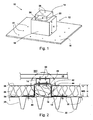
- Fig. 1 shows a perspective view of the fastening device 10 with a fastening element 12 and a mounting body 14.
- the fastening element 12 has a base portion 16 and a projection portion 18. How out Fig. 1 it can also be seen, the projection portion 18 is centered on the base portion 16 is arranged. However, the fastener 12 may have not only one but also a plurality of distributed protrusion portions 18 of the same height.
- the projection portion 18 is cuboid or cube-shaped, is secured to the end face 20 by means of clamping or threaded bolt 22 or a normal screw the mounting body 14.
- the projection portion may also be designed differently and, for example, have the shape of a cylinder, cone or truncated pyramid.
- the mounting body 14 is formed by an open, extruded or otherwise manufactured box profile having on the end face 20 of the protruding portion 18 side facing holes 24 for the clamping or threaded bolt 22 and on the opposite side has holes 26 for fixing an object.
- This article may be, for example, a substructure for photovoltaic systems, elevated maintenance route or escape route constructions, lightning protection or antenna devices, and the like.
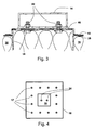
- the base portion 16 of the fastener 12 is attached to the upper straps 30 and over the vapor barrier 34 with fasteners 40, such as tilting dowels or the like.
- the height H of the protrusion portion 18 is set to be greater than the height WD of the thermal insulation 36 and the comparatively thin seal 38 together, so that the end surface 20 of the protrusion portion 18 protrudes beyond the seal 38.
- a sealing collar 42 is disposed so as to form overlapping portions 44 with the surrounding seal 38 of the roof. At the overlapping portions 44, the sealing collar 42 is sealed to the seal 38, eg, by welding or Sealing, sealingly connected.
- the same material as in the seal 38 for example, a two-layered bituminous or a single-layer plastic layer can be used.
- a neoprene plate 46, plastic plate or the like can be arranged, which is sealingly clamped together with the sealing sleeve by the mounting body 14 fastened above.
- recesses for the screw connection between mounting body 14 and fastening element 12 are provided in the sealing collar 42 and in the neoprene plate 46.
- the fastening device is not subsequently mounted on an already flat roof, but is taken into account in the new building, it is possible to attach the fastener 12 to the support structure 28 before the insulation 36 and the seal 38 are laid on the flat roof. Since in this case the seal 38 does not first have to be opened and then sealed again by means of the sealing collar 42, the newly laid seal 38 itself can be clamped between the mounting body 14 and the projection section 18.
- the construction is like in Fig. 2 shown, except that just instead of the sealing collar 42, the seal 38 is clamped continuously between the mounting body 14 and projection portion 18 of the fastener 12.
- one or more clamping or threaded bolts 22 protrude from the end face 20, which are carried out from the inside by recesses in the end face wall of the protruding section 18 and are subsequently welded to the protruding section (see FIG Fig. 3 ). In this way, it is ensured that no moisture can penetrate into the interior of the fastening element 12 and into the interior of the building via the threaded screw connections.
- the object to be fastened for example the base support 48 of a photovoltaic system, is fastened to the mounting body 14 with any fastening element 50.
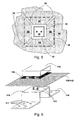
- Fig. 4 In the plan view of Fig. 4 are clearly the preferably prefabricated holes 17 in the base portion and the holes 24 in the projection portion 18 can be seen.
- more holes 17 are provided in the base portion than they would be necessary for attachment to the roof structure, eg on a concrete floor or in the embodiment shown here on the trapezoidal sheet 28.
- a rectangular base whose one side length is at least 400mm for the base portion and 200x200mm for the end face 20 of the projecting portion 18 have been found to be practicable dimensions.
- the subject invention is not limited to these dimensions.
- the fastener 10 i. the fastener 12 and the mounting body 14, made of stainless steel, e.g. made of V2A, galvanized steel or composite construction materials.
- the fastening device 10 can not only be installed in new roof roofs, but also subsequently in existing flat roofs.
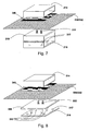
- Fig. 5 When retrofitting is how out Fig. 5 It can be seen, cut out of the seal 38 and the thermal insulation material 36 in about the size of the protruding portion 18 or removed.
- sealing 38 and thermal insulation 36 are slit in such a way that the slots 52 correspond approximately to the diagonal of the rectangular base of the base portion 16.
- These slots 52 are sufficient to be able to fold up the four formed by the slots 52 trapezoidal portions 54 of the seal 38 and insulation 36 so that the fastener 12 is introduced with the base portion 16 ahead under the seal 38 and insulation 36 and secured to the trapezoidal sheet 28 can be.
- subsequently introduced into the seal 38 slots 52 for example with the aid of Abdichtbahnen 56 or one of the slots 52 overlapping sealing collar 42, are sealed again.
- FIGS. 6 to 10 Further embodiments of the fastening device and the fastener are shown. To simplify the description, those components that correspond to the components of the previously described embodiment are given identical or similar reference numerals, preceded by another digit.
- Fig. 6 shows a configured as an angle profile fastener 112.
- the base portions 116 are provided with a hole pattern.
- fastener 212 shown is formed from a sheet to a rectangular hollow profile, one (lower) side of the base portion 216 and the other three sides of the projecting portion 218 form.
- the fastening element formed in this way can, for example, be materially connected, preferably welded, to the abutting edges.
- the projection portions 318 are modified. They are formed by a plurality of bolts 362 which are fixed to a base plate 366 and the upper side carrying a plate, which in turn - as in the embodiment of the FIGS. 1 to 5 - Is connected to the clamping or threaded bolts 322 material fit.
- the base surface of the base portion 16, 216, 316 is preferably chosen so that it covers a sufficiently large area with the hole pattern 17, 117, 317, so that a sufficient number of holes 17, 117, 317 lie over bearing areas of the supporting structure of the sealed exterior building surface come.
- the footprint can also be reduced, which is based on the following embodiments according to the Figures 9 and 10 should be explained. These figures represent almost true to scale cuts of fasteners.
- the base portion 416 a surface much smaller plate - for example, with an edge dimension of about 100 x 100 mm - which is equipped with a plurality of holes 417 and a stud 462 (for example, bar steel with a diameter of 15 to 20 mm) contributes or with this is welded.
- the stud bolt 462 passes over a shoulder into a clamping or threaded section 422.
- a support plate 466 On the shoulder is a support plate 466, which may be about the same size as the base plate 416 and against - as in connection with the FIGS. 1 to 5 described over the plate 446 and the seal 438, 442 of the mounting body 414 is tensioned.
- the bridged by the stud bolts 462 space is in turn filled by a thermal insulation 436.
- the fastening device 410 and the supporting structure 428 of the building exterior surface may additionally between the base portion 416 and the support structure 428, preferably between the base portion 416 and the vapor barrier 434, an insulating portion 433 of a material with the lowest possible thermal conductivity, for. made of hard plastic or other suitable materials.
- the insulating portion 433 may advantageously consist of the material of the roof skin. In this case, in retrofitted fastening devices previously removed from the roof skin piece of roofing can be used.
- the variant can FIG. 10 be used.
- the base surface of the base portion 516 is reduced here to the cross-sectional area of the stud bolt 562, which is anchored by means of a recessed drill screw 560 on the support structure 528, where there is a sufficiently high stability.
- this embodiment corresponds to the variant of FIG. 9 ,
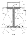
- FIG. 11 shows a variant of the embodiment according to the invention FIG. 9 which provides a length-adjustable projection portion 618.
- This height adjustment of the projecting portion 618 allows the universal use of the fastening device 10 according to the invention for different thickness layer packages (thermal insulation, sealing, vapor barrier, etc.) on the building exterior surfaces.
- the Length or height adjustment of the projection portion 618 may, for example - as in FIG. 11 shown by a two-part stud 662, 664, the lower bolt portion 662 is connected to the base portion 616 and the upper bolt portion 664 carries a support plate 666, which in turn - as in the embodiment of the FIGS. 1 to 10 - With the / n clamping or threaded bolt 622 is materially connected.
- the relative position of the two bolt portions 662 and 664 and thus the relative position of the base portion 612 and the support plate 666 can be set and fixed via a thread 663 of the one bolt portion 622 and a mating thread 665 of the other bolt portion 664.
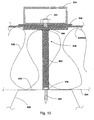
- FIG. 12 Another embodiment of a height-adjustable projection portion 718 is shown in FIG. 12 shown.
- the lower pin portion 762 forms a threaded rod 763 which can be screwed into a sleeve 764 with a mating thread 765 which forms the upper pin portion and carries a support plate 766.
- support plate 766 may be provided with stiffening ribs 767.
- the one of the bolt portions 762; 764 bridged space is again filled by a thermal insulation 736.
- one or more clamping or threaded bolts 722 protrude from the support plate 766, which are carried out from the inside by recesses in the support plate 766 of the projection section 718 and subsequently welded to the support plate 766. In this way, it is ensured that no moisture can penetrate into the interior of the fastening element 712 and into the interior of the building via the threaded screw connections.
- recesses 774 at appropriate locations in the mounting body be provided. Via a lock nut 770, the distance between the two bolt sections and thus the distance between the end face 720 of the projection section 718 and the base section 716 can be adjusted and fixed.
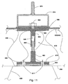
- the threaded bolts 822 are welded to the upper side of the support plate 866, wherein in each case additionally a screw lock 823 is used.
- the support plate 866 On the underside, the support plate 866 carries a fitting, namely a nut 864, for a web portion in the form of a threaded rod 863.
- the base portion 816, i. the mounting plate carries on top also a screw nut 862 for the engagement of the threaded rod 863.
- the gasket 846 on the top and on the bottom of a further gasket 847 is provided.
- Neoprene can again serve as the material for the gasket or pressure supplement, but the material of the sealing gasket can also be used. Basically, the material and / or the geometry of the seal or pressure supplement to the present Adjusted boundary conditions, such as the thickness and / or the compressibility of the clamped layer, so that a maximum and sealing effect is ensured.
- a mounting unit that can be kept in stock for a variety of applications in pre-assembled state.
- the clamping plate 822 is connected to the support plate either materially or in such a way that a joining surface between the clamping bolt and the clamping plate has no passage through the support plate.
- the superstructure body 814 designated 814 is tensioned against the support plate 866 by means of the at least one clamping bolt 822, with the interposition of the sealing sleeve 842 projecting on all sides of the support plate.
- the decisive for the sealing components are therefore already pre-assembled, so that on the site only the roof skin must be cut, the units A, B and C used and the sealing sleeve 842 with the roof skin circumferentially tightly connected, preferably welded or glued, whereby a perfect sealing of the roof can be ensured after the sealing of the sealing collar 842 with the rest of the roof skin, as described with reference to the embodiments of FIGS. 1 to 12 is described. Assembly errors can thus be largely avoided.
- the mounting plate 816 can be combined together with a threaded nut 862 to a universally usable mounting unit C.
- the only variable part B of the assembly group is then the web part 863, which has to be held in different lengths in stock.
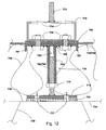
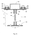
- FIG. 14 An alternative embodiment of the mounting unit is in FIG. 14 shown.
- This mounting unit also has a support plate 966, which has a connection to a web part in the form of a threaded rod 963 on the underside and from the top side a plurality of clamping bolts 922 extend in the form of threaded bolts, which are connected to the support plate either materially or such that a joining surface between the clamping bolt and the clamping plate has no passage through the support plate 966.
- a welded joint between the clamping bolt and the support plate can also find a screw application, in which case a blind hole is formed in the support plate, which is provided with an internal thread.
- a mounting body 914 for the structures seated on the support plate is surrounded by a clamping ring 915.
- the clamping ring 915 is clamped by means of the clamping bolt 922 against the support plate with the interposition of the support plate 966 on all sides superior sealing sleeve, whereby after welding the sealing sleeve 842 with the rest of the roof skin can ensure a perfect seal of the roof, as with reference to the embodiments of the FIGS. 1 to 12 is described.
- the clamping or clamping force of the clamping bolt 922 on the Sealing collar 942 at least on one side via a sealing insert in the form of annular discs 946 and 947 are initiated.
- the web part can again be formed by a threaded rod 963 or tube, wherein the support plate 966 can carry on the underside a nut 964.
- the web portion 963 may be connected to the support plate to a manageable unit, which is then inserted into a receptacle 962 of the base part 916, for example, screwed.
- the mounting body 614 - as in the Figures 11 and 12 shown - be provided with a threaded rod 672, 772, to which an object, such as the Unterertragkonstrutation a photovoltaic system 48, can be attached.
- the length of the threaded rod 672, 772 can be chosen so that it also allows a margin for height adjustment of the object to be fastened in addition to the attachment.
- threaded rod 672, 772 provided with an external thread
- a tube with an internal thread which is provided with a thread corresponding threaded bolt on the fastening object screwed and height adjustable.
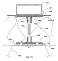
- Fig. 15 shows a further embodiment of a not included in the invention fastening device in which the connection between the projection portion 1018 and mounting body 1014 is not frictionally, for example by a roof seal 1038 or sealing collar 1042 penetrating screw connection, but via a welded connection.
- the protruding section 1018 and the mounting body 1014 have coatings 1076 and 1077, respectively, which can be connected to the seal 1038 or the sealing collar 1042, for example by induction welding or other suitable welding methods.
- appropriate materials are to be selected, which are compatible with the material of the seal 1038 or sealing collar 1042. These include, inter alia, high polymer plastics, especially thermoplastics.
- the projection portion 1018 or the mounting body can be materially connected to the seal 1038, 1042.
- the mounting body 1014 and the protrusion portion 1018 are each positioned so as to be aligned with each other, so that tensile and compressive forces can be transmitted from the mounting body 1014 via the seal 1038 to the protrusion portion.
- the advantage of a cohesive connection is in particular that an introduction of force is ensured in the supporting structure of the building exterior surface, without having to penetrate the seal for fixing the mounting body. This prevents moisture from entering the building interior.
- the web part can again be formed by a threaded rod 1063 or tube, wherein the support plate 1066 can carry a screw nut 1064 on the underside.
- the web portion 1063 may be connected to the support plate to a manageable unit, which is then inserted into a receptacle 1062 of the base part 1016, for example, screwed.
- the fastening device according to the invention can also be used in conjunction with a reversing roof.
- Inverted roofs are generally used in solid construction roof constructions.
- the height of the protrusion portion may be much smaller since the seal is directly on the roof support structure.
- the sealing sleeve is connected directly to the seal located on the roof support structure sealing. Accordingly, the height of the mounting body to enlarge so that it penetrates the insulation located above the seal and possibly other layers.
- the geometry of the fastening device may, inter alia, also be such that the base portion is round and the projection portion has the shape of a cylinder.
- the mounting body can instead of a closed profile, as it is in Fig. 1 and Fig. 2 is shown, consist of two mutually fastened U-profiles.
- fastening device according to the invention is designed in particular for lightweight roof constructions with trapezoidal sheet metal profiles, but this can be readily used for weight savings in solid roof constructions or other warm-roof constructions.
- a profile plate which preferably conforms to the surface of the trapezoidal profile of the flat roof construction over a plurality of areas.
Landscapes
- Engineering & Computer Science (AREA)
- Chemical & Material Sciences (AREA)
- Life Sciences & Earth Sciences (AREA)
- Sustainable Development (AREA)
- Sustainable Energy (AREA)
- Thermal Sciences (AREA)
- Physics & Mathematics (AREA)
- Combustion & Propulsion (AREA)
- Mechanical Engineering (AREA)
- General Engineering & Computer Science (AREA)
- Architecture (AREA)
- Civil Engineering (AREA)
- Structural Engineering (AREA)
- Roof Covering Using Slabs Or Stiff Sheets (AREA)
Description
Die Erfindung betrifft eine Befestigungsvorrichtung für Gegenstände, insbesondere für Aufbauten wie Photovoltaik-Anlagen, auf abgedichteten Gebäudeaußenflächen wie z.B. Flachdachkonstruktionen gemäß dem Oberbegriff des Anspruchs 1.The invention relates to a fastening device for objects, in particular for structures such as photovoltaic systems, on sealed exterior building surfaces such. Flat roof constructions according to the preamble of claim 1.
Gerade größere Gebäude, wie Mehrfamilienhäuser, Industrie- und Gewerbebauten, Bildungseinrichtungen, Hotels etc., bieten sehr gute Voraussetzungen für die Nutzung von Solarenergie, da der spezifische Systempreis, d.h. Kosten pro Quadratmeter Kollektorfläche, wesentlich geringer als bei Kleinanlagen ist. Bei diesen großflächigen Dächern handelt es sich überwiegend um Flachdachkonstruktionen, bei denen als wesentlicher Kostenfaktor die Unterkonstruktion und Montage der Kollektoren Bedeutung erlangt, da die Kollektoren im Vergleich zu Steildächern wegen des Wasserlaufs gegenüber der wasserführenden Schicht der Dachabdichtung aufgeständert und in der Regel noch gegenüber dem horizontalen Flachdach, z.B. mittels eines dreieckförmigen Montagerahmens, in einem Winkel von ca. 30° angestellt und zur Sonne hin ausgerichtet werden.Especially larger buildings, such as multi-family houses, industrial and commercial buildings, educational institutions, hotels, etc., offer very good conditions for the use of solar energy, since the specific system price, i. Cost per square meter of collector surface, much lower than small systems. These large-scale roofs are predominantly flat roof constructions in which the substructure and assembly of the collectors acquire significance as a significant cost factor, since the collectors are raised in comparison to pitched roofs because of the watercourse with respect to the water-bearing layer of the roof seal and usually still with respect to the horizontal Flat roof, eg by means of a triangular mounting frame, be set at an angle of about 30 ° and aligned towards the sun.
Je nach Aufbau des Flachdaches sind verschiedene Unterkonstruktionen für die Montage solcher Photovoltaik-Anlagen bekannt. So werden bei vollflächig belastbaren Flachdächern, z.B. bei Massivflachdächern aus Stahlbeton, die Aufständerung der Photovoltaik-Anlagen mit Hilfe von Betonplatten oder kiesgefüllten Wannen balastiert, um die Anlagen gegen Windkräfte zu sichern.Depending on the structure of the flat roof, various substructures for the installation of such photovoltaic systems known. For example, in solid flat roofs, eg in solid roofs made of reinforced concrete, the elevation of the photovoltaic systems is balastized with the help of concrete slabs or gravel filled pits in order to protect the turbines against wind forces.
Aber selbst bei an sich belastbaren Massivdächern ist es wünschenswert, dass neben der Eigenlast des Daches sowie der Wind- und Schneelast und dem Gewicht der Photovoltaik-Anlagen die Tragreserve des Daches durch schwere Betonplatten nicht unnötig reduziert wird.But even with massive roofs that can be loaded on their own, it is desirable that, in addition to the roof's own weight as well as the wind and snow loads and the weight of the photovoltaic systems, the load bearing capacity of the roof is not unnecessarily reduced by heavy concrete slabs.
Für Leichtdachkonstruktionen, wie z.B. für Flachdächer mit einer leichten, biegeweichen Gerippekonstruktion aus Holz, Stahl oder Stahlbeton mit einer oberseitigen Tragschicht aus Holz oder Trapezblechprofilen, eignen sich die von Massivflachdächern bekannten Ballastierungen der Unterkonstruktion aus statischen Gründen meistens nicht.For lightweight roof constructions, such as For flat roofs with a lightweight, flexible framework construction made of wood, steel or reinforced concrete with a top-layer wooden or trapezoidal sheet metal profiles, the ballastings of the substructure known from solid flat roofs are usually unsuitable for static reasons.
Hier kennt man sehr aufwendige und teure Unterkonstruktionen, welche zum Teil die gesamte Dachfläche überspannen und lediglich von den äußeren Gebäudewänden getragen werden. Zur Reduzierung dieser Kosten ist es aber wünschenswert, dass Aufbauten, wie z.B. Photovoltaik-Anlagen, auch bei solchen Leichtdachkonstruktionen von der Dachkonstruktion selbst getragen und gehalten werden können. Die Befestigung der Unterkonstruktion an der Tragkonstruktion des Flachdaches selbst und die damit verbunden Durchdringung der Dachhaut bringt das Problem der Abdichtung mit sich.Here one knows very elaborate and expensive substructures, which span in part the entire roof area and are carried only by the outer building walls. To reduce these costs, however, it is desirable that structures such as e.g. Photovoltaic systems, even in such lightweight roof structures of the roof construction itself can be worn and maintained. The attachment of the substructure to the supporting structure of the flat roof itself and the associated penetration of the roof skin brings the problem of sealing with it.
Ferner haben manche Unterkonstruktionen das Problem, dass sie an die Gebäudeausrichtung gebunden sind. Eine weitere wesentliche Anforderung an solche Unterkonstruktionen für Photovoltaik-Anlagen ist deshalb die Möglichkeit einer flexiblen Ausrichtung der Kollektoren.Furthermore, some substructures have the problem that they are tied to the building orientation. Another essential requirement of such substructures for photovoltaic systems is therefore the possibility of flexible alignment of the collectors.
Aus
Eine Befestigungsvorrichtung gemäß dem Oberbegriff des Patentanspruchs 1 ist aus
Eine Montageeinheit gemäß dem Oberbegriff des Patentanspruchs 11 ist aus
Der Erfindung liegt somit die Aufgabe zu Grunde, eine Befestigungsvorrichtung für Gegenstände auf abgedichteten Gebäudeaußenflächen wie z.B. für Flachdachaufbauten zu schaffen, welche bei möglichst geringer zusätzlicher Belastung eine flexible und ausreichende Befestigung von Gegenständen oder Aufbauten sicherstellt.The invention is therefore based on the object, an attachment device for objects on sealed exterior building surfaces such. to create for flat roof structures, which ensures a flexible and sufficient attachment of objects or structures with the least possible additional burden.
Diese Aufgabe wird durch die Merkmale des Anspruchs 1 gelöst.This object is solved by the features of claim 1.
Erfindungsgemäß wird der zu befestigende Gegenstand über den Montagekörper und dem Befestigungselement direkt an der Dachkonstruktion befestigt, so dass der Gegenstand bei angreifenden Windkräften oder Ähnlichem ausreichend gesichert ist. Durch die direkte Befestigung an der Tragkonstruktion kann auf eine zusätzliche Ballastierung verzichtet werden, so dass die erfindungsgemäße Befestigungsvorrichtung insbesondere für Leichtdachkonstruktionen, aber auch für Massivdachkonstruktionen mit geringen Tragreserven geeignet ist. Indem die Krafteinwirkung vom Gegenstand direkt auf die Dachkonstruktion überbrückt wird, werden die weiteren Dachschichten, z.B. die Abdichtung und die Wärmedämmung, nicht weiter belastet. Ferner wird über die Abdichtungsmanschette und in Anlehnung an eine sog. "Los- und Festflanschverbindung nach DIN 18195 T9" zwischen Montagekörper und Befestigungselement eine sichere Abdichtung des Durchdringungspunktes gewährleistet, so dass kostspielige Folgeschäden aufgrund von Wassereintritt in das Dach auf einfache und sichere Weise verhindert werden können. Ein weiterer Vorteil der erfindungsgemäßen Befestigungsvorrichtung ist, dass Aufbauten auf dem Flachdach befestigt werden können, ohne dabei den Wasserlauf auf dem Dach zu beeinträchtigen. Denn das Befestigungselement befindet sich im Wesentlichen unterhalb der Abdichtung. Der darüber befindliche Montagekörper stützt den zu befestigenden Gegenstand so, dass zwischen Gegenstand und Abdichtung vorzugsweise ein Freiraum für den Wasserlauf verbleibt. Der Montagekörper selbst kann entsprechend günstig gestaltet sein, dass er den Wasserlauf nicht beeinträchtigt. Ferner lassen sich erfindungsgemäß Aufbauten, z.B. Photovoltaik-Anlagen, unabhängig von der Gebäudeausrichtung oder von der Orientierung der Tragkonstruktion exakt, in der Regel in Richtung Süden, ausrichten.According to the invention, the object to be fastened is fastened directly to the roof structure via the mounting body and the fastening element, so that the object is adequately secured in the case of wind forces or the like. Due to the direct attachment to the support structure can be dispensed with an additional ballast, so that the fastening device according to the invention especially for lightweight roof constructions, but also for Solid roof structures with low reserve capacity is suitable. By bridging the force of the object directly on the roof construction, the other roof layers, such as the seal and the thermal insulation, are not further burdened. Furthermore, a secure sealing of the penetration point is ensured via the sealing collar and based on a so-called. "Loose and fixed flange according to DIN 18195 T9" between the mounting body and fastener so that costly consequential damage due to water ingress into the roof can be prevented in a simple and secure manner can. Another advantage of the fastening device according to the invention is that structures can be mounted on the flat roof, without affecting the watercourse on the roof. Because the fastener is located substantially below the seal. The assembly above it supports the object to be fastened so that between the object and seal preferably a space for the watercourse remains. The mounting body itself can be designed appropriately low that it does not affect the watercourse. Furthermore, according to the invention, structures, for example photovoltaic systems, can be aligned exactly, generally in the direction of the south, independently of the orientation of the building or of the orientation of the supporting structure.
Dabei bildet eine zwischen dem Montagekörper und dem Vorsprungsabschnitt befindliche Abdichtungsmanschette mit der Abdichtung der Gebäudeaußenfläche bzw. des Daches Überlappungsabschnitte und ist mit dieser dichtend verbindbar. Die erfindungsgemäße Befestigungsvorrichtung eignet sich somit nicht nur für Neubauten, sondern kann auch nachträglich ohne großen Aufwand auf bereits bestehenden Flachdächern montiert werden, indem das über der Tragkonstruktion befindliche Schichtenpaket (Wärmedämmung, Abdichtung, u.ä.) nur punktuell zur Einbringung des Befestigungselements geöffnet wird und anschließend mittels Abdichtungsmanschette und Los- und Festflanschverbindung zwischen Montagekörper und Befestigungselement wieder dicht verschlossen wird.In this case, a sealing collar located between the mounting body and the protruding section forms overlapping sections with the sealing of the building exterior surface or the roof and can be sealingly connected thereto. The fastening device according to the invention is thus not only suitable for new buildings, but can also be retrofitted without much effort on existing flat roofs by the over the support structure layer package located (insulation, sealing, etc.) is only selectively opened to the introduction of the fastener and then sealed again by means of sealing sleeve and loose and fixed flange connection between the mounting body and fastener.
Es hat sich gezeigt, dass der Basisabschnitt des Befestigungselements bei Warmdächern direkt auf die auf der Tragkonstruktion befindliche Dampfsperrschicht montiert werden kann, so dass diese zur Montage der Befestigungsvorrichtung nicht entfernt werden muss.It has been found that the base portion of the fastener can be mounted on hot roofs directly on the support structure located on the vapor barrier layer, so that they need not be removed for mounting the fastening device.
Erfindungsgemäß ist die Abdichtungsmanschette mittels einer Spann-, wie z.B. einer Schraubverbindung zwischen Montagekörper und Vorsprungsabschnitt dicht eingepresst. Eine solche Einklemmung kann in Anlehnung an eine Los- und Festflanschkonstruktion nach DIN 18195 T9 erfolgen. Damit lässt sich auf einfache Weise die Verbindung zwischen Montagekörper und Befestigungselement sicher abdichten. Eine einfache Spannverbindung lässt sich durch eine Schraubverbindung realisieren. Es kann jedoch auch jede andere Spannverbindung gleichermaßen Anwendung finden, beispielsweise eine Spannverbindung mit zumindest einem Spannbolzen, der einerseits mit dem Vorsprungsabschnitt verbunden ist und andererseits mit einer Einrichtung zusammenwirkt, mit der der Montagekörper gegen den Vorsprungsabschnitt spannbar ist.According to the invention, the sealing collar is secured by means of a tightening means, e.g. a screw between the mounting body and projection portion pressed tight. Such an entrapment can take place on the basis of a loose and fixed flange construction according to DIN 18195 T9. This makes it easy to securely seal the connection between the mounting body and fastener. A simple clamping connection can be realized by a screw connection. However, it can equally apply to any other clamping connection, for example, a clamping connection with at least one clamping bolt, which is on the one hand connected to the projection portion and on the other hand cooperates with a device with which the mounting body is clamped against the projection portion.
Die Spann- bzw. Schraubverbindung ist dergestalt, dass wenigstens ein oder mehrere Spann- bzw. Gewindebolzen oder Spann- bzw. Schraubverbindungen zur Befestigung des Montagekörpers entweder materialschlüssig angebracht sind oder derart, dass eine Fügefläche zwischen dem Spannbolzen und dem Vorsprungsabschnitt keinen Durchtritt durch den Vorsprungsabschnitt hat. Dies bedeutet, dass selbst bei Wassereintritt zwischen Montagekörper und Vorsprungsabschnitt keinerlei Feuchtigkeit über die Fügefläche, wie z.B. den Gewindezug durch den Vorsprungsabschnitt in das Dachinnere eintreten kann.The clamping or screw connection is such that at least one or more clamping or threaded bolts or clamping or screw connections are mounted for attaching the mounting body either materially or such that a joining surface between the clamping bolt and the projecting portion does not pass through the projecting portion Has. This means that even with water entering between the mounting body and protrusion portion no moisture on the joining surface, such as the thread can enter through the protruding portion in the roof interior.
Erfindungsgemäß ist dabei nur eine Dichtebene erforderlich. Aufgrund der erfindungsgemäßen Befestigung des Spann- bzw. Gewindebolzens, beispielsweise durch die Anschweißung dicht am Vorsprung, kann kein Niederschlagswasser über den Gewindegang ins Dachschichtenpaket eindringen. Die Dichtung erfolgt somit einzig und allein über eine Klemmung der Dachhaut zwischen dem Montagekörper und dem Vorsprungsabschnitt. Eine zweite Klemmung bzw. eine Montage einer Kappe über dem Montagekörper, wie es beim Stand der Technik der Fall ist, ist nicht notwendig. Dadurch wird auf einfache Weise eine sehr dichte Befestigungsvorrichtung für Dachaufbauten geschaffen.According to the invention only one sealing plane is required. Due to the inventive fastening of the clamping or threaded bolt, for example, by the weld close to the projection, no rainwater can penetrate over the thread into the roof layer package. The seal thus takes place solely and solely via a clamping of the roof skin between the mounting body and the projection section. A second clamping or a mounting of a cap over the mounting body, as is the case in the prior art, is not necessary. As a result, a very tight fastening device for roof structures is created in a simple manner.
Um die erfindungsgemäße Befestigungsvorrichtung für unterschiedlich dicke Schichtenpakete aus Wärmedämmung, Abdichtung, Dampfsperre verwenden zu können, ist der Vorsprungsabschnitt höheneinstellbar. So kann die universelle Befestigungsvorrichtung den jeweiligen Bedingungen vor Ort.angepasst werden. Eine Anpassung bereits bei der Herstellung der Befestigungsvorrichtung entfällt somit.In order to use the fastening device according to the invention for different thickness layer packages of thermal insulation, sealing, vapor barrier, the projection portion is height adjustable. Thus, the universal fastening device can be adapted to the respective conditions on site. An adaptation already in the production of the fastening device is thus eliminated.
Die Höhenverstellung kann auf verschiedene Weise erfolgen. Durch eine besonders einfache Handhabungzeichnet sich ein zweiteiliger Bolzen aus, wovon ein Abschnitt ein Gewinde aufweist, welches sich mit dem Gegengewinde des anderen Bolzenabschnitts verschrauben lässt. So lässt sich durch Drehung der Teile die Lage der beiden Bolzenabschnitte zueinander und somit der Abstand der Stirnfläche des Vorsprungsabschnitts zur Tragkonstruktion auf einfache Weise einstellen und der jeweilige Dicke der Wärmedämmung und der anderen Schichten anpassen.The height adjustment can be done in different ways. By a particularly simple handling is characterized by a two-piece bolt, of which one portion has a thread which can be screwed to the mating thread of the other pin portion. Thus, by rotating the parts, the position of the two bolt sections relative to one another and thus the distance between the end face of the projecting section and the supporting structure can be set in a simple manner and the respective thickness of the thermal insulation and the other layers adapted.
Erfindungsgemäß ist die Befestigungsvorrichtung im vormontierten Zustand mit der zwischen dem Montagekörper und den Vorsprungsabschnitt eingespannten Abdichtungsmanschette an der Tragkonstruktion befestigbar.According to the invention, the fastening device can be fastened to the supporting structure in the preassembled state with the sealing collar clamped between the mounting body and the protruding section.
Um die an sich sichere Abdichtung zwischen Montagekörper und Vorsprungsabschnitt weiter zu erhöhen, kann zwischen Montagekörper und Abdichtungsmanschette und/oder zwischen Vorsprungsabschnitt und Abdichtungsmanschette eine Dichtungs- oder Druckbeilage, wie z.B. eine Neoprenschicht oder -platte zusätzlich vorgesehen sein. Diese Dichtungs- oder Druckbeilage, beispielsweise als Neoprenschicht stellt einen gleichmäßigen Anpressdruck zwischen Montagekörper und Befestigungselement sicher und gleicht etwaige Unebenheiten in der Abdichtungsmanschette aus, so dass eine sichere Abdichtung gewährleistet wird. Als Material für die Dichtungs- oder Druckbeilage kann auch das Material der Abdichtungsmanschette herangezogen werden. Grundsätzlich wird das Material und/oder die Geometrie der Dichtungs- oder Druckbeilage an die vorliegenden Randbedingungen angepasst, wie z.B. an die Dicke und/oder die Kompressibilität der einzuklemmenden Schicht, so dass ein Höchstmaß and Dichtwirkung sichergestellt ist.In order to further increase the inherently secure seal between the mounting body and the projection section, a sealing or pressure supplement, such as a neoprene layer or plate, may additionally be provided between the mounting body and the sealing collar and / or between the projection section and the sealing collar. This seal or pressure supplement, for example, as a neoprene layer ensures a uniform contact pressure between the mounting body and fastener and compensates for any bumps in the sealing sleeve, so that a secure seal is guaranteed. As a material for the seal or pressure supplement and the material of the sealing sleeve can be used. Basically, the material and / or the geometry of the seal or pressure supplement to the present Adjusted boundary conditions, such as the thickness and / or the compressibility of the clamped layer, so that a maximum and sealing effect is ensured.
Montagekörper und Vorsprungsabschnitt lassen sich nicht nur kraftschlüssig, z.B. über eine Schraubverbindung, miteinander verbinden, sondern auch stoffschlüssig, z.B. durch geeignete Schweißverfahren, insbesondere Wärmeschweißverfahren oder Induktionsschweißverfahren, oder durch Kleben. Wenn die Verbindung durch ein Schweißverfahren erfolgt, weisen der Montagekörper und der Vorsprungsabschnitt an geeigneten Stellen Beschichtungen auf, so dass sich diese jeweils mit der Abdichtung oder der Abdichtungsmanschette verschweißen lassen und über die Abdichtung bzw. die Abdichtungsmanschette miteinander verbunden sind. Dabei sind für die Beschichtung des Montagekörpers und des Vorsprungsabschnitts entsprechende mit dem Material der Abdichtung bzw. der Abdichtungsmanschette kompatible Materialien auszuwählen.Mounting body and projection portion can not only be frictionally, e.g. connect via a screw connection with each other, but also cohesively, e.g. by suitable welding methods, in particular heat welding or induction welding, or by gluing. When joined by a welding process, the mounting body and the protrusion portion have coatings at appropriate locations so that they can be welded respectively to the seal or the sealing collar and connected to each other via the seal or the sealing collar. In this case, appropriate materials compatible with the material of the seal or of the sealing sleeve are to be selected for the coating of the mounting body and of the protruding section.
Die Höhe des Vorsprungsabschnitts kann so gewählt sein, dass die Stirnfläche des Vorsprungsabschnitts bündig mit der Abdichtung ist. Um jedoch zu vermeiden, dass auf dem Dach stehendes Wasser direkt auf den Verbindungsabschnitt zwischen Montagekörper und Befestigungselement drückt, kann die Höhe des Vorsprungsabschnitts des Befestigungselements vorzugsweise aber auch so gewählt werden, dass er über die Abdichtung hervorsteht, so dass das Niveau des Verbindungsabschnitts in der Regel über der wasserführenden Schicht der Dachabdichtung liegt.The height of the protrusion portion may be selected so that the end surface of the protrusion portion is flush with the seal. However, in order to avoid that water standing on the roof presses directly on the connecting portion between the mounting body and fastener, the height of the protruding portion of the fastener may preferably be selected so that it protrudes beyond the seal, so that the level of the connecting portion in the Usually located above the water-bearing layer of the roof waterproofing.
Zur dichten Verbindung zwischen Abdichtungsmanschette und Abdichtung können beide miteinander verschweißt oder dicht verklebt werden. Eine solche Vorgehensweise hat sich bei Reparaturarbeiten an Flachdächern gut bewährt, insbesondere wenn als Material für die Abdichtungsmanschette das gleiche Material wie bei der Abdichtung verwendet wird oder zumindest ein verträgliches Material, welches sich mit dem der Abdichtung dichtend verbinden lässt. Als besonders geeignet haben sich z.B. ein- oder mehrlagige bituminöse oder Kunststoffschichten erwiesen.For tight connection between sealing sleeve and seal both can be welded together or tightly glued. Such an approach has is well proven in repair work on flat roofs, especially if the material used for the sealing sleeve the same material as in the seal or at least a compatible material which can be sealingly connected to the seal. For example, mono- or multilayer bituminous or plastic layers have proven to be particularly suitable.
Der Montagekörper und/oder das Befestigungselement ist vorteilhafterweise aus Edelstahl, z.B. V2A hergestellt, wodurch neben einer ausreichenden Festigkeit eine gute Korrosionsbeständigkeit bereitgestellt wird.The mounting body and / or the fastening element is advantageously made of stainless steel, e.g. V2A produced, which in addition to a sufficient strength, a good corrosion resistance is provided.
Wenn im Basisabschnitt in vorbestimmten Abständen bzw. mit vorbestimmten Lochmuster Bohrungen vorgesehen werden, kann die erfindungsgemäße Befestigungsvorrichtung für verschiedenste Dachkonstruktionen, insbesondere bei Trapezblechdächern mit unterschiedlich breiten und/oder beabstandeten Obergurten bei einfacher Montagehandhabung verwendet werden. Aufgrund des bestehenden Lochmusters wird die Montage stark vereinfacht. Dennoch ist aufgrund der im Vergleich zum Vorsprungsabschnitt vergrößerten Fläche des Basisabschnitts dafür gesorgt, dass immer die eine oder andere Bohrung in Deckung mit einem Obergurt und mit hoher Wahrscheinlichkeit sogar mit mehreren Obergurten des Trapezbleches kommt, so dass ein Standardbefestigungselement geschaffen wird, welches für verschiedenste Trapezblechdächer geeignet ist. Aufgrund der quasi punktuellen Befestigung der Dachaufbauten über dem Montagekörper ist das Befestigungspunktmuster nicht mehr mit der Geometrie des Flachsdachs und nicht mehr an die Ausrichtung der Flachdachkonstruktion gekoppelt. Dies ist insbesondere bei Photovoltaik-Anlagen von Bedeutung, weil diese dann unabhängig von der Gebäuderichtung vorzugsweise in Richtung Süden ausgerichtet werden können.If bores are provided in the base section at predetermined intervals or with predetermined hole patterns, the fastening device according to the invention can be used for a wide variety of roof structures, in particular with trapezoidal sheet metal roofs with differently wide and / or spaced upper belts with simple assembly handling. Due to the existing hole pattern assembly is greatly simplified. Nevertheless, due to the enlarged compared to the projecting portion surface of the base portion ensured that always one or the other bore in coincidence with a top chord and with high probability even with multiple top chords of the trapezoidal sheet comes, so that a standard fastener is created, which is suitable for a variety of trapezoidal roofs suitable is. Due to the quasi-point attachment of the roof structures on the mounting body, the attachment point pattern is no longer coupled with the geometry of the flax roof and no longer to the orientation of the flat roof construction. This is especially important for photovoltaic systems, because these then independent of the building direction can be aligned preferably to the south.
Je größer die Fläche des Basisabschnitts ist, desto breiter ist das Einsatzgebiet. Die Fläche des Basisabschnitts wird vorzugsweise an die Tragkonstruktion des Gebäudeaußenfläche bzw. des Flachdachs angepasst. Sie kann in bestimmten Anwendungsfällen auf die Grundfläche eines Distanzbolzens beschränkt sein, der dann gleichzeitig den Vorsprungsabschnitt bildet.The larger the area of the base section, the broader the field of application. The surface of the base portion is preferably adapted to the supporting structure of the building exterior surface or the flat roof. It may be limited in certain applications to the base of a spacer bolt, which then forms the projection portion at the same time.
Zur Sicherstellung einer durchgehenden Wärmedämmung kann der durch den Vorsprungsabschnitt gebildete bzw. von diesem überbrückte Hohlraum mit Dämmmaterial, z.B. mit dem Dämmmaterial, das vor dem Einbringen des Befestigungselements aus dem Dach entfernt worden ist, ausgefüllt werden.To ensure continuous thermal insulation, the cavity formed by or bridged by the projecting portion can be insulated with insulating material, e.g. with the insulating material that has been removed before the introduction of the fastener from the roof, filled.
Ferner kann die erfindungsgemäße Befestigungsvorrichtung in Verbindung mit allen gängigen Tragkonstruktionen, z.B. Beton-, Stahl, Holz-, Trapezblechkonstruktionen und andere, verwendet werden, so dass es sich um eine sehr flexible einsetzbare Vorrichtung handelt.Furthermore, the fastening device according to the invention can be used in conjunction with all common supporting structures, such as concrete, steel, wood, Trapezblechblechkonstruktionen and others, so that it is a very flexible usable device.
Die Fixierung der Lage der beiden Bolzenabschnitte zueinander kann vorzugsweise über eine Kontermutter erfolgen.The fixation of the position of the two bolt sections to one another can preferably take place via a lock nut.
Ferner kann vorzugsweise zwischen dem Basisabschnitt und der Tragkonstruktion ein Isolierabschnitt angeordnet sein, welcher die Befestigungsvorrichtung von der Tragkonstruktion der Gebäudeaußenfläche thermisch entkoppelt, so dass keine Wärme bzw. Kälte über die Befestigungsvorrichtung in das Gebäudeinnere geleitet wird.Furthermore, an insulating section can preferably be arranged between the base section and the supporting structure, which thermally decouples the fastening device from the supporting structure of the building exterior surface, so that no heat or cold is conducted via the fastening device into the building interior.
Damit die Lagerhaltung auch dann einfach gehalten werden kann, wenn Befestigungsvorrichtungen für unterschiedlichste Dachkonstruktionen, insbesondere unterschiedlichster Dicken, in kürzester Zeit bereit gestellt werden sollen, wird das Kernstück der Befestigungsvorrichtung zu einer Montageeinheit zusammengefasst, die Gegenstand der nebengeordneten Ansprüche ist.Thus, the storage can be kept simple even when fastening devices for a variety of roof structures, especially different thicknesses to be provided in a very short time, the core of the fastening device is combined to form a mounting unit, which is the subject of the independent claims.
Diese Montageeinheit ist in der Weise vormontiert, dass die Abdichtungsmanschette mit vorbestimmtem Zuschnitt bereits fest und ringsum abgedichtet eingespannt ist. Zur Montage werden diese vormontierten Montageeinheiten in der erforderlichen Anzahl auf die Baustelle gebracht und dort mit variablen Stegteilen und/oder Montageplatten zusammengestellt. Auch die Montageplatten können einheitlich für alle Einsatzgebiete ausgebildet werden, so dass lediglich noch die Stegteile variabel gehalten werden müssen. Die Stegteile sind dementsprechend in unterschiedlichen Längen vorzuhalten.This mounting unit is pre-assembled in such a way that the sealing collar with a predetermined blank is already firmly clamped and sealed all around. For mounting these pre-assembled mounting units in the required number on the Bringing construction site and assembled there with variable web parts and / or mounting plates. The mounting plates can be uniformly formed for all applications, so that only the web parts must be kept variable. The web parts are therefore vorzuhalten in different lengths.
Die Stegteile können jedoch auch entweder mit der Stützplatte oder mit der Montageplatte zu einer handhabbaren Einheit vormontiert sein.However, the web parts can also be pre-assembled with either the support plate or with the mounting plate to a manageable unit.
Auch bei der Montageeinheit kann die Klemm- bzw. Spannkraft des zumindest einen Spannbolzens auf die Abdichtungsmanschette zumindest auf einer Seite über eine Abdichtungsbeilage eingeleitet werden.Also in the assembly unit, the clamping or clamping force of the at least one clamping bolt can be introduced to the sealing sleeve on at least one side via a sealing shim.
Das Stegteil kann von einem Gewindestab oder -rohr gebildet sein, wobei dann die Stützplatte unterseitig entweder eine Schraubmutter oder einen Gewindebolzen trägt.The web portion may be formed by a threaded rod or tube, in which case the support plate carries either a screw nut or a threaded bolt on the underside.
Die als Einheit handhabbare Montageeinheit kann auch um das Stegteil und sogar um die Montageplatte erweitert werden.The assembly unit which can be handled as a unit can also be expanded by the web part and even by the mounting plate.
Nachstehend werden anhand schematischer Zeichnungen vorteilhafte Ausführungsformen der Erfindung näher beschrieben. Es zeigen:
-
Fig. 1 eine perspektivische Ansicht einer Befestigungsvorrichtung nach einer ersten nicht von der Erfindung umfassten Ausführungsform; -
Fig. 2 eine Querschnittsansicht einer Befestigungsvorrichtung nach der ersten nicht von der Erfindung umfassten Ausführungsform; -
Fig. 3 die Detailansicht III inFig. 2 -
Fig. 4 eine Draufsicht einer Befestigungsvorrichtung nach der ersten nicht von der Erfindung umfassten Ausführungsform; -
Fig. 5 eine Draufsicht einer auf dem Dach montierten Befestigungsvorrichtung nach der ersten nicht von der Erfindung umfassten Ausführungsform; -
Fig. 6 eine perspektivische Ansicht einer Befestigungsvorrichtung nach einer zweiten nicht von der Erfindung umfassten Ausführungsform; -
Fig. 7 eine perspektivische Ansicht einer Befestigungsvorrichtung nach einer dritten nicht von der Erfindung umfassten Ausführungsform; -
Fig. 8 eine perspektivische Ansicht einer Befestigungsvorrichtung nach einer vierten nicht von der Erfindung umfassten Ausführungsform; -
Fig. 9 einen schematischen Schnitt einer Befestigungsvorrichtung nach einer fünften nicht von der Erfindung umfassten Ausführungsform; -
Fig 10 eine derFig. 9 entsprechende Ansicht einer sechsten nicht von der Erfindung umfassten Ausführungsform der Befestigungsvorrichtung; -
Fig. 11 eine derFig. 9 entsprechende Ansicht einer erfindungsgemäßen siebten Ausführungsform; -
Fig. 12 eine derFig. 9 entsprechende Ansicht einer erfindungsgemäßen achten Ausführungsform der Befestigungsvorrichtung; und -
Fig. 13 eine derFig. 9 entsprechende Ansicht einer erfindungsgemäßen neunten Ausführungsform der Befestigungsvorrichtung; -
Fig. 14 eine derFig. 9 entsprechende Ansicht der erfindungsgemäßen zehnten Ausführungsform der Befestigungsvorrichtung; und -
Fig. 15 eine derFig. 9 entsprechende Ansicht der elften nicht von der Erfindung umfassten Ausführungsform der Befestigungsvorrichtung.
-
Fig. 1 a perspective view of a fastening device according to a first embodiment not embraced by the invention; -
Fig. 2 a cross-sectional view of a fastening device according to the first embodiment not embraced by the invention; -
Fig. 3 the detailed view III inFig. 2 -
Fig. 4 a plan view of a fastening device according to the first embodiment not embraced by the invention; -
Fig. 5 a plan view of a roof-mounted fastening device according to the first embodiment not embraced by the invention; -
Fig. 6 a perspective view of a fastening device according to a second embodiment not embraced by the invention; -
Fig. 7 a perspective view of a fastening device according to a third embodiment not embraced by the invention; -
Fig. 8 a perspective view of a fastening device according to a fourth embodiment not embraced by the invention; -
Fig. 9 a schematic section of a fastening device according to a fifth embodiment not embraced by the invention; -
FIG. 10 one of theFig. 9 corresponding view of a sixth not embraced by the invention embodiment of the fastening device; -
Fig. 11 one of theFig. 9 corresponding view of a seventh embodiment according to the invention; -
Fig. 12 one of theFig. 9 corresponding view of an eighth embodiment of the fastening device according to the invention; and -
Fig. 13 one of theFig. 9 corresponding view of a ninth embodiment of the fastening device according to the invention; -
Fig. 14 one of theFig. 9 corresponding view of the tenth embodiment of the fastening device according to the invention; and -
Fig. 15 one of theFig. 9 corresponding view of the eleventh not embraced by the invention embodiment of the fastening device.
- Die Tragkonstruktion wird
von einem Trapezblech 28 gebildet, welches von einer nicht gezeigten Gerippekonstruktion aus Holz, Stahl oder Stahlbeton getragen wird. Der Querschnitt des Trapezbleches 28 besteht aus abwechselnd nach oben bzw. unten offenen Trapezen, welche horizontale obere Flächen,sogenannte Obergurte 30, und horizontale untere Flächen,sogenannte Untergurte 32, bilden.Über dem Trapezblech 28 befindet sicheine Dampfsperre 34, welche flächig aufden Obergurten 30 aufliegt bzw. verklebt ist.Die Dampfsperre 34 ist eine Schicht oder eine Folie, die das Durchdringen von Wasserdampf verhindert. Hierzu werden vor allem Folien mit Metällbeschichtungen, aus Kunststoff oder sonstigen geeigneten Materialien verwendet.Die Dampfsperre 34 sorgt dafür, dass sich in der darüberliegenden Wärmedämmung 36 kein Kondensat niederschlägt. Für dieWärmedämmung 36 können künstliche (Polystyrol, Polyurethan, Polyester, etc.), mineralische (Schaumglas, Glasswolle, etc.) oder natürliche (Zellulose, Hanf, Holzfasern, etc.) Materialen verwendet werden. Über der Wärmedämmung 36 befindet sich dieAbdichtung 38, welche verhindert, dass Feuchtigkeit in das Gebäude eindringt und hierdurch teure Schäden in der Dachkonstruktion selbst oder im Gebäudeinneren entstehen. In der Regel werden dazu Kunststofffolien oder bituminöse Abdichtungsbahnen verwendet. Zusätzlich können noch weitere - inFig. 2 nicht gezeigte - Schichten wie eine Gefälleschicht, eine Trenn- und Ausgleichsschicht, eine Dampfdruckausgleichs- und Trennschicht und eine Bekiesung als Oberflächenschutz vorgesehen sein.
- The support structure is formed by a
trapezoidal sheet 28, which is supported by a skeleton construction, not shown, made of wood, steel or reinforced concrete. The cross-section of thetrapezoidal sheet 28 consists of alternately upwardly and downwardly open trapezoids, which form horizontal upper surfaces, so-calledupper belts 30, and horizontal lower surfaces, so-calledlower belts 32. Above thetrapezoidal sheet 28 is avapor barrier 34, which flat on the Upper straps 30 rests or is glued. Thevapor barrier 34 is a layer or film that prevents the penetration of water vapor. For this purpose, especially films with Metällbeschichtungen, plastic or other suitable materials are used. Thevapor barrier 34 ensures that no condensation condenses in the overlyingthermal insulation 36. For thethermal insulation 36 can be used artificial (polystyrene, polyurethane, polyester, etc.), mineral (foam glass, glass wool, etc.) or natural (cellulose, hemp, wood fibers, etc.) materials. Above thethermal insulation 36 is theseal 38, which prevents moisture from entering the building, causing expensive damage to the roof structure itself or to the interior of the building. As a rule, plastic films or bituminous waterproofing membranes are used for this purpose. In addition, other - inFig. 2 layers not shown, such as a gradient layer, a release and leveling layer, a vapor pressure equalizing and separating layer, and a coating for surface protection.
Der Basisabschnitt 16 des Befestigungselements 12 wird an den Obergurten 30 und über der Dampfsperre 34 mit Befestigungselementen 40, z.B. Kippdübeln oder Ähnlichem, befestigt. Die Höhe H des Vorsprungsabschnitts 18 ist so gewählt, dass sie größer als die Höhe WD der Wärmedämmung 36 und der vergleichsweise dünnen Abdichtung 38 zusammen ist, so dass die Stirnfläche 20 des Vorsprungsabschnitts 18 über die Abdichtung 38 hervorsteht. Über die Stirnfläche 20 des Vorsprungsabschnitts 18 wird eine Abdichtungsmanschette 42 so angeordnet, dass sie mit der umgebenden Abdichtung 38 des Daches Überlappungsabschnitte 44 bildet. An den Überlappungsabschnitten 44 ist die Abdichtungsmanschette 42 mit der Abdichtung 38, z.B. durch Verschweißen oder Dichtkleben, dichtend verbunden. Als Material für die Abdichtungsmanschette 42 kann das gleiche Material wie bei der Abdichtung 38, z.B. eine zweilagige bituminöse oder eine einlagige Kunststoffschicht, verwendet werden. Über der Abdichtungsmanschette 42 kann eine Neoprenplatte 46, kunststoffplatte oder Ähnliches angeordnet werden, welche zusammen mit der Abdichtungsmanschette durch den darüber befestigten Montagekörper 14 dichtend verspannt wird. Dabei sind in der Abdichtungsmanschette 42 und in der Neoprenplatte 46 Ausnehmungen für die Schraubverbindung zwischen Montagekörper 14 und Befestigungselement 12 vorgesehen.The
Wenn die Befestigungsvorrichtung nicht erst nachträglich auf einem bereits dem Flachdach angebracht wird, sondern schon beim Neubau berücksichtigt wird, hat man die Möglichkeit, das Befestigungselement 12 an der Tragkonstruktion 28 zu befestigen, bevor die Wärmedämmung 36 und die Abdichtung 38 auf dem Flachdach verlegt werden. Da in diesem Fall die Abdichtung 38 nicht zu erst geöffnet und anschließend mittels Abdichtungsmanschette 42 wieder dicht verschlossen werden muss, kann die neu verlegte Abdichtung 38 selbst zwischen Montagekörper 14 und Vorsprungsabschnitt 18 eingespannt werden. Der Aufbau ist wie in
Zur Befestigung des Montagekörpers 14 stehen aus der Stirnfläche 20 ein oder mehrerer Spann- bzw. Gewindebolzen 22 heraus, welche von innen durch Ausnehmungen in der Stirnflächenwandung des Vorsprungsabschnitts 18 durchgeführt und anschließend mit dem Vorsprungsabschnitt verschweißt sind (siehe
In der Draufsicht der
Eine rechteckige Grundfläche, deren eine Seitenlänge wenigstens 400mm beträgt, für den Basisabschnitt und 200x200 mm für die Stirnfläche 20 des Vorsprungsabschnitts 18 haben sich als praktikable Abmessungen gezeigt. Freilich ist der erfindungsgemäße Gegenstand nicht auf diese Abmessungen begrenzt.A rectangular base whose one side length is at least 400mm for the base portion and 200x200mm for the
Zur Vermeidung von Korrosion und Einhaltung von Brandschutzrichtlinien ist es sinnvoll, die Befestigungsvorrichtung 10, d.h. das Befestigungselement 12 und der Montagekörper 14, aus Edelstahl, z.B. aus V2A, verzinkten Stahl oder Verbundbaustoffe zu fertigen.To avoid corrosion and fire safety compliance, it is useful to have the
Die Befestigungsvorrichtung 10 kann nicht nur bei Neubauflachdächern, sondern auch nachträglich bei bereits bestehenden Flachdächern installiert werden. Bei der nachträglichen Montage wird, wie aus
Es ist aber auch möglich, aus der Abdichtung 38 und Wärmedämmung 36 Material in der Größe der Grundfläche des Basisabschnitts 16 zunächst zu entnehmen und nach dem Einbringen des Befestigungselements wieder einzusetzen und abzudichten.However, it is also possible to first remove material from the
In den
Das in
In den
Bei der Variante nach
Die Grundfläche des Basisabschnitts 16, 216, 316 wird vorzugsweise so gewählt, dass sie mit dem Lochmuster 17, 117, 317 eine ausreichend große Fläche abdeckt, so dass ausreichend viele Löcher 17, 117, 317 über tragenden Bereichen der Tragkonstruktion der abgedichteten Gebäudeaußenfläche zu liegen kommen. Für manche Anwendungen, d.h. für die Montage an tragfähigeren Konstruktionen, kann die Grundfläche auch verkleinert werden, was anhand der folgenden Ausführungsformen nach den
Gemäß
Zur thermischen Entkopplung der Befestigungsvorrichtung 410 und der Tragkonstruktion 428 der Gebäudeaußenfläche kann zusätzlich zwischen dem Basisabschnitt 416 und der Tragkonstruktion 428, vorzugsweise zwischen dem Basisabschnitt 416 und der Dampfsperre 434, ein Isolierabschnitt 433 aus einem Material mit möglichst geringer Wärmeleitfähigkeit z.B. aus Hartkunststoff oder anderen geeigneten Materialien angeordnet werden. Damit stellt die erfindungsgemäße Vorrichtung eine Befestigung von Gegenständen bei gleichzeitiger Wasser- oder Wärmedichtheit der Gebäudeaußenfläche sicher. Der Isolierabschnitt 433 kann vorteilhafterweise aus dem Material der Dachhaut bestehen. In diesem Fall kann bei nachträglich montierten Befestigungsvorrichtungen das zuvor aus der Dachhaut herausgeschnittene Dachhautstück verwendet werden.For thermal decoupling of the fastening device 410 and the supporting
Für noch stabilere Bauwerk-Tragkonstruktionen kann die Variante nach
Eine weitere Ausführungsform eines höhenverstellbaren Vorsprungsabschnitts 718 ist in
Dies ermöglicht den Einsatz der erfindungsgemäßen Befestigungsvorrichtung bei Gebäudeaußenflächen mit unterschiedlich dicken Schichten zwischen der Tragkonstruktion 728 und der Abdichtung 746.This allows the use of the fastening device according to the invention in building exterior surfaces with different thickness layers between the
Weiter Ausführungsformen der Erfindung sind in den
Abweichend von den zuvor beschriebenen Varianten sind die Gewindebolzen 822 an die Oberseite der Stützplatte 866 geschweißt, wobei zusätzlich jeweils eine Schraubensicherung 823 Verwendung findet. Unterseitig trägt die Stützplatte 866 ein Anschlussstück, nämlich eine Schraubenmutter 864, für ein Stegteil in Form einer Gewindestange 863. Der Basisabschnitt 816, d.h. die Montageplatte trägt auf oberseitig ebenfalls eine Schraubmutter 862 für den Eingriff der Gewindestange 863. Schließlich ist zusätzlich zu der Dichtungsbeilage 846 auf der Oberseite auch auf der Unterseite eine weitere Dichtungsbeilage 847 vorgesehen.Deviating from the variants described above, the threaded
Als Material für die Dichtungs- oder Druckbeilage kann wieder Neopren dienen, aber es kann auch das Material der Abdichtungsmanschette herangezogen werden. Grundsätzlich wird das Material und/oder die Geometrie der Dichtungs- oder Druckbeilage an die vorliegenden Randbedingungen angepasst, wie z.B. an die Dicke und/oder die Kompressibilität der einzuklemmenden Schicht, so dass ein Höchstmaß and Dichtwirkung sichergestellt ist.Neoprene can again serve as the material for the gasket or pressure supplement, but the material of the sealing gasket can also be used. Basically, the material and / or the geometry of the seal or pressure supplement to the present Adjusted boundary conditions, such as the thickness and / or the compressibility of the clamped layer, so that a maximum and sealing effect is ensured.
Für den Anwendungsfall einer nachträglich auf einem Flachdach zu montierenden Befestigungsvorrichtung ist mit dem Bezugszeichen A eine Montageeinheit bezeichnet, die für unterschiedlichste Anwendungen in vormontiertem Zustand auf Lager gehalten werden kann. Dabei trägt also die Stützplatte 866 unterseitig einen Anschluss zum Stegteil 863. Der Spannbolzen 822 ist mit der Stützplatte entweder materialschlüssig oder derart verbunden, dass eine Fügefläche zwischen dem Spannbolzen und der Spannplatte keinen Durchtritt durch die Stützplatte hat. Der mit 814 bezeichnete Montagekörper 814 für die Aufbauten wird unter Zwischenschaltung der die Stützplatte allseitig überragenden Abdichtungsmanschette 842 mittels des zumindest einen Spannbolzens 822 gegen die Stützplatte 866 gespannt. Die für die Abdichtung entscheidenden Bauteile sind demnach bereits vormontiert, so dass auf der Baustelle lediglich noch die Dachhaut aufgeschnitten werden muss, die Einheiten A, B und C eingesetzt und die Abdichtungsmanschette 842 mit der Dachhaut umlaufend dicht verbunden, vorzugsweise verschweißt oder verklebt werden muss, wodurch sich nach dem Verschweißen der Abdichtungsmanschette 842 mit der restlichen Dachhaut eine vollkommene Abdichtung des Dachs sicherstellen lässt, wie dies unter Bezug auf die Ausführungsformen der
Auch die Montageplatte 816 kann zusammen mit einer Gewindemutter 862 zu einer universell verwendbaren Montageeinheit C zusammengefasst sein. Einziges variables Teil B der Montagegruppe ist dann das Stegteil 863, das in verschiedenen Längen auf Lager gehalten werden muss.The mounting
Es können auch die Einheiten A und B oder die Einheiten B und C zu einheitlich handhabbaren Einheiten zusammengefasst werden.It is also possible to combine units A and B or units B and C into unitary units.
Eine alternative Ausgestaltung der Montageeinheit ist in
Auch diese Montageeinheit hat eine Stützplatte 966, welche unterseitig einen Anschluss zu einem Stegteil in Form einer Gewindestange 963 hat und von der sich oberseitig mehrere Spannbolzen 922 in Form von Gewindebolzen weg erstrecken, die mit der Stützplatte entweder materialschlüssig oder derart verbunden sind, dass eine Fügefläche zwischen dem Spannbolzen und der Spannplatte keinen Durchtritt durch die Stützplatte 966 hat. Anstelle einer Schweißverbindung zwischen Spannbolzen und Stützplatte kann auch eine Schraubverbindung Anwendung finden, wobei in diesem Fall in der Stützplatte ein Sackloch ausgebildet wird, das mit einem Innengewinde versehen wird.This mounting unit also has a
Im Unterschied zur Ausgestaltung nach
Auch bei dieser Variante kann die Klemm- bzw. Spannkraft der Spannbolzen 922 auf die Abdichtungsmanschette 942 zumindest auf einer Seite über eine Abdichtungsbeilage in Form von Ringscheiben 946 und 947 eingeleitet werden.Also in this variant, the clamping or clamping force of the
Das Stegteil kann wieder von einem Gewindestab 963 oder -rohr gebildet sein, wobei die Stützplatte 966 unterseitig eine Schraubmutter 964 tragen kann.The web part can again be formed by a threaded
Auch hier kann das Stegteil 963 mit der Stützplatte zu einer handhabbaren Einheit verbunden sein, die dann in eine Aufnahme 962 des Basisteils 916 eingesetzt, beispielsweise eingeschraubt wird.Again, the
Schließlich können auch alle Einheiten A, B und C zu einer vormontierten Montageeinheit zusammengefasst werden.Finally, all units A, B and C can be combined to form a preassembled mounting unit.
Freilich sind auch andere aus dem Stand der Technik bekannte Maßnahmen zur Höhen- und Längenverstellung, z.B. eine Hülsen-Stift-Anordnung mit einer Klemmschraube etc., auf den Anmeldungsgegenstand anwendbar.Of course, other height and length adjustment measures known in the art, e.g. a sleeve-pin assembly with a clamping screw, etc., applicable to the subject of the application.
Anstelle von Bohrungen 26 (siehe
Freilich kann anstelle der mit einem Außengewinde versehenen Gewindestange 672, 772 auch ein Rohr mit einem Innengewinde vorgesehen werden, welches mit einem entsprechenden Gewindebolzen am Befestigungsgegenstand verschraubbar und höhenjustierbar ist.Of course, instead of the threaded
Durch Aufschmelzen der Beschichtungen 1076, 1077 können der Vorsprungsabschnitt 1018 bzw. der Montagekörper stoffschlüssig mit der Abdichtung 1038, 1042 verbunden werden. Dabei ist zu beachten, dass der Montagekörper 1014 und der Vorsprungsabschnitt 1018 jeweils so positioniert werden, dass sie miteinander fluchten, so dass Zug- und Druckkräfte vom Montagekörper 1014 über die Abdichtung 1038 zum Vorsprungsabschnitt übertragen werden können.By melting the
Je nach Anwendungsfall und zu erwartende Kräfte, die auf die Befestigungsvorrichtung wirken, ist es auch denkbar, den Montagekörper 1014 und den Vorsprungsabschnitt 1018 jeweils mit der Abdichtung 1038 bzw. mit der Abdichtungsmanschette 1042 zu verkleben.Depending on the application and expected forces, which act on the fastening device, it is also conceivable to glue the mounting
Der Vorteil einer stoffschlüssigen Verbindung liegt insbesondere darin, dass eine Krafteinleitung in die Tragkonstruktion der Gebäudeaußenfläche gewährleistet wird, ohne dabei zur Befestigung des Montagekörpers die Abdichtung durchdringen zu müssen. Dadurch wird verhindert, dass Feuchtigkeit in das Gebäudeinnere gelangt.The advantage of a cohesive connection is in particular that an introduction of force is ensured in the supporting structure of the building exterior surface, without having to penetrate the seal for fixing the mounting body. This prevents moisture from entering the building interior.
Das Stegteil kann wieder von einem Gewindestab 1063 oder -rohr gebildet sein, wobei die Stützplatte 1066 unterseitig eine Schraubmutter 1064 tragen kann.The web part can again be formed by a threaded
Auch hier kann das Stegteil 1063 mit der Stützplatte zu einer handhabbaren Einheit verbunden sein, die dann in eine Aufnahme 1062 des Basisteils 1016 eingesetzt, beispielsweise eingeschraubt wird.Again, the
Es ist auch möglich bei einem Bauwerk die vorstehenden Varianten der Befestigungsvorrichtungen bzw. Befestigungselemente miteinander zu kombinieren.It is also possible in a building to combine the above variants of the fastening devices or fasteners together.
Selbstverständlich sind Abwandlungen von der beschriebenen Ausführungsform möglich, ohne den Grundgedanken der Erfindung zu verlassen.Of course, modifications of the described embodiment are possible without departing from the spirit of the invention.
Beispielweise kann die erfindungsgemäße Befestigungsvorrichtung auch in Verbindung mit einem Umkehrdach eingesetzt werden. Umkehrdächer finden in der Regel Anwendung bei Massivbaudachkonstruktionen. In diesem Fall kann Höhe des Vorsprungsabschnitts wesentlich kleiner bleiben, da sich die Abdichtung unmittelbar auf der Dachtragkonstruktion befindet. Dabei wird die Abdichtungsmanschette direkt mit der auf der Dachtragkonstruktion befindlichen Abdichtung dichtend verbunden. Entsprechend ist die Höhe des Montagekörpers so zu vergrößern, dass diese die über der Abdichtung befindliche Wärmedämmung und ggf. andere Schichten durchdringt.For example, the fastening device according to the invention can also be used in conjunction with a reversing roof. Inverted roofs are generally used in solid construction roof constructions. In this case, the height of the protrusion portion may be much smaller since the seal is directly on the roof support structure. In this case, the sealing sleeve is connected directly to the seal located on the roof support structure sealing. Accordingly, the height of the mounting body to enlarge so that it penetrates the insulation located above the seal and possibly other layers.
Ferner kann die Geometrie der Befestigungsvorrichtung unter anderem auch dergestalt sein, dass der Basisabschnitt rund ist und der Vorsprungsabschnitt die Form eines Zylinders hat.Furthermore, the geometry of the fastening device may, inter alia, also be such that the base portion is round and the projection portion has the shape of a cylinder.
Der Montagekörper kann statt einem geschlossenen Profil, wie es in
Die erfindungsgemäße Befestigungsvorrichtung ist zwar insbesondere für Leichtdachkonstruktionen mit Trapezblechprofilen konzipiert, jedoch lässt sich diese ohne weiteres zur Gewichtsersparnis bei Massivdachkonstruktionen oder anderen Warmdachkonstruktionen verwenden.Although the fastening device according to the invention is designed in particular for lightweight roof constructions with trapezoidal sheet metal profiles, but this can be readily used for weight savings in solid roof constructions or other warm-roof constructions.
Anstelle eines ebenen Basisabschnitts bzw. einer ebenen Montageplatte kann auch eine Profilplatte verwendet werden, die sich an die Oberfläche des Trapezprofils der Flachdachkonstruktion vorzugsweise mehrflächig anschmiegt.Instead of a flat base portion or a flat mounting plate, it is also possible to use a profile plate which preferably conforms to the surface of the trapezoidal profile of the flat roof construction over a plurality of areas.
- 10; 110;...; 101010; 110; ...; 1010
- Befestigungsvorrichtungfastening device
- 12; 112;...; 101212; 112; ...; 1012
- Befestigungselementfastener
- 14; 114;...; 101414; 114; ...; 1014
- Montagekörpermounting body
- 16; 116;...; 101616; 116; ...; 1016
- Basisabschnittbase section
- 17; 117;...; 101717; 117; ...; 1017
- Bohrungendrilling
- 18; 118;...; 101818; 118; ...; 1018
- Vorsprungsabschnittprojecting portion
- 2020
- Stirnflächeface
- 22; 122;...; 92222; 122; ...; 922
- Spann- bzw. GewindebolzenClamping or threaded bolt
- 823; 923823; 923
- SchraubsicherungScrewlock
- 2424
- Bohrungendrilling
- 2626
- Bohrungendrilling
- 28; 428;...; 728; 102828; 428; ...; 728; 1028
- Trapezblechtrapezoidal sheet
- 30; 130;...; 730; 103030; 130; ...; 730; 1030
- Obergurtetop chords
- 3232
- Untergurtelower chords
- 433; 633; 733; 1033433; 633; 733; 1033
- Isolierabschnittinsulating
- 34; 134;...; 734; 103434; 134; ...; 734; 1034
- Dampfsperrevapor barrier
- 36; 436;...; 73636; 436; ...; 736
- Wärmedämmungthermal insulation
- 38; 138;...; 73838; 138; ...; 738
- Abdichtungseal
- 4040
- Kippdübeltoggle bolts
- 42; 142;...; 74242; 142; ...; 742
- Abdichtungsmanschettesealing collar
- 4444
- Überlappungsabschnitteoverlap portions
- 46; 146;...; 74646; 146; ...; 746
- Neoprenplatteneoprene plate
- 746; 846746; 846
- Dichtungsbeilagesealing insert
- 847; 947847; 947
- Dichtungsbeilagesealing insert
- 4848
- Träger einer Photovoltaik-AnlageCarrier of a photovoltaic system
- 5050
- Befestigungselementfastener
- 5252
- Schlitzeslots
- 5454
- Abschnittesections
- 5656
- Abdichtbahnensealing sheets
- 560560
- BohrschraubeBohrschraube
- 362; 462; 562; 662362; 462; 562; 662
- Stehbolzen / unterer BolzenabschnittStud bolt / lower bolt section
- 862, 962862, 962
- Schraubmutternut
- 663; 763663; 763
- Gewindeabschnittthreaded portion
- 664; 764664; 764
- oberer BolzenabschnittUpper bolt section
- 864, 964864, 964
- Schraubmutternut
- 665; 765665; 765
- Gegengewindemating thread
- 366; 466;...; 1066366; 466; ...; 1066
- Stützplattesupport plate
- 767767
- Aussteifungsrippenstiffening
- 770770
- Kontermutterlocknut
- 672; 772672; 772
- Gewindestangethreaded rod
- 774774
- Montageaussparungmounting recess
- 10761076
- Beschichtungcoating
- 10771077
- Beschichtungcoating
- A, B, CA, B, C
- Montageeinheitenassembly units
- HH
- Höhe des BefestigungselementsHeight of the fastener
- WDWD
- Höhe der WärmedämmungHeight of thermal insulation
Claims (9)
- Fastening device (10) for fastening objects (48), in particular for fastening structures such as photovoltaic systems, to sealed outer building surfaces such as, for example, flat roof constructions, having:a mounting body (14) to which the object (48) to be fastened can be fastened; anda fastening element (12) having at least one projecting section (18) and a base section (16); whereinthe base section (16) can be fastened to a supporting structure (28) of the outer building surface and the projecting section (18) can be connected to the mounting body (14),the projecting section (18) is so configured that, on the side remote from the supporting structure (28), it projects to a plane of a seal (38) located on the supporting structure (28) and thereby penetrates the seal (38) and any other layers located between the supporting structure (28) and the seal (38, 42), in particular a heat-insulating layer (36),the fastening device comprises a sealing collar (42) which is arranged between the mounting body (14) and the projecting section (18) and extends beyond the projecting section (18) on all sides, which sealing collar (42) is suitable for forming overlapping sections (44) with the surrounding seal (38) and for being sealingly connected thereto, whereinthe projecting section (18) has at least one clamping or threaded bolt (22) for the fastening of the mounting body (14), which clamping or threaded bolt (22) is connected to the projecting section (18) by material bonding or in such a manner that a joint surface between the clamping bolt (22) and the projecting section (18) has no passage through the projecting section (18);the sealing collar (42) is sealingly clamped between the mounting body (14) and the projecting section (18) by means of the at least one clamping or threaded bolt (22); andthe fastening device (10) can be fastened to the supporting structure (28) in the pre-mounted state with the sealing collar (42) clamped between the mounting body (14) and the projecting section (18);characterised in that the projecting section (618; 718; 818) is adjustable in terms of its height.
- Fastening device (10) according to claim 1, characterised in that a sealing or pressure insert, such as, for example, a neoprene layer or sheet (46), is arranged between the mounting body (14) and the sealing collar (42) and/or between the projecting section (866) and the sealing collar (842).
- Fastening device (10) according to any one of the preceding claims, characterised in that the at least one projecting section (18) is suitable for protruding beyond the seal (38).
- Fastening device (10) according to any one of the preceding claims, characterised in that the sealing collar (42) can be adhesively bonded or welded to the seal (38).
- Fastening device (10) according to any one of the preceding claims, characterised in that the sealing collar (42) is made from the same material as the seal (38) or from a material that is compatible therewith to produce a sealing connection, in particular from a two-layer bitumen or a single-layer plastics material.
- Fastening device (10) according to any one of the preceding claims, characterised in that bores (17) are provided in the base section (16) at predetermined intervals.
- Fastening device (10) according to any one of the preceding claims, characterised in that the base section (16) and the supporting structure (28) can enclose a vapour barrier layer (34).
- Fastening device according to any one of the preceding claims, further characterised by an insulating section (433) of a material having low thermal conductivity, preferably a rigid plastics disc, which can be arranged between the supporting structure (428) and the base section (416) for the purpose of thermal decoupling of the fastening device (410) and the supporting structure (428).
- Fastening device according to any one of the preceding claims, characterised in that the projecting section (818) comprises:a support plate (866) which can be connected to the mounting body (814);an upper connecting section (864), preferably in the form of a screw nut, with which the plate (866) can be connected to a bar member (863), preferably in the form of a threaded rod; anda lower connecting section (862), preferably in the form of a further screw nut, via which the bar member (863) can be connected to the base section (816) and which is connected to the base section (816), whereinthe support plate (866) and the mounting body (814), with the interposition of the sealing collar (846), form a mounting unit (A) which in the pre-mounted state can be connected via the bar member (863) to the base section (816) fastened to the supporting structure (28) of the outer building surface.
Priority Applications (1)
| Application Number | Priority Date | Filing Date | Title |
|---|---|---|---|
| EP07722829.4A EP1992017B1 (en) | 2006-02-16 | 2007-02-15 | Fastening device for fastening objects on sealed outer building surfaces |
Applications Claiming Priority (7)
| Application Number | Priority Date | Filing Date | Title |
|---|---|---|---|
| DE102006007294 | 2006-02-16 | ||
| DE102006013792 | 2006-03-24 | ||
| DE102006022593 | 2006-05-15 | ||
| DE102006022870A DE102006022870A1 (en) | 2006-02-16 | 2006-05-16 | Fastening device for fastening objects e.g. for fastening structures e.g. photovoltaic systems, has installation body attached to fastening object and fastening element is fixed with projection section and base section |
| EP2007000274 | 2007-01-12 | ||
| EP07722829.4A EP1992017B1 (en) | 2006-02-16 | 2007-02-15 | Fastening device for fastening objects on sealed outer building surfaces |
| PCT/EP2007/001323 WO2007093421A2 (en) | 2006-02-16 | 2007-02-15 | Fastening device for fastening objects on sealed outer building surfaces and associated installation unit |
Publications (2)
| Publication Number | Publication Date |
|---|---|
| EP1992017A2 EP1992017A2 (en) | 2008-11-19 |
| EP1992017B1 true EP1992017B1 (en) | 2014-04-16 |
Family
ID=38153446
Family Applications (1)
| Application Number | Title | Priority Date | Filing Date |
|---|---|---|---|
| EP07722829.4A Active EP1992017B1 (en) | 2006-02-16 | 2007-02-15 | Fastening device for fastening objects on sealed outer building surfaces |
Country Status (3)
| Country | Link |
|---|---|
| EP (1) | EP1992017B1 (en) |
| DE (2) | DE112007000413A5 (en) |
| WO (1) | WO2007093421A2 (en) |
Families Citing this family (25)
| Publication number | Priority date | Publication date | Assignee | Title |
|---|---|---|---|---|
| US20110041429A1 (en) † | 2008-02-02 | 2011-02-24 | Renolit Belgium N.V. | Profiles for fixing rigid plates |
| DE102008034409B4 (en) * | 2008-07-23 | 2020-02-06 | Wittenauer Gmbh | Foil penetration element and its use |
| DE202009013602U1 (en) * | 2008-12-05 | 2010-04-15 | Climasol-Solaranlagen Gmbh | mounting system |
| DE102009003165A1 (en) * | 2008-12-05 | 2010-06-17 | Climasol-Solaranlagen Gmbh | Mounting system and method for assembling solar modules |
| US9447988B2 (en) | 2010-01-25 | 2016-09-20 | Rillito Rive Solar, LLC | Roof mount assembly |
| IT1393630B1 (en) * | 2009-03-30 | 2012-05-08 | Marco Pietro Borrini | SYSTEM FOR FIXING PHOTOVOLTAIC MODULES TO A COVERAGE COVER |
| FR2944568B1 (en) * | 2009-04-20 | 2015-08-21 | Arcelormittal Construction France | FIXING PART FOR ASSEMBLING A MODULE, IN PARTICULAR A PHOTOVOLTAIC MODULE, ON A RIBBED ROOF, ASSEMBLY AND USE FOR CARRYING OUT A BUILDING COVER |
| DE202009007326U1 (en) | 2009-05-26 | 2009-10-29 | Schweiger, Thomas | Sliding bearing for fixing a roof support structure |
| ITLI20090007A1 (en) * | 2009-07-02 | 2009-10-01 | Antonino Repici | ULTRA LOCKING SYSTEM FOR PHOTOVOLTAIC PANELS ON COVERS WITH BITUMINOUS OR SYNTHETIC HANDS OR IN STEEL SHEETS OR IN FIBERCEMENT. |
| DE102009033416B3 (en) | 2009-07-16 | 2011-01-13 | Ejot Baubefestigungen Gmbh | Mounting system for attachments |
| DE102010036305A1 (en) * | 2010-07-08 | 2012-01-12 | Sfs Intec Holding Ag | Device for fastening a supporting structure on a flat roof |
| AT12832U1 (en) * | 2011-06-01 | 2012-12-15 | Mage Sunfixings Gmbh | SOLAR ROOF CONNECTION SYSTEM |
| US11022343B2 (en) | 2011-09-02 | 2021-06-01 | Pv Solutions, Llc | Mounting system for photovoltaic arrays |
| JP6144261B2 (en) * | 2011-09-02 | 2017-07-12 | アールテラ、ホールディングス、リミテッド、ライアビリティー、カンパニーRterra Holdings, Llc | Mounting system for photovoltaic array |
| US10008974B2 (en) | 2011-09-02 | 2018-06-26 | Pv Solutions, Llc | Mounting system for photovoltaic arrays |
| WO2013033687A1 (en) | 2011-09-02 | 2013-03-07 | Rtetta Holdings, Llc | System for tracking and allocating renewable energy contributions to a modular renewable energy system |
| GB201209197D0 (en) * | 2012-05-25 | 2012-07-04 | Boyt Paul | Fixing items to building structures |
| US9973142B2 (en) | 2013-03-06 | 2018-05-15 | Vermont Slate and Copper Services, Inc. | Snow fence for a solar panel |
| US9985575B2 (en) | 2014-04-07 | 2018-05-29 | Rillito River Solar, Llc | Height adjustment bracket for roof applications |
| US12107530B2 (en) | 2014-04-07 | 2024-10-01 | EcoFasten Solar, LLC | Height adjustment bracket for roof applications |
| US9431953B2 (en) | 2014-10-31 | 2016-08-30 | Rillito River Solar, Llc | Height adjustment bracket for roof applications |
| WO2016123357A2 (en) | 2015-01-28 | 2016-08-04 | Pv Solutions, Llc | Integrated electrical and mechanical photovoltaic array interconnection system |
| DE102015013086A1 (en) | 2015-10-01 | 2017-04-06 | Jutta Regina Giller | Attic for building |
| US10469023B2 (en) | 2016-09-12 | 2019-11-05 | EcoFasten Solar, LLC | Roof mounting system |
| CN114790799A (en) * | 2022-04-28 | 2022-07-26 | 多维联合集团有限公司 | Wind-resistant clamp, wind-resistant clamp assembly, roof panel assembly and roof system |
Family Cites Families (3)
| Publication number | Priority date | Publication date | Assignee | Title |
|---|---|---|---|---|
| FR2676242B1 (en) | 1991-05-07 | 1997-04-30 | Axter | COVER AND ROOFING ASSEMBLY. |
| US6526701B2 (en) | 2000-07-03 | 2003-03-04 | Vermont Slate & Copper Services, Inc. | Roof mount |
| DE202004005224U1 (en) | 2004-04-02 | 2004-06-24 | Schüco International KG. | Mounting system especially for fixing solar modules onto flat roofs has upper and lower pressure plates with sealing path and has profile adapter at upper pressure plate for moving profile carrier |
-
2007
- 2007-02-15 EP EP07722829.4A patent/EP1992017B1/en active Active
- 2007-02-15 WO PCT/EP2007/001323 patent/WO2007093421A2/en not_active Ceased
- 2007-02-15 DE DE112007000413T patent/DE112007000413A5/en not_active Withdrawn
- 2007-02-15 DE DE202007008846U patent/DE202007008846U1/en not_active Expired - Lifetime
Also Published As
| Publication number | Publication date |
|---|---|
| WO2007093421A2 (en) | 2007-08-23 |
| DE112007000413A5 (en) | 2009-04-16 |
| DE202007008846U1 (en) | 2007-10-31 |
| WO2007093421A3 (en) | 2007-12-21 |
| EP1992017A2 (en) | 2008-11-19 |
Similar Documents
| Publication | Publication Date | Title |
|---|---|---|
| EP1992017B1 (en) | Fastening device for fastening objects on sealed outer building surfaces | |
| DE102006022870A1 (en) | Fastening device for fastening objects e.g. for fastening structures e.g. photovoltaic systems, has installation body attached to fastening object and fastening element is fixed with projection section and base section | |
| EP2174074A1 (en) | Assembly frame for the integrated mounting of photovoltaic modules and solar collectors on buildings | |
| DE2226889A1 (en) | Building system, in particular for the purpose of building, container and vehicle superstructures | |
| DE102008012717A1 (en) | Support device e.g. supporting stand, for fixing of impact points on flat roofs, of building, has support unit with support segments adjusted relative to each other, and base plate and geometry part arranged at respective segments | |
| EP1619727A2 (en) | Means for fastening function groups on flat roofs, particularly solar modules on industry halls | |
| DE20117280U1 (en) | Module for the assembly of one or more photovoltaic and / or other solar elements | |
| DE102008031453A1 (en) | Sandwich-prefabricated roof module for e.g. warehouse, has inclinedly bent region carrying photovoltaic element that is attached to water distribution unit connected with water supply for cleaning and cooling photovoltaic element | |
| EP2312235A2 (en) | Support for photovoltaic modules on flat roofs | |
| EP1375770A2 (en) | Sandwich panel, assembly with two sandwich panels and a half-product for the manufacture of such a sandwich panel | |
| DE102009043808A1 (en) | Mounting system and roof construction | |
| DE102009003165A1 (en) | Mounting system and method for assembling solar modules | |
| EP2213961A2 (en) | Device for elevating solar modules | |
| DE3705961A1 (en) | Balcony which can be retrofitted | |
| DE102010016677A1 (en) | Fastening device for roof construction for fastening of solar panel on roof, has support element with base body for supporting on roof top | |
| DE102008008923B4 (en) | Easily manageable frame for roof structures on flat roofs and inclined flat roofs | |
| EP4554087A1 (en) | Bracket and assembly for a sub-construction of photovoltaic modules | |
| EP2194339A2 (en) | Hat profile | |
| EP2184418B1 (en) | Attachment for a photovoltaic panel to a roof covering | |
| DE102011000867A1 (en) | Support system for fixing solar modules at flat roof, has base support, which is formed as section that is extended in longitudinal direction, where fixing adaptors are arranged in modular dimensions | |
| EP3024992B1 (en) | Fastening system for insulating elements | |
| DE102022127185A1 (en) | Support structure for non-load-bearing roofs | |
| EP4439975A1 (en) | Fastening device for constructions, in particular solar panels and/or elements of solar assemblies or other structures and/or fall protections on roofs, in particular flat roofs | |
| DE202009013602U1 (en) | mounting system | |
| DE102018131854B4 (en) | holding device for at least one insulation element |
Legal Events
| Date | Code | Title | Description |
|---|---|---|---|
| PUAI | Public reference made under article 153(3) epc to a published international application that has entered the european phase |
Free format text: ORIGINAL CODE: 0009012 |
|
| 17P | Request for examination filed |
Effective date: 20080916 |
|
| AK | Designated contracting states |
Kind code of ref document: A2 Designated state(s): AT BE BG CH CY CZ DE DK EE ES FI FR GB GR HU IE IS IT LI LT LU LV MC NL PL PT RO SE SI SK TR |
|
| 17Q | First examination report despatched |
Effective date: 20090122 |
|
| DAX | Request for extension of the european patent (deleted) | ||
| GRAP | Despatch of communication of intention to grant a patent |
Free format text: ORIGINAL CODE: EPIDOSNIGR1 |
|
| INTG | Intention to grant announced |
Effective date: 20131024 |
|
| GRAS | Grant fee paid |
Free format text: ORIGINAL CODE: EPIDOSNIGR3 |
|
| GRAA | (expected) grant |
Free format text: ORIGINAL CODE: 0009210 |
|
| AK | Designated contracting states |
Kind code of ref document: B1 Designated state(s): AT BE BG CH CY CZ DE DK EE ES FI FR GB GR HU IE IS IT LI LT LU LV MC NL PL PT RO SE SI SK TR |
|
| REG | Reference to a national code |
Ref country code: GB Ref legal event code: FG4D Free format text: NOT ENGLISH |
|
| REG | Reference to a national code |
Ref country code: CH Ref legal event code: EP |
|
| REG | Reference to a national code |
Ref country code: AT Ref legal event code: REF Ref document number: 663003 Country of ref document: AT Kind code of ref document: T Effective date: 20140515 |
|
| REG | Reference to a national code |
Ref country code: IE Ref legal event code: FG4D Free format text: LANGUAGE OF EP DOCUMENT: GERMAN |
|
| REG | Reference to a national code |
Ref country code: DE Ref legal event code: R096 Ref document number: 502007012989 Country of ref document: DE Effective date: 20140522 |
|
| REG | Reference to a national code |
Ref country code: NL Ref legal event code: VDEP Effective date: 20140416 |
|
| REG | Reference to a national code |
Ref country code: LT Ref legal event code: MG4D |
|
| PG25 | Lapsed in a contracting state [announced via postgrant information from national office to epo] |
Ref country code: FI Free format text: LAPSE BECAUSE OF FAILURE TO SUBMIT A TRANSLATION OF THE DESCRIPTION OR TO PAY THE FEE WITHIN THE PRESCRIBED TIME-LIMIT Effective date: 20140416 Ref country code: LT Free format text: LAPSE BECAUSE OF FAILURE TO SUBMIT A TRANSLATION OF THE DESCRIPTION OR TO PAY THE FEE WITHIN THE PRESCRIBED TIME-LIMIT Effective date: 20140416 Ref country code: CY Free format text: LAPSE BECAUSE OF FAILURE TO SUBMIT A TRANSLATION OF THE DESCRIPTION OR TO PAY THE FEE WITHIN THE PRESCRIBED TIME-LIMIT Effective date: 20140416 Ref country code: GR Free format text: LAPSE BECAUSE OF FAILURE TO SUBMIT A TRANSLATION OF THE DESCRIPTION OR TO PAY THE FEE WITHIN THE PRESCRIBED TIME-LIMIT Effective date: 20140717 Ref country code: BG Free format text: LAPSE BECAUSE OF FAILURE TO SUBMIT A TRANSLATION OF THE DESCRIPTION OR TO PAY THE FEE WITHIN THE PRESCRIBED TIME-LIMIT Effective date: 20140716 Ref country code: NL Free format text: LAPSE BECAUSE OF FAILURE TO SUBMIT A TRANSLATION OF THE DESCRIPTION OR TO PAY THE FEE WITHIN THE PRESCRIBED TIME-LIMIT Effective date: 20140416 Ref country code: IS Free format text: LAPSE BECAUSE OF FAILURE TO SUBMIT A TRANSLATION OF THE DESCRIPTION OR TO PAY THE FEE WITHIN THE PRESCRIBED TIME-LIMIT Effective date: 20140816 |
|
| PG25 | Lapsed in a contracting state [announced via postgrant information from national office to epo] |
Ref country code: ES Free format text: LAPSE BECAUSE OF FAILURE TO SUBMIT A TRANSLATION OF THE DESCRIPTION OR TO PAY THE FEE WITHIN THE PRESCRIBED TIME-LIMIT Effective date: 20140416 Ref country code: PL Free format text: LAPSE BECAUSE OF FAILURE TO SUBMIT A TRANSLATION OF THE DESCRIPTION OR TO PAY THE FEE WITHIN THE PRESCRIBED TIME-LIMIT Effective date: 20140416 Ref country code: LV Free format text: LAPSE BECAUSE OF FAILURE TO SUBMIT A TRANSLATION OF THE DESCRIPTION OR TO PAY THE FEE WITHIN THE PRESCRIBED TIME-LIMIT Effective date: 20140416 Ref country code: SE Free format text: LAPSE BECAUSE OF FAILURE TO SUBMIT A TRANSLATION OF THE DESCRIPTION OR TO PAY THE FEE WITHIN THE PRESCRIBED TIME-LIMIT Effective date: 20140416 |
|
| PG25 | Lapsed in a contracting state [announced via postgrant information from national office to epo] |
Ref country code: PT Free format text: LAPSE BECAUSE OF FAILURE TO SUBMIT A TRANSLATION OF THE DESCRIPTION OR TO PAY THE FEE WITHIN THE PRESCRIBED TIME-LIMIT Effective date: 20140818 |
|
| REG | Reference to a national code |
Ref country code: DE Ref legal event code: R097 Ref document number: 502007012989 Country of ref document: DE |
|
| PG25 | Lapsed in a contracting state [announced via postgrant information from national office to epo] |
Ref country code: EE Free format text: LAPSE BECAUSE OF FAILURE TO SUBMIT A TRANSLATION OF THE DESCRIPTION OR TO PAY THE FEE WITHIN THE PRESCRIBED TIME-LIMIT Effective date: 20140416 Ref country code: DK Free format text: LAPSE BECAUSE OF FAILURE TO SUBMIT A TRANSLATION OF THE DESCRIPTION OR TO PAY THE FEE WITHIN THE PRESCRIBED TIME-LIMIT Effective date: 20140416 Ref country code: SK Free format text: LAPSE BECAUSE OF FAILURE TO SUBMIT A TRANSLATION OF THE DESCRIPTION OR TO PAY THE FEE WITHIN THE PRESCRIBED TIME-LIMIT Effective date: 20140416 Ref country code: CZ Free format text: LAPSE BECAUSE OF FAILURE TO SUBMIT A TRANSLATION OF THE DESCRIPTION OR TO PAY THE FEE WITHIN THE PRESCRIBED TIME-LIMIT Effective date: 20140416 Ref country code: RO Free format text: LAPSE BECAUSE OF FAILURE TO SUBMIT A TRANSLATION OF THE DESCRIPTION OR TO PAY THE FEE WITHIN THE PRESCRIBED TIME-LIMIT Effective date: 20140416 |
|
| PLBE | No opposition filed within time limit |
Free format text: ORIGINAL CODE: 0009261 |
|
| STAA | Information on the status of an ep patent application or granted ep patent |
Free format text: STATUS: NO OPPOSITION FILED WITHIN TIME LIMIT |
|
| 26N | No opposition filed |
Effective date: 20150119 |
|
| REG | Reference to a national code |
Ref country code: DE Ref legal event code: R097 Ref document number: 502007012989 Country of ref document: DE Effective date: 20150119 |
|
| PG25 | Lapsed in a contracting state [announced via postgrant information from national office to epo] |
Ref country code: BE Free format text: LAPSE BECAUSE OF NON-PAYMENT OF DUE FEES Effective date: 20150228 |
|
| PG25 | Lapsed in a contracting state [announced via postgrant information from national office to epo] |
Ref country code: SI Free format text: LAPSE BECAUSE OF FAILURE TO SUBMIT A TRANSLATION OF THE DESCRIPTION OR TO PAY THE FEE WITHIN THE PRESCRIBED TIME-LIMIT Effective date: 20140416 |
|
| PG25 | Lapsed in a contracting state [announced via postgrant information from national office to epo] |
Ref country code: LU Free format text: LAPSE BECAUSE OF FAILURE TO SUBMIT A TRANSLATION OF THE DESCRIPTION OR TO PAY THE FEE WITHIN THE PRESCRIBED TIME-LIMIT Effective date: 20150215 |
|
| REG | Reference to a national code |
Ref country code: CH Ref legal event code: PL |
|
| GBPC | Gb: european patent ceased through non-payment of renewal fee |
Effective date: 20150215 |
|
| PG25 | Lapsed in a contracting state [announced via postgrant information from national office to epo] |
Ref country code: MC Free format text: LAPSE BECAUSE OF FAILURE TO SUBMIT A TRANSLATION OF THE DESCRIPTION OR TO PAY THE FEE WITHIN THE PRESCRIBED TIME-LIMIT Effective date: 20140416 Ref country code: LI Free format text: LAPSE BECAUSE OF NON-PAYMENT OF DUE FEES Effective date: 20150228 Ref country code: CH Free format text: LAPSE BECAUSE OF NON-PAYMENT OF DUE FEES Effective date: 20150228 |
|
| REG | Reference to a national code |
Ref country code: IE Ref legal event code: MM4A |
|
| REG | Reference to a national code |
Ref country code: FR Ref legal event code: ST Effective date: 20151030 |
|
| PG25 | Lapsed in a contracting state [announced via postgrant information from national office to epo] |
Ref country code: IE Free format text: LAPSE BECAUSE OF NON-PAYMENT OF DUE FEES Effective date: 20150215 Ref country code: GB Free format text: LAPSE BECAUSE OF NON-PAYMENT OF DUE FEES Effective date: 20150215 |
|
| PG25 | Lapsed in a contracting state [announced via postgrant information from national office to epo] |
Ref country code: FR Free format text: LAPSE BECAUSE OF NON-PAYMENT OF DUE FEES Effective date: 20150302 |
|
| PG25 | Lapsed in a contracting state [announced via postgrant information from national office to epo] |
Ref country code: HU Free format text: LAPSE BECAUSE OF FAILURE TO SUBMIT A TRANSLATION OF THE DESCRIPTION OR TO PAY THE FEE WITHIN THE PRESCRIBED TIME-LIMIT; INVALID AB INITIO Effective date: 20070215 |
|
| PG25 | Lapsed in a contracting state [announced via postgrant information from national office to epo] |
Ref country code: TR Free format text: LAPSE BECAUSE OF FAILURE TO SUBMIT A TRANSLATION OF THE DESCRIPTION OR TO PAY THE FEE WITHIN THE PRESCRIBED TIME-LIMIT Effective date: 20140416 |
|
| REG | Reference to a national code |
Ref country code: DE Ref legal event code: R079 Ref document number: 502007012989 Country of ref document: DE Free format text: PREVIOUS MAIN CLASS: H01L0031048000 Ipc: H10F0019800000 |
|
| PGFP | Annual fee paid to national office [announced via postgrant information from national office to epo] |
Ref country code: DE Payment date: 20250121 Year of fee payment: 19 |
|
| PGFP | Annual fee paid to national office [announced via postgrant information from national office to epo] |
Ref country code: AT Payment date: 20250217 Year of fee payment: 19 |
|
| PGFP | Annual fee paid to national office [announced via postgrant information from national office to epo] |
Ref country code: IT Payment date: 20250228 Year of fee payment: 19 |