EP1991083B1 - Haarstylingwerkzeug mit drehbarem zylinder - Google Patents
Haarstylingwerkzeug mit drehbarem zylinder Download PDFInfo
- Publication number
- EP1991083B1 EP1991083B1 EP07751860.3A EP07751860A EP1991083B1 EP 1991083 B1 EP1991083 B1 EP 1991083B1 EP 07751860 A EP07751860 A EP 07751860A EP 1991083 B1 EP1991083 B1 EP 1991083B1
- Authority
- EP
- European Patent Office
- Prior art keywords
- cylinder
- tool
- hair
- styling
- styling arm
- Prior art date
- Legal status (The legal status is an assumption and is not a legal conclusion. Google has not performed a legal analysis and makes no representation as to the accuracy of the status listed.)
- Active
Links
- 238000009499 grossing Methods 0.000 claims description 47
- 238000010438 heat treatment Methods 0.000 claims description 22
- 230000001680 brushing effect Effects 0.000 claims description 11
- 238000000034 method Methods 0.000 claims description 5
- 238000007493 shaping process Methods 0.000 claims description 2
- 230000003213 activating effect Effects 0.000 claims 1
- XEEYBQQBJWHFJM-UHFFFAOYSA-N Iron Chemical compound [Fe] XEEYBQQBJWHFJM-UHFFFAOYSA-N 0.000 description 20
- 229910052742 iron Inorganic materials 0.000 description 10
- 230000006835 compression Effects 0.000 description 4
- 238000007906 compression Methods 0.000 description 4
- 210000003128 head Anatomy 0.000 description 3
- 230000004913 activation Effects 0.000 description 2
- 238000000861 blow drying Methods 0.000 description 2
- 238000007373 indentation Methods 0.000 description 2
- 230000002441 reversible effect Effects 0.000 description 2
- 210000004761 scalp Anatomy 0.000 description 2
- 239000000919 ceramic Substances 0.000 description 1
- 230000008859 change Effects 0.000 description 1
- 238000001035 drying Methods 0.000 description 1
- 230000000694 effects Effects 0.000 description 1
- 230000005611 electricity Effects 0.000 description 1
- -1 for example Substances 0.000 description 1
- 230000003993 interaction Effects 0.000 description 1
- 239000000463 material Substances 0.000 description 1
- 239000002184 metal Substances 0.000 description 1
- 229910052751 metal Inorganic materials 0.000 description 1
- 238000012986 modification Methods 0.000 description 1
- 230000004048 modification Effects 0.000 description 1
- 239000004033 plastic Substances 0.000 description 1
- 230000036316 preload Effects 0.000 description 1
- 230000008569 process Effects 0.000 description 1
- 238000013022 venting Methods 0.000 description 1
Images


Classifications
-
- A—HUMAN NECESSITIES
- A45—HAND OR TRAVELLING ARTICLES
- A45D—HAIRDRESSING OR SHAVING EQUIPMENT; EQUIPMENT FOR COSMETICS OR COSMETIC TREATMENTS, e.g. FOR MANICURING OR PEDICURING
- A45D2/00—Hair-curling or hair-waving appliances ; Appliances for hair dressing treatment not otherwise provided for
- A45D2/001—Hair straightening appliances
- A45D2/002—Hair straightening appliances with combs
-
- A—HUMAN NECESSITIES
- A45—HAND OR TRAVELLING ARTICLES
- A45D—HAIRDRESSING OR SHAVING EQUIPMENT; EQUIPMENT FOR COSMETICS OR COSMETIC TREATMENTS, e.g. FOR MANICURING OR PEDICURING
- A45D1/00—Curling-tongs, i.e. tongs for use when hot; Curling-irons, i.e. irons for use when hot; Accessories therefor
- A45D1/02—Curling-tongs, i.e. tongs for use when hot; Curling-irons, i.e. irons for use when hot; Accessories therefor with means for internal heating, e.g. by liquid fuel
- A45D1/04—Curling-tongs, i.e. tongs for use when hot; Curling-irons, i.e. irons for use when hot; Accessories therefor with means for internal heating, e.g. by liquid fuel by electricity
-
- A—HUMAN NECESSITIES
- A45—HAND OR TRAVELLING ARTICLES
- A45D—HAIRDRESSING OR SHAVING EQUIPMENT; EQUIPMENT FOR COSMETICS OR COSMETIC TREATMENTS, e.g. FOR MANICURING OR PEDICURING
- A45D1/00—Curling-tongs, i.e. tongs for use when hot; Curling-irons, i.e. irons for use when hot; Accessories therefor
- A45D1/06—Curling-tongs, i.e. tongs for use when hot; Curling-irons, i.e. irons for use when hot; Accessories therefor with two or more jaws
- A45D1/10—Curling-tongs, i.e. tongs for use when hot; Curling-irons, i.e. irons for use when hot; Accessories therefor with two or more jaws with a rotatable handle sleeve
-
- A—HUMAN NECESSITIES
- A45—HAND OR TRAVELLING ARTICLES
- A45D—HAIRDRESSING OR SHAVING EQUIPMENT; EQUIPMENT FOR COSMETICS OR COSMETIC TREATMENTS, e.g. FOR MANICURING OR PEDICURING
- A45D1/00—Curling-tongs, i.e. tongs for use when hot; Curling-irons, i.e. irons for use when hot; Accessories therefor
- A45D1/18—Curling-tongs, i.e. tongs for use when hot; Curling-irons, i.e. irons for use when hot; Accessories therefor with combs
-
- A—HUMAN NECESSITIES
- A46—BRUSHWARE
- A46B—BRUSHES
- A46B13/00—Brushes with driven brush bodies or carriers
- A46B13/08—Brushes with driven brush bodies or carriers hand-driven
-
- A—HUMAN NECESSITIES
- A46—BRUSHWARE
- A46B—BRUSHES
- A46B9/00—Arrangements of the bristles in the brush body
- A46B9/02—Position or arrangement of bristles in relation to surface of the brush body, e.g. inclined, in rows, in groups
- A46B9/023—Position or arrangement of bristles in relation to surface of the brush body, e.g. inclined, in rows, in groups arranged like in hair brushes, e.g. hair treatment, dyeing, streaking
-
- A—HUMAN NECESSITIES
- A45—HAND OR TRAVELLING ARTICLES
- A45D—HAIRDRESSING OR SHAVING EQUIPMENT; EQUIPMENT FOR COSMETICS OR COSMETIC TREATMENTS, e.g. FOR MANICURING OR PEDICURING
- A45D2/00—Hair-curling or hair-waving appliances ; Appliances for hair dressing treatment not otherwise provided for
- A45D2/001—Hair straightening appliances
Definitions
- This invention relates to a hair styling tool, and more specifically, to a hair styling tool allowing a user to more efficiently and more effectively brush hair and also to more effectively style hair.
- Brushing hair pulls oil from the scalp region and spreads it throughout the hair, adding body and sheen to the hair and keeping the hair healthy. To add even more body or to style hair in particular shapes, many people blow dry their hair as they brush it. When simultaneously blow drying and brushing hair, desirable results are achieved by pulling the bristles of a hair brush through the hair while heat, such as in the form of hot air, is applied directly to the hair.
- One method of brushing involves partially rotating the brush so that the bristles move through the hair. A user can usually rotate a brush about one half turn manually and, after each half turn, the user pulls the brush from the hair. The brush is then replaced in a new location, usually adjacent to the preceding location, and the process is repeated.
- Various brushes have been developed as an improved hair brushing means. Exemplary embodiments of such a brush are described in U.S. Patent No. 6,098,635 to Marino .
- US 4,084,282 discloses a rotary brush for removing hair from hair brushes having a rotatable shaft upon which the bristles are mounted, a slotted portion extending along the full length of the shaft and a sharpened bladed portion for cutting hair that had been removed by the rotary brush from hair brushes and became wound about the shaft thereof.
- a hair styling tool including a body, a cylinder extending from the body, the cylinder rotatable relative to the body, a motor for rotating the cylinder, and a styling arm attached to the body.
- the styling arm is adapted to make contact with the cylinder and the styling arm is movable between an open position in which the styling arm does not contact the cylinder and a closed position in which the styling arm contacts the cylinder.
- the styling arm includes a brush head and/or a smoothing plate.
- the hair styling tool may have a hinged or clam shell configuration.
- a brush head of the hair styling tool may include a brush head housing, a smoothing plate housed within the brush head housing and a blade on which bristles are formed, the blade located between the housing and the smoothing plate.
- the bristles may be movable between an extended position in which the bristles protrude past the smoothing plate and a collapsed position in which the bristles are retracted with respect to the smoothing plate.
- the brush head housing may also include a bristle release knob, wherein the bristle release knob is adapted to contact the blade to maintain the blade in the extended position and wherein the bristle release knob is movable to be spaced from the blade to permit the blade to be placed in the collapsed position with the bristles retracted.
- the hair styling tool includes a heater adapted to heat the cylinder.
- the cylinder may have surface holes to dissipate heat and may include grooves or other types of indentations to provide additional friction between the cylinder and the brush head or smoothing plate.
- the blade is removable from the brush head and replaceable with one of a plurality of different blades having, for example, varying bristle patterns, densities and lengths or having no bristles at all.
- the brush head is removable and replaceable with one of a plurality of different brush heads.
- FIG. 1 is a partial cross-section, side elevation view of an exemplary hair styling tool of the present invention having a rotatable cylinder and a movable styling arm.
- FIG. 2 is a semi-schematic perspective view of an exemplary hair styling tool of the present invention with the rotating cylinder removed.
- FIGs. 3A, 3B, 3C and 3D are schematic side views of exemplary smoothing plates and cylinders of the present invention.
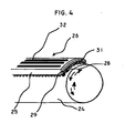
- FIG. 4 is a semi-schematic perspective view of an exemplary distal end of the hair styling tool of FIG. 1 .
- FIG. 5 is a side view of an exemplary hair styling tool of the present invention with a styling arm in the closed position.
- FIG. 6 is a semi-schematic, partial cross-section, side elevation view of another exemplary hair styling tool of the present invention.
- FIG. 7 is a side elevation view of yet another exemplary hair styling tool of the present invention.
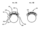
- FIG. 8A is a partially schematic front view of the distal end of an exemplary hair styling tool of the present invention with compressible bristles in an extended position.
- FIG. 8B is a semi-schematic front view of the distal end of FIG. 8A with the bristles in a collapsed position.
- FIG. 8C is a side view of a styling arm and a cylinder of a hair styling tool of the present invention.
- FIG. 8D is a semi-schematic front view of a distal end of a hair styling tool having a smoothing plate without bristles.
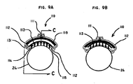
- FIG. 9A is a semi-schematic front view of a distal end of a hair styling tool of the present invention with retractable bristles in the extended position.
- FIG. 9B is a semi-schematic front view of the distal end of FIG. 9A with retractable bristles in the collapsed position.
- FIG. 9C is a side view of a brush head and a cylinder of a hair styling tool of the present invention.
- FIG. 10 is a partial cross-section, side elevation view of yet another exemplary hair styling tool of the present invention.
- FIG. 11 is a semi-schematic side view of yet another exemplary embodiment of a hair styling tool of the present invention.
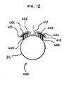
- FIG. 12 is a front view of a distal end of an exemplary hair brush of the present invention having a fixed bristles brush head incorporating an integral smoothing plate.
- a hair styling tool 20 includes an elongated body 22 .
- the specific dimensions of the body are not critical, but the body should generally allow a user to comfortably hold the hair styling tool during use.
- the body 22 may be adapted to house other mechanical and electrical components of the hair styling tool 20 , as described in more detail below.
- a mounting channel 72 extends from a distal end of the body 22.
- distal shall generally refer to a position or direction away from a base of the body 22 or towards a tip of the mounting channel 72 .
- proximal shall generally refer to a position or direction toward the base of the body 22 or away from the tip of the hot air channel 72.
- the mounting channel 72 serves to provide additional support to a cylinder 24 rotatably mounted on the mounting channel.
- a hot air channel 71 may be connected to a hot air fan assembly 44 housed in the body 22 such that hot air provided by the hot air fan assembly travels through the body via the hot air channel.
- Intake ports 70 in the body 22 admit outside air to an inlet of the hot air fan assembly 44.
- An opening 82 at a distal end of the hot air channel 71 allows the air to escape the body 22 and enter, for example, a cylinder attached to a distal end of the body as described below.
- a hot air switch 42 electrically connected to the hot air fan assembly 44 allows a user to control the hot air supply provided by the hot air fan assembly.
- An elongated hollow cylinder 24 is rotatably mounted over the mounting channel 72.
- the mounting channel 72 may include a groove 81 into which teeth 83 protruding from a cap 27 of the cylinder 24 may be snapped to mount the cylinder to the mounting channel.
- a base 25 of the cylinder may be adapted to be connected to a distal portion of the body 22.
- the base 25 of the cylinder 24 is connected to the body 22 by a slip fit.
- teeth (not shown) on an inner circumference of the base 25 mesh with teeth on a cylinder drive gear 50 at a distal end of the body 22 to align the cylinder 24 to the body.
- a distal end of the cylinder 24 may include the cap 27 to seal the distal end of the cylinder and prevent, for example, hot air provided through the hot air channel 71 from escaping from the distal end of the cylinder.
- the cap 27 may contain teeth 83 to allow the cylinder to be mounted and secured by an interference fit to the mounting channel 72 as described above.
- the specific shape or dimensions of the cap 27 are not critical as long as the cap substantially covers the distal end of the cylinder 24 and prevents a significant amount of air from escaping from the distal end.
- the cylinder 24 includes a plurality of holes 30 which allow a flow of hot air from the hot air channel 72 to an exterior of the hair styling tool 20 and to contact hair adjacent the cylinder.
- the holes 30 are circular and arranged in rows, evenly spaced throughout the cylinder 24. The even spacing of the holes 30 throughout the cylinder 24 allows for even distribution of hot air throughout the cylinder and also for uniform heating of the cylinder, thus providing uniform drying when the cylinder is applied to hair, as described in more detail below.
- the holes 30 is described herein, the specific configuration of the holes is not critical, and the holes may be arranged in any configuration allowing hot air to travel from the hot air channel 72 through the cylinder 24.
- the described holes 30 are circular, the shape of the holes is not critical. The holes 30 also serve to increase the friction between the brush head housing and the cylinder, increasing the brushing effectiveness on the hair.
- alternate exemplary surface patterns of the cylinder 24 are shown.
- the alternate surface patterns which are generally wave-shaped grooves 54a, 54b, 54c, 54d, allow for varying friction along the cylinder's surface to provide different styling options when hair is placed between the cylinder 24 and a smoothing plate 108 as described in more detail below.
- the grooves may also be used on a cylinder 24 having holes 30 (holes not shown for clarity).
- the smoothing plate 108 adapted to contact the cylinder 24 may include grooves 55 to further increase the friction between the brush head housing and the cylinder.
- An electric motor 39 may be housed within the body 22, the motor being adapted to rotate the cylinder 24.
- the motor powers a drive shaft 46 which extends along a length of the body 22.
- a drive gear 48 may be located at a distal end of the drive shaft 46, the drive gear adapted to interact with the cylinder gear drive 50 such when the drive gear 48 is rotated by the drive shaft, the cylinder gear drive 50 rotates as well.
- the electric motor 39 is adapted to power the drive shaft 46 at different rates, depending on a setting adjusted by a user.
- the electric motor 39 is reversible such that it can rotate the drive shaft 48 in either direction.
- a rotation direction switch 41 may be electrically connected to the motor 39 to allow the direction of the motor to be set by a user.
- the motor 39 may be powered by, for example, electricity from an electrical power cord 40, a rechargeable battery, or by other means sufficient to generate enough energy to power the motor.
- An activation switch 38 may be used to activate the motor 39 to drive rotation of the cylinder 24.
- the activation switch 38 may be located anywhere on the brush, but in exemplary embodiment, the rotation switch is located in a position such that it is activated when a pivot handle 36 is in a closed position, as described in more detail below.
- An elongated styling arm is attached to the body 22 of the hair styling tool 20 , the styling arm is a brush head 26.
- the brush head 26 includes an array of bristles 28 mounted on a surface of the brush head and protruding toward an outer surface of the cylinder 24.
- the brush head 26 may also include vent holes 32 to allow hot air to enter or hot air and/or steam to escape to prevent the brush head from becoming dangerously hot.
- An exemplary brush head 26 venting pattern is shown in FIG. 4 .
- the brush head 26 has a concave structure such that the brush head generally conforms to the curvature of the cylinder 24, maximizing the effective brushing surface.
- the brush head 26 may have a width such that it extends around part of the cylinder circumference to subtend an angle between about 20° and about 45°.
- the brush head 26 may be adapted to receive and secure an interchangeable bristle blade 31, allowing users to choose from a variety of blades having, for example, different widths, different bristle densities and different bristle textures.
- the brush head 26 may include a groove 29 located along each interior side of the brush head, the grooves 29 adapted to slidingly receive and secure the interchangeable bristle blade 31.
- the brush head 26 may be pivotally or otherwise movably attached to the body 22. More specifically, the brush head 26 may be attached to a distal end of a lever arm 34, the lever arm being pivotally attached to the body 22 by, for example, a transverse brush head pivot pin 35.
- the brush head 26 may have an open position wherein the brush head 26 is spaced from the cylinder 24, and a closed position ( FIG. 5 ) wherein the brush head 26, and specifically, the bristles 28, are in contact with the cylinder.
- a bias means 84 such as a spring, may bias the brush head 26 into an open position.
- the pivot handle 36 may be provided to allow a user to move the brush head 26 from the open position to the close position, the pivot handle being pivotally attached to the body 22 by a pivot handle pivot pin 37.
- a pivot handle gear 50 rotatably connected to the pivot handle pivot pin 37 is coupled with a brush head gear 52 rotatably coupled to the brush head pivot pin 35.
- the pivot handle 36 is oriented such that the pivot handle is in an open position (i.e., a proximal end of the pivot handle is spaced from the body 22) when the brush head 26 is in an open position and the pivot handle is in a closed position (i.e., a proximal end of the pivot handle is in contact or substantially in contact with the body) ( FIG.
- a hair styling tool 120 includes a heating element such as a heating rod 60 which is adapted to provide heat to a cylinder 124 rotatably attached to a mounting channel similarly to the previous embodiment.
- the heating rod 60 may be electrically connected to a power source, such as the power cord 40, which provides the heating rod 60 with the ability to generate heat.
- a heating element switch 62 located on a body 122 allows a user to activate and deactivate the heating rod 60.
- the cylinder 124 includes a heat transfer assembly 64 attached to an inner circumferential surface of the cylinder and adapted to allow the cylinder to slide over and make contact with the heating rod 60.
- the heat transfer assembly 64 may be any suitable heat transfer material, for example, plastic, metal, ceramic, or any combination thereof. Accordingly, when the heating rod 60 is heated, the heat is transferred by conduction from the heating rod to the heat transfer assembly 64 and to an exterior surface of the cylinder 124.
- the cylinder 124 includes holes 66, for example, concave indentations or convex protrusions, which enhance hair engagement as the cylinder rotates.
- an exterior surface of the cylinder 124 is slightly corrugated to increase the friction between the hair and the cylinder as the cylinder rotates.
- the styling arm includes a brush head 100 having a collapsible bristle assembly.
- the brush head 100 includes a brush head housing 104 adapted to slidingly receive the smoothing plate 108 into grooves 121 extending longitudinally along both sides of the brush head housing.
- the smoothing plate is heatable and in one exemplary embodiment the brush head housing may include an integrated plug electrically connected to the smoothing plate 108. When power is supplied to the plug, the plug heats the smoothing plate 108 allowing the smoothing plate to act similar to a curling iron or a straightening iron, as described in more detail below.
- the brush head housing 104 is also adapted to slidingly receive a blade 105 including bristle clusters 106 and rigid posts 107.
- the blade 105 includes a plurality of collapsible members 123 extending longitudinally along the blade and having a generally concave cross-section.
- the collapsible members 123 have an extended position in which they provide for the bristles 106 to protrude from the smoothing plate 108 ( FIG. 8A ) and a collapsed position in which they provide for the bristles to be retracted with respect to the smoothing plate, i.e., recessed within or substantially flush with the smoothing plate ( FIG. 8B ).
- the collapsible members 123 are biased into the extended position, but may be transformed into the collapsed position by a force to overcome the bias. Specifically, when a sufficient compression force as indicated by the arrow in FIG. 8A is applied to the rigid posts 107 generally perpendicular to a planar surface of the blade 105, the collapsible members 123 bend to allow the bristles 106 and posts 107 to be recessed within the brush head housing 104 and to allow the smoothing plate 108 to have a relatively smooth surface. As such, the hair brush may also serve as a straightening iron or a curling iron.
- a styling arm 200 includes a housing 223 adapted to slidingly receive a smoothing plate 208 into grooves 221 extending longitudinally along both sides of the housing.
- the smoothing plate 208 does not include bristles and is heatable, and in one exemplary embodiment, the housing 223 may include an integrated plug to electrically heat the smoothing plate. When power is supplied to the plug, the heater heats the smoothing plate 208 allowing the smoothing plate to be used to more effectively style hair.
- brush head 110 includes a brush head housing 112 adapted to slidingly receive a heatable smoothing plate 115 into grooves 131 extending longitudinally along both sides of the brush head housing.
- the brush head housing 112 may include an integrated plug 103 electrically connected to the smoothing plate 108.
- the brush head housing 112 is also adapted to slidingly receive a blade 113 including bristles 114.
- the brush head housing 112 includes a bristle release knob 111a/11b adapted to be received into a release knob slot 133 located on a planar surface of the brush head housing.
- a hull 116 of the release knob 111a contacts a spine 134 of the blade 113 to place the blade in an extended position such that the bristles 114 protrude through the smoothing plate 115.
- the spine 134 may extend along only a portion of the blade 113.
- the hair brush may also be used as a curling iron or a straightening iron.
- the brush head 400 is directed to a brush head which incorporates a brush and an integrated smoothing plate without changing a configuration of the brush head. More specifically, the brush head 400 includes a plurality of brush head housing sections 402, each housing section adapted to slidingly receive a blade 404 including bristles 408 into grooves 410 extending longitudinally along the housing section. In one exemplary embodiment, the brush head 400 includes two housing sections 404, but the specific number of housing sections is not critical.
- the brush head 400 may further include a smoothing plate section 412 disposed between adjacent housing sections 404, the smoothing plate section configured to provide a planar surface contact with the cylinder 24 when the brush head is in a closed configuration as shown in FIG. 12 .
- the smoothing plate section 412 has a concave surface curved to substantially the same degree as the cylinder such that the smoothing plate section makes substantially complete contact with the cylinder when the brush head is in the closed position.
- the brush head 400 may further include an integrated plug and heating element enabling the brush head to be electrically heated.
- a hair styling tool 320 substantially similar to the previously described hair styling tools is provided.
- the hair styling tool 320 includes a one-piece movable brush head assembly 330.
- the brush head assembly 330 includes a brush head 326 attached to a distal end of a lever arm 390.
- the lever arm 390 is generally in the shape of an "S" or an upside down “Z.”
- the lever arm 390 is rotatably connected to the hair styling tool 310 by a transverse pivot pin 391.
- a pivot preload spring 392 biases the lever arm 390 into an open position such that the brush head 326 is spaced from a cylinder 324.
- the lever arm 390 When a force to overcome the spring bias is applied to the lever arm 390, the lever arm is movable from the open position to a closed position wherein the brush head 326 contacts the cylinder 324.
- the body 322 of the hair styling tool 320 may include slots 323 which permit the lever arm 390 to be moved between the open position and the closed position.
- a cylinder rotation switch 338 may be located such that it is activated when the lever arm is in the closed position and deactivated when the lever arm is in the open position.
- a hair styling tool 149 has a hinged or "clam-shell" configuration including a body 152 and a styling arm 151 pivotally or otherwise movably attached to the body.
- the styling arm 151 may be attached by a pivot pin 153.
- the pivot pin 153 may be designed so as to allow only a limited degree of rotation between the styling arm 151 and the body 152. For example, the maximum amount of rotation may about 60 degrees.
- the body 152 includes a rotatable cylinder 157 and the styling arm 151 includes a brush head 150.
- a heating element switch 155 to control heating of the cylinder 157 and the brush head 150, and a rotation switch 156 to control rotation of the cylinder are located on the styling arm 151.
- the location of such switches is not critical, and the switches may be located anywhere that is convenient for user access.
- the hair styling tool 149 may be electrically powered through a power cord 154.
- the styling arm 151 may be biased, for example, by a spring, into an open position such that the styling arm is not in contact with the cylinder 24. A force to overcome the bias may be applied to the styling arm 151 to place the styling arm in a closed position wherein the styling arm contacts the cylinder.
- the hair styling tool may be used by placing a selected portion of hair between the brush head 26 and the cylinder 24 when the brush head is in the open position ( FIG. 1 ).
- the pivot handle 36 may then be moved from the open position to the closed position, resulting in the simultaneous movement of the brush head 26 from its open position to its closed position. Placing the brush head 26 in the closed position allows the brush head to clamp the selection portion of hair between the cylinder 24 and the bristles 28 of the brush head.
- placing the pivot handle 36 in the closed position triggers the rotation switch 38 to activate rotation of the cylinder 24.
- hair styling tools described may be used in a similar manner. Namely, hair may be placed between the styling arm and the cylinder when the styling arm is in the open position. Once the hair is in place, the styling arm may be moved to the closed position to capture and style the hair.
- the rotation direction of the cylinder is reversible, a user can use the brush with either hand or from either side of the head while having the cylinder rotate in the same general direction with respect to the hair.
- the brushing, shaping and styling effects may be enhanced by using the heat apparatus associated with exemplary embodiments of the brush.
- the hot air fan assembly 44 or the heating rod may be activated to heat the cylinder 24 as it rotates.
- the heatable smoothing plates 108, 115, 208 or 412 of the brush heads 100, 110, 200 or 400 may be heated. The heat applied to the hair by the cylinder 24 and/or the brush heads 100, 110, 200 or 400 not only allows the hair to dry more quickly, but also provides the hair with smoothing volume and a healthy shine.
- a compression force generally perpendicularly to the smoothing plate 108 may be applied to the blade 105 to place the bristles 106 in the collapsed position.
- the bristles 106 of the brush head are retracted with respect to the smoothing plate 108, i.e. recessed within or flush with the smoothing plate.
- the smoothing plate will have a smooth surface which, along with heat provided through the cylinder 24 and/or through the brush head, allows the device to be used as a smoothing, straightening or curling iron.
- the user slides the release knob 111 distally along the slot 133 from position 111a to position 111b such that the spine 134 of the blade 113 does not make contact with the hull 116 of the release knob 111. Then, the user can apply a compression force to the blade 113 to cause ends of the bristles 114 to be retracted with respect to the smoothing plate.
- the combination of bristle clusters 408 fixed in relationship to the heated flat iron section 412 allows the user to simultaneously brush and smooth, straighten or curl hair without having to change a configuration of the brush head 400.
Landscapes
- Brushes (AREA)
- Hair Curling (AREA)
Claims (18)
- Werkzeug zum Stylen und Kämmen von Haaren, wobei das Werkzeug folgendes umfasst:einen Körper (22);einen Zylinder (24), der sich von dem Körper (22) erstreckt, wobei der Zylinder (24; 124) im Verhältnis zu dem Körper (22) drehbar ist;einen Motor (39), der den Zylinder (24) drehen kann;eine Heizeinrichtung zum Erhitzen des Zylinders (24);gekennzeichnet durch:einen Stylingarm, der drehbar an dem Körper (22) vorgesehen und zwischen einer offenen Stellung und einer geschlossenen Stellung beweglich ist, wobei der Stylingarm folgendes umfasst:eine Glättungsplatte (108; 208; 115; 412), die allgemein zu dem Zylinder (24) ausgerichtet ist; und eine Mehrzahl von Borsten (28; 106; 114; 408), die über die Glättungsplatte (108; 208; 115; 412) und allgemein in Richtung des Zylinders (24) von dem Stylingarm angrenzend an die Glättungsplatte (108; 208; 115; 412) vorstehen.
- Werkzeug nach Anspruch 1, wobei der Zylinder ununterbrochen im Verhältnis zu dem Körper drehbar ist.
- Werkzeug nach Anspruch 1 oder 2, wobei der Stylingarm ferner ein Heizelement (6t0) zum Erhitzen des Stylingarms umfasst.
- Werkzeug nach einem der Ansprüche 1 bis 3, wobei die Glättungsplatte (108; 208; 115; 412) nicht drehbar ist.
- Werkzeug nach einem der Ansprüche 1 bis 4, wobei der Stylingarm eine konkave Oberfläche aufweist, die im Wesentlichen im gleichen Ausmaß gekrümmt ist wie der Zylinder (24).
- Werkzeug nach einem der Ansprüche 1 bis 5, wobei der Stylingarm an die offene Stellung vorbelastet ist.
- Werkzeug nach einem der Ansprüche 1 bis 6, wobei es sich bei der Heizeinrichtung um eine Einrichtung handelt, die aus einem Heizelement (60) und einem Heißluftgebläse (44) ausgewählt wird.
- Werkzeug nach einem der Ansprüche 1 bis 7, wobei die Mehrzahl von Borsten (28; 106; 114; 408) flexibel sind.
- Werkzeug nach einem der Ansprüche 1 bis 8, wobei es sich bei dem Zylinder (24) um einen texturierten Zylinder handelt.
- Werkzeug nach Anspruch 9, wobei der texturierte Zylinder (24) eine Textur aufweist, die aus Rillen und Löchern ausgewählt wird.
- Werkzeug nach einem der Ansprüche 1 bis 10, wobei dieses ferner einen Schalter (38) umfasst, der den Motor (39) aktiviert, so dass der Zylinder (24) gedreht wird, wenn der Stylingarm aus der offenen Stellung an die geschlossene Stellung bewegt wird.
- Werkzeug nach einem der Ansprüche 1 bis 11, wobei die Mehrzahl von Borsten (28; 106; 114, 408) ein Paar von Borstengruppen definieren, wobei sich jede Borstengruppe von dem Stylingarm entlang einer der Seiten der Glättungsplatte erstreckt.
- Werkzeug nach einem der Ansprüche 1 bis 12, wobei die Mehrzahl von Borsten (28; 106; 114; 408) im Verhältnis zu der Glättungsplatte (108; 208; 115; 412) einziehbar sind.
- Werkzeug nach einem der Ansprüche 1 bis 13, wobei der Körper (22) eine Längsachse sowie ein proximales Ende und ein distales Ende aufweist, wobei sich der Zylinder (24) von dem distalen Ende des Körpers (22) erstreckt und eine Längsachse aufweist, die mit der Längsachse des elongierten körpers ausgerichtet ist, und wobei der Stylingarm in der Nähe des proximalen Endes des elongierten Körpers drehbar mit dem Körper (22) verbunden ist, wobei der Stylingarm eine Längsachse aufweist, die sowohl an der offenen Stellung als auch an der geschlossenen Stellung transversal zu der Längsachse des Körpers ist.
- Verfahren zum Stylen der Haare einer Person unter Verwendung eines Werkzeugs nach einem der vorstehenden Ansprüche, wobei das Verfahren die folgenden Schritte umfasst:(a) das Platzieren der Haare zwischen dem Zylinder (24) und dem Stylingarm (26, 34, 200), wobei sich der Stylingarm (26, 34, 200) an dessen offenen Stellung befindet;(b) das Bewegen des Stylingarms (26, 34, 200) an dessen geschlossene Stellung sowie das Aktivieren der Rotation des Zylinders (24); und(c) das Stylen, Kämmen oder Formen der Haare.
- Verfahren nach Anspruch 15, wobei der Schritt (c) das Glätten der Haare umfasst.
- Werkzeug nach einem der Ansprüche 1 bis 14, wobei der Zylinder (24) in ausreichender Weise zum Glätten der Haare drehbar ist.
- Werkzeug nach einem der Ansprüche 1 bis 14, wobei der Zylinder (24) im Verhältnis zu dem Körper (22) vollständig drehbar ist.
Priority Applications (1)
| Application Number | Priority Date | Filing Date | Title |
|---|---|---|---|
| EP10163196.8A EP2229837B1 (de) | 2006-02-24 | 2007-02-26 | Haarstylingwerkzeug mit drehbarem Zylinder |
Applications Claiming Priority (3)
| Application Number | Priority Date | Filing Date | Title |
|---|---|---|---|
| US77647606P | 2006-02-24 | 2006-02-24 | |
| US11/678,559 US7481228B2 (en) | 2006-02-24 | 2007-02-23 | Hair styling tool with rotatable cylinder |
| PCT/US2007/005128 WO2007100842A2 (en) | 2006-02-24 | 2007-02-26 | Hair styling tool with rotatable cylinder |
Related Child Applications (2)
| Application Number | Title | Priority Date | Filing Date |
|---|---|---|---|
| EP10163196.8A Division EP2229837B1 (de) | 2006-02-24 | 2007-02-26 | Haarstylingwerkzeug mit drehbarem Zylinder |
| EP10163196.8 Division-Into | 2010-05-19 |
Publications (3)
| Publication Number | Publication Date |
|---|---|
| EP1991083A2 EP1991083A2 (de) | 2008-11-19 |
| EP1991083A4 EP1991083A4 (de) | 2009-04-01 |
| EP1991083B1 true EP1991083B1 (de) | 2013-08-21 |
Family
ID=38442851
Family Applications (2)
| Application Number | Title | Priority Date | Filing Date |
|---|---|---|---|
| EP10163196.8A Active EP2229837B1 (de) | 2006-02-24 | 2007-02-26 | Haarstylingwerkzeug mit drehbarem Zylinder |
| EP07751860.3A Active EP1991083B1 (de) | 2006-02-24 | 2007-02-26 | Haarstylingwerkzeug mit drehbarem zylinder |
Family Applications Before (1)
| Application Number | Title | Priority Date | Filing Date |
|---|---|---|---|
| EP10163196.8A Active EP2229837B1 (de) | 2006-02-24 | 2007-02-26 | Haarstylingwerkzeug mit drehbarem Zylinder |
Country Status (14)
| Country | Link |
|---|---|
| US (1) | US7481228B2 (de) |
| EP (2) | EP2229837B1 (de) |
| JP (1) | JP4741682B2 (de) |
| KR (1) | KR101065441B1 (de) |
| CN (1) | CN101426393B (de) |
| BR (1) | BRMU8702850Y1 (de) |
| CA (1) | CA2638149C (de) |
| GB (1) | GB2452170B (de) |
| HK (2) | HK1128209A1 (de) |
| IL (1) | IL193647A (de) |
| MX (1) | MX2008010855A (de) |
| RU (2) | RU2433770C2 (de) |
| WO (1) | WO2007100842A2 (de) |
| ZA (1) | ZA200808186B (de) |
Cited By (1)
| Publication number | Priority date | Publication date | Assignee | Title |
|---|---|---|---|---|
| WO2019014150A1 (en) * | 2017-07-09 | 2019-01-17 | Masood Habibi | AUTOMATIC SHAPING MECHANISM |
Families Citing this family (40)
| Publication number | Priority date | Publication date | Assignee | Title |
|---|---|---|---|---|
| DE102005000782A1 (de) | 2005-01-05 | 2006-07-20 | Voith Paper Patent Gmbh | Trockenzylinder |
| DE102005000794A1 (de) * | 2005-01-05 | 2006-07-13 | Voith Paper Patent Gmbh | Vorrichtung und Verfahren zur Herstellung und/oder Veredelung einer Faserstoffbahn |
| DE102005000795A1 (de) * | 2005-01-05 | 2006-07-13 | Voith Paper Patent Gmbh | Vorrichtung und Verfahren zur Herstellung und/oder Veredelung einer Faserstoffbahn |
| WO2006133077A2 (en) * | 2005-06-03 | 2006-12-14 | Conair Corporation | Hair brush with curved styling surfaces |
| US7631646B2 (en) | 2006-02-24 | 2009-12-15 | Mm&R Products, Inc. | Hair styling tool with rotatable cylinder |
| US7987859B2 (en) * | 2007-03-07 | 2011-08-02 | Helen Of Troy Limited | Adjustable multi-barrel hair waving appliance |
| FR2916944B1 (fr) * | 2007-06-11 | 2009-08-14 | Seb Sa | Appareil de coiffure |
| KR101014054B1 (ko) * | 2009-05-08 | 2011-02-14 | 김계수 | 회전형 헤어 아이론 |
| WO2011060569A1 (en) * | 2009-11-17 | 2011-05-26 | Sun Luen Electrical Manufacturing Company Limited | A hair styling apparatus and method |
| KR101196487B1 (ko) * | 2009-12-24 | 2012-11-01 | 최명표 | 브러시 아이언기 |
| CN201822159U (zh) * | 2010-04-09 | 2011-05-11 | 建福实业有限公司 | 电动定型烫发器 |
| FR2960747A1 (fr) | 2010-06-07 | 2011-12-09 | Seb Sa | Appareil de coiffure avec mandrin motorise |
| KR200452210Y1 (ko) * | 2010-07-29 | 2011-02-14 | 김계수 | 회전형 헤어 아이론 |
| KR101025747B1 (ko) * | 2010-08-06 | 2011-04-04 | 오창민 | 회전식 헤어 고데기 |
| GB201021458D0 (en) | 2010-12-17 | 2011-02-02 | Tf3 Ltd | Hair styling device |
| US8573231B2 (en) | 2011-01-12 | 2013-11-05 | M. M. & R. Products, Inc. | Hair styling tool with movable dividers |
| US9398796B2 (en) | 2011-03-22 | 2016-07-26 | The Beachwaver Co. | Hair styling device |
| EP2630950A1 (de) * | 2012-02-21 | 2013-08-28 | Kao Germany GmbH | Haarbehandlungsverfahren |
| FR2988272B1 (fr) | 2012-03-22 | 2014-06-27 | Seb Sa | Appareil de coiffure |
| CN102747892B (zh) * | 2012-07-06 | 2014-10-22 | 上海奔腾电工有限公司 | 一种直发器的闭夹锁改良结构 |
| US8881423B2 (en) | 2012-08-24 | 2014-11-11 | M. M. & R. Products, Inc. | Concentrator |
| US20140076349A1 (en) * | 2012-09-17 | 2014-03-20 | Shenzhen Fashion Beauty Technology Co., Ltd. | Hair Curling Device |
| KR101291762B1 (ko) * | 2013-04-26 | 2013-07-31 | 유희상 | 퍼머 및 고데 겸용 기기 |
| HU230410B1 (hu) | 2013-05-08 | 2016-04-28 | Olivér Palotai | Hajformázó készülék, hajban és szőrzetben való minta elhelyezésére, és eljárás annak alkalmazására |
| DE102013107778B4 (de) * | 2013-07-22 | 2019-12-19 | Wik Far East Ltd. | Verfahren zum Formen von Locken oder Wellen von Haar mit einem Haarformgerät sowie Haarformgerät |
| EP3046440A4 (de) | 2013-09-17 | 2017-06-07 | Trade Box, Llc | Haarstylingvorrichtung mit greifspitze |
| US9474347B2 (en) * | 2014-02-11 | 2016-10-25 | Christopher Lee Pedroarena | Cordless hairstyling tools with rechargeable and interchangeable batteries |
| FR3023139B1 (fr) * | 2014-07-02 | 2018-02-16 | Seb Sa | Appareil de coiffure pour former des boucles de tailles differentes |
| GB2542207B (en) * | 2015-09-14 | 2021-06-16 | Jemella Ltd | Apparatus and method for drying hair |
| US10058158B2 (en) | 2015-11-06 | 2018-08-28 | Conair Corporation | Hair waving apparatus |
| USD773119S1 (en) | 2015-11-06 | 2016-11-29 | Conair Corporation | Hair waving apparatus |
| AU2016100897A4 (en) * | 2016-01-21 | 2016-07-21 | Trade Box, Llc | Heated hair curling device with retainer arm |
| USD799134S1 (en) | 2016-01-27 | 2017-10-03 | Carissa Davino | Extendable flatiron |
| GB2553510B (en) * | 2016-08-30 | 2020-03-25 | Dyson Technology Ltd | A handheld appliance |
| FR3056084B1 (fr) * | 2016-09-21 | 2020-12-11 | Seb Sa | Appareil de coiffure equipe d'un element de guidage |
| FR3060266B1 (fr) * | 2016-12-21 | 2018-12-07 | Seb S.A. | Appareil de coiffure equipe d'un dispositif de guidage elastique d'une meche |
| FR3070839A1 (fr) * | 2017-09-12 | 2019-03-15 | L'oreal | Applicateur cosmetique |
| US11116307B2 (en) * | 2017-12-15 | 2021-09-14 | Rose Coppee | Modular hair brush dispensing styling products |
| USD959053S1 (en) | 2018-03-09 | 2022-07-26 | M. M. & R. Products, Inc. | Hair styling apparatus |
| USD900391S1 (en) * | 2018-03-09 | 2020-10-27 | M.M. & R. Products, Inc. | Hair styling apparatus |
Citations (2)
| Publication number | Priority date | Publication date | Assignee | Title |
|---|---|---|---|---|
| US4591695A (en) * | 1984-05-18 | 1986-05-27 | Taro Inoue | Rotatable barrel curling iron |
| JPH06209815A (ja) * | 1993-01-14 | 1994-08-02 | Matsushita Electric Works Ltd | ヘアカール器 |
Family Cites Families (43)
| Publication number | Priority date | Publication date | Assignee | Title |
|---|---|---|---|---|
| US524654A (en) | 1894-08-14 | Half to william t | ||
| US54695A (en) | 1866-05-15 | Improvement in folding hair-brushes | ||
| US431497A (en) | 1890-07-01 | Grooming device | ||
| US1572161A (en) * | 1925-03-30 | 1926-02-09 | Thomas C Russell | Hair-straightening iron |
| DE1062212B (de) | 1958-01-13 | 1959-07-30 | Dr Ludwig Yberle | Zahnbuerste mit umlaufendem Buerstenteil |
| US3019463A (en) | 1959-09-02 | 1962-02-06 | Samuel L Mitchell | Power hair brush |
| US3431571A (en) | 1966-10-26 | 1969-03-11 | Donald Edward Kraus | Rotary driven hairbrush |
| US3947910A (en) | 1972-12-29 | 1976-04-06 | Jean Akerman | Automatic hair brush |
| GB1427452A (en) | 1973-02-26 | 1976-03-10 | Nogues P | Cylindrical hairbrush |
| US3890984A (en) | 1974-01-23 | 1975-06-24 | Alexander C Lesetar | Hair dryer with rotary brush |
| FR2276794A1 (fr) | 1974-07-01 | 1976-01-30 | Lardenois Ets | Ustensile de coiffure du type bigoudi ou brosse |
| JPS51125566A (en) | 1974-08-16 | 1976-11-02 | Matsushita Electric Works Ltd | Hair dresser |
| US4023578A (en) | 1974-11-08 | 1977-05-17 | Etablissements Lardenois | Blow-wave brush |
| US4034201A (en) | 1975-04-28 | 1977-07-05 | Clairol Incorporated | Steam curling iron having interchangeable hair winding mandrels |
| CH594382A5 (en) | 1975-09-08 | 1978-01-13 | Solis Ag Apparatefabriken | Hair dressing brush with handle and wire cage |
| DE2649565A1 (de) | 1976-10-29 | 1978-05-03 | Otto Huebner | Rundbuerste |
| US4084282A (en) | 1977-06-27 | 1978-04-18 | Calvert Madeleine M | Rotary brush for removing hair from hair brushes |
| US4161050A (en) | 1977-07-01 | 1979-07-17 | Kao Soap Co., Ltd. | Hair brush |
| FR2397170A1 (fr) * | 1977-07-12 | 1979-02-09 | Nicolo Volpe Salvatore De | Appareil chauffant pour l'execution d'ondulations de la chevelure |
| US4197608A (en) | 1978-08-30 | 1980-04-15 | S. E. Jones | Rolling hairbrush |
| US4442849A (en) * | 1980-12-09 | 1984-04-17 | Idea Giken Ltd. | Curling iron |
| FR2577774B1 (fr) | 1985-02-27 | 1989-08-25 | Celluloid Sa | Brosse a cheveux |
| JPH0616724B2 (ja) | 1986-06-16 | 1994-03-09 | 有本 利道 | コンピュータ支援によるアイロン理容美容法 |
| JPS63125901A (ja) * | 1986-11-14 | 1988-05-30 | Matsushita Electric Ind Co Ltd | 赤外用反射防止膜 |
| JPH0418481Y2 (de) | 1987-02-09 | 1992-04-24 | ||
| IT1220123B (it) | 1987-11-02 | 1990-06-06 | Dyanex Di Bandelli D & Visinti | Spazzola rotante per levigatura |
| SU1676584A1 (ru) * | 1989-05-31 | 1991-09-15 | А.Н.Бобков | Электробигуди |
| FR2705875B1 (fr) * | 1993-06-04 | 1995-07-13 | Seb Sa | Appareil de traitement et/ou de mise en forme des cheveux comportant un tube de distribution de vapeur. |
| US5584088A (en) | 1995-11-06 | 1996-12-17 | Pauldine; Concetta J. | Rotating hair brush |
| US6098635A (en) | 1997-12-18 | 2000-08-08 | Marino; Claudio | Motorized, rotating hair brush |
| US6070594A (en) | 1998-02-25 | 2000-06-06 | Arich, Inc. | Brush with retractable bristles |
| US6070596A (en) | 1998-09-25 | 2000-06-06 | Wahl Clipper Corporation | Heated hair styling device |
| US6158073A (en) | 1999-02-01 | 2000-12-12 | Jiovanni; Matthew | Round brush apparatus for brushing a person's hair |
| USD439051S1 (en) | 2000-04-24 | 2001-03-20 | Patrick S. White | Rotary electric hair brush motor unit |
| WO2002058503A1 (de) * | 2001-01-26 | 2002-08-01 | IFLAND, Jürgen | Vorrichtung zum wellen und glätten von haaren |
| KR200253685Y1 (ko) * | 2001-05-15 | 2001-11-23 | 한정용 | 회전식 머리 손질기 |
| USD466693S1 (en) | 2002-01-18 | 2002-12-10 | Revolutionary Products, Inc. | Rotatable hairbrush |
| USD465654S1 (en) | 2002-01-18 | 2002-11-19 | Revolutionary Products, Inc. | Combined rotatable hairbrush and support base |
| KR200320666Y1 (ko) | 2003-04-30 | 2003-07-25 | 오용호 | 미용용 고데기 |
| JP2005080850A (ja) * | 2003-09-08 | 2005-03-31 | Naomoto Kogyo Kk | ヘアーアイロン装置 |
| KR200385754Y1 (ko) * | 2005-03-08 | 2005-06-02 | 유닉스전자주식회사 | 전동식 헤어스타일링 아이론 |
| WO2006097824A1 (en) * | 2005-03-14 | 2006-09-21 | Elysee Beauty Products, Ltd | Revolvable hair curling iron |
| US20060278251A1 (en) * | 2005-06-09 | 2006-12-14 | Hur Suhp | Hair curling iron |
-
2007
- 2007-02-23 US US11/678,559 patent/US7481228B2/en active Active
- 2007-02-26 WO PCT/US2007/005128 patent/WO2007100842A2/en active Search and Examination
- 2007-02-26 CN CN2007800144650A patent/CN101426393B/zh active Active
- 2007-02-26 CA CA2638149A patent/CA2638149C/en active Active
- 2007-02-26 ZA ZA200808186A patent/ZA200808186B/xx unknown
- 2007-02-26 BR BRMU8702850U patent/BRMU8702850Y1/pt active IP Right Grant
- 2007-02-26 EP EP10163196.8A patent/EP2229837B1/de active Active
- 2007-02-26 EP EP07751860.3A patent/EP1991083B1/de active Active
- 2007-02-26 RU RU2008137969/05A patent/RU2433770C2/ru not_active Application Discontinuation
- 2007-02-26 KR KR1020087023231A patent/KR101065441B1/ko active IP Right Review Request
- 2007-02-26 GB GB0817398A patent/GB2452170B/en active Active
- 2007-02-26 RU RU2011127049/12A patent/RU2478325C2/ru active IP Right Revival
- 2007-02-26 MX MX2008010855A patent/MX2008010855A/es active IP Right Grant
- 2007-02-26 JP JP2008556482A patent/JP4741682B2/ja active Active
-
2008
- 2008-08-24 IL IL193647A patent/IL193647A/en active IP Right Grant
-
2009
- 2009-06-26 HK HK09105750.0A patent/HK1128209A1/xx unknown
-
2011
- 2011-03-17 HK HK11102680.8A patent/HK1148654A1/zh unknown
Patent Citations (2)
| Publication number | Priority date | Publication date | Assignee | Title |
|---|---|---|---|---|
| US4591695A (en) * | 1984-05-18 | 1986-05-27 | Taro Inoue | Rotatable barrel curling iron |
| JPH06209815A (ja) * | 1993-01-14 | 1994-08-02 | Matsushita Electric Works Ltd | ヘアカール器 |
Cited By (1)
| Publication number | Priority date | Publication date | Assignee | Title |
|---|---|---|---|---|
| WO2019014150A1 (en) * | 2017-07-09 | 2019-01-17 | Masood Habibi | AUTOMATIC SHAPING MECHANISM |
Also Published As
| Publication number | Publication date |
|---|---|
| HK1148654A1 (zh) | 2011-09-16 |
| EP1991083A2 (de) | 2008-11-19 |
| JP4741682B2 (ja) | 2011-08-03 |
| WO2007100842A8 (en) | 2008-03-13 |
| HK1128209A1 (en) | 2009-10-23 |
| IL193647A (en) | 2011-09-27 |
| RU2433770C2 (ru) | 2011-11-20 |
| GB2452170B (en) | 2011-01-19 |
| GB0817398D0 (en) | 2008-10-29 |
| ZA200808186B (en) | 2010-01-27 |
| US20070199574A1 (en) | 2007-08-30 |
| RU2011127049A (ru) | 2013-01-10 |
| EP2229837A1 (de) | 2010-09-22 |
| KR20080097234A (ko) | 2008-11-04 |
| KR101065441B1 (ko) | 2011-09-19 |
| CN101426393B (zh) | 2012-07-18 |
| WO2007100842A2 (en) | 2007-09-07 |
| EP2229837B1 (de) | 2016-02-17 |
| CA2638149C (en) | 2012-07-10 |
| US7481228B2 (en) | 2009-01-27 |
| EP1991083A4 (de) | 2009-04-01 |
| IL193647A0 (en) | 2009-08-03 |
| GB2452170A (en) | 2009-02-25 |
| CN101426393A (zh) | 2009-05-06 |
| MX2008010855A (es) | 2008-11-14 |
| JP2009527338A (ja) | 2009-07-30 |
| RU2478325C2 (ru) | 2013-04-10 |
| BRMU8702850U2 (pt) | 2011-02-22 |
| WO2007100842A3 (en) | 2007-11-29 |
| BRMU8702850Y1 (pt) | 2016-11-29 |
| RU2008137969A (ru) | 2010-03-27 |
| CA2638149A1 (en) | 2007-09-07 |
Similar Documents
| Publication | Publication Date | Title |
|---|---|---|
| EP1991083B1 (de) | Haarstylingwerkzeug mit drehbarem zylinder | |
| US9521891B2 (en) | Hair styling tool with rotatable cylinder | |
| US20130319450A1 (en) | Hairstyling Tool With Automatically Reversing Cylinder | |
| US6119702A (en) | Heated hair styling system | |
| EA012354B1 (ru) | Устройство для укладки волос | |
| WO2011021783A2 (ko) | 전기 고데기 | |
| KR102321237B1 (ko) | 다용도 헤어 스타일러 | |
| TWI383759B (zh) | 具有可旋轉式圓柱之頭髮造型器 | |
| KR20210000744U (ko) | 클램프를 구비하는 빗살형 고데기 |
Legal Events
| Date | Code | Title | Description |
|---|---|---|---|
| PUAI | Public reference made under article 153(3) epc to a published international application that has entered the european phase |
Free format text: ORIGINAL CODE: 0009012 |
|
| 17P | Request for examination filed |
Effective date: 20080923 |
|
| AK | Designated contracting states |
Kind code of ref document: A2 Designated state(s): AT BE BG CH CY CZ DE DK EE ES FI FR GB GR HU IE IS IT LI LT LU LV MC NL PL PT RO SE SI SK TR |
|
| A4 | Supplementary search report drawn up and despatched |
Effective date: 20090302 |
|
| 17Q | First examination report despatched |
Effective date: 20090827 |
|
| TPAC | Observations filed by third parties |
Free format text: ORIGINAL CODE: EPIDOSNTIPA |
|
| DAX | Request for extension of the european patent (deleted) | ||
| GRAP | Despatch of communication of intention to grant a patent |
Free format text: ORIGINAL CODE: EPIDOSNIGR1 |
|
| GRAS | Grant fee paid |
Free format text: ORIGINAL CODE: EPIDOSNIGR3 |
|
| GRAA | (expected) grant |
Free format text: ORIGINAL CODE: 0009210 |
|
| AK | Designated contracting states |
Kind code of ref document: B1 Designated state(s): AT BE BG CH CY CZ DE DK EE ES FI FR GB GR HU IE IS IT LI LT LU LV MC NL PL PT RO SE SI SK TR |
|
| REG | Reference to a national code |
Ref country code: GB Ref legal event code: FG4D |
|
| REG | Reference to a national code |
Ref country code: CH Ref legal event code: EP |
|
| REG | Reference to a national code |
Ref country code: AT Ref legal event code: REF Ref document number: 627525 Country of ref document: AT Kind code of ref document: T Effective date: 20130915 |
|
| REG | Reference to a national code |
Ref country code: IE Ref legal event code: FG4D |
|
| REG | Reference to a national code |
Ref country code: DE Ref legal event code: R096 Ref document number: 602007032391 Country of ref document: DE Effective date: 20131017 |
|
| REG | Reference to a national code |
Ref country code: NL Ref legal event code: VDEP Effective date: 20130821 Ref country code: AT Ref legal event code: MK05 Ref document number: 627525 Country of ref document: AT Kind code of ref document: T Effective date: 20130821 |
|
| REG | Reference to a national code |
Ref country code: LT Ref legal event code: MG4D |
|
| PG25 | Lapsed in a contracting state [announced via postgrant information from national office to epo] |
Ref country code: PT Free format text: LAPSE BECAUSE OF FAILURE TO SUBMIT A TRANSLATION OF THE DESCRIPTION OR TO PAY THE FEE WITHIN THE PRESCRIBED TIME-LIMIT Effective date: 20131223 Ref country code: CY Free format text: LAPSE BECAUSE OF FAILURE TO SUBMIT A TRANSLATION OF THE DESCRIPTION OR TO PAY THE FEE WITHIN THE PRESCRIBED TIME-LIMIT Effective date: 20130619 Ref country code: IS Free format text: LAPSE BECAUSE OF FAILURE TO SUBMIT A TRANSLATION OF THE DESCRIPTION OR TO PAY THE FEE WITHIN THE PRESCRIBED TIME-LIMIT Effective date: 20131221 Ref country code: LT Free format text: LAPSE BECAUSE OF FAILURE TO SUBMIT A TRANSLATION OF THE DESCRIPTION OR TO PAY THE FEE WITHIN THE PRESCRIBED TIME-LIMIT Effective date: 20130821 Ref country code: AT Free format text: LAPSE BECAUSE OF FAILURE TO SUBMIT A TRANSLATION OF THE DESCRIPTION OR TO PAY THE FEE WITHIN THE PRESCRIBED TIME-LIMIT Effective date: 20130821 Ref country code: SE Free format text: LAPSE BECAUSE OF FAILURE TO SUBMIT A TRANSLATION OF THE DESCRIPTION OR TO PAY THE FEE WITHIN THE PRESCRIBED TIME-LIMIT Effective date: 20130821 |
|
| PG25 | Lapsed in a contracting state [announced via postgrant information from national office to epo] |
Ref country code: SI Free format text: LAPSE BECAUSE OF FAILURE TO SUBMIT A TRANSLATION OF THE DESCRIPTION OR TO PAY THE FEE WITHIN THE PRESCRIBED TIME-LIMIT Effective date: 20130821 Ref country code: FI Free format text: LAPSE BECAUSE OF FAILURE TO SUBMIT A TRANSLATION OF THE DESCRIPTION OR TO PAY THE FEE WITHIN THE PRESCRIBED TIME-LIMIT Effective date: 20130821 Ref country code: LV Free format text: LAPSE BECAUSE OF FAILURE TO SUBMIT A TRANSLATION OF THE DESCRIPTION OR TO PAY THE FEE WITHIN THE PRESCRIBED TIME-LIMIT Effective date: 20130821 Ref country code: BE Free format text: LAPSE BECAUSE OF FAILURE TO SUBMIT A TRANSLATION OF THE DESCRIPTION OR TO PAY THE FEE WITHIN THE PRESCRIBED TIME-LIMIT Effective date: 20130821 Ref country code: GR Free format text: LAPSE BECAUSE OF FAILURE TO SUBMIT A TRANSLATION OF THE DESCRIPTION OR TO PAY THE FEE WITHIN THE PRESCRIBED TIME-LIMIT Effective date: 20131122 Ref country code: PL Free format text: LAPSE BECAUSE OF FAILURE TO SUBMIT A TRANSLATION OF THE DESCRIPTION OR TO PAY THE FEE WITHIN THE PRESCRIBED TIME-LIMIT Effective date: 20130821 Ref country code: ES Free format text: LAPSE BECAUSE OF FAILURE TO SUBMIT A TRANSLATION OF THE DESCRIPTION OR TO PAY THE FEE WITHIN THE PRESCRIBED TIME-LIMIT Effective date: 20130821 |
|
| PG25 | Lapsed in a contracting state [announced via postgrant information from national office to epo] |
Ref country code: CY Free format text: LAPSE BECAUSE OF FAILURE TO SUBMIT A TRANSLATION OF THE DESCRIPTION OR TO PAY THE FEE WITHIN THE PRESCRIBED TIME-LIMIT Effective date: 20130821 |
|
| PG25 | Lapsed in a contracting state [announced via postgrant information from national office to epo] |
Ref country code: CZ Free format text: LAPSE BECAUSE OF FAILURE TO SUBMIT A TRANSLATION OF THE DESCRIPTION OR TO PAY THE FEE WITHIN THE PRESCRIBED TIME-LIMIT Effective date: 20130821 Ref country code: EE Free format text: LAPSE BECAUSE OF FAILURE TO SUBMIT A TRANSLATION OF THE DESCRIPTION OR TO PAY THE FEE WITHIN THE PRESCRIBED TIME-LIMIT Effective date: 20130821 Ref country code: DK Free format text: LAPSE BECAUSE OF FAILURE TO SUBMIT A TRANSLATION OF THE DESCRIPTION OR TO PAY THE FEE WITHIN THE PRESCRIBED TIME-LIMIT Effective date: 20130821 Ref country code: RO Free format text: LAPSE BECAUSE OF FAILURE TO SUBMIT A TRANSLATION OF THE DESCRIPTION OR TO PAY THE FEE WITHIN THE PRESCRIBED TIME-LIMIT Effective date: 20130821 Ref country code: SK Free format text: LAPSE BECAUSE OF FAILURE TO SUBMIT A TRANSLATION OF THE DESCRIPTION OR TO PAY THE FEE WITHIN THE PRESCRIBED TIME-LIMIT Effective date: 20130821 Ref country code: NL Free format text: LAPSE BECAUSE OF FAILURE TO SUBMIT A TRANSLATION OF THE DESCRIPTION OR TO PAY THE FEE WITHIN THE PRESCRIBED TIME-LIMIT Effective date: 20130821 |
|
| PG25 | Lapsed in a contracting state [announced via postgrant information from national office to epo] |
Ref country code: IT Free format text: LAPSE BECAUSE OF FAILURE TO SUBMIT A TRANSLATION OF THE DESCRIPTION OR TO PAY THE FEE WITHIN THE PRESCRIBED TIME-LIMIT Effective date: 20130821 |
|
| PLBE | No opposition filed within time limit |
Free format text: ORIGINAL CODE: 0009261 |
|
| STAA | Information on the status of an ep patent application or granted ep patent |
Free format text: STATUS: NO OPPOSITION FILED WITHIN TIME LIMIT |
|
| 26N | No opposition filed |
Effective date: 20140522 |
|
| REG | Reference to a national code |
Ref country code: DE Ref legal event code: R097 Ref document number: 602007032391 Country of ref document: DE Effective date: 20140522 |
|
| PG25 | Lapsed in a contracting state [announced via postgrant information from national office to epo] |
Ref country code: LU Free format text: LAPSE BECAUSE OF FAILURE TO SUBMIT A TRANSLATION OF THE DESCRIPTION OR TO PAY THE FEE WITHIN THE PRESCRIBED TIME-LIMIT Effective date: 20140226 Ref country code: MC Free format text: LAPSE BECAUSE OF FAILURE TO SUBMIT A TRANSLATION OF THE DESCRIPTION OR TO PAY THE FEE WITHIN THE PRESCRIBED TIME-LIMIT Effective date: 20130821 |
|
| REG | Reference to a national code |
Ref country code: CH Ref legal event code: PL |
|
| PG25 | Lapsed in a contracting state [announced via postgrant information from national office to epo] |
Ref country code: LI Free format text: LAPSE BECAUSE OF NON-PAYMENT OF DUE FEES Effective date: 20140228 Ref country code: CH Free format text: LAPSE BECAUSE OF NON-PAYMENT OF DUE FEES Effective date: 20140228 |
|
| REG | Reference to a national code |
Ref country code: IE Ref legal event code: MM4A |
|
| PG25 | Lapsed in a contracting state [announced via postgrant information from national office to epo] |
Ref country code: IE Free format text: LAPSE BECAUSE OF NON-PAYMENT OF DUE FEES Effective date: 20140226 |
|
| REG | Reference to a national code |
Ref country code: FR Ref legal event code: PLFP Year of fee payment: 10 |
|
| PG25 | Lapsed in a contracting state [announced via postgrant information from national office to epo] |
Ref country code: BG Free format text: LAPSE BECAUSE OF FAILURE TO SUBMIT A TRANSLATION OF THE DESCRIPTION OR TO PAY THE FEE WITHIN THE PRESCRIBED TIME-LIMIT Effective date: 20130821 |
|
| PG25 | Lapsed in a contracting state [announced via postgrant information from national office to epo] |
Ref country code: TR Free format text: LAPSE BECAUSE OF FAILURE TO SUBMIT A TRANSLATION OF THE DESCRIPTION OR TO PAY THE FEE WITHIN THE PRESCRIBED TIME-LIMIT Effective date: 20130821 Ref country code: HU Free format text: LAPSE BECAUSE OF FAILURE TO SUBMIT A TRANSLATION OF THE DESCRIPTION OR TO PAY THE FEE WITHIN THE PRESCRIBED TIME-LIMIT; INVALID AB INITIO Effective date: 20070226 |
|
| REG | Reference to a national code |
Ref country code: FR Ref legal event code: PLFP Year of fee payment: 11 |
|
| REG | Reference to a national code |
Ref country code: FR Ref legal event code: PLFP Year of fee payment: 12 |
|
| PGFP | Annual fee paid to national office [announced via postgrant information from national office to epo] |
Ref country code: FR Payment date: 20230110 Year of fee payment: 17 |
|
| PGFP | Annual fee paid to national office [announced via postgrant information from national office to epo] |
Ref country code: DE Payment date: 20240228 Year of fee payment: 18 Ref country code: GB Payment date: 20240227 Year of fee payment: 18 |