EP1990493B1 - Befestigungseinrichtung eines schwenkbaren Möbelteils - Google Patents
Befestigungseinrichtung eines schwenkbaren Möbelteils Download PDFInfo
- Publication number
- EP1990493B1 EP1990493B1 EP08008391.8A EP08008391A EP1990493B1 EP 1990493 B1 EP1990493 B1 EP 1990493B1 EP 08008391 A EP08008391 A EP 08008391A EP 1990493 B1 EP1990493 B1 EP 1990493B1
- Authority
- EP
- European Patent Office
- Prior art keywords
- base body
- furniture
- furniture door
- connecting piece
- adjustment
- Prior art date
- Legal status (The legal status is an assumption and is not a legal conclusion. Google has not performed a legal analysis and makes no representation as to the accuracy of the status listed.)
- Not-in-force
Links
- 230000001419 dependent effect Effects 0.000 description 1
- 238000009434 installation Methods 0.000 description 1
Images
Classifications
-
- E—FIXED CONSTRUCTIONS
- E05—LOCKS; KEYS; WINDOW OR DOOR FITTINGS; SAFES
- E05D—HINGES OR SUSPENSION DEVICES FOR DOORS, WINDOWS OR WINGS
- E05D7/00—Hinges or pivots of special construction
- E05D7/04—Hinges adjustable relative to the wing or the frame
- E05D7/0407—Hinges adjustable relative to the wing or the frame the hinges having two or more pins and being specially adapted for cabinets or furniture
-
- E—FIXED CONSTRUCTIONS
- E05—LOCKS; KEYS; WINDOW OR DOOR FITTINGS; SAFES
- E05Y—INDEXING SCHEME ASSOCIATED WITH SUBCLASSES E05D AND E05F, RELATING TO CONSTRUCTION ELEMENTS, ELECTRIC CONTROL, POWER SUPPLY, POWER SIGNAL OR TRANSMISSION, USER INTERFACES, MOUNTING OR COUPLING, DETAILS, ACCESSORIES, AUXILIARY OPERATIONS NOT OTHERWISE PROVIDED FOR, APPLICATION THEREOF
- E05Y2900/00—Application of doors, windows, wings or fittings thereof
- E05Y2900/20—Application of doors, windows, wings or fittings thereof for furniture, e.g. cabinets
Definitions
- the invention relates to a fastening device for connecting a pivoting furniture part, such as a furniture door up and lowerable furniture door, with a mounting arm supported on a furniture body, at least one hinge lever having furniture hinge, with a base body and a fixable on this connector, about the base body and the connecting piece, the furniture door and the mounting arm are fixed to each other and to the main body either on the furniture door or the mounting arm and the connector to the not connected to the main body other part (furniture door or mounting arm) are connected and wherein the body for positional adjustment of Furniture door relative to the furniture body has at least one adjustment, on the orthogonal and / or parallel to the plane of the furniture door a positional adjustment of the furniture door relative to the furniture carcass perform bar and wherein the main body as a multipart, is designed for Lüjust réelle the furniture door pre-assembled, presettable component.
- a fastening device of the type mentioned is known with a hinge with a tool-free by means of an intermediate piece to be fastened to a base plate hinge arm, by means of adjusting the position of the hinge arm is to be adjusted to the base plate.
- the support arm carries all adjusting means, which are required for a Lüjust réelle a furniture door with respect to a furniture body, but not the base itself. Thus, the body can not be provided as a default and final assembled body part available.
- a fastening device for a swivel furniture door to a furniture body is known in which the hinge lever is to be connected via a base plate with the furniture door.
- the base plate has two adjustment means in the form of two cams in order to perform a positional fixation can. However, this can only be done in two levels, but not in three levels.
- the cams are also only about tools in a changed position to bring.
- the fastening device of the type mentioned is characterized by the features specified in claim 1.
- a fastening device for connecting a pivoting furniture part to the mounting arm of a furniture hinge is provided, with which the pivoting furniture part is tool-free connectable to the connecting arm of the hinge and in the later still the furniture door by the adjustment, which has at least one body surface of the Protruding basic body, is to adjust.
- the adjusting means are designed as a hand or adjusting wheels that pass through an opening of a body and are also accessible in retrospect from the outside for an operator.
- the main body and the connecting piece of the fastening device can be provided either on the furniture door or on the mounting arm.
- the base body is to be attached to the furniture door, for example by a screw connection and that the connecting piece is welded to the connecting arm.
- a simple locking are Then set the body and connector together, which is in an extremely time-saving manner, the hinged furniture part to the furniture body or its hinge is to bind.
- the main body itself is to provide as a multi-part preassembled component available, wherein the base plate and Verstellabiliplatten over, for example, a rivet or screw connection with intermediate adjusting means and associated parts is completed to attach to the pivoting furniture part. After appropriate locking with the connector, the fine adjustment of the furniture door can be done without the use of tools.
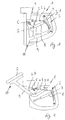
- FIG. 1 and 2 is a detail of an example of a tall cabinet, for example, shown for installation in a kitchen furniture front, which generally bears the reference numeral 1.
- This tall cabinet has a furniture door 2, which in the staging after Fig. 1 closes the cabinet, however, in Fig. 2 is raised or raised.
- a furniture hinge generally numbered 3, is provided, which has two hinge levers 3.1 and 3.2 in the illustrated embodiments.
- the hinge lever 3.2 has in this example of a high cabinet end a cam 4 with an eccentric 5, over which an at least partially flexible trained tension band 6 is guided, which engages the gate member 7.
- a cylinder 8 is still provided.
- About the link plate 4 and the drawstring can represent different closing and opening forces during the opening and closing movement of the furniture door.
- hinge lever 3.1 engages a hinge arm 9, which is connected to the generally numbered with 10 fastening device.
- the mounting arm is welded to the fastening device 10, for example.
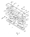
- the fastening device is formed in several parts with substantially plate-shaped bodies and has a base plate 11 and a cap-shaped connector 12 and interposed Verstelloasaplatten 13 and 14.
- the cap-shaped connector 12 is preferably welded to the mounting arm 9.
- the base plate 11, the adjusting body 13 and the adjusting body 14 are preassembled to a total of 15 numbered body with a corresponding basic setting of the parts to each other, the base plate 11 of the body 15 is preferably attached to the furniture door 2. It is of course possible to connect the preassembled structural unit of the basic body 15 to the fastening arm 9 and to fix the connecting piece 12 to the furniture door 2.
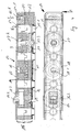
- the connector 12 has In addition, an opening 12.2, which isteurgreifbar by a detent pawl 14.2 of Verstelloasaplatte 14 and after appropriate latching above the housing surface of the connecting piece 12 and the body 15 together with the connecting piece 12 together with the connecting webs 12.1 and the attachment lug 14.1 connects (Fig ).
- the base plate 11 and the VerstellConsequentlyplatten 13 and 14 are by riveting, e.g. at 11.1, 13.1 and 14.3, and at other appropriate locations, to the preassembled unit.
- adjusting means in the form of adjusting wheels 16, 17 and 18 are provided.
- the adjusting wheels 16, 17 and 18 may be self-locking.
- the adjusting wheel 16 serves to adjust the furniture door in the longitudinal direction of the plate parts, according to the arrow 16.1 in Fig. 3 ,
- the adjusting wheel 16 on its side facing the base plate 11 a helical, groove-shaped recess 16.2, in which a pin-shaped pin 19 of the base plate 11 engages.
- the Verstell stressesplatte is moved according to the course of the spiral groove to the left or right, depending on the direction in which the adjusting 16 is moved, whereupon the base plate 11 and associated with this furniture door 2 depending on Direction of rotation of the adjusting wheel 16 in the longitudinal direction of the base body 15 is moved to the left or right.
- the adjusting wheel 17 is for an adjustment of the furniture door 2 at right angles to the furniture door level and therefore also at right angles to Responsible longitudinal direction of the plate elements, whereby a tilt adjustment of the door is accompanied according to the arrow 17.1 in Fig. 3 ,
- the adjusting which is designed as Verstellradschraube, a thread 17.2 and a head end 17.3, with which the adjustment is fixed in position on the base plate 11 is arranged.
- the parts can be set without tools to each other by simple locking.
- the connecting piece 10th projects beyond the next adjacent plate, so the VerstellConsequentlyplatte 14, to where the hand wheels 16, 17, 18 exit from the main body 15.
Landscapes
- Engineering & Computer Science (AREA)
- Mechanical Engineering (AREA)
- Hinges (AREA)
Description
- Die Erfindung bezieht sich auf eine Befestigungsvorrichtung zur Verbindung eines schwenkbaren Möbelteils, beispielsweise einer auf- und absenkbaren Möbeltür eines Küchenschrankmöbels, mit einem Befestigungsarm eines an einem Möbelkorpus abgestützten, zumindest einen Scharnierhebel aufweisenden Möbelscharniers, mit einem Grundkörper und einem an diesem festlegbaren Verbindungsstück, wobei über den Grundkörper und das Verbindungsstück die Möbeltür und der Befestigungsarm aneinander festlegbar sind und dazu der Grundkörper entweder an der Möbeltür oder dem Befestigungsarm und das Verbindungsstück an dem nicht mit dem Grundkörper verbundenen anderen Teil (Möbeltür oder Befestigungsarm) angebunden sind und wobei der Grundkörper zur Lagejustierung der Möbeltür gegenüber dem Möbelkorpus zumindest eine Verstelleinrichtung aufweist, über die orthogonal und/oder parallel zur Ebene der Möbeltür eine Lagejustierung der Möbeltür gegenüber dem Möbelkorpus durchführbar ist und wobei der Grundkörper als mehrteiliges, zur Lagejustierung der Möbeltür entvormontiertes, voreinstellbares Bauteil ausgebildet ist.
- Aus der
EP 0 979 917 A ist eine Befestigungssvorrichtung der eingangs genannten Art bekannt mit einem Scharnier mit einem werkzeuglos mittels eines Zwischenstückes an einer Grundplatte zu befestigenden Scharnierarm, wobei mittels Verstellrädern die Position des Scharnierarmes zur Grundplatte zu verstellen ist. Der Tragarm trägt alle Verstellmittel, die für eine Lagejustierung einer Möbeltür gegenüber einem Möbelkorpus erforderlich sind, nicht jedoch die Grundplatte selbst. Somit kann der Grundkörper auch nicht als voreingestelltes und endmontiertes Grundkörperteil zur Verfügung gestellt werden. - Aus der
WO2007/045631 ist eine Befestigungsvorrichtung für eine Schwenkmöbeltür an einem Möbelkorpus bekannt, bei der Scharnierhebel über eine Grundplatte mit der Möbeltür zu verbinden ist. Die Grundplatte weist zwei Verstellmittel in Gestalt von zwei Nocken auf, um eine Lagefixierung durchführen zu können. Dies kann jedoch nur in zwei Ebenen erfolgen, nicht jedoch in drei Ebenen. Die Nocken sind auch nur über Werkzeuge in eine veränderte Position zu bringen. - Somit ist insgesamt nachteilig, dass die Befestigung der Befestigungseinrichtungen nur mit Werkzeugen zu vollziehen ist. Ist die Möbeltür lagezujustieren, fordert dies auch den Einsatz von Werkzeugen. Insbesondere ist dies bei den bekannten Befestigungseinrichtungen nur mit erhöhtem Aufwand möglich, um nach einer Erstmontage zu einem späteren Zeitpunkt die Möbeltür nachzujustieren.
- Es ist Aufgabe der vorliegenden Erfindung, eine Befestigungseinrichtung der vorgenannten Art zur Verfügung zu stellen, mit der möglichst werkzeuglos eine Möbeltür mit dem Möbelscharnier zu verbinden ist und bei dem es ebenfalls möglich ist, auch im Nachhinein ohne die Montage von Teilen eine Lagejustierung der Möbeltür vorzunehmen.
- Zur Lösung dieser Aufgabe zeichnet sich die Befestigungsvorrichtung der eingangs genannten Art durch die im Patentanspruch 1 angegebenen Merkmale aus.
- Damit ist eine Befestigungseinrichtung zur Verbindung eines schwenkbaren Möbelteils mit dem Befestigungsarm eines Möbelscharniers zur Verfügung gestellt, mit der das schwenkbare Möbelteil werkzeuglos mit dem Verbindungsarm des Scharniers verbindbar ist und bei der auch im Nachhinein noch die Möbeltür durch die Verstellmittel, die über zumindest eine Körperfläche des Grundkörpers hinausragen, zu verstellen ist. Auch dies kann werkzeuglos erfolgen, indem die Verstellmittel als Hand- bzw. Verstellräder ausgebildet sind, die eine Öffnung eines Grundkörpers durchsetzen und auch im Nachhinein von außen für eine Bedienperson zugänglich sind.
- Der Grundkörper und das Verbindungsstück der Befestigungseinrichtung können entweder an der Möbeltür oder aber an dem Befestigungsarm vorgesehen sein. In aller Regel wird es jedoch so sein, daß der Grundkörper an der Möbeltür anzubinden ist, beispielsweise durch eine Schraubverbindung und daß das Verbindungsstück mit dem Verbindungsarm verschweißt ist. Durch z.B. eine einfache Verrastung sind dann Grundkörper und Verbindungsstück aneinander festzulegen, womit in außerordentlich zeitsparender Weise das schwenkbare Möbelteil an den Möbelkörper bzw. dessen Scharnier anzubinden ist. Der Grundkörper selbst ist als mehrteiliges vormontiertes Bauteil zur Verfügung zu stellen, wobei dessen Grundplatte und Verstellkörperplatten über z.B. eine Niet- oder Schraubverbindung mit dazwischen liegenden Verstellmitteln und zugehörigen Teilen komplettiert an dem schwenkbaren Möbelteil zu befestigen ist. Nach entsprechender Verrastung mit dem Verbindungsstück kann die Feinjustierung der Möbeltür ohne den Einsatz von Werkzeugen erfolgen.
- Hinsichtlich weiterer vorteilhafter Ausgestaltungen der Erfindung wird auf weitere Unteransprüche, die nachfolgende Beschreibung und die Zeichnung verwiesen. In der Zeichnung zeigen:
- Fig. 1 und 2
- jeweils in einer perspektivischen Seitenansicht ausschnittsweise einen Küchenhochschrank mit einer aufschwenkbaren Schranktür, die über ein Ausführungsbeispiel einer Befestigungseinrichtung mit einem am Möbelkorpus angebrachten Möbelscharnier verbunden ist,
- Fig. 3
- in perspektivischer Explosivdarstellung ein Ausführungsbeispiel einer Befestigungseinrichtung nach der Erfindung,
- Fig. 4
- eine Draufsicht auf das Ausführungsbeispiel nach
Fig. 3 , und - Fig. 5
- eine Schnittdarstellung gemäß der Schnittlinie (strichpunktiert) A-A in
Fig. 4 . - In der Zeichnung sind grundsätzlich gleichwirkende Teile mit übereinstimmenden Bezugsziffern versehen.
- In den zeichnerischen Darstellungen nach den
Fig. 1 und 2 ist ausschnittsweise ein Beispiel eines Hochschrankes z.B. zum Einbau in eine Küchenmöbelfront dargestellt, der allgemein die Bezugsziffer 1 trägt. Dieser Hochschrank hat eine Möbeltür 2, die in der Darstelung nachFig. 1 den Schrank verschließt, hingegen inFig. 2 aufgeschwenkt bzw. angehoben ist. Dazu ist ein allgemein mit 3 beziffertes Möbelscharnier vorgesehen, das in den dargestellten Ausführungsbeispielen zwei Scharnierhebel 3.1 und 3.2 hat. Der Scharnierhebel 3.2 hat bei diesem Beispiel eines Hochschrankes endseitig eine Kurvenscheibe 4 mit einem Exzenterstück 5, über den ein zumindest bereichsweise flexibel ausgebildetes Zugband 6 geführt ist, das an dem Kulissenteil 7 angreift. An diesem Kulissenteil 7 ist noch ein Zylinder 8 vorgesehen. Über die Kulissenscheibe 4 und das Zugband lassen sich während der Öffnungs- und Schließbewegung der Möbeltür verschiedene Schließ- und Öffnungskräfte darstellen. - An dem Scharnierhebel 3.1 greift ein Scharnierarm 9 an, der mit der allgemein mit 10 bezifferten Befestigungseinrichtung verbunden ist. Der Befestigungsarm ist z.B. mit der Befestigungseinrichtung 10 verschweißt.
- Wie aus den
Fig. 3 bis 5 näher hervorgeht, ist die Befestigungseinrichtung mehrteilig mit im wesentlichen plattenförmigen Körpern ausgebildet und hat eine Grundplatte 11 sowie ein kappenförmiges Verbindungsstück 12 sowie dazwischen angeordnete Verstellkörperplatten 13 und 14. Das kappenförmige Verbindungsstück 12 ist dabei bevorzugterweise mit dem Befestigungsarm 9 verschweißt. Die Grundplatte 11, der Verstellkörper 13 sowie der Verstellkörper 14 sind zu einem ingesamt mit 15 bezifferten Grundkörper vormontiert mit einer entsprechenden Grundeinstellung der Teile zueinander, wobei die Grundplatte 11 des Grundkörpers 15 bevorzugterweise an der Möbeltür 2 befestigt wird. Es ist selbstverständlich möglich, die vormontierte Baueinheit des Grundkörpers 15 an den Befestigungsarm 9 anzubinden und das Verbindungsstück 12 an der Möbeltür 2 festzulegen. Wesentlich ist, daß die vormontierte Grundkörpereinheit 15 und das Verbindungsstück 12 werkzeuglos aneinander festzulegen sind, und zwar durch eine einfache Verrastung und ein Untergreifen von Befestigungsansätzen 14 an der dem Verbindungsstück 12 benachbarten Verstellkörperplatte 14 durch entsprechende Verbindungsstege 12.1 an dem Verbindungsstück 12. Das Verbindungsstück 12 weist zudem eine Öffnung 12.2 auf, die von einer Rastklinke 14.2 der Verstellkörperplatte 14 durchgreifbar ist und nach entsprechender Verrastung oberhalb der Gehäuseoberfläche des Verbindungsstückes 12 anliegt und den Grundkörper 15 insgesamt mit dem Verbindungsstück 12 zusammen mit den Verbindungsstegen 12.1 und dem Befestigungsansatz 14.1 verbindet (Fig. 5). - Die Grundplatte 11 sowie die Verstellkörperplatten 13 und 14 sind durch Nietverbindungen z.B. bei 11.1, 13.1 und 14.3 sowie an anderen geeigneten Stellen zu der vormontierten Baueinheit zusammenzufügen.
- Zur Lagejustierung der Möbeltür bzw. zu deren Verstellung und zur Verstellung der einzelnen Platten des Grundkörpers 15 mitsamt dem Verbindungsstück 12 relativ zueinander bzw. relativ zur Grundplatte 11 sind Verstellmittel in Gestalt von Verstellrädern 16, 17 und 18 vorgesehen.
- Die Verstellräder 16, 17 und 18 können selbsthemmend ausgebildet sein. Das Verstellrad 16 dient dazu, die Möbeltür in Längsrichtung der Plattenteile zu verstellen, entsprechend der Pfeildarstellung 16.1 in
Fig. 3 . Dazu hat das Verstellrad 16 an seiner der Grundplatte 11 zugewandten Seite eine spiralförmige, nutenförmige Ausnehmung 16.2, in die ein zapfenförmiger Stift 19 der Grundplatte 11 eingreift. Durch eine Bewegung des Hand- bzw. Verstellrades 16 wird die Verstellkörperplatte entsprechend dem Verlauf der spiralförmigen Nut nach links oder rechts bewegt, je nachdem, in welche Richtung das Verstellrad 16 bewegt wird, woraufhin die Grundplatte 11 und die mit dieser verbundenen Möbeltür 2 je nach Verdrehrichtung des Verstellrades 16 in Längsrichtung des Grundkörpers 15 nach links oder rechts bewegt wird. - Der entsprechende Bewegungsspielraum unterhalb des Verstellkörpers ist dazu vorhanden, wie Fig. 5 im einzelnen zeigt. Das Verstellrad 17 ist für eine Verstellung der Möbeltür 2 rechtwinklig zur Möbeltürebene und mithin auch rechtwinklig zur Längsrichtung der Plattenelemente zuständig, womit eine Neigungsverstellung der Tür einhergeht entsprechend der Pfeildarstellung 17.1 in
Fig. 3 . Dazu hat das Verstellrad, das als Verstellradschraube ausgebildet ist, ein Gewinde 17.2 und ein Kopfende 17.3, mit dem das Verstellrad lagefixiert an der Grundplatte 11 angeordnet ist. Durch ein Drehen der Verstellradschraube 17 wird die Grundplatte 11 von dem Verstellkörper 13 und den sonstigen Teilen des Grundkörpers, des Verbindungsstückes 12 und letztendlich des Scharniers 3 wegbewegt und kann mithin eine geneigte Lage einnehmen, wie diese durch die geneigte Linie 20 in Fig. 5 angedeutet ist. - Das Verstellmittel 18, das zwischen den Verstellkörperplatten 13 und 14 vorgesehen ist, ist analog ausgebildet wie das Verstellrad 16 und hat ebenfalls eine spiralförmige Nut 18.1, in die ein Zapfen 21 eingreift. Mit der Bewegung dieses Verstellrades kann eine Querverstellung entsprechend der Pfeile 22 in
Fig. 3 vorgenommen werden. - Insgesamt ist damit eine Befestigungseinrichtung zur Verfügung gestellt, deren Teile sich werkzeuglos aneinander festlegen lassen durch einfache Verrastung. Durch das Überstehen der Verstellräder über die seitliche Erstreckung, d.h. die Längsseitenkanten des Grundkörpers (sh. die Draufsicht nach
Fig. 4 ), und zwar zu beiden Seiten des Grundkörpers 15 und des Verbindungsstückes 10, kann auch nach Verrastung des Verbindungsstückes 10 mit dem Grundkörper 15 eine Lagejustierung der Möbeltür durch eine einfache Bedienung der Verstell- bzw. Handräder 16, 17, und 18 vorgenommen werden, und zwar ebenfalls werkzeuglos. Das Verbindungsstück 10 überragt dabei die nächstbenachbarte Platte, also die Verstellkörperplatte 14, bis dorthin, wo die Handräder 16, 17, 18 aus dem Grundkörper 15 austreten.
Claims (12)
- Befestigungsvorrichtung (10) zur Verbindung eines schwenkbaren Möbelteils (2), beispielsweise einer auf- und absenkbaren Möbeltür eines Küchenschrankmöbels, mit einem Befestigungsarm (9) eines an einem Möbelkorpus abgestützten, zumindest einen Scharnierhebel (3.1, 3.2) aufweisenden Möbelscharniers (3), mit einem Grundkörper (15) und einem an diesem festlegbaren Verbindungsstück (12), wobei über den Grundkörper (15) und das Verbindungsstück (12) die Möbeltür (2) und der Befestigungsarm (9) aneinander festlegbar sind und dazu der Grundkörper (15) entweder an der Möbeltür (2) oder dem Befestigungsarm (9) und das Verbindungsstück (12) an dem nicht mit dem Grundkörper (15) verbundenen anderen Teil (Möbeltür (2) oder Befestigungsarm (9)) angebunden sind und wobei der Grundkörper (15) zur Lagejustierung der Möbeltür (2) gegenüber dem Möbelkorpus zumindest eine Verstelleinrichtung aufweist, über die orthogonal und/oder parallel zur Ebene der Möbeltür (2) eine Lagejustierung der Möbeltür (2) gegenüber dem Möbelkorpus durchführbar ist und wobei der Grundkörper als mehrteiliges, zur Lagejustierung der Möbeltür (2) endvormontiertes, voreinstellbares Bauteil ausgebildet ist, dadurch gekennzeichnet, dass der Grundkörper (15) eine Grundplatte (11) und zwei oberhalb der Grundplatte (11) angeordnete Verstellkörperplatten (13, 14) aufweist, wobei ein über zumindest eine Seite des Grundkörpers (15) ragendes Verstellmittel (17) zwischen der Grundplatte (11) und der dieser direkt benachbarten Verstellkörperplatte (13) zur Verstellung der Möbeltür (2) quer zu ihrer Längsebene (Neigungsverstellung) vorgesehen ist und zwischen den beiden Verstellkörperplatten (13, 14) ein weiteres Verstellmittel (18) vorgesehen ist, und dass das Verbindungsstück (12) ohne Verstellmittel an der Möbeltür (2) oder dem Befestigungsarm (19) befestigt und ohne Verstellmittel mit dem Grundkörper (15) verbindbar ist, wobei der Grundkörper (15) alle zur Lagejustierung der Möbeltür (2) gegenüber dem Möbelkorpus vorgesehenen Verstellmittel (16, 17, 18) aufweist und zumindest eines dieser Verstellmittel (16, 17, 18) über eine Oberfläche des Grundkörpers (15) zur Handbedienung vorsteht.
- Befestigungsvorrichtung nach Anspruch 1, dadurch gekennzeichnet, dass das Verbindungsstück (12) werkzeuglos mit dem Grundkörper (15) verrastbar und/oder entrastbar ist.
- Befestigungsvorrichtung nach Anspruch 1 oder 2, dadurch gekennzeichnet, dass zwischen der Grundplatte (11) und der ersten Verstellkörperplatte (13) ein Verstellmittel (16) vorgesehen ist zur Verstellung der Möbeltür (2) in Längsrichtung des Grundkörpers (15).
- Befestigungsvorrichtung nach Anspruch 3, dadurch gekennzeichnet, dass das Verstellmittel (16) zur Verstellung der Möbeltür (2) in Längsrichtung (16.1) des Grundkörpers (15) als Verstellrad ausgebildet ist, das eine spiralförmige Nut (16.2) aufweist, in die ein zapfenförmiges, an der Grundplatte (11) vorgesehenes Verstellelement (19) eingreift.
- Befestigungsvorrichtung nach einem der Ansprüche 1 bis 6, dadurch gekennzeichnet, dass zwischen den beiden Verstellkörperplatten (13, 14) ein Verstellmittel (18) zur Verstellung der Möbeltür (2) quer zur Längsrichtung (6.1) des Grundkörpers (15) vorgesehen ist.
- Befestigungsvorrichtung nach Anspruch 5, dadurch gekennzeichnet, dass das Verstellmittel (18) zur Verstellung der Möbeltür (2) in Querrichtung (22) des Grundkörpers (15) als Verstellrad ausgebildet ist, in das einenends eine Verstellkörperplatte (12) eingreift und an ihrer der anderen Verstellkörperplatte (13) zugewandten Seite eine spiralförmige Aufnahmenut (18.1) aufweist, in die ein zapfenförmiges Verstellelement (21) angreift, das an der anderen Verstellkörperplatte (13) vorgesehen ist.
- Befestigungsvorrichtung nach einem der Ansprüche 1 bis 6, dadurch gekennzeichnet, dass das Verstellmittel (17) zur Neigungsverstellung als Verstellradschraube ausgebildet, lagefixiert an der Grundplatte (11) angeordnet sowie mit seinem Gewindebereich (17.2) mit einem Hebebereich (23) der Verstellkörperplatten (13) verbindbar ist, über das die Grundplatte (11) von den Verstellkörperplatten (13, 14) und dem Verbindungsstück (12) weg bewegbar ist.
- Befestigungsvorrichtung nach einem der Ansprüche 1 bis 7, dadurch gekennzeichnet, dass an dem Verbindungsstück (12) Befestigungsstege (12.1) vorgesehen sind, die im montierten Zustand der Teile Befestigungsansätze (14.1) des Grundkörpers (15) zur werkzeuglosen Befestigung des Verbindungsstückes (12) an dem Grundkörper (15) untergreifen und dass die dem Verbindungsstück (12) zugewandte Verstellkörperplatte (15) zumindest einen Rastansatz (14.2) hat, der eine Öffnung (12.2) im Verbindungsstück (12) durchgreift und mit dem Verbindungsstück (12) verrastbar ist.
- Befestigungsvorrichtung nach einem der Ansprüche 1 bis 8, dadurch gekennzeichnet, dass die Verstellmittel (16, 17, 18) als Handräder ausgebildet sind und die Seitenflächen des Grundkörpers (15) an zwei Längsseiten überragen.
- Befestigungsvorrichtung nach einem der Ansprüche 1 bis 9, dadurch gekennzeichnet, dass die Verstellmittel (16, 17, 18) selbsthemmend ausgebildet sind.
- Befestigungsvorrichtung nach einem der Ansprüche 1 bis 10, dadurch gekennzeichnet, dass das Verbindungsstück (12) im Bereich des Grundkörpers (15) nur die diesem benachbart angeordnete Verstellkörperplatte (14) übergreift.
- Befestigungsvorrichtung nach einem der Ansprüche 1 bis 11, dadurch gekennzeichnet, dass die Grundplatte (11) und die Verstellkörperplatten (13, 14) über eine Schraub- und/oder Nietverbindung zur Ausbildung einer vormontierten Grundkörperbaueinheit aneinander festlegbar sind.
Priority Applications (1)
| Application Number | Priority Date | Filing Date | Title |
|---|---|---|---|
| PL08008391T PL1990493T3 (pl) | 2007-05-07 | 2008-05-03 | Urządzenie mocujące wychylnej części mebla |
Applications Claiming Priority (1)
| Application Number | Priority Date | Filing Date | Title |
|---|---|---|---|
| DE102007021785A DE102007021785B4 (de) | 2007-05-07 | 2007-05-07 | Befestigungsvorrichtung |
Publications (2)
| Publication Number | Publication Date |
|---|---|
| EP1990493A1 EP1990493A1 (de) | 2008-11-12 |
| EP1990493B1 true EP1990493B1 (de) | 2015-10-14 |
Family
ID=39638741
Family Applications (1)
| Application Number | Title | Priority Date | Filing Date |
|---|---|---|---|
| EP08008391.8A Not-in-force EP1990493B1 (de) | 2007-05-07 | 2008-05-03 | Befestigungseinrichtung eines schwenkbaren Möbelteils |
Country Status (5)
| Country | Link |
|---|---|
| EP (1) | EP1990493B1 (de) |
| DE (1) | DE102007021785B4 (de) |
| DK (1) | DK1990493T3 (de) |
| ES (1) | ES2557169T3 (de) |
| PL (1) | PL1990493T3 (de) |
Cited By (2)
| Publication number | Priority date | Publication date | Assignee | Title |
|---|---|---|---|---|
| DE102017126367A1 (de) | 2017-11-10 | 2019-05-16 | Hettich-Oni Gmbh & Co. Kg | Klappenbeschlag für ein Möbel, Seitenwand eines Möbelkorpus und Möbel mit einer Seitenwand |
| RU2775117C2 (ru) * | 2017-11-10 | 2022-06-28 | ХЕТТИХ-ОНИ ГмбХ унд Ко. КГ | Фурнитура створки для предмета мебели, боковая стенка корпуса мебели и предмет мебели, имеющий боковую стенку |
Citations (1)
| Publication number | Priority date | Publication date | Assignee | Title |
|---|---|---|---|---|
| WO2007045631A1 (en) * | 2005-10-18 | 2007-04-26 | Arturo Salice S.P.A. | Device for opening and retaining rotating leaf door |
Family Cites Families (3)
| Publication number | Priority date | Publication date | Assignee | Title |
|---|---|---|---|---|
| AT341907B (de) * | 1974-02-26 | 1978-03-10 | Blum Gmbh | Tiefeinstellbares scharnier, insbesondere fur mobelturflugel, mit einer grundplatte |
| AT1214U1 (de) * | 1995-12-18 | 1996-12-27 | Blum Gmbh Julius | Scharnier |
| AT407277B (de) * | 1998-08-11 | 2001-02-26 | Blum Gmbh Julius | Scharnier |
-
2007
- 2007-05-07 DE DE102007021785A patent/DE102007021785B4/de not_active Withdrawn - After Issue
-
2008
- 2008-05-03 EP EP08008391.8A patent/EP1990493B1/de not_active Not-in-force
- 2008-05-03 ES ES08008391.8T patent/ES2557169T3/es active Active
- 2008-05-03 PL PL08008391T patent/PL1990493T3/pl unknown
- 2008-05-03 DK DK08008391.8T patent/DK1990493T3/en active
Patent Citations (1)
| Publication number | Priority date | Publication date | Assignee | Title |
|---|---|---|---|---|
| WO2007045631A1 (en) * | 2005-10-18 | 2007-04-26 | Arturo Salice S.P.A. | Device for opening and retaining rotating leaf door |
Cited By (4)
| Publication number | Priority date | Publication date | Assignee | Title |
|---|---|---|---|---|
| DE102017126367A1 (de) | 2017-11-10 | 2019-05-16 | Hettich-Oni Gmbh & Co. Kg | Klappenbeschlag für ein Möbel, Seitenwand eines Möbelkorpus und Möbel mit einer Seitenwand |
| WO2019091967A1 (de) | 2017-11-10 | 2019-05-16 | Hettich-Oni Gmbh & Co. Kg | Klappenbeschlag für ein möbel, seitenwand eines möbelkorpus und möbel mit einer seitenwand |
| US11319737B2 (en) | 2017-11-10 | 2022-05-03 | Hettich-Oni Gmbh & Co. Kg | Flap fitting for a piece of furniture, side wall of a body of a piece of furniture and piece of furniture comprising a side wall |
| RU2775117C2 (ru) * | 2017-11-10 | 2022-06-28 | ХЕТТИХ-ОНИ ГмбХ унд Ко. КГ | Фурнитура створки для предмета мебели, боковая стенка корпуса мебели и предмет мебели, имеющий боковую стенку |
Also Published As
| Publication number | Publication date |
|---|---|
| PL1990493T3 (pl) | 2016-04-29 |
| EP1990493A1 (de) | 2008-11-12 |
| DE102007021785B4 (de) | 2009-06-04 |
| DE102007021785A1 (de) | 2008-11-20 |
| DK1990493T3 (en) | 2015-12-14 |
| ES2557169T3 (es) | 2016-01-22 |
Similar Documents
| Publication | Publication Date | Title |
|---|---|---|
| EP1647663B1 (de) | Halter für ein plattenförmiges Element | |
| EP1190891B1 (de) | Höhenverstellbares Untergestell eines Kraftfahrzeugsitzes mit zwei Seitenteilen | |
| EP1812674B1 (de) | Stellantrieb | |
| DE4334331A1 (de) | Querträger für Dachlasten an einem mit einer Dachreling ausgestatteten Kraftwagen | |
| EP0704595A1 (de) | Einstellvorrichtung für eine mit einer Fensterheberanordnung zusammenwirkende, rahmenlos ausgebildete Türfensterscheibe eines Kraftfahrzeuges | |
| EP3108864B1 (de) | Faltbarer rollstuhl | |
| EP0008753B1 (de) | Fussstütze | |
| DE19812490C2 (de) | Einrichtung zur lösbaren Befestigung eines Sitzes, insbesondere Fahrzeugsitzes, an einer längsverlaufenden Schiene | |
| DE2721539A1 (de) | Fahrzeugsitz | |
| EP1990493B1 (de) | Befestigungseinrichtung eines schwenkbaren Möbelteils | |
| DE19820711A1 (de) | Vorrichtung zum Dämpfen der Endbewegung eines Verdeck-Frontspriegels | |
| EP1781881B1 (de) | Montageplatte zur verstellbaren halterung von möbelscharnieren am korpus von möbelstücken | |
| EP1764138B1 (de) | Vorrichtung zum Positionieren einer zwei Skibindungsteile aufweisenden Skibindung auf einem Ski | |
| EP2186445B1 (de) | Untermatratze für ein Bett | |
| DE2216438A1 (de) | Fotografisches stativ | |
| EP0711632A1 (de) | Spannvorrichtung | |
| DE102004034148B4 (de) | Gasheizstrahler in Form eines Terrassenstrahlers sowie schwenkbare Baugruppe hierzu | |
| EP2287427B1 (de) | Einachsscharnier | |
| DE19704330C2 (de) | Möbelbeschlag | |
| DE10244048B4 (de) | Vorrichtung zum Ausrichten einer Fahrzeugtür, insbesondere einer Kraftfahrzeugtür | |
| DE202007000136U1 (de) | Jalousie | |
| DE20200499U1 (de) | Möbelbeschlag zur Sitzhöhen- und Sitztiefenverstellung | |
| DE20313635U1 (de) | Band für Türen, Fenster o.dgl. | |
| EP1724427A2 (de) | Vorrichtung zur Einstellung der Lage einer Führungsschiene eines Fensterhebers | |
| DE19746806C1 (de) | Beschlag zur stufenweisen Neigungsverstellung eines Kopf- oder Fußteiles eines Sitz- oder Liegemöbels |
Legal Events
| Date | Code | Title | Description |
|---|---|---|---|
| PUAI | Public reference made under article 153(3) epc to a published international application that has entered the european phase |
Free format text: ORIGINAL CODE: 0009012 |
|
| 17P | Request for examination filed |
Effective date: 20080905 |
|
| AK | Designated contracting states |
Kind code of ref document: A1 Designated state(s): AT BE BG CH CY CZ DE DK EE ES FI FR GB GR HR HU IE IS IT LI LT LU LV MC MT NL NO PL PT RO SE SI SK TR |
|
| AX | Request for extension of the european patent |
Extension state: AL BA MK RS |
|
| 17Q | First examination report despatched |
Effective date: 20081218 |
|
| AKX | Designation fees paid |
Designated state(s): AT BE BG CH CY CZ DE DK EE ES FI FR GB GR HR HU IE IS IT LI LT LU LV MC MT NL NO PL PT RO SE SI SK TR |
|
| RAP1 | Party data changed (applicant data changed or rights of an application transferred) |
Owner name: KESSEBOEHMER HOLDING E.K. |
|
| GRAP | Despatch of communication of intention to grant a patent |
Free format text: ORIGINAL CODE: EPIDOSNIGR1 |
|
| INTG | Intention to grant announced |
Effective date: 20150610 |
|
| RIN1 | Information on inventor provided before grant (corrected) |
Inventor name: TERLTHOERSTER, DIRK Inventor name: DIE ANDERE ERFINDER HABEN AUF IHRE NENNUNG VERZICH |
|
| GRAS | Grant fee paid |
Free format text: ORIGINAL CODE: EPIDOSNIGR3 |
|
| GRAA | (expected) grant |
Free format text: ORIGINAL CODE: 0009210 |
|
| AK | Designated contracting states |
Kind code of ref document: B1 Designated state(s): AT BE BG CH CY CZ DE DK EE ES FI FR GB GR HR HU IE IS IT LI LT LU LV MC MT NL NO PL PT RO SE SI SK TR |
|
| REG | Reference to a national code |
Ref country code: GB Ref legal event code: FG4D Free format text: NOT ENGLISH |
|
| REG | Reference to a national code |
Ref country code: AT Ref legal event code: REF Ref document number: 755228 Country of ref document: AT Kind code of ref document: T Effective date: 20151015 Ref country code: CH Ref legal event code: EP |
|
| REG | Reference to a national code |
Ref country code: IE Ref legal event code: FG4D Free format text: LANGUAGE OF EP DOCUMENT: GERMAN |
|
| REG | Reference to a national code |
Ref country code: DE Ref legal event code: R096 Ref document number: 502008013470 Country of ref document: DE |
|
| REG | Reference to a national code |
Ref country code: DK Ref legal event code: T3 Effective date: 20151209 |
|
| REG | Reference to a national code |
Ref country code: SE Ref legal event code: TRGR |
|
| REG | Reference to a national code |
Ref country code: ES Ref legal event code: FG2A Ref document number: 2557169 Country of ref document: ES Kind code of ref document: T3 Effective date: 20160122 |
|
| REG | Reference to a national code |
Ref country code: NL Ref legal event code: FP |
|
| REG | Reference to a national code |
Ref country code: LT Ref legal event code: MG4D |
|
| REG | Reference to a national code |
Ref country code: NO Ref legal event code: T2 Effective date: 20151014 |
|
| PG25 | Lapsed in a contracting state [announced via postgrant information from national office to epo] |
Ref country code: IS Free format text: LAPSE BECAUSE OF FAILURE TO SUBMIT A TRANSLATION OF THE DESCRIPTION OR TO PAY THE FEE WITHIN THE PRESCRIBED TIME-LIMIT Effective date: 20160214 Ref country code: HR Free format text: LAPSE BECAUSE OF FAILURE TO SUBMIT A TRANSLATION OF THE DESCRIPTION OR TO PAY THE FEE WITHIN THE PRESCRIBED TIME-LIMIT Effective date: 20151014 Ref country code: LT Free format text: LAPSE BECAUSE OF FAILURE TO SUBMIT A TRANSLATION OF THE DESCRIPTION OR TO PAY THE FEE WITHIN THE PRESCRIBED TIME-LIMIT Effective date: 20151014 |
|
| REG | Reference to a national code |
Ref country code: FR Ref legal event code: PLFP Year of fee payment: 9 |
|
| PG25 | Lapsed in a contracting state [announced via postgrant information from national office to epo] |
Ref country code: LV Free format text: LAPSE BECAUSE OF FAILURE TO SUBMIT A TRANSLATION OF THE DESCRIPTION OR TO PAY THE FEE WITHIN THE PRESCRIBED TIME-LIMIT Effective date: 20151014 Ref country code: PT Free format text: LAPSE BECAUSE OF FAILURE TO SUBMIT A TRANSLATION OF THE DESCRIPTION OR TO PAY THE FEE WITHIN THE PRESCRIBED TIME-LIMIT Effective date: 20160215 |
|
| REG | Reference to a national code |
Ref country code: DE Ref legal event code: R082 Ref document number: 502008013470 Country of ref document: DE Representative=s name: BUSSE & BUSSE PATENT- UND RECHTSANWAELTE PARTN, DE Ref country code: DE Ref legal event code: R081 Ref document number: 502008013470 Country of ref document: DE Owner name: KESSEBOEHMER HOLDING KG, DE Free format text: FORMER OWNER: KESSEBOEHMER HOLDING E.K., 49152 BAD ESSEN, DE |
|
| REG | Reference to a national code |
Ref country code: DE Ref legal event code: R097 Ref document number: 502008013470 Country of ref document: DE |
|
| PLBE | No opposition filed within time limit |
Free format text: ORIGINAL CODE: 0009261 |
|
| STAA | Information on the status of an ep patent application or granted ep patent |
Free format text: STATUS: NO OPPOSITION FILED WITHIN TIME LIMIT |
|
| PG25 | Lapsed in a contracting state [announced via postgrant information from national office to epo] |
Ref country code: RO Free format text: LAPSE BECAUSE OF FAILURE TO SUBMIT A TRANSLATION OF THE DESCRIPTION OR TO PAY THE FEE WITHIN THE PRESCRIBED TIME-LIMIT Effective date: 20151014 Ref country code: BE Free format text: LAPSE BECAUSE OF NON-PAYMENT OF DUE FEES Effective date: 20160531 Ref country code: EE Free format text: LAPSE BECAUSE OF FAILURE TO SUBMIT A TRANSLATION OF THE DESCRIPTION OR TO PAY THE FEE WITHIN THE PRESCRIBED TIME-LIMIT Effective date: 20151014 Ref country code: SK Free format text: LAPSE BECAUSE OF FAILURE TO SUBMIT A TRANSLATION OF THE DESCRIPTION OR TO PAY THE FEE WITHIN THE PRESCRIBED TIME-LIMIT Effective date: 20151014 |
|
| REG | Reference to a national code |
Ref country code: AT Ref legal event code: HC Ref document number: 755228 Country of ref document: AT Kind code of ref document: T Owner name: KESSEBOEHMER HOLDING KG, DE Effective date: 20160802 |
|
| 26N | No opposition filed |
Effective date: 20160715 |
|
| REG | Reference to a national code |
Ref country code: NL Ref legal event code: PD Owner name: KESSEBOEHMER HOLDING KG; DE Free format text: DETAILS ASSIGNMENT: VERANDERING VAN EIGENAAR(S), VERANDERING VAN DE JURIDISCHE ENTITEIT; FORMER OWNER NAME: KESSEBOEHMER HOLDING E.K. Effective date: 20160621 |
|
| REG | Reference to a national code |
Ref country code: FR Ref legal event code: CD Owner name: KESSEBOHMER HOLDING KG, DE Effective date: 20160905 |
|
| REG | Reference to a national code |
Ref country code: ES Ref legal event code: PC2A Owner name: KESSEBOEHMER HOLDING KG Effective date: 20161020 |
|
| REG | Reference to a national code |
Ref country code: NO Ref legal event code: CHAD Owner name: KESSEBOEHMER HOLDING KG, DE |
|
| PG25 | Lapsed in a contracting state [announced via postgrant information from national office to epo] |
Ref country code: SI Free format text: LAPSE BECAUSE OF FAILURE TO SUBMIT A TRANSLATION OF THE DESCRIPTION OR TO PAY THE FEE WITHIN THE PRESCRIBED TIME-LIMIT Effective date: 20151014 |
|
| PG25 | Lapsed in a contracting state [announced via postgrant information from national office to epo] |
Ref country code: LU Free format text: LAPSE BECAUSE OF FAILURE TO SUBMIT A TRANSLATION OF THE DESCRIPTION OR TO PAY THE FEE WITHIN THE PRESCRIBED TIME-LIMIT Effective date: 20160503 |
|
| REG | Reference to a national code |
Ref country code: CH Ref legal event code: PL |
|
| PG25 | Lapsed in a contracting state [announced via postgrant information from national office to epo] |
Ref country code: LI Free format text: LAPSE BECAUSE OF NON-PAYMENT OF DUE FEES Effective date: 20160531 Ref country code: CH Free format text: LAPSE BECAUSE OF NON-PAYMENT OF DUE FEES Effective date: 20160531 |
|
| REG | Reference to a national code |
Ref country code: FR Ref legal event code: PLFP Year of fee payment: 10 |
|
| REG | Reference to a national code |
Ref country code: FR Ref legal event code: PLFP Year of fee payment: 11 |
|
| PG25 | Lapsed in a contracting state [announced via postgrant information from national office to epo] |
Ref country code: HU Free format text: LAPSE BECAUSE OF FAILURE TO SUBMIT A TRANSLATION OF THE DESCRIPTION OR TO PAY THE FEE WITHIN THE PRESCRIBED TIME-LIMIT; INVALID AB INITIO Effective date: 20080503 Ref country code: CY Free format text: LAPSE BECAUSE OF FAILURE TO SUBMIT A TRANSLATION OF THE DESCRIPTION OR TO PAY THE FEE WITHIN THE PRESCRIBED TIME-LIMIT Effective date: 20151014 |
|
| PG25 | Lapsed in a contracting state [announced via postgrant information from national office to epo] |
Ref country code: MC Free format text: LAPSE BECAUSE OF FAILURE TO SUBMIT A TRANSLATION OF THE DESCRIPTION OR TO PAY THE FEE WITHIN THE PRESCRIBED TIME-LIMIT Effective date: 20151014 Ref country code: MT Free format text: LAPSE BECAUSE OF FAILURE TO SUBMIT A TRANSLATION OF THE DESCRIPTION OR TO PAY THE FEE WITHIN THE PRESCRIBED TIME-LIMIT Effective date: 20151014 Ref country code: GR Free format text: LAPSE BECAUSE OF FAILURE TO SUBMIT A TRANSLATION OF THE DESCRIPTION OR TO PAY THE FEE WITHIN THE PRESCRIBED TIME-LIMIT Effective date: 20151014 |
|
| PG25 | Lapsed in a contracting state [announced via postgrant information from national office to epo] |
Ref country code: BG Free format text: LAPSE BECAUSE OF FAILURE TO SUBMIT A TRANSLATION OF THE DESCRIPTION OR TO PAY THE FEE WITHIN THE PRESCRIBED TIME-LIMIT Effective date: 20151014 |
|
| PGFP | Annual fee paid to national office [announced via postgrant information from national office to epo] |
Ref country code: NO Payment date: 20190328 Year of fee payment: 12 Ref country code: GB Payment date: 20190327 Year of fee payment: 12 |
|
| PGFP | Annual fee paid to national office [announced via postgrant information from national office to epo] |
Ref country code: NL Payment date: 20190528 Year of fee payment: 12 |
|
| PGFP | Annual fee paid to national office [announced via postgrant information from national office to epo] |
Ref country code: IE Payment date: 20190415 Year of fee payment: 12 Ref country code: DE Payment date: 20190221 Year of fee payment: 12 Ref country code: ES Payment date: 20190605 Year of fee payment: 12 Ref country code: FI Payment date: 20190418 Year of fee payment: 12 Ref country code: IT Payment date: 20190510 Year of fee payment: 12 Ref country code: PL Payment date: 20190402 Year of fee payment: 12 Ref country code: DK Payment date: 20190415 Year of fee payment: 12 Ref country code: CZ Payment date: 20190405 Year of fee payment: 12 |
|
| PGFP | Annual fee paid to national office [announced via postgrant information from national office to epo] |
Ref country code: SE Payment date: 20190516 Year of fee payment: 12 Ref country code: TR Payment date: 20190402 Year of fee payment: 12 Ref country code: FR Payment date: 20190522 Year of fee payment: 12 |
|
| PGFP | Annual fee paid to national office [announced via postgrant information from national office to epo] |
Ref country code: AT Payment date: 20190510 Year of fee payment: 12 |
|
| REG | Reference to a national code |
Ref country code: DE Ref legal event code: R119 Ref document number: 502008013470 Country of ref document: DE |
|
| REG | Reference to a national code |
Ref country code: FI Ref legal event code: MAE |
|
| REG | Reference to a national code |
Ref country code: DK Ref legal event code: EBP Effective date: 20200531 |
|
| REG | Reference to a national code |
Ref country code: NO Ref legal event code: MMEP |
|
| REG | Reference to a national code |
Ref country code: NL Ref legal event code: MM Effective date: 20200601 |
|
| REG | Reference to a national code |
Ref country code: AT Ref legal event code: MM01 Ref document number: 755228 Country of ref document: AT Kind code of ref document: T Effective date: 20200503 |
|
| PG25 | Lapsed in a contracting state [announced via postgrant information from national office to epo] |
Ref country code: NO Free format text: LAPSE BECAUSE OF NON-PAYMENT OF DUE FEES Effective date: 20200531 Ref country code: SE Free format text: LAPSE BECAUSE OF NON-PAYMENT OF DUE FEES Effective date: 20200504 Ref country code: AT Free format text: LAPSE BECAUSE OF NON-PAYMENT OF DUE FEES Effective date: 20200503 Ref country code: CZ Free format text: LAPSE BECAUSE OF NON-PAYMENT OF DUE FEES Effective date: 20200503 Ref country code: FI Free format text: LAPSE BECAUSE OF NON-PAYMENT OF DUE FEES Effective date: 20200503 |
|
| PG25 | Lapsed in a contracting state [announced via postgrant information from national office to epo] |
Ref country code: NL Free format text: LAPSE BECAUSE OF NON-PAYMENT OF DUE FEES Effective date: 20200601 |
|
| GBPC | Gb: european patent ceased through non-payment of renewal fee |
Effective date: 20200503 |
|
| PG25 | Lapsed in a contracting state [announced via postgrant information from national office to epo] |
Ref country code: DK Free format text: LAPSE BECAUSE OF NON-PAYMENT OF DUE FEES Effective date: 20200531 Ref country code: IE Free format text: LAPSE BECAUSE OF NON-PAYMENT OF DUE FEES Effective date: 20200503 Ref country code: FR Free format text: LAPSE BECAUSE OF NON-PAYMENT OF DUE FEES Effective date: 20200531 Ref country code: GB Free format text: LAPSE BECAUSE OF NON-PAYMENT OF DUE FEES Effective date: 20200503 |
|
| PG25 | Lapsed in a contracting state [announced via postgrant information from national office to epo] |
Ref country code: DE Free format text: LAPSE BECAUSE OF NON-PAYMENT OF DUE FEES Effective date: 20201201 |
|
| REG | Reference to a national code |
Ref country code: ES Ref legal event code: FD2A Effective date: 20210927 |
|
| PG25 | Lapsed in a contracting state [announced via postgrant information from national office to epo] |
Ref country code: IT Free format text: LAPSE BECAUSE OF NON-PAYMENT OF DUE FEES Effective date: 20200503 |
|
| PG25 | Lapsed in a contracting state [announced via postgrant information from national office to epo] |
Ref country code: ES Free format text: LAPSE BECAUSE OF NON-PAYMENT OF DUE FEES Effective date: 20200504 |
|
| PG25 | Lapsed in a contracting state [announced via postgrant information from national office to epo] |
Ref country code: TR Free format text: LAPSE BECAUSE OF NON-PAYMENT OF DUE FEES Effective date: 20200503 |
|
| PG25 | Lapsed in a contracting state [announced via postgrant information from national office to epo] |
Ref country code: PL Free format text: LAPSE BECAUSE OF NON-PAYMENT OF DUE FEES Effective date: 20200503 |