EP1990477B1 - Panneau de construction léger doté d'une baguette de profilé - Google Patents
Panneau de construction léger doté d'une baguette de profilé Download PDFInfo
- Publication number
- EP1990477B1 EP1990477B1 EP08008408.0A EP08008408A EP1990477B1 EP 1990477 B1 EP1990477 B1 EP 1990477B1 EP 08008408 A EP08008408 A EP 08008408A EP 1990477 B1 EP1990477 B1 EP 1990477B1
- Authority
- EP
- European Patent Office
- Prior art keywords
- profile strip
- lightweight
- lightweight construction
- construction panel
- strip
- Prior art date
- Legal status (The legal status is an assumption and is not a legal conclusion. Google has not performed a legal analysis and makes no representation as to the accuracy of the status listed.)
- Active
Links
- 238000010276 construction Methods 0.000 title claims description 24
- 239000000463 material Substances 0.000 claims description 7
- 239000004033 plastic Substances 0.000 claims description 6
- 229920003023 plastic Polymers 0.000 claims description 6
- 239000002023 wood Substances 0.000 claims description 4
- 229920002678 cellulose Polymers 0.000 claims description 2
- 239000001913 cellulose Substances 0.000 claims description 2
- 230000002093 peripheral effect Effects 0.000 claims description 2
- 239000010410 layer Substances 0.000 description 39
- 230000000694 effects Effects 0.000 description 4
- 230000000593 degrading effect Effects 0.000 description 2
- 239000000428 dust Substances 0.000 description 2
- 238000001125 extrusion Methods 0.000 description 2
- 238000004519 manufacturing process Methods 0.000 description 2
- 239000002184 metal Substances 0.000 description 2
- 208000027418 Wounds and injury Diseases 0.000 description 1
- 230000005540 biological transmission Effects 0.000 description 1
- 239000011093 chipboard Substances 0.000 description 1
- 238000004040 coloring Methods 0.000 description 1
- 239000012792 core layer Substances 0.000 description 1
- 230000006378 damage Effects 0.000 description 1
- 238000009826 distribution Methods 0.000 description 1
- 230000009977 dual effect Effects 0.000 description 1
- 208000014674 injury Diseases 0.000 description 1
- 239000000123 paper Substances 0.000 description 1
- 230000035515 penetration Effects 0.000 description 1
- 238000007493 shaping process Methods 0.000 description 1
- 238000003860 storage Methods 0.000 description 1
- 230000007704 transition Effects 0.000 description 1
- 230000000007 visual effect Effects 0.000 description 1
- 230000003313 weakening effect Effects 0.000 description 1
Images

Classifications
-
- E—FIXED CONSTRUCTIONS
- E04—BUILDING
- E04C—STRUCTURAL ELEMENTS; BUILDING MATERIALS
- E04C2/00—Building elements of relatively thin form for the construction of parts of buildings, e.g. sheet materials, slabs, or panels
- E04C2/02—Building elements of relatively thin form for the construction of parts of buildings, e.g. sheet materials, slabs, or panels characterised by specified materials
- E04C2/10—Building elements of relatively thin form for the construction of parts of buildings, e.g. sheet materials, slabs, or panels characterised by specified materials of wood, fibres, chips, vegetable stems, or the like; of plastics; of foamed products
- E04C2/24—Building elements of relatively thin form for the construction of parts of buildings, e.g. sheet materials, slabs, or panels characterised by specified materials of wood, fibres, chips, vegetable stems, or the like; of plastics; of foamed products laminated and composed of materials covered by two or more of groups E04C2/12, E04C2/16, E04C2/20
- E04C2/246—Building elements of relatively thin form for the construction of parts of buildings, e.g. sheet materials, slabs, or panels characterised by specified materials of wood, fibres, chips, vegetable stems, or the like; of plastics; of foamed products laminated and composed of materials covered by two or more of groups E04C2/12, E04C2/16, E04C2/20 combinations of materials fully covered by E04C2/16 and E04C2/20
-
- E—FIXED CONSTRUCTIONS
- E04—BUILDING
- E04B—GENERAL BUILDING CONSTRUCTIONS; WALLS, e.g. PARTITIONS; ROOFS; FLOORS; CEILINGS; INSULATION OR OTHER PROTECTION OF BUILDINGS
- E04B1/00—Constructions in general; Structures which are not restricted either to walls, e.g. partitions, or floors or ceilings or roofs
- E04B1/38—Connections for building structures in general
- E04B1/41—Connecting devices specially adapted for embedding in concrete or masonry
- E04B1/4107—Longitudinal elements having an open profile, with the opening parallel to the concrete or masonry surface, i.e. anchoring rails
-
- E—FIXED CONSTRUCTIONS
- E04—BUILDING
- E04C—STRUCTURAL ELEMENTS; BUILDING MATERIALS
- E04C2/00—Building elements of relatively thin form for the construction of parts of buildings, e.g. sheet materials, slabs, or panels
- E04C2/02—Building elements of relatively thin form for the construction of parts of buildings, e.g. sheet materials, slabs, or panels characterised by specified materials
- E04C2/10—Building elements of relatively thin form for the construction of parts of buildings, e.g. sheet materials, slabs, or panels characterised by specified materials of wood, fibres, chips, vegetable stems, or the like; of plastics; of foamed products
- E04C2/24—Building elements of relatively thin form for the construction of parts of buildings, e.g. sheet materials, slabs, or panels characterised by specified materials of wood, fibres, chips, vegetable stems, or the like; of plastics; of foamed products laminated and composed of materials covered by two or more of groups E04C2/12, E04C2/16, E04C2/20
- E04C2/243—Building elements of relatively thin form for the construction of parts of buildings, e.g. sheet materials, slabs, or panels characterised by specified materials of wood, fibres, chips, vegetable stems, or the like; of plastics; of foamed products laminated and composed of materials covered by two or more of groups E04C2/12, E04C2/16, E04C2/20 one at least of the material being insulating
-
- E—FIXED CONSTRUCTIONS
- E04—BUILDING
- E04C—STRUCTURAL ELEMENTS; BUILDING MATERIALS
- E04C2/00—Building elements of relatively thin form for the construction of parts of buildings, e.g. sheet materials, slabs, or panels
- E04C2/30—Building elements of relatively thin form for the construction of parts of buildings, e.g. sheet materials, slabs, or panels characterised by the shape or structure
- E04C2/34—Building elements of relatively thin form for the construction of parts of buildings, e.g. sheet materials, slabs, or panels characterised by the shape or structure composed of two or more spaced sheet-like parts
- E04C2/36—Building elements of relatively thin form for the construction of parts of buildings, e.g. sheet materials, slabs, or panels characterised by the shape or structure composed of two or more spaced sheet-like parts spaced apart by transversely-placed strip material, e.g. honeycomb panels
- E04C2/365—Building elements of relatively thin form for the construction of parts of buildings, e.g. sheet materials, slabs, or panels characterised by the shape or structure composed of two or more spaced sheet-like parts spaced apart by transversely-placed strip material, e.g. honeycomb panels by honeycomb structures
Definitions
- the invention relates to a lightweight panel having a profile strip, wherein the lightweight panel has a core and two core layers at least partially covering layers, wherein the profile strip is arranged such that at least partially extend in an assembled state between the outer layers of the lightweight panel.
- Such a lightweight panel with profile strip is from the DE 20 2006 003 857 U1 or the DE 195 06 158 A1 known.
- the core typically does not provide sufficient support to bond the adjacent member to it, and the cover layers would need to be pierced for that purpose, degrading the visual appearance and significantly degrading the lightweight panel.
- the lightweight board is connected via the profile strip with an element which extends transversely to the plane of extension of the lightweight board, some high (lever) forces act on the profile strip.
- the conventional profile strips can not optimally absorb these leverage forces and transfer them to the lightweight board, and can therefore be improved.
- the invention has for its object to improve a conventional lightweight panel with a profile strip to the effect that they can better absorb and transfer the forces to be transmitted between the lightweight panel and one of the lightweight panel adjacent to be arranged.
- the invention provides a lightweight board with a profile strip according to the features of claim 1 ready.
- the lightweight board has a core and two at least partially covering the core cover layers, wherein the profile strip is so arranged to extend in an assembled state at least partially between the outer layers of the lightweight panel, wherein the profile strip has two support portions to be arranged adjacent to the lightweight panel Support element in two directions.
- the profile strip is preferably designed and arranged such that the first support direction is substantially in the plane of extension of the lightweight board or parallel thereto, and that the second support direction is substantially in the extension plane of the lightweight panel adjacent element or parallel thereto.
- a preferred embodiment of the invention relates to a lightweight panel with a profile strip according to the above embodiment, wherein the two support portions are formed so as to support the member to be arranged adjacent to the lightweight panel in two directions, which are substantially perpendicular to each other.
- This measure has the advantage that the profile strip is particularly suitable for connecting a transverse to the lightweight panel to be arranged element.
- the lightweight board is formed, for example, as a side wall of a cabinet furniture and the transverse to the lightweight panel to be arranged element is formed as a rear wall of the cabinet furniture.
- a preferred embodiment of the invention relates to a lightweight board with a profile strip according to one of the preceding embodiments, wherein the profile strip has a receiving portion for receiving a peripheral portion of the lightweight panel adjacent to be arranged element.
- This measure has the advantage that the profile strip has a total of three support sections and that the lightweight board adjacent to be arranged element in three support directions can be supported.
- the forces acting between the lightweight panel and the adjacently arranged element forces are better absorbed and transmitted by the profile strip.
- This measure thus improves the angular rigidity of an assembly consisting of the lightweight panel, the lightweight panel, and the profile panel, and also realizes effective dust closure to prevent ingress of dust through the joint.
- a preferred embodiment of the invention relates to a lightweight board with a profile strip according to one of the preceding embodiments, wherein the receiving portion is formed in cross-section substantially U-shaped and defines a groove. This measure has the advantage that the edge portion of the lightweight panel adjacent to be arranged element is receivable protected.
- a preferred embodiment of the invention relates to a lightweight board with a profile strip according to one of the preceding embodiments, wherein the profile strip has at least one flange portion arranged laterally of the receiving section, which extends transversely to the longitudinal direction of the profile strip.
- This measure further improves the angular rigidity of the arrangement consisting of the lightweight board, the element adjacent to the lightweight board and the profile strip.
- the (lever) forces transmitted to the lightweight board are smaller the further the flange section extends transversely to the reference axis or to the receiving section of the profiled strip. Even compressive forces are better distributed over the lightweight panel by a larger flange.
- a preferred embodiment of the invention relates to a lightweight board with a profile strip according to one of the preceding embodiments, wherein the profile strip has on both sides of the receiving portion at least one flange portion. This measure further improves the angular stiffness of the arrangement consisting of the lightweight board, the element adjacent to the lightweight board, and the profile strip existing arrangement in relation to lever forces acting in different directions.
- a preferred embodiment of the invention relates to a lightweight board with a profiled strip according to one of the preceding embodiments, wherein the flange section has an abutment portion which can be applied to a surface of a cover layer.
- This measure has the advantage that the lever forces to be transmitted via the profile strip can be transmitted particularly effectively to the lightweight building board. According to the law of leverage, a (lever) force acting on the lightweight board is smaller, the larger the distance of the abutment section from the reference axis.
- a preferred embodiment of the invention relates to a lightweight board with a profile strip according to one of the preceding embodiments, wherein the profile strip has a fastening means by which the profile strip can be fixed in a form-fitting manner to the lightweight building board is.
- This measure has the advantage that no separate tools are required to determine the profile strip on the lightweight board.
- a preferred embodiment of the invention relates to a lightweight board with a profile strip according to one of the preceding embodiments, wherein the fastening means comprises at least one, extending in the longitudinal direction of the profile strip retaining rib.
- This measure has the advantage that the profile strip over its entire length can be fixed uniformly on the lightweight board.
- a preferred embodiment of the invention relates to a lightweight panel with a profile strip according to one of the preceding embodiments, wherein the receiving portion has two spaced side walls and a bottom connecting the side walls, wherein the first support portion is formed on one of the side walls of the receiving portion and the second support portion at the bottom the receiving portion is formed.
- the profile strip fulfills a dual function: the profile strip serves on the one hand to transmit forces between the lightweight panel and the lightweight panel adjacent element, and on the other hand, the transition between the lightweight panel and the adjacent element (eg dustproof) seal and make visually appealing, the front side of the adjacent element is visible in the receiving portion receivable.
- An unclaimed embodiment relates to a lightweight board with a profile strip according to one of the preceding embodiments, wherein the profile strip is formed in cross-section substantially L-shaped and comprises two legs, wherein the support sections are formed on different legs of the profile strip.
- This measure has the advantage that the profile strip has a particularly simple structure and therefore is easy to produce.
- this design of the profile strip is particularly space-saving, which proves to be advantageous in terms of storage and distribution.
- This measure also offers the advantage that the profile strip or a leg of the profile strip can be used simultaneously as a support strip to extend to the end face of the lightweight board between the two outer layers of the lightweight board.
- a preferred embodiment of the invention relates to a lightweight board with a profile strip according to one of the preceding embodiments, wherein the profile strip is designed as a guide rail for guiding a relative to the lightweight panel movable member.
- This measure has the advantage that the profile strip is more flexible.
- a preferred embodiment of the invention relates to a lightweight board with a profile strip according to one of the preceding embodiments, wherein the profile strip as a guide rail for guiding a movable relative to the lightweight building device, in particular a shutter or a sliding door is formed.
- a preferred embodiment of the invention relates to a lightweight board with a profile strip according to one of the preceding embodiments, wherein the profile strip has a hollow profile with a substantially closed cross-section which can be opened for introducing the lightweight panel adjacent to be arranged element.
- This measure has the advantage that the penetration of dirt into a receiving space of the profiled strip for receiving an edge portion of the lightweight panel adjacent to be arranged element is prevented.
- the profile strip is made of plastic. This measure offers the advantage that the manufacture of the profile strip can be accomplished particularly cost-effectively.
- a preferred embodiment of the invention relates to a lightweight board with a profile strip according to one of the preceding embodiments, wherein the profile strip is formed as an extrusion profile.
- This measure has the advantage that the shaping of the profile strip can be accomplished particularly cost-effectively and the profile strip can be produced as extruded material.
- a preferred embodiment of the invention relates to a lightweight board with a profile strip according to one of the preceding embodiments, wherein the profile strip is integrally formed. This measure has the advantage that no additional manufacturing steps are required for mounting the profile strip and the profile strip thus can have no weak points due to incorrect assembly.
- a preferred embodiment of the invention relates to a lightweight board with a profile strip according to one of the preceding embodiments, wherein the profile strip has a groove, wherein the groove depth substantially corresponds to the groove width.
- This measure has the advantage that the profile strip has a particularly rigid profile.
- a preferred embodiment of the invention relates to a lightweight board with a profile strip according to one of the preceding claims, wherein the width of a flange portion adjacent to the groove substantially corresponds to the groove width and / or the groove depth.
- This measure has the advantage that large leverage forces are transferable via the profile strip on the lightweight board.
- the profile strip closes a moisture-tight opening in the lightweight building panel exposing the core of the lightweight building board.
- This measure has the advantage that the profile strip simultaneously fulfills the function of a seal, so that a separate seal can be dispensed with.
- a preferred embodiment of the invention relates to a lightweight board according to one of the preceding embodiments, wherein the profile strip is assigned a support strip which extends on the end face of the lightweight board between the two outer layers of the lightweight board. This measure improves the angular rigidity of the existing lightweight construction panel, the lightweight panel adjacent element and the profile strip existing arrangement.
- a preferred embodiment of the invention relates to a lightweight board according to one of the preceding embodiments, wherein the profiled strip is designed as a support strip and extends on the end face of the lightweight board between the two outer layers of the lightweight board.
- This measure has the advantage that the profile strip simultaneously fulfills the function of the support strip, so that a separate support strip can be omitted.
- a preferred embodiment of the invention relates to a lightweight board according to one of the preceding embodiments, wherein the profile strip is arranged in a groove which penetrates a cover layer of the lightweight board.
- This measure has the advantage that the profile strip can be embedded in the lightweight construction panel, which also has an advantageous effect under the aspect of power transmission.
- a preferred embodiment of the invention relates to a lightweight panel according to one of the preceding embodiments, wherein the profile strip is clipped into the groove, snapped and / or glued. This measure has the advantage that the profile strip is fixed or attached to the lightweight building board without separate aids.
- a preferred embodiment of the invention relates to a lightweight board according to one of the preceding embodiments, wherein a groove edge, which is closest to a side edge of a cover layer, is arranged at a distance from the side edge, which substantially corresponds to the groove width.
- This measure has a particularly advantageous effect in terms of angle stiffness. With a smaller distance of the groove edge from the side edge, there is a risk that the lying between the groove edge and the side edge portion of the lightweight board is levered.
- a preferred embodiment of the invention relates to a lightweight board according to one of the preceding embodiments, wherein a groove edge, which is closest to a side edge of a cover layer, is arranged at a distance from the side edge, which corresponds substantially to the groove depth.
- This measure also has a particularly advantageous effect in terms of angle stiffness. With a smaller distance of the groove edge from the side edge there is a risk that the lying between the groove edge and the side edge portion of the lightweight panel is leveraged, especially because the structure of the lightweight panel is greatly weakened at a corresponding groove depth.
- a preferred embodiment of the invention relates to a lightweight board according to one of the preceding embodiments, wherein the profile strip is arranged on an end side of the lightweight building board.
- This measure has the advantage that the profile strip essentially without structurally weakening measures -. without breaking through one of the cover layers of the lightweight board - can be fixed to the lightweight board.
- a preferred embodiment of the invention relates to a lightweight board according to one of the preceding embodiments, wherein the profile strip is flush with at least one end face of a cover layer.
- the lightweight construction panel 2 has a core 21 and two cover layers 22 covering the core 21 at least in sections.
- the profiled strip 1 can be arranged in such a way as to extend in an assembled state at least in sections between the cover layers 22 of the lightweight building board 2.
- the profiled strip 1 has two support sections 11, 12 in order to support an element 3 to be arranged adjacent to the lightweight building board 2 in two support directions R1, R2, which preferably extend substantially perpendicular to one another.
- the lightweight board 2 is preferably used as a structural part for a piece of furniture, in particular as a side wall part for a cabinet furniture.
- FIG. 4 shows a lightweight board 2 with a core 21 and on both sides of the core 21 arranged cover layers 22.
- the lightweight board 2 is preferably made of wood, plastic and / or metal.
- the core 21 has, for example, a honeycomb or wavy structure.
- the core 21 consists, for example, of a cellulose-containing material, in particular paper, wherein the cover layers 22 consist, for example, of wood, in particular of pressed chipboard.
- the light-weight panel 2 adjacent to be arranged element 3 is preferably to be arranged transversely to the lightweight panel 2 rear wall of the piece of furniture or a transverse to the lightweight panel 2 and movable relative to the lightweight panel 2 device such as a roller shutter or a sliding door.
- the profiled strip 1 is preferably made of wood, plastic and / or metal and formed in the present examples as a one-piece plastic extrusion profile.
- the profiled strip 1 is preferably arranged such that it closes a moisture-tight opening in the lightweight building board 2 exposing the core 21 of the lightweight building board 2.
- a first embodiment of the invention will be described with reference to FIGS FIGS. 1 to 4 described.
- the profiled strip 1 for a lightweight building board 2 has a receiving section 13 for receiving an edge section of the lightweight building board 2 to be arranged next to the element 3.
- the receiving portion 13 is formed in cross-section substantially U-shaped and defines a groove.
- the groove depth T is preferably substantially equal to or greater than the groove width B.
- On both sides of the receiving portion 13 and the mouth portion of the receiving portion 13 is a respective flange portion 14 is formed, which has an attachable to a surface of a cover layer 22 contact portion.
- the width F of the groove 13 adjacent flange portion 14 is preferably equal to or greater than the groove width B and / or groove depth T.
- the receiving portion 13 has two spaced apart side walls and a bottom connecting the side walls.
- the first support portion 11 is formed on one of the side walls of the receiving portion 13.
- the second support portion 12 is formed at the bottom of the receiving portion 13.
- the profiled strip 1 comprises a fastening means 15, by means of which the profiled strip 1 can be secured in a form-fitting manner to the lightweight building board 2, wherein the fastening means 15 comprises at least one retaining rib extending in the longitudinal direction of the profiled strip 1.
- the profiled strip 1 is preferably designed as a guide rail for guiding a device movable relative to the lightweight building board 2, in particular a roller shutter or a sliding door, wherein at least a portion of the device movable relative to the lightweight building board 2 e.g. according to tongue and groove principle in the profile strip 1 is feasible.
- the profiled strip 1 is arranged as intended in a groove which penetrates one of the cover layers 22 of the lightweight building board 2.
- the profile strip 1 is clipped into the groove, snapped and / or glued.
- An edge of this groove, which is closest to a side edge of a cover layer 22, is arranged at a distance A 1 from the side edge, which is substantially equal to or greater than the groove width A 2 and / or groove depth A 3 .
- the profiled strip 1 has a hollow profile with a substantially closed cross-section, which is opened for introducing the element 3 to be arranged next to the lightweight building board 2.
- a cover section 16, which extends transversely over the receiving section 13, can be opened and / or removed.
- the profiled strip 1 'for a lightweight building panel according to the second embodiment of the invention is formed in cross-section substantially L-shaped and comprises two legs.
- the support sections 11 ', 12' are formed on different legs of the profiled strip 1.
- the profiled strip 1 ' is intended to be arranged on an end face of the lightweight board 2 and at the same time fulfills the function of a support strip, wherein the profiled strip 1' is flush with at least one end face of one of the cover layers 22.
- FIG. 1 shows a sectional view of a profile strip 1 for a lightweight panel according to the first embodiment of the invention.
- This profile strip 1 is extruded with the illustrated cross section as extruded material.
- FIG. 2 shows a variant of the profile strip 1 for a lightweight panel according to the first embodiment of the invention.
- This profile strip 1 is extruded with a hollow profile as extruded material, wherein the receiving portion 13 is initially closed in this variant of the first embodiment of the invention.
- the initially closed receiving portion 13 can be subsequently opened by breaking or opening and / or removing a cover 16, to introduce an element 3 in the receiving portion 13 and the groove.
- FIG. 3 shows the preferred arrangement of the profile strip 1 for a lightweight panel 2 according to the first embodiment of the invention.
- a groove is milled, which penetrates one of the cover layers 22 of the lightweight board 2 and extends substantially parallel to a side edge of the lightweight board 2.
- the profiled strip 1 is clipped into the groove in the lightweight board 2, snapped and / or glued, or is laterally or in the longitudinal direction of the profiled strip 1 fed into the groove, so that the profile strip 1 accordingly Fig. 3 is attached to the lightweight panel 2.
- the integrally formed on the outer wall of the receiving portion 13 of the profiled strip 1 retaining ribs 15 serve as fastening means 15 to the profile strip 1 form fit to the lightweight plate 2 or set on one of the cover layers 22 of the lightweight board 2.
- These outwardly tapering holding ribs 15 engage in a form-fitting manner in the material of one of the cover layers 22 of the lightweight building board 2, as in FIG. 3 is clearly illustrated to anchor the profile strip 1 in the lightweight panel 2.
- the (abutment portions of) the flange portions 14 are brought into abutment on the upper side or upper cover layer 22.
- the flange portions 14 may also be embedded in a recess in the upper cover layer 22 to terminate flush with the surface of the upper cover layer 22.
- the flange sections 14 should not protrude so far beyond the surface of the upper cover layer 22 that, for example when using the lightweight building board 2 as a side wall part for cupboard furniture, shelves abut the flange sections 14.
- a support strip 4 is arranged, which extends between the cover layers 22 of the lightweight panel 2 and flush with the end faces of the cover layers 22.
- an opening exposing the core 21 is closed in a liquid-tight manner on one of the front sides of the lightweight building board 2.
- the remaining openings of the lightweight building panel 2 exposing the core 21 are preferably circumferentially sealed with edge band so that the core 21 is nowhere exposed.
- the width of the receiving portion 13 is preferably matched to the width of the element 3, so that the element 3 can be clamped.
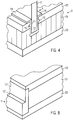
- FIG. 4 shows a perspective view of a profiled strip 1 for a lightweight board according to the first embodiment of the invention in the assembled state in a lightweight board 2.
- a lever element acting on the element 3, which acts on the profiled strip 1, is transmitted via the flange portions 14 on the upper cover layer 22 of the lightweight board 2.
- the equipped with the profile strip 1 according to the invention lightweight board 2 comes in a preferred manner in cabinet furniture used.
- the lightweight board 2 preferably forms a side wall part of the cabinet furniture, and the profiled strip 1 serves to connect a transverse to the side wall part to be arranged rear wall of the cabinet furniture.
- the profile strip 1 is designed for a lightweight board according to the first embodiment of the invention as a guide rail for guiding a relative to the lightweight board 2 movable shutter.
- the lightweight board 2 is formed as a side wall part of a cabinet furniture, wherein the profiled strip 1 is arranged on a loading opening defining front of the cabinet furniture to extend laterally along the feed opening of the cabinet furniture in a vertical direction, so that a shutter in a vertical direction in formed as a guide rail profile strip 1 can be performed according to the first embodiment, so that the shutter movable and an opening is closable.
- a second lightweight panel 2 is arranged with the trained as a guide rail profile strip 1 according to the first embodiment of the invention mirror symmetry to the first lightweight panel 2, so that the individual shutter elements can be performed at both ends of the guide rails (eg, spring-groove principle) ,
- a lightweight panel 2 according to the invention with the profiled strip 1 according to the first embodiment of the invention respectively forms the upper part and / or lower part of a cabinet cabinet.
- the lightweight board 2 is formed as a top and / or bottom of a cupboard furniture, wherein the profiled strip 1 is disposed on a loading opening defining top and / or bottom of the cabinet furniture to extend in a horizontal direction laterally along the loading opening of the cabinet furniture, so that a roller shutter or a sliding door can be guided in a horizontal direction in the profile rail 1 formed as a guide rail according to the first embodiment.
- a second lightweight panel 2 is arranged with the profile rail 1 formed as a guide rail according to the first embodiment of the invention mirror-symmetrical to the first lightweight panel 2, so that the Roller shutter or the sliding door at both ends at the ends in the guide rails (eg, spring-groove principle) can be performed.
- the Roller shutter or the sliding door at both ends at the ends in the guide rails eg, spring-groove principle
- FIG. 5 shows a sectional view of a profile strip 1 'for a lightweight panel according to the second embodiment of the invention.
- the profiled strip 1 'according to the second embodiment is extruded with the illustrated cross-section, so that it has a substantially L-shaped structure with two legs in cross-section, wherein the support sections 11', 12 'at different legs of the profiled strip 1' are formed.
- the profiled strip 1 ' comprises two mutually integrally formed, substantially parallelepiped-shaped sections 13', 14 'with different widths.
- the first support portion 11 ' is formed on a side surface of the cuboidal portion of lesser width 13', the second support portion 12 'being formed on an end face of the wider parallelepiped portion 14' projecting above the first support portion 11 '.
- the support sections 11 'and 12' form contact surfaces, which form essentially a right angle.
- One of the lightweight panel adjacent to be arranged element 3 is simultaneously on the two support sections 11 'and 12' in abutment and in two different support directions R 1 , R 2 can be supported.
- FIG. 6 shows the profiled strip 1 'for a lightweight panel according to the second embodiment of the invention, wherein the profiled strip 1' is associated with a decorative strip 5 '.
- the decorative strip 5 ' is attached or glued to a side wall of the cuboid portion of greater width 14'.
- Between the first support portion 11 'of the profile strip 1' and the decorative strip 5 ' is a pocket for receiving a lightweight panel 2 to be arranged adjacent element 3' defined.
- the decorative strip 5 ' is preferably made of plastic and provided with a decor or a coloring.
- FIG. 7 shows a sectional view of the profile strip 1 'for a lightweight panel according to the second embodiment of the invention in the assembled state in conjunction with one of the lightweight panel 2 adjacent to be arranged element 3', wherein the element 3 'in two different support directions R 1 , R 2 to the first and second support portions 11 'and 12' is supported.
- the profiled strip 1 ' is arranged on the end face of the lightweight board 2 in order to close the core 21 of the lightweight board 2 exposing opening on the front side of the lightweight board 2 moisture-tight.
- a groove projecting into the core 21 and into both cover layers 22 is milled into the end face of the lightweight board 2 on the end face of the lightweight board in a preferred manner.
- the profile bar 1 ' according to the second embodiment of the invention is arranged in this groove such that the profiled strip 1' is bordered by the outer layers 22, and the surfaces exposed to the outside of the profile strip 1 'flush with the end faces of the cover layers 22.
- the width of the second support portion 12 ' is matched to the width of the member 3' to be arranged adjacent to the lightweight panel 2, so that the member 3 'can be arranged to engage the first and second support portions 11' and 12 'in two different support directions R 1 , R 2 , so that the outer side of the element 3 'is flush with the exposed to the outside side of the profile strip 1'.
- this joint at which the cover layer 22, the side of the profile strip 1 'exposed to the outside and the side of the element 3' which is exposed to the outside flush with one another, is covered with a decorative strip 5 ', as clearly shown in FIG FIG. 7 is shown to hide the joint.
- FIG. 8 shows a perspective view of the profile strip 1 'for a lightweight panel according to the second embodiment of the invention in the assembled state in conjunction with the lightweight panel 2.
- the profiled strip 1' is incorporated into the lightweight panel 2, that the profiled strip 1 'arranged on the front side of the lightweight panel 2 is and the profile strip 1 'is flush with the end faces of the cover layers 22.
Landscapes
- Engineering & Computer Science (AREA)
- Architecture (AREA)
- Civil Engineering (AREA)
- Structural Engineering (AREA)
- Life Sciences & Earth Sciences (AREA)
- Wood Science & Technology (AREA)
- Physics & Mathematics (AREA)
- Electromagnetism (AREA)
- Securing Of Glass Panes Or The Like (AREA)
- Panels For Use In Building Construction (AREA)
Claims (10)
- Panneau de construction léger (2) doté d'une baguette profilée (1), le panneau de construction léger (2) présentant un coeur (21) et deux couches de recouvrement (22) recouvrant au moins en partie le coeur (21), le coeur (21) se composant d'un matériau contenant de la cellulose et les couches de recouvrement (22) se composant de bois, la baguette profilée (1) étant réalisée en plastique, la baguette profilée (1) pouvant être disposée de manière à s'étendre dans l'état monté au moins en partie entre les couches de recouvrement (22) du panneau de construction léger (2), la baguette profilée (1) présentant deux portions de support (11, 12), afin de supporter dans deux directions (R1, R2) un élément (3) devant être disposé à côté du panneau de construction léger (2), caractérisé en ce que la baguette profilée (1) est disposée dans une rainure qui traverse une couche de recouvrement (22) du panneau de construction léger (2), en ce que la baguette profilée (1) ferme de manière étanche à l'humidité une ouverture dans le panneau de construction léger (2) exposant le coeur (21) du panneau de construction léger (2), la baguette profilée (1) présentant une portion de réception (13) pour recevoir une portion de bord de l'élément (3) devant être disposé à côté du panneau de construction léger (2), la portion de réception (13) étant réalisée essentiellement en forme de U en section transversale et définissant une rainure.
- Panneau de construction léger (2) selon la revendication 1, dans lequel les deux portions de support (11, 12) sont réalisées de manière à supporter l'élément (3) devant être disposé à côté du panneau de construction léger (2) dans deux directions (R1, R2) qui s'étendent essentiellement perpendiculairement l'une à l'autre.
- Panneau de construction léger (2) selon l'une quelconque des revendications précédentes, dans lequel la baguette profilée (1) présente au moins une portion de bride (14) disposée latéralement par rapport à la portion de réception (13), laquelle s'étend transversalement à la direction longitudinale de la baguette profilée (1).
- Panneau de construction léger (2) selon l'une quelconque des revendications précédentes, dans lequel la baguette profilée (1) présente au moins une portion de bride (14) de chaque côté de la portion de réception (13).
- Panneau de construction léger (2) selon l'une quelconque des revendications précédentes, dans lequel la portion de bride (14) présente une portion d'appui pouvant être appliquée contre une surface d'une couche de recouvrement (22).
- Panneau de construction léger (2) selon l'une quelconque des revendications précédentes, dans lequel la baguette profilée (1) présente un moyen de fixation (15) par lequel la baguette profilée (1) peut être fixée par engagement par correspondance de formes au panneau de construction léger (2).
- Panneau de construction léger (2) selon l'une quelconque des revendications précédentes, dans lequel le moyen de fixation (15) comprend au moins une nervure de retenue s'étendant dans la direction longitudinale de la baguette profilée (1).
- Panneau de construction léger (2) selon l'une quelconque des revendications précédentes, dans lequel la portion de réception (13) présente deux parois latérales espacées l'une de l'autre et un fond reliant les parois latérales, la première portion de support (11) étant réalisée au niveau de l'une des parois latérales de la portion de réception (13) et la deuxième portion de support (12) étant réalisée au niveau du fond de la portion de réception (13).
- Panneau de construction léger (2) selon l'une quelconque des revendications précédentes, dans lequel la baguette profilée (1) est réalisée essentiellement en forme de L en section transversale et comprend deux branches, les portions de support (11, 12) étant réalisées au niveau de branches différentes de la baguette profilée (1).
- Panneau de construction léger (2) selon l'une quelconque des revendications précédentes, dans lequel la baguette profilée (1) présente un profilé creux de section transversale essentiellement fermée, qui peut être ouvert pour introduire l'élément (3) devant être disposé à côté du panneau de construction léger (2).
Priority Applications (1)
| Application Number | Priority Date | Filing Date | Title |
|---|---|---|---|
| PL08008408T PL1990477T3 (pl) | 2007-05-08 | 2008-05-05 | Lekka płyta budowlana z listwą profilową |
Applications Claiming Priority (1)
| Application Number | Priority Date | Filing Date | Title |
|---|---|---|---|
| DE202007006779U DE202007006779U1 (de) | 2007-05-08 | 2007-05-08 | Profilleiste für eine Leichtbauplatte und Leichtbauplatte mit einer Profilleiste |
Publications (3)
| Publication Number | Publication Date |
|---|---|
| EP1990477A2 EP1990477A2 (fr) | 2008-11-12 |
| EP1990477A3 EP1990477A3 (fr) | 2011-03-09 |
| EP1990477B1 true EP1990477B1 (fr) | 2017-06-21 |
Family
ID=39711087
Family Applications (1)
| Application Number | Title | Priority Date | Filing Date |
|---|---|---|---|
| EP08008408.0A Active EP1990477B1 (fr) | 2007-05-08 | 2008-05-05 | Panneau de construction léger doté d'une baguette de profilé |
Country Status (3)
| Country | Link |
|---|---|
| EP (1) | EP1990477B1 (fr) |
| DE (1) | DE202007006779U1 (fr) |
| PL (1) | PL1990477T3 (fr) |
Families Citing this family (1)
| Publication number | Priority date | Publication date | Assignee | Title |
|---|---|---|---|---|
| DE102009011729A1 (de) | 2009-03-09 | 2010-09-23 | Fritz Egger Gmbh & Co. | Leichtbauplatte für den Möbelbau |
Family Cites Families (9)
| Publication number | Priority date | Publication date | Assignee | Title |
|---|---|---|---|---|
| GB959983A (en) * | 1960-03-22 | 1964-06-03 | Herbert Ender | Improvements in protective facing arrangements |
| US3319384A (en) * | 1964-09-08 | 1967-05-16 | Edward T Berg | Construction for extruded reglets |
| GB1480743A (en) * | 1973-10-31 | 1977-07-20 | Rolls Royce | Metal cellular sandwich structures |
| CA2209664C (fr) * | 1995-01-06 | 2005-06-07 | The Burke Group | Structure en beton ayant un element d'insertion pour transferer des charges et procede de realisation |
| DE19506158A1 (de) | 1995-02-22 | 1996-08-29 | Oeco Team Unternehmens Und Umw | Halte- und Abschlußprofil |
| AU2262399A (en) * | 1998-02-19 | 1999-09-06 | Jenny & Co. Ag | Set of construction members for realising a construction body and method for producing and using the same |
| DE20003679U1 (de) * | 2000-02-29 | 2000-08-17 | Trw Automotive Electron & Comp | Bauteil |
| WO2004033809A2 (fr) * | 2002-10-11 | 2004-04-22 | Douglas Robert B | Structure modulaire permettant de construire des panneaux et leurs procedes de production et d'utilisation |
| DE202006003857U1 (de) | 2006-03-11 | 2006-07-13 | W. Döllken & Co. GmbH | Stützleiste für eine Verbundplatte |
-
2007
- 2007-05-08 DE DE202007006779U patent/DE202007006779U1/de not_active Expired - Lifetime
-
2008
- 2008-05-05 EP EP08008408.0A patent/EP1990477B1/fr active Active
- 2008-05-05 PL PL08008408T patent/PL1990477T3/pl unknown
Also Published As
| Publication number | Publication date |
|---|---|
| EP1990477A2 (fr) | 2008-11-12 |
| EP1990477A3 (fr) | 2011-03-09 |
| DE202007006779U1 (de) | 2008-09-25 |
| PL1990477T3 (pl) | 2017-11-30 |
Similar Documents
| Publication | Publication Date | Title |
|---|---|---|
| EP0200760B1 (fr) | Barre profilee pour le serrage des plaques, surtout les plaques en verre, pour des vitrines, distributeurs de vente, mobilier d'exposition et objets semblables | |
| EP2063047B1 (fr) | Système de rails profilés | |
| DE602004011838T2 (de) | Verfahren zur herstellung einer bodenplatte | |
| EP1710363B1 (fr) | Système de mur avec panneaux de verre | |
| DE2518365B2 (de) | Bilderrahmen | |
| DE102009047415A1 (de) | Anordnung mit Platten, insbesondere Gipskarton- und/oder Gipsfaserplatten für den Trockenbau, und mit einem Montagehilfselement sowie Montageverfahren hiermit | |
| WO2008092699A1 (fr) | Dispositif d'inspection, en particulier élément de recouvrement d'inspection | |
| EP1990477B1 (fr) | Panneau de construction léger doté d'une baguette de profilé | |
| EP2806094B1 (fr) | Vantail pour un agencement de porte | |
| DE102007007620A1 (de) | Wand- oder Deckenverkleidung | |
| DE3939872C2 (de) | Befestigungsvorrichtung | |
| EP2105065A1 (fr) | Corps de meuble | |
| EP2105063A1 (fr) | Corps de meuble | |
| WO2009006926A1 (fr) | CONCEPT DE PANNEAU DE PAROI À 45º | |
| DE19908393C2 (de) | Fassadenplatte | |
| DE4141288A1 (de) | Abschlussleiste fuer eine wand oder eine decke | |
| WO2012020093A2 (fr) | Élément de fixation pour la fixation de panneaux sur ununtergrund et combinaison d'un rail profilé abschlussprofilschiene doté d'un élément de retenue | |
| DE4042660C2 (de) | Sprossenkreuzkonstruktion | |
| EP2486825B1 (fr) | Agencement de fixation | |
| EP3450649A1 (fr) | Profilé de fixation | |
| EP2586928B1 (fr) | Support de plaque en particulier pour panneaux en verre | |
| EP2505760A2 (fr) | Module de réception d'une porte coulissante, dispositif de porte coulissante et procédé de montage d'un dispositif de porte coulissante | |
| DE102007006401B4 (de) | Reinraumwand | |
| DE102005032063B3 (de) | Beschlag zur Klemmbefestigung einer Glasscheibe | |
| EP0835979B1 (fr) | Volet roulant et son cache intérieure |
Legal Events
| Date | Code | Title | Description |
|---|---|---|---|
| PUAI | Public reference made under article 153(3) epc to a published international application that has entered the european phase |
Free format text: ORIGINAL CODE: 0009012 |
|
| AK | Designated contracting states |
Kind code of ref document: A2 Designated state(s): AT BE BG CH CY CZ DE DK EE ES FI FR GB GR HR HU IE IS IT LI LT LU LV MC MT NL NO PL PT RO SE SI SK TR |
|
| AX | Request for extension of the european patent |
Extension state: AL BA MK RS |
|
| PUAL | Search report despatched |
Free format text: ORIGINAL CODE: 0009013 |
|
| AK | Designated contracting states |
Kind code of ref document: A3 Designated state(s): AT BE BG CH CY CZ DE DK EE ES FI FR GB GR HR HU IE IS IT LI LT LU LV MC MT NL NO PL PT RO SE SI SK TR |
|
| AX | Request for extension of the european patent |
Extension state: AL BA MK RS |
|
| RIC1 | Information provided on ipc code assigned before grant |
Ipc: E04C 2/36 20060101AFI20080901BHEP Ipc: E04B 1/41 20060101ALI20110203BHEP |
|
| 17P | Request for examination filed |
Effective date: 20110718 |
|
| AKX | Designation fees paid |
Designated state(s): AT BE BG CH CY CZ DE DK EE ES FI FR GB GR HR HU IE IS IT LI LT LU LV MC MT NL NO PL PT RO SE SI SK TR |
|
| 17Q | First examination report despatched |
Effective date: 20130426 |
|
| GRAP | Despatch of communication of intention to grant a patent |
Free format text: ORIGINAL CODE: EPIDOSNIGR1 |
|
| INTG | Intention to grant announced |
Effective date: 20170102 |
|
| GRAS | Grant fee paid |
Free format text: ORIGINAL CODE: EPIDOSNIGR3 |
|
| GRAA | (expected) grant |
Free format text: ORIGINAL CODE: 0009210 |
|
| AK | Designated contracting states |
Kind code of ref document: B1 Designated state(s): AT BE BG CH CY CZ DE DK EE ES FI FR GB GR HR HU IE IS IT LI LT LU LV MC MT NL NO PL PT RO SE SI SK TR |
|
| REG | Reference to a national code |
Ref country code: GB Ref legal event code: FG4D Free format text: NOT ENGLISH |
|
| REG | Reference to a national code |
Ref country code: CH Ref legal event code: EP |
|
| REG | Reference to a national code |
Ref country code: IE Ref legal event code: FG4D Free format text: LANGUAGE OF EP DOCUMENT: GERMAN |
|
| REG | Reference to a national code |
Ref country code: AT Ref legal event code: REF Ref document number: 903073 Country of ref document: AT Kind code of ref document: T Effective date: 20170715 |
|
| REG | Reference to a national code |
Ref country code: DE Ref legal event code: R096 Ref document number: 502008015401 Country of ref document: DE |
|
| REG | Reference to a national code |
Ref country code: SE Ref legal event code: TRGR |
|
| REG | Reference to a national code |
Ref country code: NL Ref legal event code: MP Effective date: 20170621 |
|
| PG25 | Lapsed in a contracting state [announced via postgrant information from national office to epo] |
Ref country code: LT Free format text: LAPSE BECAUSE OF FAILURE TO SUBMIT A TRANSLATION OF THE DESCRIPTION OR TO PAY THE FEE WITHIN THE PRESCRIBED TIME-LIMIT Effective date: 20170621 Ref country code: FI Free format text: LAPSE BECAUSE OF FAILURE TO SUBMIT A TRANSLATION OF THE DESCRIPTION OR TO PAY THE FEE WITHIN THE PRESCRIBED TIME-LIMIT Effective date: 20170621 Ref country code: HR Free format text: LAPSE BECAUSE OF FAILURE TO SUBMIT A TRANSLATION OF THE DESCRIPTION OR TO PAY THE FEE WITHIN THE PRESCRIBED TIME-LIMIT Effective date: 20170621 Ref country code: GR Free format text: LAPSE BECAUSE OF FAILURE TO SUBMIT A TRANSLATION OF THE DESCRIPTION OR TO PAY THE FEE WITHIN THE PRESCRIBED TIME-LIMIT Effective date: 20170922 Ref country code: NO Free format text: LAPSE BECAUSE OF FAILURE TO SUBMIT A TRANSLATION OF THE DESCRIPTION OR TO PAY THE FEE WITHIN THE PRESCRIBED TIME-LIMIT Effective date: 20170921 |
|
| REG | Reference to a national code |
Ref country code: LT Ref legal event code: MG4D |
|
| PG25 | Lapsed in a contracting state [announced via postgrant information from national office to epo] |
Ref country code: BG Free format text: LAPSE BECAUSE OF FAILURE TO SUBMIT A TRANSLATION OF THE DESCRIPTION OR TO PAY THE FEE WITHIN THE PRESCRIBED TIME-LIMIT Effective date: 20170921 Ref country code: NL Free format text: LAPSE BECAUSE OF FAILURE TO SUBMIT A TRANSLATION OF THE DESCRIPTION OR TO PAY THE FEE WITHIN THE PRESCRIBED TIME-LIMIT Effective date: 20170621 Ref country code: LV Free format text: LAPSE BECAUSE OF FAILURE TO SUBMIT A TRANSLATION OF THE DESCRIPTION OR TO PAY THE FEE WITHIN THE PRESCRIBED TIME-LIMIT Effective date: 20170621 |
|
| PG25 | Lapsed in a contracting state [announced via postgrant information from national office to epo] |
Ref country code: SK Free format text: LAPSE BECAUSE OF FAILURE TO SUBMIT A TRANSLATION OF THE DESCRIPTION OR TO PAY THE FEE WITHIN THE PRESCRIBED TIME-LIMIT Effective date: 20170621 Ref country code: RO Free format text: LAPSE BECAUSE OF FAILURE TO SUBMIT A TRANSLATION OF THE DESCRIPTION OR TO PAY THE FEE WITHIN THE PRESCRIBED TIME-LIMIT Effective date: 20170621 Ref country code: EE Free format text: LAPSE BECAUSE OF FAILURE TO SUBMIT A TRANSLATION OF THE DESCRIPTION OR TO PAY THE FEE WITHIN THE PRESCRIBED TIME-LIMIT Effective date: 20170621 Ref country code: CZ Free format text: LAPSE BECAUSE OF FAILURE TO SUBMIT A TRANSLATION OF THE DESCRIPTION OR TO PAY THE FEE WITHIN THE PRESCRIBED TIME-LIMIT Effective date: 20170621 |
|
| PG25 | Lapsed in a contracting state [announced via postgrant information from national office to epo] |
Ref country code: IT Free format text: LAPSE BECAUSE OF FAILURE TO SUBMIT A TRANSLATION OF THE DESCRIPTION OR TO PAY THE FEE WITHIN THE PRESCRIBED TIME-LIMIT Effective date: 20170621 Ref country code: IS Free format text: LAPSE BECAUSE OF FAILURE TO SUBMIT A TRANSLATION OF THE DESCRIPTION OR TO PAY THE FEE WITHIN THE PRESCRIBED TIME-LIMIT Effective date: 20171021 Ref country code: ES Free format text: LAPSE BECAUSE OF FAILURE TO SUBMIT A TRANSLATION OF THE DESCRIPTION OR TO PAY THE FEE WITHIN THE PRESCRIBED TIME-LIMIT Effective date: 20170621 |
|
| REG | Reference to a national code |
Ref country code: DE Ref legal event code: R097 Ref document number: 502008015401 Country of ref document: DE |
|
| PLBE | No opposition filed within time limit |
Free format text: ORIGINAL CODE: 0009261 |
|
| STAA | Information on the status of an ep patent application or granted ep patent |
Free format text: STATUS: NO OPPOSITION FILED WITHIN TIME LIMIT |
|
| PG25 | Lapsed in a contracting state [announced via postgrant information from national office to epo] |
Ref country code: DK Free format text: LAPSE BECAUSE OF FAILURE TO SUBMIT A TRANSLATION OF THE DESCRIPTION OR TO PAY THE FEE WITHIN THE PRESCRIBED TIME-LIMIT Effective date: 20170621 |
|
| 26N | No opposition filed |
Effective date: 20180322 |
|
| PG25 | Lapsed in a contracting state [announced via postgrant information from national office to epo] |
Ref country code: SI Free format text: LAPSE BECAUSE OF FAILURE TO SUBMIT A TRANSLATION OF THE DESCRIPTION OR TO PAY THE FEE WITHIN THE PRESCRIBED TIME-LIMIT Effective date: 20170621 |
|
| PG25 | Lapsed in a contracting state [announced via postgrant information from national office to epo] |
Ref country code: MT Free format text: LAPSE BECAUSE OF FAILURE TO SUBMIT A TRANSLATION OF THE DESCRIPTION OR TO PAY THE FEE WITHIN THE PRESCRIBED TIME-LIMIT Effective date: 20170621 |
|
| REG | Reference to a national code |
Ref country code: CH Ref legal event code: PL |
|
| REG | Reference to a national code |
Ref country code: SE Ref legal event code: EUG |
|
| GBPC | Gb: european patent ceased through non-payment of renewal fee |
Effective date: 20180505 |
|
| REG | Reference to a national code |
Ref country code: BE Ref legal event code: MM Effective date: 20180531 |
|
| PG25 | Lapsed in a contracting state [announced via postgrant information from national office to epo] |
Ref country code: MC Free format text: LAPSE BECAUSE OF FAILURE TO SUBMIT A TRANSLATION OF THE DESCRIPTION OR TO PAY THE FEE WITHIN THE PRESCRIBED TIME-LIMIT Effective date: 20170621 Ref country code: SE Free format text: LAPSE BECAUSE OF NON-PAYMENT OF DUE FEES Effective date: 20180506 |
|
| REG | Reference to a national code |
Ref country code: IE Ref legal event code: MM4A |
|
| PG25 | Lapsed in a contracting state [announced via postgrant information from national office to epo] |
Ref country code: LI Free format text: LAPSE BECAUSE OF NON-PAYMENT OF DUE FEES Effective date: 20180531 Ref country code: CH Free format text: LAPSE BECAUSE OF NON-PAYMENT OF DUE FEES Effective date: 20180531 |
|
| PG25 | Lapsed in a contracting state [announced via postgrant information from national office to epo] |
Ref country code: LU Free format text: LAPSE BECAUSE OF NON-PAYMENT OF DUE FEES Effective date: 20180505 |
|
| PG25 | Lapsed in a contracting state [announced via postgrant information from national office to epo] |
Ref country code: GB Free format text: LAPSE BECAUSE OF NON-PAYMENT OF DUE FEES Effective date: 20180505 Ref country code: FR Free format text: LAPSE BECAUSE OF NON-PAYMENT OF DUE FEES Effective date: 20180531 Ref country code: IE Free format text: LAPSE BECAUSE OF NON-PAYMENT OF DUE FEES Effective date: 20180505 |
|
| PG25 | Lapsed in a contracting state [announced via postgrant information from national office to epo] |
Ref country code: BE Free format text: LAPSE BECAUSE OF NON-PAYMENT OF DUE FEES Effective date: 20180531 |
|
| REG | Reference to a national code |
Ref country code: AT Ref legal event code: MM01 Ref document number: 903073 Country of ref document: AT Kind code of ref document: T Effective date: 20180505 |
|
| PG25 | Lapsed in a contracting state [announced via postgrant information from national office to epo] |
Ref country code: AT Free format text: LAPSE BECAUSE OF NON-PAYMENT OF DUE FEES Effective date: 20180505 |
|
| PG25 | Lapsed in a contracting state [announced via postgrant information from national office to epo] |
Ref country code: PL Free format text: LAPSE BECAUSE OF NON-PAYMENT OF DUE FEES Effective date: 20180505 |
|
| PG25 | Lapsed in a contracting state [announced via postgrant information from national office to epo] |
Ref country code: TR Free format text: LAPSE BECAUSE OF FAILURE TO SUBMIT A TRANSLATION OF THE DESCRIPTION OR TO PAY THE FEE WITHIN THE PRESCRIBED TIME-LIMIT Effective date: 20170621 |
|
| PG25 | Lapsed in a contracting state [announced via postgrant information from national office to epo] |
Ref country code: HU Free format text: LAPSE BECAUSE OF FAILURE TO SUBMIT A TRANSLATION OF THE DESCRIPTION OR TO PAY THE FEE WITHIN THE PRESCRIBED TIME-LIMIT; INVALID AB INITIO Effective date: 20080505 Ref country code: PT Free format text: LAPSE BECAUSE OF FAILURE TO SUBMIT A TRANSLATION OF THE DESCRIPTION OR TO PAY THE FEE WITHIN THE PRESCRIBED TIME-LIMIT Effective date: 20170621 |
|
| PG25 | Lapsed in a contracting state [announced via postgrant information from national office to epo] |
Ref country code: CY Free format text: LAPSE BECAUSE OF FAILURE TO SUBMIT A TRANSLATION OF THE DESCRIPTION OR TO PAY THE FEE WITHIN THE PRESCRIBED TIME-LIMIT Effective date: 20170621 |
|
| REG | Reference to a national code |
Ref country code: DE Ref legal event code: R081 Ref document number: 502008015401 Country of ref document: DE Owner name: REHAU INDUSTRIES SE & CO. KG, DE Free format text: FORMER OWNER: REHAU AG + CO, 95111 REHAU, DE |
|
| PGFP | Annual fee paid to national office [announced via postgrant information from national office to epo] |
Ref country code: DE Payment date: 20230531 Year of fee payment: 16 |