EP1989151B1 - Method enabling dual pressure control within fiber preform during fiber fabrication - Google Patents
Method enabling dual pressure control within fiber preform during fiber fabrication Download PDFInfo
- Publication number
- EP1989151B1 EP1989151B1 EP07751302A EP07751302A EP1989151B1 EP 1989151 B1 EP1989151 B1 EP 1989151B1 EP 07751302 A EP07751302 A EP 07751302A EP 07751302 A EP07751302 A EP 07751302A EP 1989151 B1 EP1989151 B1 EP 1989151B1
- Authority
- EP
- European Patent Office
- Prior art keywords
- preform
- holes
- slot
- tube
- pressure
- Prior art date
- Legal status (The legal status is an assumption and is not a legal conclusion. Google has not performed a legal analysis and makes no representation as to the accuracy of the status listed.)
- Ceased
Links
- 239000000835 fiber Substances 0.000 title claims description 33
- 238000000034 method Methods 0.000 title claims description 28
- 238000004519 manufacturing process Methods 0.000 title claims description 14
- 230000009977 dual effect Effects 0.000 title 1
- 239000013307 optical fiber Substances 0.000 claims description 30
- 239000004038 photonic crystal Substances 0.000 claims description 14
- 238000004891 communication Methods 0.000 claims description 9
- 238000010438 heat treatment Methods 0.000 claims description 3
- 230000002401 inhibitory effect Effects 0.000 claims 2
- 239000011521 glass Substances 0.000 description 11
- 238000005253 cladding Methods 0.000 description 9
- 239000007789 gas Substances 0.000 description 9
- XKRFYHLGVUSROY-UHFFFAOYSA-N Argon Chemical compound [Ar] XKRFYHLGVUSROY-UHFFFAOYSA-N 0.000 description 4
- IJGRMHOSHXDMSA-UHFFFAOYSA-N Atomic nitrogen Chemical compound N#N IJGRMHOSHXDMSA-UHFFFAOYSA-N 0.000 description 4
- OKTJSMMVPCPJKN-UHFFFAOYSA-N Carbon Chemical compound [C] OKTJSMMVPCPJKN-UHFFFAOYSA-N 0.000 description 4
- 229910002804 graphite Inorganic materials 0.000 description 4
- 239000010439 graphite Substances 0.000 description 4
- 239000000463 material Substances 0.000 description 4
- 230000008569 process Effects 0.000 description 4
- 230000000717 retained effect Effects 0.000 description 4
- 238000005520 cutting process Methods 0.000 description 3
- 239000001307 helium Substances 0.000 description 3
- 229910052734 helium Inorganic materials 0.000 description 3
- SWQJXJOGLNCZEY-UHFFFAOYSA-N helium atom Chemical compound [He] SWQJXJOGLNCZEY-UHFFFAOYSA-N 0.000 description 3
- 230000007246 mechanism Effects 0.000 description 3
- 238000003466 welding Methods 0.000 description 3
- 229910052786 argon Inorganic materials 0.000 description 2
- 230000005540 biological transmission Effects 0.000 description 2
- 230000008878 coupling Effects 0.000 description 2
- 238000010168 coupling process Methods 0.000 description 2
- 238000005859 coupling reaction Methods 0.000 description 2
- 230000007547 defect Effects 0.000 description 2
- 229910003460 diamond Inorganic materials 0.000 description 2
- 239000010432 diamond Substances 0.000 description 2
- 239000006185 dispersion Substances 0.000 description 2
- 239000011261 inert gas Substances 0.000 description 2
- 238000007537 lampworking Methods 0.000 description 2
- 229910052757 nitrogen Inorganic materials 0.000 description 2
- 230000003287 optical effect Effects 0.000 description 2
- 230000000737 periodic effect Effects 0.000 description 2
- 239000007787 solid Substances 0.000 description 2
- 239000004593 Epoxy Substances 0.000 description 1
- 238000010521 absorption reaction Methods 0.000 description 1
- QVGXLLKOCUKJST-UHFFFAOYSA-N atomic oxygen Chemical compound [O] QVGXLLKOCUKJST-UHFFFAOYSA-N 0.000 description 1
- 230000015572 biosynthetic process Effects 0.000 description 1
- 238000001816 cooling Methods 0.000 description 1
- 238000005553 drilling Methods 0.000 description 1
- 230000000694 effects Effects 0.000 description 1
- 238000005516 engineering process Methods 0.000 description 1
- 238000003698 laser cutting Methods 0.000 description 1
- 238000001459 lithography Methods 0.000 description 1
- 238000003754 machining Methods 0.000 description 1
- 239000000203 mixture Substances 0.000 description 1
- 238000012986 modification Methods 0.000 description 1
- 230000004048 modification Effects 0.000 description 1
- 239000001301 oxygen Substances 0.000 description 1
- 229910052760 oxygen Inorganic materials 0.000 description 1
- 239000012780 transparent material Substances 0.000 description 1
- XLYOFNOQVPJJNP-UHFFFAOYSA-N water Substances O XLYOFNOQVPJJNP-UHFFFAOYSA-N 0.000 description 1
Images


Classifications
-
- C—CHEMISTRY; METALLURGY
- C03—GLASS; MINERAL OR SLAG WOOL
- C03B—MANUFACTURE, SHAPING, OR SUPPLEMENTARY PROCESSES
- C03B37/00—Manufacture or treatment of flakes, fibres, or filaments from softened glass, minerals, or slags
- C03B37/01—Manufacture of glass fibres or filaments
- C03B37/02—Manufacture of glass fibres or filaments by drawing or extruding, e.g. direct drawing of molten glass from nozzles; Cooling fins therefor
- C03B37/025—Manufacture of glass fibres or filaments by drawing or extruding, e.g. direct drawing of molten glass from nozzles; Cooling fins therefor from reheated softened tubes, rods, fibres or filaments, e.g. drawing fibres from preforms
- C03B37/027—Fibres composed of different sorts of glass, e.g. glass optical fibres
- C03B37/02781—Hollow fibres, e.g. holey fibres
-
- C—CHEMISTRY; METALLURGY
- C03—GLASS; MINERAL OR SLAG WOOL
- C03B—MANUFACTURE, SHAPING, OR SUPPLEMENTARY PROCESSES
- C03B37/00—Manufacture or treatment of flakes, fibres, or filaments from softened glass, minerals, or slags
- C03B37/07—Controlling or regulating
-
- C—CHEMISTRY; METALLURGY
- C03—GLASS; MINERAL OR SLAG WOOL
- C03B—MANUFACTURE, SHAPING, OR SUPPLEMENTARY PROCESSES
- C03B37/00—Manufacture or treatment of flakes, fibres, or filaments from softened glass, minerals, or slags
- C03B37/01—Manufacture of glass fibres or filaments
- C03B37/02—Manufacture of glass fibres or filaments by drawing or extruding, e.g. direct drawing of molten glass from nozzles; Cooling fins therefor
- C03B37/022—Manufacture of glass fibres or filaments by drawing or extruding, e.g. direct drawing of molten glass from nozzles; Cooling fins therefor from molten glass in which the resultant product consists of different sorts of glass or is characterised by shape, e.g. hollow fibres, undulated fibres, fibres presenting a rough surface
-
- C—CHEMISTRY; METALLURGY
- C03—GLASS; MINERAL OR SLAG WOOL
- C03B—MANUFACTURE, SHAPING, OR SUPPLEMENTARY PROCESSES
- C03B37/00—Manufacture or treatment of flakes, fibres, or filaments from softened glass, minerals, or slags
- C03B37/10—Non-chemical treatment
- C03B37/14—Re-forming fibres or filaments, i.e. changing their shape
- C03B37/15—Re-forming fibres or filaments, i.e. changing their shape with heat application, e.g. for making optical fibres
-
- C—CHEMISTRY; METALLURGY
- C03—GLASS; MINERAL OR SLAG WOOL
- C03B—MANUFACTURE, SHAPING, OR SUPPLEMENTARY PROCESSES
- C03B2203/00—Fibre product details, e.g. structure, shape
- C03B2203/42—Photonic crystal fibres, e.g. fibres using the photonic bandgap PBG effect, microstructured or holey optical fibres
-
- C—CHEMISTRY; METALLURGY
- C03—GLASS; MINERAL OR SLAG WOOL
- C03B—MANUFACTURE, SHAPING, OR SUPPLEMENTARY PROCESSES
- C03B2205/00—Fibre drawing or extruding details
- C03B2205/10—Fibre drawing or extruding details pressurised
Definitions
- the invention is directed to a method of fabricating a photonic crystal optical fiber or photonic band gap fiber, and in particular to a method providing independent control of pressures within a plurality of longitudinally-extending holes within a preform during the draw of the preform into the optical fiber.
- Optic fibers are used in a wide variety of fields, including telecommunications, laser machining and welding, laser beam and power delivery, fiber lasers, etc.
- fibers are constructed from solid transparent materials such as glass and have a similar cross-sectional configuration along the length thereof.
- An alternative design to such fibers includes a microstructured optical fiber having holes or voids running longitudinally along the fiber axis. These holes generally contain air or an inert gas, but may also contain other materials.
- Microstructured optical fibers may be designed to optimize a wide variety of properties, and are useful in numerous applications.
- microstructured optical fibers may include solid glass core and a plurality of holes disposed in a cladding region around the core in a manner wherein the position and sizes of the holes are designed to yield dispersion values ranging between large negative values and large positive values. These particular fibers are useful in applications requiring dispersion compensation.
- Solid-core microstructured optical fibers may also be designed to provide a single mode wave guidance over a wide range of wavelengths. The majority of solid-core microstructured optical fibers guide light by a total internal reflection mechanism, wherein a low index of the associated holes act to lower the index of the cladding region in which they are disposed.
- Photonic band gap fibers that guide light by a mechanism that is fundamentally different from the total internal reflection mechanism.
- Photonic band gap fibers have a photonic crystal structure formed in the cladding of the fiber, wherein the photonic crystal structure comprises a periodic array of holes.
- a core of the fiber is formed by a defect in the photonic crystal structure cladding.
- the defect may include a hole of a substantially different size and/or shape than the holes of the photonic crystal structure.
- photonic band gap fibers are constructed with a hollow air core surrounded by a cladding structure that consists of a periodic array of air holes within the glass.
- the photonic crystal structure of the microstructured optical fibers has a range of frequencies, known as the band gap, within which light cannot propagate within the photonic crystal structure.
- the band gap In application, light introduced into the core of the fiber having a frequency within the band gap will not propagate in the photonic crystal cladding, and will therefore be confined within the core.
- a photonic band gap fiber may have a core that is formed from a hole larger than those of the photonic crystal structure.
- the key aspect of the hollow core photonic band gap technology is the production of a fiber with an air core having a low non-linearity and low attenuation. Specifically, the light is guided within a gaseous medium, lowering the losses due to absorption and rayleigh scattering associated with the glass materials.
- the hollow-core fiber may be constructed to provide extremely low non-linearity.
- hollow-core microstructured optical fibers are well-suited for guiding light over a very broad range of wavelengths. Advantages of such a fiber include the application within high power transmission at wavelengths of from UV to IR range, such as within welding, lithography, cutting industries, and the like, and also for applications requiring ultra-low loss transmission of telecommunication signals.
- Microstructured optical fibers are fabricated using methods roughly analogous to the manufacture of all-glass optical fibers.
- a preform having the desired arrangement of holes is formed, then drawn into fiber using heat and tension.
- the size, shape and arrangement of the holes may be significantly distorted depending on the viscosity of the material and surface tension within the holes.
- Such distortions are especially damaging in hollow-core photonic band gap fibers, as the band gap may be quite sensitive to variations in characteristic dimensions of the photonic crystal structure such as hole size, pitch and symmetry.
- Such distortions can also affect the geometry of the core/cladding boundary which can in turn have a significant effect on the attenuation behavior of the guided mode.
- the manufacturing process utilized to manufacture hollow-core microstructured optical fibers have been difficult to reproduce, relatively expensive, and time consuming.
- the holes of the preform used to make microstructured optical fibers can be quite small (e.g. less than a few hundred microns in diameter), and coupling the numerous holes of the microstructured optical fiber preform to different pressure systems is not a trivial task.
- a method is desired that enables improved control of the fiber geometry and yet is still practical, robust and repeatable, thereby reducing the overall time, cost and complexity associated with the manufacture of hollow-core microstructured optical fibers.
- US 6,996,317 describes a microstructured optical component that is formed from a preform.
- the preform includes a set of internal optical elements.
- US2005/0238301 describes drawing an optical fiber from a preform with elongate holes, at least one but not all being connected to an external pressure controller for controlling gas pressure.
- W02005/012197 describes drawing an optical fiber from an elongate preform, and controlling the external gas pressure.
- W02003/0230118 describes drawing a microstructured fiber from a preform with a first set of holes and a second set of holes, the first set of holes being coupled to a pressure system.
- One aspect of the present invention relates to a method of fabricating a photonic crystal optical fiber, wherein the method comprises providing a preform that includes a plurality of holes and an outer diameter, the holes extending from a first end of the preform to a second end of the preform, and forming at least one radially inwardly-extending slot within the preform such that the at least one slot intersects at least some of the holes, wherein the slot does not intersect at least one hole.
- the method also comprises establishing a first pressure in the holes intersected by the at least one slot by introducing the first pressure to the at least one slot, and establishing a second pressure in the at least one hole not intersected by the at least one slot by introducing the second pressure to an end of the at least one hole not intersected by the at least one slot.
- the method further comprises drawing the preform into a fiber while independently controlling the first and second pressures.
- the present inventive methods disclosed herein allow practical, robust and repeatable solutions for manufacturing hollow-core microstructured optical fibers. These methods reduce the time, expense and complexity of the process normally associated with the manufacture of hollow-core microstructured optical fibers and are particularly well suited for the proposed use.
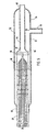
- Fig. 1 is a side view of a preform to be formed into a hollow-core microstructured optical fiber
- Fig. 2 is an end view of the preform
- Fig. 3 is a partially cross-sectional side view of the preform, wherein holes extending longitudinally through the preform have been closed at one end thereof, and wherein an alternative graphite rod is shown in dashed lines;
- Fig. 4A is a cross-sectional view of the preform taken along the line IVA-IVA, Fig. 3 ;
- Fig. 4B is a cross-sectional view of the preform taken along the line IVB-IVB, Fig. 3 ;
- Fig. 4C is a cross-sectional view of the preform taken along the line IVC-IVC, Fig. 3 ;
- Fig. 4D is a cross-sectional view of the preform taken along the line IVD-IVD, Fig. 3 ;
- Fig. 4E is a cross-sectional view of the preform taken along the line IVE-IVE, Fig. 3 ;
- Fig. 4F is a cross-sectional view of the preform taken along the line IVF-IVF, Fig. 3 ;
- Fig. 5 is a partially cross-sectional side view of the preform as coupled to first and second pressure tubes.
- a method for forming a microstructured optical fiber is provided.
- a preform having a plurality of holes and an outer diameter is provided, wherein the holes extend from a first end of the preform to a second end of the preform.
- a plurality of radially inwardly-extending slots are formed within the preform such that the slots intersect a number of the holes of the preform, and such that the slots do not intersect every one of the holes within the preform.
- a first pressure is then established within the holes intersected by the slots by introducing the first pressure to the slots, while a second pressure is established within the holes not intersected by the slots by introducing the second pressure to an end of those holes.
- the preform is then drawn into a fiber while the first and second pressures are independently controlled, thereby allowing the sizes, pitch, etc. of the holes to be controlled during the drawing of the fiber, as discussed in more detail below.
- the reference numeral 10 ( Fig. 1 ) generally designates an optical fiber preform for the production of a photonic crystal optical fiber.
- the preform 10 is constructed of a bundle of capillaries 12 each including a longitudinally-extending hole 14 ( Fig. 2 ).
- each of the holes 14 is hollow and includes a gaseous medium therein, however, it should be noted that at least some of the holes may include other refractive materials therein.
- the capillaries 12 are arranged in a manner so as to create a centrally-located, longitudinally-extending hollow core 16, the shape of which illustrates the difficulty in pneumatically coupling gas supply lines therewith.
- the plurality of holes 14 of the capillaries 12 forms an effective index cladding region for the core 16.
- a bundle of capillaries 12 is positioned within a large sleeve tube or glass jacket 18.
- the initial optical fiber preform 10 is formed by arranging a stack of glass tubes, at least some of which are capillaries 12 that include the holes 14, positioning the glass tubes within the large sleeve tube 18, and heating and redrawing (reducing the diameter of) the assembly to form the integral preform 10 with holes 14 still retained therein.
- the preform 10 defines a first end 22, a second end 20 and an outer diameter 23 with holes 14 still retained within the preform 10. It is noted that the relative size of the sleeve tube 18 with respect to the over size of the bundle of capillaries 12, and that the illustrated examples may not be shown to scale.
- a pressurized gas such as helium
- the pressurized gas is an inert gas such as helium, argon, or nitrogen, or a mixture thereof.
- the first end 22 of preform 10 is heated until the preform is sufficiently hot enough to close off the holes 14 within an end region 24 proximate the first end 22.
- the holes 14 are closed such that any air pressures supplied to the first end 22 of the preform 10 enter the core 16 but are prevented from entering the holes 14, as discussed below.
- a plug 28 such as for example, a graphite rod
- a plug 28 can be inserted into the hollow core 16 prior to the heating of the first end 22 of the preform 10, thereby preventing closure of the hollow core 16 when the end region 24 is heated and deformed so as to close the holes 14.
- a heated gas such as oxygen
- a sufficient amount of heat may also be externally applied to the end region 24 subsequent to the deformation and cooling of the same, thereby allowing removal of the graphite rod 28.
- a plurality of radially inwardly-extending slots 30 are formed within the preform 10.
- a total of six slots 32, 34, 36, 38, 40, 42 are formed.
- more or less slots could be employed as desired.
- Each slot 32, 34, 36, 38, 40, 42 intersect a number of the holes 14, thereby allowing pneumatic communication with the holes 14, as described below.
- a single slot may be formed so as to intersect 360° of the outer diameter 23 of the preform 10 and intersect with each and every hole 14 of the preform 10.
- at least two slots are formed in the preform 10 such that each of the slots intersects an arc of the outer diameter 23 of the preform 10 within the range of from about 30° to about 180°.
- multiple slots 30 are formed within the preform 10 each intersecting an arc of the outer diameter 23 within a range of from about 70° to about 180°.
- a total number of six slots 30 can be formed within the preform 10 each intersecting approximately 170°-180° of an arc of the outer diameter 23, however, other numbers of slots 30 may be utilized.
- the slots 32, 34, 36, 38, 40, 42 are each formed to intersect an arc ⁇ of the outer diameter 23 of between 170° and 180°.
- the preform 10 is rotated such that the second slot begins 120° from the beginning point of the first slot 32.
- This pattern is repeated such that the starting point of the third slot 36 is 120° rotated from the starting point of the second slot 34, the starting point of the fourth slot 38 is 180° rotated from the beginning point of the third slot 36, the beginning point of the fifth slot 40 is 120° rotated from the beginning of the fourth slot 38, and the beginning of the sixth slot 42 is 120° rotated from the beginning point of the fifth slot 40.
- the slots 30 of the instant example were formed via a diamond encrusted cutting wheel, however, other methods and devices suitable for such an application may be utilized, including diamond encrusted cutting wires, abrasive water jets, laser cutting, drilling, flame-working and the like.
- the slots 32, 34, 36, 38, 40, 42 are spaced from one another along the length of the preform 10 by a distance d, defined as the distance between the center line of each adjacent pair of slots 30.
- the distance d is within the range of from about 1 mm to about 5mm.
- each of the slots 32, 34, 36, 38, 40, 42 is within the range of from about 1m to about 4mm.
- the slots 32, 34, 36, 38, 40, and 42 in preform 10 may be fire polished subsequent to forming the slots therein to remove or reduce microcracks formed within the slots of preform 10 during formation thereof.
- a first glass tube 44 ( Fig. 5 ) is secured to the first end 22 of the preform 10.
- the first tube 44 includes a proximate end 46 that is flame-worked to the first end 22 of the preform 10, such that there is a gas tight seal therebetween.
- the first tube 44 is secured to the preform 10 such that the first tube 44 is in pneumatic communication with the hollow core 16.
- the distal end 48 of the first tube 44 is in pneumatic communication with a first pressure control system (not shown).
- a proximate end 50 of a second glass tube 52 is flame-worked to the outer diameter 23 of the preform 10, such that the second tube encapsulates at least a portion of the preform.
- the interior of the second tube 52 is in pneumatic communication with the slots 30.
- One end 50 of the second tube 52 is preferably flame-worked to the outer diameter 23 of the preform 10.
- a supply line 55 is flame-worked to an outer diameter 57 of the second tube 52 such that the supply line 55 is in pneumatic communication with the second tube 52 via an aperture 59 within the second tube 52.
- the supply line 55 is in pneumatic communication with a second pressure control system (not shown).
- the second tube 52 is configured such that a portion of the preform 10 and the first tube 44 is received therein.
- the first tube 44 can be slidably retained within distal end 54 of second tube 52.
- first tube 44 can be flame worked so that it is rigidly retained within distal end 54 of second tube 52.
- first tube 44 and the second tube 52 may be attached to the preform 10 by flame-working, other methods and processes suitable for such applications may also be utilized, such as a glass frit, laser welding, O-ring seals, epoxy, and the like.
- the preform 10 is drawn from the second end 20 thereof to reduce the diameter thereof and preferably form an optical fiber. If the preform 10 ( Fig. 3 ) is drawn into a fiber with a single pressure being applied to the holes 14 and the hollow core 16, substantial distortion of the microstructure may result. In particular, the hollow core 16 is distorted to be much larger in size relative to the holes 14 of the photonic crystal cladding. In some embodiments of the invention, i.e., those wherein the diameter of core 16 is greater than the diameter of the holes 14, a lower pressure than is employed within the holes 14 can be employed within the core 16 to maintain the relative size of the core 16 with respect to the holes 14. However, if the core diameter was smaller than the relative diameters of the holes 14, it is likely that one would want to utilize a greater pressure in the core 16 than in the holes 14.
- the first pressure control system may be set to a different pressure than the second pressure control system.
- the skilled artisan may set the pressure of the first pressure control system to be greater than the pressure of the second pressure control system in order to maintain the relative sizes of the hollow core 16 and the holes 14 relative to one another, thereby avoiding the distortion described above.
- the first pressure control system may be set to a substantially different pressure than the second pressure control system.
- the skilled artisan can control the pressures inside the cores 16 and the holes 14 to expand, maintain, or reduce the relative diameters of the holes during the draw.
- gases such as helium, argon, nitrogen and the like during the draw step
- the present inventive method allows the gases as inserted into the core 16 and the holes 14 to differ from one another.
- the first pressure i.e., that which is contact with holes 14
- the second pressure i.e., that which is in contact with the hollow core 16
- the first and second pressures may also be applied as a vacuum.
- Feedback control may be utilized to control the pressure of at least one the pressure control systems.
- the sizes of the holes may be monitored, and the size and information used as part of a feedback system to control relative pressures.
- a pressure monitor may be coupled to the hollow core 16 and/or the holes 14, and the pressure information therefrom used as part of a feedback system to control the relative pressure.
- the present inventive methods disclosed herein allow practical, robust and repeatable solutions for manufacturing hollow-core microstructured optical fibers. These methods reduce the time, expense and complexity of the process normally associated with the manufacture of hollow-core microstructured optical fibers and are particularly well suited for the proposed tasks.
Landscapes
- Engineering & Computer Science (AREA)
- Chemical & Material Sciences (AREA)
- Life Sciences & Earth Sciences (AREA)
- General Life Sciences & Earth Sciences (AREA)
- Geochemistry & Mineralogy (AREA)
- Manufacturing & Machinery (AREA)
- Materials Engineering (AREA)
- Organic Chemistry (AREA)
- Optical Fibers, Optical Fiber Cores, And Optical Fiber Bundles (AREA)
- Manufacture, Treatment Of Glass Fibers (AREA)
Applications Claiming Priority (2)
| Application Number | Priority Date | Filing Date | Title |
|---|---|---|---|
| US11/366,654 US7793521B2 (en) | 2006-03-01 | 2006-03-01 | Method enabling dual pressure control within fiber preform during fiber fabrication |
| PCT/US2007/004532 WO2007106305A2 (en) | 2006-03-01 | 2007-02-20 | Method enabling dual pressure control within fiber preform during fiber fabrication |
Publications (3)
| Publication Number | Publication Date |
|---|---|
| EP1989151A2 EP1989151A2 (en) | 2008-11-12 |
| EP1989151A4 EP1989151A4 (en) | 2011-07-06 |
| EP1989151B1 true EP1989151B1 (en) | 2012-11-07 |
Family
ID=38470313
Family Applications (1)
| Application Number | Title | Priority Date | Filing Date |
|---|---|---|---|
| EP07751302A Ceased EP1989151B1 (en) | 2006-03-01 | 2007-02-20 | Method enabling dual pressure control within fiber preform during fiber fabrication |
Country Status (6)
| Country | Link |
|---|---|
| US (1) | US7793521B2 (enExample) |
| EP (1) | EP1989151B1 (enExample) |
| JP (1) | JP5074427B2 (enExample) |
| KR (1) | KR20080113219A (enExample) |
| CN (1) | CN101426743A (enExample) |
| WO (1) | WO2007106305A2 (enExample) |
Families Citing this family (18)
| Publication number | Priority date | Publication date | Assignee | Title |
|---|---|---|---|---|
| US7343074B1 (en) * | 2007-02-27 | 2008-03-11 | Corning Incorporated | Optical waveguide environmental sensor and method of manufacture |
| US7496260B2 (en) * | 2007-03-27 | 2009-02-24 | Imra America, Inc. | Ultra high numerical aperture optical fibers |
| DE102007024725B4 (de) * | 2007-05-25 | 2011-09-29 | Heraeus Quarzglas Gmbh & Co. Kg | Abscheidebrenner und Verfahren für dessen Herstellung, dessen Verwendung in einer Brenneranordnung sowie Verfahren zur Herstellung eines Rohlings aus synthetischem Quarzglas unter Einsatz der Brenneranordnung |
| JP5170863B2 (ja) * | 2007-06-14 | 2013-03-27 | 古河電気工業株式会社 | ホーリーファイバの製造方法 |
| WO2009029987A1 (en) * | 2007-09-04 | 2009-03-12 | The University Of Sydney | A method for making microstructured fibres sensitive to the external environment |
| GB0719376D0 (en) * | 2007-10-03 | 2007-11-14 | Univ Bath | Hollow-core photonic crystal fibre |
| WO2010116762A1 (ja) * | 2009-04-09 | 2010-10-14 | 株式会社フジクラ | 空孔付き光ファイバの空孔径の測定方法および装置、ならびに空孔付き光ファイバの製造方法および装置 |
| CN102815864B (zh) * | 2012-09-21 | 2015-01-07 | 中国电子科技集团公司第四十六研究所 | 一种光子晶体光纤的制备方法 |
| EP3047319B8 (en) * | 2013-09-20 | 2021-06-30 | University Of Southampton | Methods of manufacturing hollow-core photonic bandgap fibers |
| WO2017080564A1 (en) | 2015-11-10 | 2017-05-18 | Nkt Photonics A/S | An element for a preform, a fiber production method and an optical fiber drawn from the preform |
| EP4009087B1 (en) | 2015-12-23 | 2024-11-06 | NKT Photonics A/S | Photonic crystal fiber assembly |
| EP3394650B1 (en) | 2015-12-23 | 2023-08-09 | NKT Photonics A/S | Hollow core optical fiber and a laser system |
| WO2017186246A1 (en) | 2016-04-27 | 2017-11-02 | Nkt Photonics A/S | A method of fiber production |
| RU2629133C1 (ru) * | 2016-09-27 | 2017-08-24 | Федеральное государственное бюджетное образовательное учреждение высшего образования "Саратовский национальный исследовательский государственный университет имени Н.Г. Чернышевского" | Способ селективной запайки внешних оболочек фотонно-кристаллических волноводов с полой сердцевиной |
| CN106495464B (zh) * | 2016-10-27 | 2018-10-16 | 北京航空航天大学 | 一种用于光子带隙光纤拉制的气压控制方法及装置 |
| US11787727B2 (en) * | 2018-04-18 | 2023-10-17 | Lawrence Livermore National Security, Llc | Method for fabrication of sleeveless photonic crystal canes with an arbitrary shape |
| US11203547B2 (en) * | 2018-07-23 | 2021-12-21 | Ofs Fitel, Llc | Hollow core optical fiber with controlled diameter hollow regions and method of making the same |
| EP3832363B1 (en) * | 2019-12-03 | 2025-01-29 | ASML Netherlands B.V. | A device and method for connecting a fibre preform to a pressure supply system |
Family Cites Families (23)
| Publication number | Priority date | Publication date | Assignee | Title |
|---|---|---|---|---|
| DE2516387A1 (de) * | 1975-04-15 | 1976-10-21 | Siemens Ag | Verfahren zur herstellung von optischen einmaterialfasern |
| US4931076A (en) * | 1987-08-07 | 1990-06-05 | Corning Incorporated | Method of making fiber optic coupler |
| FR2655326B1 (fr) * | 1989-12-01 | 1992-02-21 | Thomson Csf | Procede de realisation d'une fibre optique creuse et dispositif de realisation d'une fibre optique creuse. |
| US5802236A (en) | 1997-02-14 | 1998-09-01 | Lucent Technologies Inc. | Article comprising a micro-structured optical fiber, and method of making such fiber |
| AU771646B2 (en) | 1999-02-19 | 2004-04-01 | Crystal Fibre A/S | Improvements in or relating to photonic crystal fibres |
| US6636677B2 (en) | 2000-02-28 | 2003-10-21 | Sumitomo Electric Industries, Ltd. | Optical fiber |
| US6526209B1 (en) | 2000-04-17 | 2003-02-25 | Sumitomo Electric Industries, Ltd. | Optical fiber having improved optics and structure |
| US6766088B2 (en) | 2000-05-01 | 2004-07-20 | Sumitomo Electric Industries, Ltd. | Optical fiber and method for making the same |
| US6892018B2 (en) | 2000-11-20 | 2005-05-10 | Crystal Fibre A/S | Micro-structured optical fiber |
| JP4759816B2 (ja) | 2001-02-21 | 2011-08-31 | 住友電気工業株式会社 | 光ファイバの製造方法 |
| WO2002072489A2 (en) * | 2001-03-09 | 2002-09-19 | Crystal Fibre A/S | Fabrication of microstructured fibres |
| WO2002084362A1 (en) | 2001-04-12 | 2002-10-24 | Omniguide Communications Inc. | High index-contrast fiber waveguides and applications |
| WO2003080524A1 (en) | 2002-03-20 | 2003-10-02 | Crystal Fibre A/S | Method of drawing microstructured glass optical fibres from a preform |
| JP4158391B2 (ja) | 2002-03-25 | 2008-10-01 | 住友電気工業株式会社 | 光ファイバおよびその製造方法 |
| US20030230118A1 (en) | 2002-06-12 | 2003-12-18 | Dawes Steven B. | Methods and preforms for drawing microstructured optical fibers |
| FR2843746B1 (fr) | 2002-08-22 | 2004-11-19 | Cit Alcatel | Procede de fabrication d'une fibre optique a microstructure |
| US6917741B2 (en) * | 2002-11-18 | 2005-07-12 | Corning Incorporated | Methods for manufacturing microstructured optical fibers with arbitrary core size |
| WO2004053550A1 (en) | 2002-12-09 | 2004-06-24 | Crystal Fibre A/S | Improvements relating to photonic crystal fibres |
| JP2004238426A (ja) * | 2003-02-04 | 2004-08-26 | Sumitomo Chem Co Ltd | エチレン共重合体樹脂の製造方法 |
| JP2004339004A (ja) * | 2003-05-15 | 2004-12-02 | Sumitomo Electric Ind Ltd | 光ファイバの製造方法 |
| GB0317352D0 (en) | 2003-07-24 | 2003-08-27 | Blazephotonics Ltd | Optical fibres |
| US6996317B2 (en) | 2003-10-23 | 2006-02-07 | Fitel U.S.A. Corp. | Optical devices including microstructured fiber sections disposed for transverse signal propagation |
| US20060133753A1 (en) * | 2004-12-22 | 2006-06-22 | Nelson Brian K | Hole assisted fiber device and fiber preform |
-
2006
- 2006-03-01 US US11/366,654 patent/US7793521B2/en active Active
-
2007
- 2007-02-20 WO PCT/US2007/004532 patent/WO2007106305A2/en not_active Ceased
- 2007-02-20 KR KR1020087023979A patent/KR20080113219A/ko not_active Withdrawn
- 2007-02-20 EP EP07751302A patent/EP1989151B1/en not_active Ceased
- 2007-02-20 CN CNA2007800142496A patent/CN101426743A/zh active Pending
- 2007-02-20 JP JP2008557295A patent/JP5074427B2/ja not_active Expired - Fee Related
Also Published As
| Publication number | Publication date |
|---|---|
| JP2009528248A (ja) | 2009-08-06 |
| EP1989151A4 (en) | 2011-07-06 |
| WO2007106305A3 (en) | 2007-12-27 |
| JP5074427B2 (ja) | 2012-11-14 |
| KR20080113219A (ko) | 2008-12-29 |
| WO2007106305A2 (en) | 2007-09-20 |
| EP1989151A2 (en) | 2008-11-12 |
| US20070204656A1 (en) | 2007-09-06 |
| US7793521B2 (en) | 2010-09-14 |
| CN101426743A (zh) | 2009-05-06 |
Similar Documents
| Publication | Publication Date | Title |
|---|---|---|
| EP1989151B1 (en) | Method enabling dual pressure control within fiber preform during fiber fabrication | |
| US7295740B2 (en) | High air fraction photonic band gap fibers | |
| KR102784836B1 (ko) | 중공 코어 광섬유 및 레이저 시스템 | |
| WO2003106359A1 (en) | Methods and preforms for drawing microstructured optical fibers | |
| US20110121474A1 (en) | Method of drawing microstructured glass optical fibers from a preform, and a preform combined with a connector | |
| US6847771B2 (en) | Microstructured optical fibers and preforms and methods for fabricating microstructured optical fibers | |
| CA2174055A1 (en) | Dispersion managed optical waveguide | |
| JPH0283505A (ja) | 光ファイバ・カプラおよびその製造方法 | |
| JP5435504B2 (ja) | 光ファイバ用プリフォームの製造方法 | |
| US7873251B2 (en) | Photonic band gap germanate glass fibers | |
| KR20240166534A (ko) | 일체형 중공 코어 광섬유 프리폼, 광섬유 및 이의 제조 방법 | |
| JP2009149470A (ja) | 光ファイバ用母材及びその製造方法 | |
| US20240217860A1 (en) | Process of making multi-core fiber preform by integrating core rods and cladding cylinder | |
| JP4476900B2 (ja) | フォトニッククリスタルファイバ母材の製造方法 | |
| WO2012111436A1 (ja) | 光ファイバの製造方法 | |
| JP4417212B2 (ja) | 光ファイバの製造方法 | |
| IL293395A (en) | A device and method for connecting a fibre preform to a pressure supply system | |
| JP4541264B2 (ja) | 光ファイバ母材の製造方法および光ファイバの製造方法 | |
| JP2006044950A (ja) | 光ファイバ母材の製造方法 | |
| JP2003040637A (ja) | 光ファイバの製造方法および光ファイバ | |
| JP3917115B2 (ja) | 光ファイバの製造方法 | |
| JP2006160550A (ja) | フォトニッククリスタルファイバとその製造方法、フォトニッククリスタルファイバ製造用プリフォーム | |
| JP4082319B2 (ja) | プラスチックホーリーファイバの製造方法 | |
| JP2002029769A (ja) | 光ファイバの製造方法 | |
| JP3815169B2 (ja) | 微細構造光ファイバ用母材及び微細構造光ファイバの製造方法 |
Legal Events
| Date | Code | Title | Description |
|---|---|---|---|
| PUAI | Public reference made under article 153(3) epc to a published international application that has entered the european phase |
Free format text: ORIGINAL CODE: 0009012 |
|
| 17P | Request for examination filed |
Effective date: 20080911 |
|
| AK | Designated contracting states |
Kind code of ref document: A2 Designated state(s): DE FR GB |
|
| RBV | Designated contracting states (corrected) |
Designated state(s): DE FR GB |
|
| A4 | Supplementary search report drawn up and despatched |
Effective date: 20110607 |
|
| GRAP | Despatch of communication of intention to grant a patent |
Free format text: ORIGINAL CODE: EPIDOSNIGR1 |
|
| RIC1 | Information provided on ipc code assigned before grant |
Ipc: C03B 37/07 20060101AFI20120525BHEP Ipc: C03B 37/027 20060101ALI20120525BHEP |
|
| DAX | Request for extension of the european patent (deleted) | ||
| GRAS | Grant fee paid |
Free format text: ORIGINAL CODE: EPIDOSNIGR3 |
|
| GRAA | (expected) grant |
Free format text: ORIGINAL CODE: 0009210 |
|
| AK | Designated contracting states |
Kind code of ref document: B1 Designated state(s): DE FR GB |
|
| REG | Reference to a national code |
Ref country code: GB Ref legal event code: FG4D |
|
| REG | Reference to a national code |
Ref country code: DE Ref legal event code: R096 Ref document number: 602007026557 Country of ref document: DE Effective date: 20130103 |
|
| PLBE | No opposition filed within time limit |
Free format text: ORIGINAL CODE: 0009261 |
|
| STAA | Information on the status of an ep patent application or granted ep patent |
Free format text: STATUS: NO OPPOSITION FILED WITHIN TIME LIMIT |
|
| 26N | No opposition filed |
Effective date: 20130808 |
|
| REG | Reference to a national code |
Ref country code: DE Ref legal event code: R097 Ref document number: 602007026557 Country of ref document: DE Effective date: 20130808 |
|
| PGFP | Annual fee paid to national office [announced via postgrant information from national office to epo] |
Ref country code: DE Payment date: 20140227 Year of fee payment: 8 |
|
| PGFP | Annual fee paid to national office [announced via postgrant information from national office to epo] |
Ref country code: GB Payment date: 20140227 Year of fee payment: 8 |
|
| REG | Reference to a national code |
Ref country code: DE Ref legal event code: R119 Ref document number: 602007026557 Country of ref document: DE |
|
| GBPC | Gb: european patent ceased through non-payment of renewal fee |
Effective date: 20150220 |
|
| PG25 | Lapsed in a contracting state [announced via postgrant information from national office to epo] |
Ref country code: GB Free format text: LAPSE BECAUSE OF NON-PAYMENT OF DUE FEES Effective date: 20150220 Ref country code: DE Free format text: LAPSE BECAUSE OF NON-PAYMENT OF DUE FEES Effective date: 20150901 |
|
| REG | Reference to a national code |
Ref country code: FR Ref legal event code: PLFP Year of fee payment: 10 |
|
| REG | Reference to a national code |
Ref country code: FR Ref legal event code: PLFP Year of fee payment: 11 |
|
| REG | Reference to a national code |
Ref country code: FR Ref legal event code: PLFP Year of fee payment: 12 |
|
| PGFP | Annual fee paid to national office [announced via postgrant information from national office to epo] |
Ref country code: FR Payment date: 20180118 Year of fee payment: 12 |
|
| PG25 | Lapsed in a contracting state [announced via postgrant information from national office to epo] |
Ref country code: FR Free format text: LAPSE BECAUSE OF NON-PAYMENT OF DUE FEES Effective date: 20190228 |