EP1989086B1 - Procédé et dispositif de détermination de l'angle de roulis d'un motocycle - Google Patents
Procédé et dispositif de détermination de l'angle de roulis d'un motocycle Download PDFInfo
- Publication number
- EP1989086B1 EP1989086B1 EP07704629.0A EP07704629A EP1989086B1 EP 1989086 B1 EP1989086 B1 EP 1989086B1 EP 07704629 A EP07704629 A EP 07704629A EP 1989086 B1 EP1989086 B1 EP 1989086B1
- Authority
- EP
- European Patent Office
- Prior art keywords
- roll angle
- vehicle
- determined
- pass filter
- acceleration
- Prior art date
- Legal status (The legal status is an assumption and is not a legal conclusion. Google has not performed a legal analysis and makes no representation as to the accuracy of the status listed.)
- Active
Links
- 238000000034 method Methods 0.000 title claims description 60
- 230000001133 acceleration Effects 0.000 claims description 83
- 230000010354 integration Effects 0.000 claims description 18
- 238000005096 rolling process Methods 0.000 claims description 18
- 238000011156 evaluation Methods 0.000 claims description 13
- 238000001914 filtration Methods 0.000 claims description 9
- 238000004422 calculation algorithm Methods 0.000 claims description 7
- 230000007257 malfunction Effects 0.000 claims description 4
- 238000010586 diagram Methods 0.000 claims 2
- 238000004364 calculation method Methods 0.000 description 33
- 238000000926 separation method Methods 0.000 description 15
- 238000004519 manufacturing process Methods 0.000 description 5
- 230000005484 gravity Effects 0.000 description 4
- 238000005259 measurement Methods 0.000 description 4
- 230000006399 behavior Effects 0.000 description 3
- 238000011161 development Methods 0.000 description 3
- 230000001052 transient effect Effects 0.000 description 3
- 230000003044 adaptive effect Effects 0.000 description 2
- 230000037074 physically active Effects 0.000 description 2
- 239000000725 suspension Substances 0.000 description 2
- 230000002123 temporal effect Effects 0.000 description 2
- 238000011217 control strategy Methods 0.000 description 1
- 230000001934 delay Effects 0.000 description 1
- 230000001419 dependent effect Effects 0.000 description 1
- 238000013461 design Methods 0.000 description 1
- 238000001514 detection method Methods 0.000 description 1
- 238000009826 distribution Methods 0.000 description 1
- 238000009499 grossing Methods 0.000 description 1
- 230000007774 longterm Effects 0.000 description 1
- 238000000691 measurement method Methods 0.000 description 1
- 238000005457 optimization Methods 0.000 description 1
Images


Classifications
-
- B—PERFORMING OPERATIONS; TRANSPORTING
- B60—VEHICLES IN GENERAL
- B60T—VEHICLE BRAKE CONTROL SYSTEMS OR PARTS THEREOF; BRAKE CONTROL SYSTEMS OR PARTS THEREOF, IN GENERAL; ARRANGEMENT OF BRAKING ELEMENTS ON VEHICLES IN GENERAL; PORTABLE DEVICES FOR PREVENTING UNWANTED MOVEMENT OF VEHICLES; VEHICLE MODIFICATIONS TO FACILITATE COOLING OF BRAKES
- B60T8/00—Arrangements for adjusting wheel-braking force to meet varying vehicular or ground-surface conditions, e.g. limiting or varying distribution of braking force
- B60T8/17—Using electrical or electronic regulation means to control braking
- B60T8/1701—Braking or traction control means specially adapted for particular types of vehicles
- B60T8/1706—Braking or traction control means specially adapted for particular types of vehicles for single-track vehicles, e.g. motorcycles
-
- B—PERFORMING OPERATIONS; TRANSPORTING
- B60—VEHICLES IN GENERAL
- B60T—VEHICLE BRAKE CONTROL SYSTEMS OR PARTS THEREOF; BRAKE CONTROL SYSTEMS OR PARTS THEREOF, IN GENERAL; ARRANGEMENT OF BRAKING ELEMENTS ON VEHICLES IN GENERAL; PORTABLE DEVICES FOR PREVENTING UNWANTED MOVEMENT OF VEHICLES; VEHICLE MODIFICATIONS TO FACILITATE COOLING OF BRAKES
- B60T8/00—Arrangements for adjusting wheel-braking force to meet varying vehicular or ground-surface conditions, e.g. limiting or varying distribution of braking force
- B60T8/17—Using electrical or electronic regulation means to control braking
- B60T8/172—Determining control parameters used in the regulation, e.g. by calculations involving measured or detected parameters
-
- B—PERFORMING OPERATIONS; TRANSPORTING
- B60—VEHICLES IN GENERAL
- B60W—CONJOINT CONTROL OF VEHICLE SUB-UNITS OF DIFFERENT TYPE OR DIFFERENT FUNCTION; CONTROL SYSTEMS SPECIALLY ADAPTED FOR HYBRID VEHICLES; ROAD VEHICLE DRIVE CONTROL SYSTEMS FOR PURPOSES NOT RELATED TO THE CONTROL OF A PARTICULAR SUB-UNIT
- B60W40/00—Estimation or calculation of non-directly measurable driving parameters for road vehicle drive control systems not related to the control of a particular sub unit, e.g. by using mathematical models
- B60W40/10—Estimation or calculation of non-directly measurable driving parameters for road vehicle drive control systems not related to the control of a particular sub unit, e.g. by using mathematical models related to vehicle motion
- B60W40/112—Roll movement
-
- B—PERFORMING OPERATIONS; TRANSPORTING
- B62—LAND VEHICLES FOR TRAVELLING OTHERWISE THAN ON RAILS
- B62J—CYCLE SADDLES OR SEATS; AUXILIARY DEVICES OR ACCESSORIES SPECIALLY ADAPTED TO CYCLES AND NOT OTHERWISE PROVIDED FOR, e.g. ARTICLE CARRIERS OR CYCLE PROTECTORS
- B62J45/00—Electrical equipment arrangements specially adapted for use as accessories on cycles, not otherwise provided for
- B62J45/40—Sensor arrangements; Mounting thereof
- B62J45/41—Sensor arrangements; Mounting thereof characterised by the type of sensor
- B62J45/415—Inclination sensors
- B62J45/4151—Inclination sensors for sensing lateral inclination of the cycle
-
- B—PERFORMING OPERATIONS; TRANSPORTING
- B60—VEHICLES IN GENERAL
- B60T—VEHICLE BRAKE CONTROL SYSTEMS OR PARTS THEREOF; BRAKE CONTROL SYSTEMS OR PARTS THEREOF, IN GENERAL; ARRANGEMENT OF BRAKING ELEMENTS ON VEHICLES IN GENERAL; PORTABLE DEVICES FOR PREVENTING UNWANTED MOVEMENT OF VEHICLES; VEHICLE MODIFICATIONS TO FACILITATE COOLING OF BRAKES
- B60T2230/00—Monitoring, detecting special vehicle behaviour; Counteracting thereof
- B60T2230/03—Overturn, rollover
-
- B—PERFORMING OPERATIONS; TRANSPORTING
- B60—VEHICLES IN GENERAL
- B60W—CONJOINT CONTROL OF VEHICLE SUB-UNITS OF DIFFERENT TYPE OR DIFFERENT FUNCTION; CONTROL SYSTEMS SPECIALLY ADAPTED FOR HYBRID VEHICLES; ROAD VEHICLE DRIVE CONTROL SYSTEMS FOR PURPOSES NOT RELATED TO THE CONTROL OF A PARTICULAR SUB-UNIT
- B60W50/00—Details of control systems for road vehicle drive control not related to the control of a particular sub-unit, e.g. process diagnostic or vehicle driver interfaces
- B60W2050/0001—Details of the control system
- B60W2050/0043—Signal treatments, identification of variables or parameters, parameter estimation or state estimation
- B60W2050/0052—Filtering, filters
- B60W2050/0054—Cut-off filters, retarders, delaying means, dead zones, threshold values or cut-off frequency
- B60W2050/0055—High-pass filters
-
- B—PERFORMING OPERATIONS; TRANSPORTING
- B60—VEHICLES IN GENERAL
- B60W—CONJOINT CONTROL OF VEHICLE SUB-UNITS OF DIFFERENT TYPE OR DIFFERENT FUNCTION; CONTROL SYSTEMS SPECIALLY ADAPTED FOR HYBRID VEHICLES; ROAD VEHICLE DRIVE CONTROL SYSTEMS FOR PURPOSES NOT RELATED TO THE CONTROL OF A PARTICULAR SUB-UNIT
- B60W50/00—Details of control systems for road vehicle drive control not related to the control of a particular sub-unit, e.g. process diagnostic or vehicle driver interfaces
- B60W2050/0001—Details of the control system
- B60W2050/0043—Signal treatments, identification of variables or parameters, parameter estimation or state estimation
- B60W2050/0052—Filtering, filters
- B60W2050/0054—Cut-off filters, retarders, delaying means, dead zones, threshold values or cut-off frequency
- B60W2050/0056—Low-pass filters
-
- B—PERFORMING OPERATIONS; TRANSPORTING
- B60—VEHICLES IN GENERAL
- B60W—CONJOINT CONTROL OF VEHICLE SUB-UNITS OF DIFFERENT TYPE OR DIFFERENT FUNCTION; CONTROL SYSTEMS SPECIALLY ADAPTED FOR HYBRID VEHICLES; ROAD VEHICLE DRIVE CONTROL SYSTEMS FOR PURPOSES NOT RELATED TO THE CONTROL OF A PARTICULAR SUB-UNIT
- B60W2300/00—Indexing codes relating to the type of vehicle
- B60W2300/36—Cycles; Motorcycles; Scooters
-
- B—PERFORMING OPERATIONS; TRANSPORTING
- B60—VEHICLES IN GENERAL
- B60Y—INDEXING SCHEME RELATING TO ASPECTS CROSS-CUTTING VEHICLE TECHNOLOGY
- B60Y2200/00—Type of vehicle
- B60Y2200/10—Road Vehicles
- B60Y2200/12—Motorcycles, Trikes; Quads; Scooters
Definitions
- the invention relates to a method for determining the roll angle of a motorcycle according to the preamble of claim 1 and to a device for determining the roll angle of a motorcycle according to the preamble of claim 15.
- ABS motorcycle anti-lock braking systems
- integral braking systems are very well developed for straight braking and braking at medium inclinations and thus relatively safe.
- the parameters of the brake system eg brake force distribution, brake pressure gradient and control strategy
- the knowledge of the angle of inclination (roll angle) is essential.
- bend lighting systems, suspension systems and future vehicle dynamics control systems require the roll angle as an input variable.
- Known systems for measuring roll angle while driving are either too inaccurate or too expensive for mass production applications.
- the underlying measuring principles for determining the roll angle are either only suitable for stationary or only transient driving situations.
- C2 is a device for measuring the inclination angle against the direction of gravity or the direction of the resulting Aufstandskraft forth, which comprises a sensor assembly and electrically conductively connected to an evaluation, wherein the sensor arrangement comprises two acceleration sensors and the evaluation unit calculates the inclination angle based on the measured accelerations.
- an antilock brake system for motorcycles which includes, among other things, an auxiliary circuit which calculates the skew angle of the vehicle via two acceleration sensors.
- EP 1 002 709 A2 describes a method for estimating the attitude angle of a vehicle for detecting a lateral roll-over of the vehicle, wherein the attitude angle is determined on the basis of the detected angular rate and the transverse or longitudinal acceleration of the vehicle.
- the invention has for its object to provide an alternative method and an alternative device for determining the roll angle of a motorcycle, which / which allows a reliable determination of the roll angle with high accuracy.
- the costs for implementing the method or for the production of the device should be low.
- the inventive method is based on the idea to combine the results or information from two or more different methods for determining a roll angle with each other, so as to obtain a sufficiently accurate roll angle in all driving situations (stationary or transient) using cost-effective sensors.
- a first roll angle variable is determined based on a first method from a determined roll rate of the vehicle. From the product of a yaw rate and a vehicle speed at least a second roll angle size is determined. The roll angle is then calculated from the at least two determined roll angle sizes.
- the roll angle is calculated by addition from the roll angle sizes.
- the roll angle quantities are filtered before calculating the roll angle from them.
- the roll rate is filtered with a high-pass filter before it is used to calculate the first roll angle size.
- the fault tolerance of the method according to the invention is increased. It has proven to be particularly advantageous to use a high-pass filter with a corner frequency of about 0.01 Hz for the filtering.
- the roll rate is preferably determined by means of a rotation rate sensor, which is mounted on the vehicle.
- the position the rate of rotation sensor on the motorcycle is not relevant, since the rotation rates are the same on the entire vehicle.
- a first roll angle size is calculated from the roll rate by temporal integration.
- a roll angle representing the roll angle For small pitch angles equal motorcycle-resistant roll rate and roadway Roll rate and an integration of the motorcycle-fixed roll rate results in a short time a roll angle representing the roll angle.
- the first roll angle variable is filtered with a high-pass filter before it is used to calculate a roll angle.
- a high-pass filter with a cutoff frequency of about 0.05 Hz is used.
- the second roll angle variable it is advantageous to filter the second roll angle variable with a low-pass filter before it is used to calculate the roll angle, since the relationships between the dynamic driving characteristics, which underlie the determination of the second roll angle, apply only to steady cornering. More preferably, a high pass filter with a cutoff frequency of about 0.05 Hz is used.
- the cutoff frequency of the low pass filter used to filter the second roll angle quantity is the same or about the same as the cutoff frequency of the high pass filter used to filter the first roll angle size. This ensures a complete determination of the roll angle over the entire frequency range.
- the separation frequency is particularly preferably in the range from about 0.01 Hz to about 0.10 Hz. Most preferably, the separation frequency of the high-pass filter and the low-pass filter used is 0.05 Hz. The separation frequency is advantageously chosen as small as possible.
- the cutoff frequencies of the high-pass, bandpass and low-pass filters used are selected such that a determination of the roll angle over the entire frequency range is given.
- the second roll angle variable is determined either from the product of a yaw rate and a vehicle speed or from a yaw rate, a vehicle speed and a vertical acceleration of the vehicle or from a vertical acceleration of the vehicle or from a vertical and a lateral acceleration of the vehicle.
- the yaw rate is determined by a rotation rate sensor.
- the vehicle speed is particularly preferably determined from the measured variables of at least one wheel speed sensor.
- the roll angle variable (s) is / are preferably determined from one or more characteristic curves stored in a control unit or at least one characteristic map stored in a control unit from the respective driving dynamic parameter (s). Particularly preferably, the determination is made via a characteristic map or a characteristic curve in the case of a determination of the second roll angle variable of yaw rate and vehicle speed.
- the second (n) roll angle variable (s) is / are preferably calculated on the basis of a calculation algorithm from the respective driving dynamic parameter (s).
- two or more second vehicle dynamics characteristic variables are obtained Rolling angle sizes determined in different ways. These second roll angle sizes determined in various ways are then used for a plausibility check of the roll angle.
- the second roll angle values determined in different ways and / or from different driving dynamics parameters are particularly preferably compared with one another.
- a roll angle is calculated in each case from the first roll angle size and one of the second roll angle sizes, and these roll angles are compared with one another.
- at least one of the second roll angle values is determined from at least one acceleration of the vehicle.
- a malfunction of a sensor used is preferably detected on the basis of the comparison of the second roll angle variables or roll angles determined in different ways. If the second roll angle quantity calculated from the values of a sensor deviates from the other roll angle sizes, the sensor may possibly malfunction. Thus, a quick and easy detection of a faulty sensor is possible. Particularly preferably, such an error of an acceleration sensor is detected.
- a linearity error of the roll rate is determined with the aid of the offset thus determined. This can then be used to correct the roll rate, and so the accuracy of the method according to the invention is further improved.
- the acceleration sensors are also used for the calculation of the roll angle at standstill of the vehicle.
- the roll angle is calculated by weighted summation from the at least two determined roll angle values, wherein the corresponding weight parameters are adjusted as a function of the current driving situation.
- the driving situation is thereby recognized on the basis of at least one of the following variables: engine speed, engine torque, steering angle, vehicle speed, vehicle acceleration, wheel speeds, road condition, roll rate, yaw rate, roll angular acceleration, yaw angle acceleration, roll angle, wheel slip, vehicle load, road gradient.
- the calculated roll angle is particularly preferably used during the optimization of the weight parameters as an input variable for the assessment of the driving situation (iterative calculation of the roll angle).
- a second roll angle variable is determined from a vertical and a lateral acceleration of the vehicle, and a further second roll angle variable is determined from the product of a yaw rate and a vehicle speed, and from the three, in particular with a weighted summation with weight parameters of the roll angle calculated, the weight parameters are adjusted depending on the current driving situation, which is recognized by at least one of the following variables: engine speed, engine torque, steering angle, vehicle speed, vehicle acceleration, wheel speeds , Road condition, Roll rate, yaw rate, roll angular acceleration, yaw angular acceleration, roll angle, wheel slip, vehicle load, and road grade.
- the properties of the filters used for filtering the roll angle quantities are selected as a function of the current driving situation.
- the cut-off frequencies of the filters are selected as a function of the current driving situation.
- the device according to the invention is based on the idea of adding at least two roll angle variables to a roll angle by means of an adding circuit, wherein a first roll angle variable is determined from a roll rate of the vehicle and a second roll angle variable is determined with the aid of at least one dynamic driving parameter.
- this comprises at least one evaluation unit, in which an integrating circuit is contained, with which from the roll rate by integration, the first roll angle size is determined.
- the device particularly preferably comprises a filter with which the roll rate is filtered before it is integrated.
- the device according to the invention advantageously comprises at least one evaluation unit with a high-pass filter, with which the first roll angle size is filtered before it is used to calculate the roll angle.
- the device in at least one evaluation unit preferably comprises a low-pass filter, with which Also, the second roll angle size is filtered before it is used to calculate the roll angle.
- the low-pass filter for filtering the second roll angle variable preferably has the same or approximately the same corner frequency as the high-pass filter for filtering the first roll angle variable.
- At least one evaluation unit comprises a circuit with a yaw rate and a vehicle speed, or from a yaw rate, a vehicle speed and a vertical acceleration of the vehicle, or from a vertical acceleration of the vehicle, or from a vertical Transverse acceleration of the vehicle, the second roll angle size is determined.
- the means for determining the roll rate and / or the means for determining the yaw rate of the vehicle are preferably one or more yaw rate sensors. Particularly preferred is / are the yaw rate sensor (s) used, which is already known in the context of vehicle dynamics control systems in motor vehicles / are.
- the means for determining the speed of the vehicle is preferably at least one wheel speed sensor. Such is usually already present in the vehicle as part of an antilock braking system.
- the means for determining at least one acceleration is an acceleration sensor or a group of acceleration sensors.
- this is a sensor of a vehicle dynamics control system, very particularly preferably a sensor of an electronic stability program (ESP).
- ESP electronic stability program
- An advantage of the invention is that using sensors already known in the prior art, a cost-effective and accurate determination of the roll angle of the vehicle is possible.
- the invention also includes the use of a method according to the invention in at least one of the following systems: electronically controlled braking system, cornering light system, suspension system, electric steering system and vehicle dynamics control system.
- Core of the device or the method for determining the roll angle (inclination angle) of a vehicle, in particular motorcycle, while driving is the combination of at least two individual calculation results (for stationary and unsteady ride), in particular by means of a specific filter.
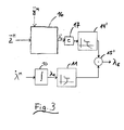
- Fig. 1 are some, relevant to the process according to the invention variables shown schematically.
- a motorcycle 2 drives in an inclined position.
- a tire 3 of the motorcycle 2 is shown cut.
- Line 4 represents the direction of the road normal
- line 5 indicates the axis of symmetry the bike again.
- the motorcycle fixed coordinate system by the motorcycle fixed vertical axis z M which runs parallel to the axis of symmetry of the motorcycle 5, and the perpendicular, motorcycle fixed transverse axis y M indicated.
- Line 6 represents the joint line projected in the yz plane between the center of gravity SP of the motorcycle 2 and the wheel contact point RAP.
- the total control angle ⁇ tot corresponds to the angle between the road normal 4 and the vehicle symmetry plane 5, the physically effective roll angle ⁇ th corresponds to the angle between the road normal 4 and line 6.
- one or more sensors 7 are / are arranged, eg a roll rate sensor for determination the motorcycle- fixed roll rate ⁇ M and / or a yaw rate sensor for determining the motorcycle- fixed yaw rate ⁇ M.
- one or more sensors or a sensor cluster 8 may be arranged on the motorcycle 2, in particular in the region of the center of gravity SP, eg a yaw rate sensor for determining the motorcycle- fixed yaw rate ⁇ M and / or acceleration sensor (s) for determining the motorcycle- fixed vertical acceleration z ⁇ M and / or the motorcycle fixed lateral acceleration ⁇ M.
- a yaw rate sensor for determining the motorcycle- fixed yaw rate ⁇ M and / or acceleration sensor (s) for determining the motorcycle- fixed vertical acceleration z ⁇ M and / or the motorcycle fixed lateral acceleration ⁇ M.
- acceleration sensor s
- the position of the roll rate sensor or the position of the yaw rate sensor on the motorcycle 2 is not relevant.
- the total roll angle ⁇ tot is approximately 10% to 20% above the physically effective roll angle ⁇ th .
- the tire-related additional roll angle ⁇ ZS is on the order of about 10% to 20% of the physically active roll angle ⁇ th . Since ⁇ ZS is small compared to ⁇ th , the total roll angle ⁇ ges is often approximated by the physically effective roll angle ⁇ th : ⁇ ges ⁇ ⁇ th
- a first embodiment of a method according to the invention is shown schematically.
- the time integration 10 of the motorcycle- fixed roll rate ⁇ M is a first calculation result (first roll angle ⁇ 1 ).
- the calculation result ⁇ 1 is filtered with high-pass filter 11, which for example has a cut-off frequency f separation of 0.05 Hz.
- the second calculation result results as a function 13 of the product 12 of motor-vehicle-fixed yaw rate ⁇ M and vehicle speed v of the motorcycle.
- the calculation result ⁇ 1 of the time integration 10 of the motorcycle- fixed roll rate ⁇ M and the calculation result ⁇ 2 of a function 13 of the product 12 of motorcycle- fixed yaw rate ⁇ M and vehicle speed v are added (block 15).
- the calculation of the first roll angle ⁇ 1 by integration 10 of the motorcycle- fixed roll rate ⁇ M applies to both stationary and non-stationary ride.
- the calculation by the integration 10 of the measuring error of the rolling rate ⁇ M is not long-term stable , ie the result is only valid for a short time.
- the increase in the measurement error is between 1 degree / minute and 1 degree / second.
- the functions Integration 10 and high-pass filter 11 can be converted into an equivalent low-pass filter with additional gain according to an embodiment, not shown.
- the filters 11, 14 used are usually PT 1 components of the first order.
- the separation frequency f separation is, for example, in the range of about 0.01 Hz to about 0.10 Hz.
- a numerically determined characteristic curve is used (block 13) to determine from the product (block 12) of motor-vehicle-fixed yaw rate ⁇ M and vehicle speed v the roll angle ⁇ th (according to in Fig. 2 illustrated embodiment, the roll angle ⁇ 2 ) to determine.
- a second embodiment of a method according to the invention is shown schematically.
- the time integration 10 of the motorcycle- fixed roll rate ⁇ M is the first calculation result (the first roll angle ⁇ 1 ), and here, for example, the first roll angle ⁇ 1 with a high-pass filter 11, for example, with a cutoff frequency f separation of 0.05 Hz, filtered.
- the second calculation result (the second roll angle variable ⁇ 2 ' ) is essentially determined from the motorcycle- fixed acceleration in the z-direction z M (block 16).
- the second roll angle size ⁇ 2 ' in block 17 can be multiplied by an empirical factor c.
- the second calculation result ⁇ 2 ' with a low-pass filter 14' for example, with the same corner frequency f separation as that of the high-pass filter 11, for example, 0.05 Hz, filtered.
- the filters 11, 14 'used are usually PT 1 components of the first order.
- the separation frequency f separation is, for example, in the range of about 0.01 Hz to about 0.10 Hz.
- ⁇ th arccos G z ⁇ M ⁇ - 1 ⁇ sign y ⁇ M
- sign (X) is the sign function, which has the value “1” if X is greater than zero, which is “0” if X equals zero, and which is "-1" if X is less than zero ,
- the total roll angle ⁇ ges can be approximated by the physically active roll angle ⁇ th : ⁇ ges ⁇ ⁇ th
- the second roll angle quantity ⁇ 2 ' is determined according to equation (9) (block 16).
- a third embodiment of a method according to the invention is shown schematically.
- the time integration 10 of the motorcycle- fixed roll rate ⁇ M is the first calculation result (the first roll angle ⁇ 1 ), and here, for example, the first roll angle ⁇ 1 with a high-pass filter 11, for example, with a cutoff frequency f separation of 0.05 Hz, filtered.
- the first roll angle ⁇ 1 with a high-pass filter 11, for example, with a cutoff frequency f separation of 0.05 Hz, filtered.
- the second calculation result (the second roll angle variable ⁇ 2 " ) is determined from two motorcycle- fixed accelerations, in particular a motorcycle- fixed acceleration in the z-direction z M and a motor-wheel-fixed acceleration in the y-direction ⁇ M (block 20) ).
- the second calculation result ⁇ 2 " is filtered with a low-pass filter 14", for example with the same corner frequency f separation as that of the high-pass filter 11, for example 0.05 Hz.
- the filters 11, 14 "used are usually PT 1 components of the first order
- the separation frequency f separation is, for example, in the range from about 0.01 Hz to about 0.10 Hz.
- the calculation of the second roll angle ⁇ 2 " from a motorcycle- fixed acceleration in the z-direction z ⁇ M and a motorcycle- fixed acceleration in the y-direction ⁇ M applies only to stationary cornering .
- the calculation includes the tire geometry and the dynamic tire behavior of the motorcycle.
- the factor k depends on the tire geometry and the dynamic tire behavior of the motorcycle.
- An advantage of the method according to the invention is that the roll angle ⁇ E of the motorcycle without delay, apart from time delays caused by the sensors, is present. Both in stationary and transient driving conditions, the roll angle ⁇ E can be determined. In addition, the accuracy of the roll angle determined by combining two calculation methods is greater than is possible with a single measurement method.
- a further advantage is that the production costs of a device for implementing the method according to the invention are significantly lower in comparison with high-precision inertial sensors with the same accuracy.
- a sensor cluster which For example, from the use in electronic stability programs (ESP) in passenger cars already known.
- ESP electronic stability programs
- Such a sensor cluster usually provides a rotation rate signal and one or two acceleration signals.
- Such a sensor cluster can optionally be installed rotated by 90 degrees.
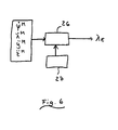
- the invention also relates to a method for determining the roll angle of a motorcycle while driving from the product of motorcycle-fixed yaw rate and driving speed of the motorcycle.
- a corresponding embodiment is shown schematically. From a motorcycle- fixed yaw rate ⁇ M and the vehicle speed v of the motorcycle, the product is formed (block 23). From the product is determined by means of a functional relationship, which is for example given in the form of a characteristic, a roll angle size (block 24). After filtering the calculation result with low-pass filter 25 results in the roll angle ⁇ E of the motorcycle.
- Filter 25 is usually a first order PT 1 member.
- the corner frequency is for example in the range of about 1 Hz.
- a combination of multiple filters is used to lower the signal peaks in fast slalom driving: a low-pass filter (corner frequency about 0.05 Hz), a high-pass filter (corner frequency about 0.05 Hz, gain 0.5), addition of both signals and possibly further filtering with a low-pass filter (corner frequency about 1 Hz) for signal smoothing.
- the roll angle ⁇ is a function f of the product ⁇ M ⁇ v of motorcycle- fixed yaw rate ⁇ M and vehicle speed v of the motorcycle (see equation (7)).
- a numerically determined characteristic curve is used (block 24) in order to determine the roll angle ⁇ from the product (block 23) of motorcycle- fixed yaw rate ⁇ M and vehicle speed v.
- the manufacturing cost of the device for implementing the method (determination of the roll angle of the product of motorized yaw rate and driving speed) are significantly lower with the same accuracy compared with high-precision inertial sensors.
- the position of the sensors on the motorcycle is not relevant, since the rotation rate is the same on the entire vehicle.
- the invention also relates to a method for checking the plausibility of a roll angle determination algorithm.
- the roll angle for the stationary driving state ie, the second roll angle size
- the roll angle for the stationary driving state can be determined in a redundant manner using different methods.
- a roll angle variable ⁇ 2 or ⁇ 2 " can be determined from the motorcycle- fixed yaw rate ⁇ M and the vehicle speed v as well as from the motorcycle- fixed lateral acceleration ⁇ M and the motorcycle- fixed lateral acceleration ⁇ M. Any choice of two or more roll angle determination methods is conceivable.
- an estimation of the trustworthiness of the roll angle ⁇ E determined by means of the roll angle size (n) is possible.
- the plausibility check / comparison may detect a sensor error. If there is a significant difference between the rolling angle variables ⁇ 2 , ⁇ 2 ' , ⁇ 2 " determined in a plurality of ways, it is possible to conclude that one of the acceleration sensors or yaw rate sensors malfunctions.
- the rolling rate ⁇ M must be zero during this period. Thus, an offset of the roll rate sensor can be determined and compensated.
- the integral of the roll rate ⁇ M is zero degrees.
- the linearity error of the roll rate sensor can be determined.
- a moving motorcycle must always be in an equilibrium position. This is necessary for both straight and cornering.
- the current driving situation is estimated in block 27 using one or more of the following variables: engine speed, engine torque, steering angle, vehicle speed v, vehicle acceleration, wheel speeds ⁇ i , road condition, wheel slip, vehicle load, road inclination.
- This assessment then flows into the calculation 26 of the roll angle ⁇ E.
- Fig. 7 an exemplary method for the adaptive calculation of a roll angle ⁇ E is shown schematically. To ensure a high accuracy, a combination of different methods for calculating the roll angle ⁇ E is used. At the same time, measurements of the roll rate ⁇ M , the yaw rate ⁇ M and the accelerations in the z and y directions z ⁇ M , ⁇ M are carried out, eg with a sensor cluster. The integral 30 of the roll rate ⁇ M is formed and the result ⁇ 1 is filtered with a high-pass filter 31.
- Properties of the system eg filter characteristics
Landscapes
- Engineering & Computer Science (AREA)
- Mechanical Engineering (AREA)
- Transportation (AREA)
- Physics & Mathematics (AREA)
- Automation & Control Theory (AREA)
- Mathematical Physics (AREA)
- Control Of Driving Devices And Active Controlling Of Vehicle (AREA)
- Regulating Braking Force (AREA)
Claims (21)
- Procédé utilisé pour déterminer l'angle de roulis d'une moto, dans lequel au moins une vitesse (v) du véhicule et un taux de lacet (ψ .M ) du véhicule sont déterminés,
caractérisé en ce que
un taux de roulis (λ .M ) du véhicule est déterminé en particulier au moyen d'un capteur de taux de rotation,
à partir du taux de roulis (λ .M ), une première grandeur d'angle de roulis (λ1 ) est déterminée, le taux de roulis (λ .M ) étant filtré à l'aide d'un filtre passe-haut, en particulier dont la fréquence de coupure est d'environ 0,01 Hz, avant d'intervenir dans le calcul de la première grandeur (λ1 ) d'angle de roulis,
à partir du produit (12) du taux de lacet (ψ .M ) déterminé en particulier par un capteur de taux de rotation et de la vitesse (v) du véhicule, une deuxième grandeur (λ2 ) d'angle de roulis est déterminée sans recourir à une accélération transversale mesurée et
l'angle de roulis (λE ) est calculé à partir des grandeurs (λ1 , λ2 ) d'angle de roulis, en particulier par addition (15). - Procédé selon la revendication 1, caractérisé en ce que la première grandeur (λ1 ) d'angle de roulis est calculée par intégration (10) temporelle du taux de roulis (λ.M ).
- Procédé selon les revendications 1 ou 2, caractérisé en ce que la première grandeur (λ1 ) d'angle de roulis est filtrée à l'aide d'un filtre passe-haut (11) avant d'intervenir dans le calcul de l'angle de roulis (λE ).
- Procédé selon au moins l'une des revendications 1 à 3, caractérisé en ce que la deuxième grandeur (λ2 ) d'angle de roulis est filtrée à l'aide d'un filtre passe-bas (14) avant d'intervenir dans le calcul de l'angle de roulis (λE ).
- Procédé selon la revendication 4, caractérisé en ce que la fréquence de coupure (fTrenn) du filtre passe-bas (14) utilisé pour filtrer la deuxième grandeur (λ2 ) d'angle de roulis est identique ou sensiblement identique à la fréquence de coupure du filtre passe-haut (10) utilisé pour filtrer la première grandeur (λ1 ) d'angle de roulis.
- Procédé selon au moins l'une des revendications 1 à 5, caractérisé en ce que la deuxième grandeur d'angle de roulis est déterminée à partir du taux de lacet (ψ .M ), de la vitesse (v) du véhicule et de l'accélération verticale (z ..M ) du véhicule.
- Procédé selon au moins l'une des revendications 1 à 6, caractérisé en ce que la deuxième grandeur (λ2 ) d'angle de roulis est déterminée à partir de la ou des grandeurs caractéristiques de la dynamique de roulage,
à l'aide d'une ligne caractéristique (13) conservée dans un appareil de commande, d'un champ de caractéristiques conservé dans un appareil de commande ou
d'un algorithme de calcul. - Procédé selon au moins l'une des revendications 1 à 7, caractérisé en ce que
au moins une autre deuxième grandeur (λ2 ") d'angle de roulis est déterminée
à partir de l'accélération verticale (z ..M ) du véhicule ou
à partir d'une accélération verticale et d'une accélération transversale (z ..M , y ..M ) du véhicule,
ces deuxièmes grandeurs (λ2 , λ2 ") d'angle de roulis étant utilisées pour une vérification de la plausibilité de l'angle de roulis (λE ), et en particulier en ce que pour la vérification de la plausibilité, on effectue une comparaison des deuxièmes grandeurs (λ2 , λ2 ") d'angle de roulis déterminées de manières différentes. - Procédé selon la revendication 8, caractérisé en ce qu'on effectue une comparaison des deuxièmes grandeurs (λ2 , λ2 ") déterminées de manières différentes et en ce que le fonctionnement défectueux d'un capteur d'accélération ou d'un capteur de taux de rotation est détecté à l'aide de la comparaison.
- Procédé selon au moins l'une des revendications 1 à 9, caractérisé en ce que les valeurs déterminées de l'accélération sont utilisées pour déterminer un décalage du capteur de taux de rotation qui détermine le taux de roulis (λ .M ).
- Procédé selon la revendication 10, caractérisé en ce qu'à l'aide du décalage déterminé, on détermine une erreur de linéarité du taux de roulis.
- Procédé selon au moins l'une des revendications 1 à 11, caractérisé en ce que l'angle de roulis (λE ) est calculé par sommation pondérée (37) des deux ou plusieurs grandeurs (λ1 , λ2 1, λ2 2) d'angle de roulis, en particulier filtrées à l'aide d'un filtre passe-haut (31) ou d'un filtre passe-bas (33, 35), des paramètres de pondération (P1, P2, P3) pondérant les différentes grandeurs (λ1 , λ2 1, λ2 2) d'angle de roulis étant prévues et étant elles-mêmes adaptées en fonction de la situation de roulage (27) en cours, détectée à l'aide d'au moins l'une des grandeurs suivantes : vitesse de rotation du moteur, couple du moteur, angle de braquage, vitesse (v) du véhicule, accélération du véhicule, vitesse de rotation des roues (ωi ), état de la chaussée, taux de roulis (λ .M ), taux de lacet (ψ .M ), accélération de l'angle de roulis, accélération de l'angle de lacet, angle de roulis (λE ), patinage des roues, charge du véhicule et pente de la chaussée.
- Procédé selon la revendication 12, caractérisé en ce que les propriétés et en particulier les fréquences de coupure des filtres (31, 33, 35) utilisés pour filtrer les grandeurs (λ1 , λ2 1, λ2 2) d'angle de roulis sont sélectionnées en fonction de la situation de roulage (27) en cours.
- Dispositif en vue de la détermination de l'angle de roulis d'une moto, comprenant au moins une unité d'évaluation, au moins un moyen de détermination de la vitesse (v) du véhicule et un moyen de détermination du taux de lacet (ψ .M ) du véhicule,
caractérisé en ce que
le dispositif comporte un moyen de détermination du taux de roulis (λ .M ) du véhicule et
en ce que la ou les unités d'évaluation comprennent un circuit additif (15) par lequel au moins deux grandeurs (λ1 , λ2 ) d'angle de roulis sont additionnées pour former un angle de roulis (λE ),
une première grandeur (λ1 ) d'angle de roulis étant déterminée à partir du taux de roulis (λ .M ) du véhicule,
le taux de roulis (λ .M ) étant filtré à l'aide d'un filtre passe-haut et en particulier dont la fréquence de coupure est d'environ 0,01 Hz avant d'intervenir dans le calcul de la première grandeur (λ1 ) d'angle de roulis, et
une deuxième grandeur (λ2 ) d'angle de roulis étant déterminée à partir du produit du taux de lacet (ψ .M ) et de la vitesse (v) du véhicule sans recourir à une accélération transversale mesurée. - Dispositif selon la revendication 14, caractérisé en ce qu'au moins une unité d'évaluation comporte un filtre passe-haut par lequel le taux de roulis (λ .M ) est filtré.
- Dispositif selon les revendications 14 ou 15, caractérisé en ce qu'au moins une unité d'évaluation comporte un circuit intégrateur par lequel la première grandeur (λ1 ) d'angle de roulis est déterminée par intégration (10) du taux de roulis (λ .M ) en particulier filtré.
- Dispositif selon au moins l'une des revendications 14 à 16, caractérisé en ce qu'au moins une unité d'évaluation comporte un filtre passe-haut (11) par lequel la première grandeur (λ1 ) d'angle de roulis est filtrée avant d'intervenir dans le calcul de l'angle de roulis (λE ).
- Dispositif selon au moins l'une des revendications 14 à 17, caractérisé en ce qu'au moins une unité d'évaluation comporte un filtre passe-bas (14) par lequel la deuxième grandeur (λ2 ) d'angle de roulis est filtrée avant d'intervenir dans le calcul de l'angle de roulis (λE ).
- Dispositif selon la revendication 18, caractérisé en ce que le filtre passe-bas (14) qui est utilisé pour filtrer la deuxième grandeur (λ2 ) d'angle de roulis possède une fréquence de coupure (fTrenn) égale ou sensiblement égale à celle du filtre passe-haut (11) utilisé pour filtrer la première grandeur (λ1 ) d'angle de roulis.
- Dispositif selon au moins l'une des revendications 14 à 19, caractérisé en ce qu'au moins une unité d'évaluation comporte un circuit par lequel la deuxième grandeur (λ2 ) d'angle de roulis est déterminée
à partir du taux de lacet (ψ .M ) et de la vitesse (v) du véhicule, en particulier à l'aide d'une ligne caractéristique (13) ou d'un champ de caractéristiques ou
à partir du taux de lacet (ψ .M ), de la vitesse (v) du véhicule et de l'accélération verticale (z ..M ) du véhicule. - Utilisation du procédé selon au moins l'une des revendications 1 à 13 dans l'un des systèmes suivants d'une moto : système de freinage à commande électronique, système d'éclairage en virage, système de train de roulement, système électrique de braquage et système de régulation de la dynamique de roulage.
Applications Claiming Priority (5)
| Application Number | Priority Date | Filing Date | Title |
|---|---|---|---|
| DE102006008204 | 2006-02-22 | ||
| DE102006012533 | 2006-03-18 | ||
| DE102006047737 | 2006-10-06 | ||
| DE102006061483.6A DE102006061483B4 (de) | 2006-02-22 | 2006-12-23 | Verfahren und Vorrichtung zur Bestimmung des Rollwinkels eines Kraftrades |
| PCT/EP2007/051545 WO2007096319A1 (fr) | 2006-02-22 | 2007-02-19 | Procédé et dispositif de détermination de l'angle de roulis d'un motocycle |
Publications (2)
| Publication Number | Publication Date |
|---|---|
| EP1989086A1 EP1989086A1 (fr) | 2008-11-12 |
| EP1989086B1 true EP1989086B1 (fr) | 2015-05-20 |
Family
ID=38042694
Family Applications (1)
| Application Number | Title | Priority Date | Filing Date |
|---|---|---|---|
| EP07704629.0A Active EP1989086B1 (fr) | 2006-02-22 | 2007-02-19 | Procédé et dispositif de détermination de l'angle de roulis d'un motocycle |
Country Status (4)
| Country | Link |
|---|---|
| US (1) | US8155798B2 (fr) |
| EP (1) | EP1989086B1 (fr) |
| DE (1) | DE102006061483B4 (fr) |
| WO (1) | WO2007096319A1 (fr) |
Cited By (3)
| Publication number | Priority date | Publication date | Assignee | Title |
|---|---|---|---|---|
| WO2017149158A1 (fr) | 2016-03-04 | 2017-09-08 | Continental Teves Ag & Co. Ohg | Procédé permettant de déterminer l'angle de roulis d'une moto |
| DE102016211427A1 (de) | 2016-06-27 | 2017-12-28 | Robert Bosch Gmbh | Verfahren zum Betreiben eines Zweirads, Vorrichtung, Zweirad |
| DE102016220559A1 (de) | 2016-10-20 | 2018-04-26 | Conti Temic Microelectronic Gmbh | Verfahren und System zur Ermittlung eines Rollwinkels eines Zweirads während einer Kurvenfahrt |
Families Citing this family (38)
| Publication number | Priority date | Publication date | Assignee | Title |
|---|---|---|---|---|
| WO2007107935A1 (fr) * | 2006-03-21 | 2007-09-27 | Koninklijke Philips Electronics N.V. | Appareil et procede pour determiner l'angle de roulis de motocycle |
| US8494747B2 (en) | 2007-03-16 | 2013-07-23 | Continental Teves Ag & Co. Ohg | Method and device for stabilizing a single-track motor vehicle |
| DE102008011575A1 (de) | 2007-03-16 | 2008-09-18 | Continental Teves Ag & Co. Ohg | Verfahren und Vorrichtung zur Stabilisierung eines einspurigen Kraftfahrzeugs |
| AT505363B1 (de) * | 2007-06-14 | 2013-02-15 | Zizala Lichtsysteme Gmbh | Verfahren und messanordnung zur ermittlung des rollwinkels eines einspurigen kraftfahrzeuges |
| DE102008056665A1 (de) | 2007-12-11 | 2009-06-18 | Continental Teves Ag & Co. Ohg | Verfahren zur automatischen Steuerung einer Kupplung eines Kraftrades sowie Kraftrad |
| US20090299546A1 (en) * | 2008-05-28 | 2009-12-03 | Hac Aleksander B | Dynamic-based method of estimating the absolute roll angle of a vehicle body |
| US20090299579A1 (en) * | 2008-05-28 | 2009-12-03 | Hac Aleksander B | Kinematic-based method of estimating the absolute roll angle of a vehicle body |
| JP4960929B2 (ja) * | 2008-07-02 | 2012-06-27 | 壽夫 浅海 | 自動二輪車のブレーキ制御装置及び挙動解析装置 |
| DE102008043794A1 (de) | 2008-11-17 | 2010-05-20 | Robert Bosch Gmbh | Verfahren und Vorrichtung zum Bestimmen des Schräglagewinkels eines Zweiradfahrzeugs |
| DE102009055776A1 (de) * | 2009-11-25 | 2011-05-26 | Conti Temic Microelectronic Gmbh | Verfahren zur Schätzung des Rollwinkels in einem fahrenden Fahrzeug |
| EP3290310B1 (fr) * | 2009-12-25 | 2021-08-18 | Yamaha Hatsudoki Kabushiki Kaisha | Procédé de détermination de caractéristiques de conducteur |
| DE102011076640A1 (de) * | 2010-09-14 | 2012-03-15 | Robert Bosch Gmbh | Verfahren zur Bremsmomentenregelung in einem Zweiradfahrzeug bei Schräglagenfahrt |
| DE102012201802A1 (de) | 2012-02-07 | 2013-08-08 | Robert Bosch Gmbh | Fahrerassistenzsystem für ein Zweirad zur Schräglagenwarnung |
| ITVR20120131A1 (it) * | 2012-06-29 | 2013-12-30 | Univ Padova | Metodo e dispositivo per la determinazione dell'angolo di rollio di un veicolo |
| DE102012211963A1 (de) * | 2012-07-10 | 2014-01-30 | Robert Bosch Gmbh | Verfahren zur Stabilisierung eines Zweirads bei Kurvenfahrt |
| WO2014017138A1 (fr) * | 2012-07-25 | 2014-01-30 | ボッシュ株式会社 | Procédé et dispositif anti-renversement pour véhicule à deux roues |
| GB2510417B (en) * | 2013-02-04 | 2016-06-15 | Jaguar Land Rover Ltd | Method and system of angle estimation |
| US8844346B1 (en) * | 2013-03-08 | 2014-09-30 | The Goodyear Tire & Rubber Company | Tire load estimation system using road profile adaptive filtering |
| US10023103B2 (en) | 2013-09-13 | 2018-07-17 | J.W. Speaker, Corporation | Systems and methods for illumination control and distribution during a vehicle bank |
| EP2886407A1 (fr) * | 2013-12-18 | 2015-06-24 | x-log Elektronik GmbH | Estimation de l'angle de roulis d'un véhicule à simple voie |
| JP5996572B2 (ja) * | 2014-03-27 | 2016-09-21 | 本田技研工業株式会社 | 車体のロール角推定装置 |
| US10283007B2 (en) | 2014-06-16 | 2019-05-07 | Honda Motor Co., Ltd. | Training system and method for motorcycle riding |
| US9340211B1 (en) | 2014-12-03 | 2016-05-17 | The Goodyear Tire & Rubber Company | Intelligent tire-based road friction estimation system and method |
| DE102015202115A1 (de) * | 2015-02-06 | 2016-08-11 | Robert Bosch Gmbh | Verfahren zur Bestimmung des Schräglagenwinkels eines Zweirads |
| GB2536008B (en) | 2015-03-03 | 2019-06-12 | Jaguar Land Rover Ltd | Vehicle state estimation apparatus and method |
| JP6502782B2 (ja) * | 2015-07-31 | 2019-04-17 | Kyb株式会社 | バンク角度検知装置およびバンク角度検知方法 |
| DE102015216990A1 (de) | 2015-09-04 | 2017-03-09 | Continental Teves Ag & Co. Ohg | Verfahren und Vorrichtung zur Bestimmung des Schräglagenwinkels eines Kraftrades |
| WO2017070426A1 (fr) * | 2015-10-23 | 2017-04-27 | Sri International | Robot et système de commande de robot |
| US9840118B2 (en) | 2015-12-09 | 2017-12-12 | The Goodyear Tire & Rubber Company | Tire sensor-based robust road surface roughness classification system and method |
| EP3762801A4 (fr) | 2018-03-07 | 2021-12-08 | Lit Motors Corporation | Procédé de commande intégré permettant de maintenir en équilibre un véhicule à deux roues à l'aide de gyroscopes inertiels de commande d'orientation et de systèmes de direction à commande électrique |
| JP6992159B2 (ja) * | 2018-03-28 | 2022-02-15 | 本田技研工業株式会社 | 鞍乗型車両用物体検知システムおよび鞍乗型車両 |
| DE102018212601A1 (de) * | 2018-07-27 | 2020-01-30 | Zf Friedrichshafen Ag | Verfahren zur Ausgabe eines Signals in Abhängigkeit von einem Beschleunigungssignal sowie Steuergerät zur Ausgabe eines Signals in Abhängigkeit von einem Beschleunigungssignal |
| DE102018213298A1 (de) * | 2018-08-08 | 2020-02-13 | Robert Bosch Gmbh | Motorrad sowie Verfahren und Steuergerät zum Steuern eines aktiven Lenkbeeinflussungssystems eines Motorrads |
| DE102019101392A1 (de) * | 2019-01-21 | 2020-07-23 | Bayerische Motoren Werke Aktiengesellschaft | Verfahren zur Traktionskontrolle eines einspurigen Kraftfahrzeugs unter Berücksichtigung des Schräglaufwinkels des Hinterrades |
| DE102020106525A1 (de) | 2020-03-10 | 2021-09-16 | Bayerische Motoren Werke Aktiengesellschaft | Verfahren und Vorrichtung zur Schätzung einer Winkel-Lage eines einspurigen Fahrzeugs |
| JP7235015B2 (ja) * | 2020-07-17 | 2023-03-08 | トヨタ自動車株式会社 | 自動操舵システム |
| KR20240015079A (ko) * | 2021-04-29 | 2024-02-02 | 리트 모터스 코포레이션 | 2-바퀴형 자가-균형 차량을 위한 요 댐퍼 |
| CN114322931B (zh) * | 2021-11-23 | 2024-05-17 | 潍柴动力股份有限公司 | 坡度传感器信号的处理方法、装置、设备、系统及介质 |
Citations (1)
| Publication number | Priority date | Publication date | Assignee | Title |
|---|---|---|---|---|
| DE10350047A1 (de) * | 2003-10-27 | 2005-05-25 | Schubach, Rudolf, Dipl.-Ing. | Vorrichtung zum Messen der Kurvenneigung und der Momentangeschwindigkeit von Zweirädern |
Family Cites Families (14)
| Publication number | Priority date | Publication date | Assignee | Title |
|---|---|---|---|---|
| DE4244112C2 (de) * | 1992-12-24 | 2000-10-12 | Bayerische Motoren Werke Ag | Antiblockierregelsystem für Motorräder |
| JP3855441B2 (ja) * | 1998-03-06 | 2006-12-13 | トヨタ自動車株式会社 | 車体ロール評価値演算装置 |
| US6292759B1 (en) * | 1998-11-19 | 2001-09-18 | Delphi Technologies, Inc. | Vehicle attitude angle estimation using sensed signal blending |
| JP2001074449A (ja) * | 1999-09-06 | 2001-03-23 | Honda Motor Co Ltd | 車両の傾斜角度検出装置 |
| US6438463B1 (en) * | 1999-09-06 | 2002-08-20 | Honda Giken Kogyo Kabushiki Kaisha | Process for determining lateral overturning of vehicle, and system for detecting inclination angle of vehicle body |
| KR100474180B1 (ko) * | 1999-12-16 | 2005-03-09 | 지멘스 악티엔게젤샤프트 | 거의 수평인 회전축을 중심으로 회전하는 물체의 회전절대각을 결정하기 위한 방법 및 장치 |
| DE10003832A1 (de) * | 2000-01-28 | 2001-08-02 | Rudolf Schubach | Meßgerät zum kontinuierlichen Messen der Kurvenneigung bei Motorrädern |
| SE523023C2 (sv) * | 2000-04-12 | 2004-03-23 | Nira Dynamics Ab | Metod och anordning för att med rekursiv filtrering bestämma en fysikalisk parameter hos ett hjulfordon |
| SE0004515D0 (sv) | 2000-06-28 | 2000-12-06 | Nira Automotive Ab | Roll angle indicator |
| DE10039978C2 (de) | 2000-08-16 | 2002-05-08 | Rudolf Schubach | Vorrichtung zum Messen des Neigungswinkels und/oder der Beschleunigung |
| DE10115217C1 (de) * | 2001-03-28 | 2002-08-14 | Bosch Gmbh Robert | Verfahren zum Bestimmen der Winkellage eines Fahrzeugs |
| DE10350046A1 (de) | 2003-10-27 | 2005-05-25 | Schubach, Rudolf, Dipl.-Ing. | Vorrichtung zum dynamischen Messen des Rollwinkels von Fahrzeugen |
| DE102004021590A1 (de) * | 2004-05-03 | 2005-12-01 | Continental Aktiengesellschaft | Vorrichtung und Verfahren zur Bestimmung des Neigungswinkels eines Zweirades sowie Verfahren zur Niveauregulierung eines gefederten Zweirades |
| US20060155440A1 (en) * | 2005-01-10 | 2006-07-13 | Siemens Vdo Automotive Corporation | Roll angle plausibility |
-
2006
- 2006-12-23 DE DE102006061483.6A patent/DE102006061483B4/de active Active
-
2007
- 2007-02-19 WO PCT/EP2007/051545 patent/WO2007096319A1/fr active Application Filing
- 2007-02-19 EP EP07704629.0A patent/EP1989086B1/fr active Active
- 2007-02-19 US US12/280,229 patent/US8155798B2/en active Active
Patent Citations (1)
| Publication number | Priority date | Publication date | Assignee | Title |
|---|---|---|---|---|
| DE10350047A1 (de) * | 2003-10-27 | 2005-05-25 | Schubach, Rudolf, Dipl.-Ing. | Vorrichtung zum Messen der Kurvenneigung und der Momentangeschwindigkeit von Zweirädern |
Cited By (3)
| Publication number | Priority date | Publication date | Assignee | Title |
|---|---|---|---|---|
| WO2017149158A1 (fr) | 2016-03-04 | 2017-09-08 | Continental Teves Ag & Co. Ohg | Procédé permettant de déterminer l'angle de roulis d'une moto |
| DE102016211427A1 (de) | 2016-06-27 | 2017-12-28 | Robert Bosch Gmbh | Verfahren zum Betreiben eines Zweirads, Vorrichtung, Zweirad |
| DE102016220559A1 (de) | 2016-10-20 | 2018-04-26 | Conti Temic Microelectronic Gmbh | Verfahren und System zur Ermittlung eines Rollwinkels eines Zweirads während einer Kurvenfahrt |
Also Published As
| Publication number | Publication date |
|---|---|
| DE102006061483B4 (de) | 2024-01-25 |
| US8155798B2 (en) | 2012-04-10 |
| DE102006061483A1 (de) | 2007-08-23 |
| EP1989086A1 (fr) | 2008-11-12 |
| US20090222164A1 (en) | 2009-09-03 |
| WO2007096319A1 (fr) | 2007-08-30 |
Similar Documents
| Publication | Publication Date | Title |
|---|---|---|
| EP1989086B1 (fr) | Procédé et dispositif de détermination de l'angle de roulis d'un motocycle | |
| EP1692026B1 (fr) | Procede et systeme de surveillance d'un dispositif de mesure dispose dans un vehicule a roues | |
| EP1157899B1 (fr) | Procédé et système de sécurité pour la détection d'un tonneau et pour le déclenchement d'un system de sécurité dans un véhicule automobile | |
| EP2681086B1 (fr) | Système de capteurs de véhicule intelligent | |
| EP2303663B1 (fr) | Dispositif et procédé de détermination de l état de conduite d' un véhicule | |
| DE102005047021B3 (de) | Anordnung zur Bestimmung eines absoluten Neigungswinkels gegenüber der Horizontalen | |
| DE102009022592B4 (de) | Verfahren zur Ermittlung des Fahrbahnreibwerts während des Betriebs eines Kraftfahrzeugs | |
| EP2978643A1 (fr) | Procédé de détermination de la vitesse de référence d'un véhicule et appareil de commande de véhicule à l'aide d'un tel procédé | |
| DE102007029870A1 (de) | Verfahren und Vorrichtung zur Reifenzustandsüberwachung | |
| DE19939872B4 (de) | Verfahren und Vorrichtung zur Sensorüberwachung insbesondere für ein ESP-System für Fahrzeuge | |
| DE102013013614A1 (de) | Elektrisches Servolenkungssystem und Lenkwinkelausgabeverfahren davon | |
| EP3134301A1 (fr) | Procédé de détermination d'un décalage d'un capteur inertiel | |
| DE19821617C1 (de) | Verfahren und Vorrichtung zur Messung des Neigungswinkels in seitlich geneigten Kurven und deren Verwendung | |
| DE102018211764A1 (de) | Verfahren zur Ermittlung und/oder zur Überwachung eines mechanischen Zustands einer Spurstangenvorrichtung | |
| WO2013127410A1 (fr) | Dispositif et procédé pour la détermination du mode de fonctionnement d'un véhicule | |
| DE102014200987A1 (de) | Verfahren zur Ermittlung der Lage des Schwerpunkts eines Fahrzeugs | |
| DE10360728A1 (de) | Verfahren und Vorrichtung zur Bestimmung eines Fahrzeugzustandes | |
| DE112015006908T5 (de) | Fahrzeugbewegungsdetektionseinrichtung | |
| EP2544935A1 (fr) | Procédé et dispositif de détection d'un écart d'un signal de vitesse de rotation d'un capteur de vitesse de rotation | |
| EP1855918A1 (fr) | Procede et dispositif pour determiner un angle de flottaison initiale pour determiner le derapage dans la detection de tonneaux | |
| DE112019007748T5 (de) | Zustandsgrößen-Berechnungsvorrichtung, Steuervorrichtung und Fahrzeug | |
| DE102004038000A1 (de) | Verfahren zur Bestimmung des Neigungswinkels eines Fahrzeuges und Verwendung desselben für die Erzeugung eines Auslösesignales für eine Sicherheitseinrichtung bei einem Überrollvorgang | |
| EP1628863B1 (fr) | Dispositif et procede pour mesurer des parametres de mouvement d'automobile | |
| DE102010038516A1 (de) | Verfahren und Vorrichtung zur Bestimmung einer Pedalstellung eines Pedals eines Fahrzeugs | |
| DE102012202545A1 (de) | Verfahren und Vorrichtung zur Abschätzung einer auf ein Kraftfahrzeug wirkenden Störkraft |
Legal Events
| Date | Code | Title | Description |
|---|---|---|---|
| PUAI | Public reference made under article 153(3) epc to a published international application that has entered the european phase |
Free format text: ORIGINAL CODE: 0009012 |
|
| 17P | Request for examination filed |
Effective date: 20080922 |
|
| AK | Designated contracting states |
Kind code of ref document: A1 Designated state(s): DE FR |
|
| DAX | Request for extension of the european patent (deleted) | ||
| RBV | Designated contracting states (corrected) |
Designated state(s): DE FR |
|
| 17Q | First examination report despatched |
Effective date: 20090319 |
|
| RIN1 | Information on inventor provided before grant (corrected) |
Inventor name: SEINIGER, PATRICK Inventor name: OLEJNIK, PETER Inventor name: KOUKES, VLADIMIR Inventor name: WINNER, HERMANN Inventor name: KREMER, MICHAEL Inventor name: KOLB, FRIEDRICH Inventor name: ECKERT, ALFRED |
|
| GRAP | Despatch of communication of intention to grant a patent |
Free format text: ORIGINAL CODE: EPIDOSNIGR1 |
|
| INTG | Intention to grant announced |
Effective date: 20150122 |
|
| GRAS | Grant fee paid |
Free format text: ORIGINAL CODE: EPIDOSNIGR3 |
|
| GRAA | (expected) grant |
Free format text: ORIGINAL CODE: 0009210 |
|
| AK | Designated contracting states |
Kind code of ref document: B1 Designated state(s): DE FR |
|
| REG | Reference to a national code |
Ref country code: DE Ref legal event code: R096 Ref document number: 502007013938 Country of ref document: DE |
|
| REG | Reference to a national code |
Ref country code: DE Ref legal event code: R097 Ref document number: 502007013938 Country of ref document: DE |
|
| PLBE | No opposition filed within time limit |
Free format text: ORIGINAL CODE: 0009261 |
|
| STAA | Information on the status of an ep patent application or granted ep patent |
Free format text: STATUS: NO OPPOSITION FILED WITHIN TIME LIMIT |
|
| 26N | No opposition filed |
Effective date: 20160223 |
|
| REG | Reference to a national code |
Ref country code: FR Ref legal event code: ST Effective date: 20161028 |
|
| PG25 | Lapsed in a contracting state [announced via postgrant information from national office to epo] |
Ref country code: FR Free format text: LAPSE BECAUSE OF NON-PAYMENT OF DUE FEES Effective date: 20160229 |
|
| REG | Reference to a national code |
Ref country code: DE Ref legal event code: R084 Ref document number: 502007013938 Country of ref document: DE |
|
| REG | Reference to a national code |
Ref country code: DE Ref legal event code: R081 Ref document number: 502007013938 Country of ref document: DE Owner name: CONTINENTAL AUTOMOTIVE TECHNOLOGIES GMBH, DE Free format text: FORMER OWNER: CONTINENTAL TEVES AG & CO. OHG, 60488 FRANKFURT, DE |
|
| REG | Reference to a national code |
Ref country code: DE Ref legal event code: R081 Ref document number: 502007013938 Country of ref document: DE Owner name: CONTINENTAL AUTOMOTIVE TECHNOLOGIES GMBH, DE Free format text: FORMER OWNER: CONTINENTAL AUTOMOTIVE TECHNOLOGIES GMBH, 30165 HANNOVER, DE |
|
| PGFP | Annual fee paid to national office [announced via postgrant information from national office to epo] |
Ref country code: DE Payment date: 20240229 Year of fee payment: 18 |