EP1987958B1 - Sealing method of liquid container, liquid container and method of manufacturing a liquid container - Google Patents
Sealing method of liquid container, liquid container and method of manufacturing a liquid container Download PDFInfo
- Publication number
- EP1987958B1 EP1987958B1 EP20080155594 EP08155594A EP1987958B1 EP 1987958 B1 EP1987958 B1 EP 1987958B1 EP 20080155594 EP20080155594 EP 20080155594 EP 08155594 A EP08155594 A EP 08155594A EP 1987958 B1 EP1987958 B1 EP 1987958B1
- Authority
- EP
- European Patent Office
- Prior art keywords
- film
- liquid container
- cover
- seal
- cover film
- Prior art date
- Legal status (The legal status is an assumption and is not a legal conclusion. Google has not performed a legal analysis and makes no representation as to the accuracy of the status listed.)
- Not-in-force
Links
- 239000007788 liquid Substances 0.000 title claims description 88
- 238000000034 method Methods 0.000 title claims description 28
- 238000007789 sealing Methods 0.000 title claims description 26
- 238000004519 manufacturing process Methods 0.000 title claims description 4
- 239000010408 film Substances 0.000 claims description 401
- 239000013039 cover film Substances 0.000 claims description 148
- 239000010410 layer Substances 0.000 claims description 54
- 239000000463 material Substances 0.000 claims description 53
- 229920005989 resin Polymers 0.000 claims description 47
- 239000011347 resin Substances 0.000 claims description 47
- 239000002344 surface layer Substances 0.000 claims description 41
- 238000002844 melting Methods 0.000 claims description 12
- 230000008018 melting Effects 0.000 claims description 12
- 238000003466 welding Methods 0.000 claims description 8
- 229920000139 polyethylene terephthalate Polymers 0.000 description 8
- 239000005020 polyethylene terephthalate Substances 0.000 description 8
- 239000000155 melt Substances 0.000 description 7
- -1 polypropylene Polymers 0.000 description 6
- 239000000758 substrate Substances 0.000 description 6
- 239000004743 Polypropylene Substances 0.000 description 5
- 150000002148 esters Chemical class 0.000 description 5
- 229920000098 polyolefin Polymers 0.000 description 5
- 229920001155 polypropylene Polymers 0.000 description 5
- 238000004891 communication Methods 0.000 description 4
- 230000000052 comparative effect Effects 0.000 description 4
- 238000010438 heat treatment Methods 0.000 description 4
- 238000009434 installation Methods 0.000 description 4
- 239000000203 mixture Substances 0.000 description 4
- 239000011358 absorbing material Substances 0.000 description 3
- 239000000853 adhesive Substances 0.000 description 3
- 230000001070 adhesive effect Effects 0.000 description 3
- 230000015572 biosynthetic process Effects 0.000 description 3
- 230000007423 decrease Effects 0.000 description 3
- 239000012530 fluid Substances 0.000 description 3
- 239000002184 metal Substances 0.000 description 3
- 229910052751 metal Inorganic materials 0.000 description 3
- 229920003002 synthetic resin Polymers 0.000 description 3
- 239000000057 synthetic resin Substances 0.000 description 3
- 239000004677 Nylon Substances 0.000 description 2
- 239000004698 Polyethylene Substances 0.000 description 2
- 238000007872 degassing Methods 0.000 description 2
- 230000009969 flowable effect Effects 0.000 description 2
- 150000002739 metals Chemical class 0.000 description 2
- 238000002156 mixing Methods 0.000 description 2
- 229920001778 nylon Polymers 0.000 description 2
- 230000000149 penetrating effect Effects 0.000 description 2
- 229920000573 polyethylene Polymers 0.000 description 2
- 238000004321 preservation Methods 0.000 description 2
- 230000000717 retained effect Effects 0.000 description 2
- 239000004065 semiconductor Substances 0.000 description 2
- 239000002356 single layer Substances 0.000 description 2
- JOYRKODLDBILNP-UHFFFAOYSA-N Ethyl urethane Chemical compound CCOC(N)=O JOYRKODLDBILNP-UHFFFAOYSA-N 0.000 description 1
- 239000003086 colorant Substances 0.000 description 1
- 230000003247 decreasing effect Effects 0.000 description 1
- 229920001971 elastomer Polymers 0.000 description 1
- 239000000806 elastomer Substances 0.000 description 1
- 239000004744 fabric Substances 0.000 description 1
- 230000002349 favourable effect Effects 0.000 description 1
- 239000003292 glue Substances 0.000 description 1
- 239000003049 inorganic solvent Substances 0.000 description 1
- 229910001867 inorganic solvent Inorganic materials 0.000 description 1
- 239000012528 membrane Substances 0.000 description 1
- 239000003960 organic solvent Substances 0.000 description 1
- 239000002245 particle Substances 0.000 description 1
- 230000035515 penetration Effects 0.000 description 1
- 229920001707 polybutylene terephthalate Polymers 0.000 description 1
- 229920005672 polyolefin resin Polymers 0.000 description 1
- 239000011148 porous material Substances 0.000 description 1
- 239000000843 powder Substances 0.000 description 1
- 238000003825 pressing Methods 0.000 description 1
- 238000007639 printing Methods 0.000 description 1
- 230000001105 regulatory effect Effects 0.000 description 1
- 239000000243 solution Substances 0.000 description 1
- 125000000391 vinyl group Chemical group [H]C([*])=C([H])[H] 0.000 description 1
- 229920002554 vinyl polymer Polymers 0.000 description 1
Images


Classifications
-
- B—PERFORMING OPERATIONS; TRANSPORTING
- B41—PRINTING; LINING MACHINES; TYPEWRITERS; STAMPS
- B41J—TYPEWRITERS; SELECTIVE PRINTING MECHANISMS, i.e. MECHANISMS PRINTING OTHERWISE THAN FROM A FORME; CORRECTION OF TYPOGRAPHICAL ERRORS
- B41J2/00—Typewriters or selective printing mechanisms characterised by the printing or marking process for which they are designed
- B41J2/005—Typewriters or selective printing mechanisms characterised by the printing or marking process for which they are designed characterised by bringing liquid or particles selectively into contact with a printing material
- B41J2/01—Ink jet
- B41J2/17—Ink jet characterised by ink handling
- B41J2/175—Ink supply systems ; Circuit parts therefor
- B41J2/17503—Ink cartridges
- B41J2/17513—Inner structure
-
- B—PERFORMING OPERATIONS; TRANSPORTING
- B41—PRINTING; LINING MACHINES; TYPEWRITERS; STAMPS
- B41J—TYPEWRITERS; SELECTIVE PRINTING MECHANISMS, i.e. MECHANISMS PRINTING OTHERWISE THAN FROM A FORME; CORRECTION OF TYPOGRAPHICAL ERRORS
- B41J2/00—Typewriters or selective printing mechanisms characterised by the printing or marking process for which they are designed
- B41J2/005—Typewriters or selective printing mechanisms characterised by the printing or marking process for which they are designed characterised by bringing liquid or particles selectively into contact with a printing material
- B41J2/01—Ink jet
- B41J2/17—Ink jet characterised by ink handling
- B41J2/175—Ink supply systems ; Circuit parts therefor
- B41J2/17503—Ink cartridges
- B41J2/1752—Mounting within the printer
- B41J2/17523—Ink connection
-
- B—PERFORMING OPERATIONS; TRANSPORTING
- B41—PRINTING; LINING MACHINES; TYPEWRITERS; STAMPS
- B41J—TYPEWRITERS; SELECTIVE PRINTING MECHANISMS, i.e. MECHANISMS PRINTING OTHERWISE THAN FROM A FORME; CORRECTION OF TYPOGRAPHICAL ERRORS
- B41J2/00—Typewriters or selective printing mechanisms characterised by the printing or marking process for which they are designed
- B41J2/005—Typewriters or selective printing mechanisms characterised by the printing or marking process for which they are designed characterised by bringing liquid or particles selectively into contact with a printing material
- B41J2/01—Ink jet
- B41J2/17—Ink jet characterised by ink handling
- B41J2/175—Ink supply systems ; Circuit parts therefor
- B41J2/17503—Ink cartridges
- B41J2/17533—Storage or packaging of ink cartridges
-
- B—PERFORMING OPERATIONS; TRANSPORTING
- B41—PRINTING; LINING MACHINES; TYPEWRITERS; STAMPS
- B41J—TYPEWRITERS; SELECTIVE PRINTING MECHANISMS, i.e. MECHANISMS PRINTING OTHERWISE THAN FROM A FORME; CORRECTION OF TYPOGRAPHICAL ERRORS
- B41J2/00—Typewriters or selective printing mechanisms characterised by the printing or marking process for which they are designed
- B41J2/005—Typewriters or selective printing mechanisms characterised by the printing or marking process for which they are designed characterised by bringing liquid or particles selectively into contact with a printing material
- B41J2/01—Ink jet
- B41J2/17—Ink jet characterised by ink handling
- B41J2/175—Ink supply systems ; Circuit parts therefor
- B41J2/17503—Ink cartridges
- B41J2/17536—Protection of cartridges or parts thereof, e.g. tape
-
- B—PERFORMING OPERATIONS; TRANSPORTING
- B41—PRINTING; LINING MACHINES; TYPEWRITERS; STAMPS
- B41J—TYPEWRITERS; SELECTIVE PRINTING MECHANISMS, i.e. MECHANISMS PRINTING OTHERWISE THAN FROM A FORME; CORRECTION OF TYPOGRAPHICAL ERRORS
- B41J2/00—Typewriters or selective printing mechanisms characterised by the printing or marking process for which they are designed
- B41J2/005—Typewriters or selective printing mechanisms characterised by the printing or marking process for which they are designed characterised by bringing liquid or particles selectively into contact with a printing material
- B41J2/01—Ink jet
- B41J2/17—Ink jet characterised by ink handling
- B41J2/175—Ink supply systems ; Circuit parts therefor
- B41J2/17503—Ink cartridges
- B41J2/17553—Outer structure
-
- B—PERFORMING OPERATIONS; TRANSPORTING
- B41—PRINTING; LINING MACHINES; TYPEWRITERS; STAMPS
- B41J—TYPEWRITERS; SELECTIVE PRINTING MECHANISMS, i.e. MECHANISMS PRINTING OTHERWISE THAN FROM A FORME; CORRECTION OF TYPOGRAPHICAL ERRORS
- B41J2/00—Typewriters or selective printing mechanisms characterised by the printing or marking process for which they are designed
- B41J2/005—Typewriters or selective printing mechanisms characterised by the printing or marking process for which they are designed characterised by bringing liquid or particles selectively into contact with a printing material
- B41J2/01—Ink jet
- B41J2/17—Ink jet characterised by ink handling
- B41J2/175—Ink supply systems ; Circuit parts therefor
- B41J2/17503—Ink cartridges
- B41J2/17559—Cartridge manufacturing
-
- Y—GENERAL TAGGING OF NEW TECHNOLOGICAL DEVELOPMENTS; GENERAL TAGGING OF CROSS-SECTIONAL TECHNOLOGIES SPANNING OVER SEVERAL SECTIONS OF THE IPC; TECHNICAL SUBJECTS COVERED BY FORMER USPC CROSS-REFERENCE ART COLLECTIONS [XRACs] AND DIGESTS
- Y10—TECHNICAL SUBJECTS COVERED BY FORMER USPC
- Y10T—TECHNICAL SUBJECTS COVERED BY FORMER US CLASSIFICATION
- Y10T428/00—Stock material or miscellaneous articles
- Y10T428/31504—Composite [nonstructural laminate]
Definitions
- the present invention relates to a method of liquid container, a method of manufacturing liquid container, a liquid container, remanufacturing method of liquid container, and remanufactured liquid container.
- an ink cartridge removably mounted in an inkjet printer (hereinafter, referred to as a printer), which is a type of liquid ejection apparatus, for example, is known.
- the ink cartridge has a container body with a substantially flat box-like shape, An ink chamber is defined in the container body to receive ink, which is liquid.
- An ink inlet hole is formed in a lower surface of the container body to allow initial filling of the ink into the ink chamber.
- An ink supply hole is also provided in the lower surface of the container body to receive an ink supply needle with the ink cartridge secured to the printer.
- a cover film is bonded to the lower surface of the container body in such a manner as to seal the ink inlet hole and the ink supply hole.
- a used ink cartridge may be remanufactured as a reusable ink cartridge by refilling the container body of the ink cartridge with ink.
- an opening is formed in the cover film at a position corresponding to the ink inlet hole using a piercing jig, before the used ink cartridge is refilled with ink. Then, a syringe, for example, is inserted into the ink inlet hole through the opening in the cover film to introduce the ink refill into the container body. Another film (a seal film) is then mounted on the cover film to close the opening and heated to be bonded to the cover film having the opening. In this manner, the opening is sealed and the ink is prevented from leaking from the opening.
- an opening is formed in a portion of the cover film corresponding to the ink supply hole by an ink supply needle.
- a seal film is welded to the cover film in such a manner that the seal film seals the opening in the cover film corresponding to the ink supply hole, in addition to the opening in the cover film corresponding to the ink inlet hole.
- the ink contaminates the cut pieces of the cover film (or the seal film) of the used ink cartridge that are formed around the opening formed by the ink supply needle.
- the portion of the cover film (or the seal film) around the opening is cleansed to remove the ink contaminating the cut pieces.
- one or more seal films are provided on the cover film. If the seal films are stacked, ink may be caught between the cut pieces of an adjacent pair of the stacked films. Since it is not easy to cleanse and remove ink from between the stacked cut pieces, some of the ink may remain at the site without being removed. Thus, when the used ink cartridge is recovered and refilled with ink refill, the remaining used ink may mix with the new ink, or the ink refill, thus changing the composition of the ink.
- US 6, 416, 152 and EP 1, 527, 282 disclose cartridges which comprise a lid in which grooves are formed. Such grooves are sealed by a sealing film.
- a method for sealing a liquid container is provided.
- the cover film is bonded to the liquid container in such a manner as to cover a hole formed in the liquid container.
- An opening is formed in the cover film in such a manner as to communicate with the hole of the liquid container.
- the method includes: preparing a seal film; and bonding the seal film to the cover film with a bonding strength smaller than the bonding strength of the cover film with respect to the liquid container in such a manner that the seal film is peelable from the cover film, thereby sealing the opening of the cover film.
- a liquid container according to claim 5 is provided.
- a method for manufacturing a liquid container is provided.
- a cover film is bonded to the liquid container in such a manner as to cover a hole formed in the liquid container.
- An opening is formed in the cover film in such a manner as to communicate with the hole of the liquid container.
- the method includes: filling the liquid container with a liquid; preparing a seal film; and bonding the seal film to the cover film with a bonding strength smaller than the bonding strength of the cover film with respect to the liquid container in such a manner that the seal film becomes peelable from the cover film, thereby sealing the opening of the cover film.
- the seal film is advantageously bonded to the cover film with a bonding strength smaller than the bonding strength of the cover film with respect to the liquid container in such a manner that the seal film becomes peelable from the cover film.
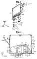
- Fig. 1 is a front perspective view showing a new ink cartridge according to one embodiment of the present invention
- Fig. 2 is a rear perspective view showing the ink cartridge shown in Fig. 1 ;
- Fig. 3 is a partially exploded perspective view showing the ink cartridge shown in Fig. 2 ;
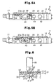
- Fig. 4 is a front view, with a part cut away, showing the ink cartridge shown in Fig. 1 ;
- Fig. 5A is a bottom view showing the new ink cartridge
- Fig. 5B is a bottom view showing a used ink cartridge
- Fig. 6 is a cross-sectional view showing a portion of the ink cartridge that has been subjected to a piercing step
- Fig. 7 is a cross-sectional view showing a portion of the ink cartridge when the ink is supplied to the ink cartridge through the opening;
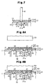
- Fig. 8A is a cross-sectional view showing a portion of the container body in which a first ink inlet hole and a second ink inlet hole have been formed before a sealing step;
- Fig. 8B is a cross-sectional view showing the portion of the container body corresponding to the first ink inlet hole and the second ink inlet hole after the sealing step;
- Fig. 9 is a front view, with a part cut away, showing a remanufactured ink cartridge
- Fig. 10 is a rear perspective view showing the remanufactured ink cartridge
- Fig. 11 is a perspective view showing the remanufactured ink cartridge in a state of being shipped;
- Fig. 12A is a cross-sectional view showing a portion of the remanufactured ink cartridge in the state of use;
- Fig. 12B is a cross-sectional view showing a portion of a comparative example of the ink cartridge shown in Fig. 12A ;
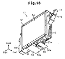
- Fig. 13 is a rear perspective view showing a remanufactured ink cartridge of a modified embodiment.
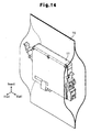
- Fig. 14 is a perspective view showing the remanufactured ink cartridge of the modified example in a state of being shipped.
- an ink cartridge 11, or a fluid container of the illustrated embodiment includes a container body 12, which is shaped substantially like a flat rectangular box and formed of synthetic resin, which is, for example, polypropylene (PP).
- a container body 12 which is shaped substantially like a flat rectangular box and formed of synthetic resin, which is, for example, polypropylene (PP).
- PP polypropylene
- an opening 12a is formed in a front surface of the container body 12.
- a film member (not shown), which is formed of thermally adhesive material, is welded to the container body 12 to substantially cover the entire opening 12a.
- a lid body 13 is detachably attached to the container body 12 from outside the film member (the side corresponding to the front surface) in such a manner that the opening 12a is shielded.
- a guide projection 16 extending in the up-and-down direction projects from a lower portion of a left surface of the container body 12.
- a printer which is a type of fluid ejection apparatus
- the guide projection 16 is received in a guide recess (not shown) formed in the cartridge holder. This guides the ink cartridge 11 when the ink cartridge 11 is mounted in the cartridge holder.
- an elastically deformable engagement lever 17 which projects diagonally to the upper left, is arranged at a position above the guide projection 16 on the left surface of the container body 12.
- An engagement piece 17a which extends horizontally (in the front-and-rear direction), projects substantially from the longitudinal center of the engagement lever 17 on a surface of the engagement lever 17.
- a substrate unit 18 is secured to a lower portion of a right surface of the container body 12.
- a circuit substrate 19 on which a semiconductor memory device is mounted is arranged on a surface of the substrate unit 18.
- the semiconductor memory device of the circuit substrate 19 stores various information regarding the ink cartridge 11 (for example, information regarding ink colors and ink containing amounts).
- Terminals 19a are provided on the surface of the circuit substrate 19.
- the terminals 19a contact connection terminals formed in the cartridge holder. This transfers various information between the circuit substrate 19 and a control device (not shown) of the printer.
- a rectangular opening 20, a first ink inlet hole 21 having a circular shape, a second ink inlet hole 22 having a circular shape, and an ink supply port 23 having a circular shape are formed in a lower surface (a hole forming surface S) of the container body 12 and arranged in this order from the right end to the left end of the lower surface.
- the ink supply port 23 has a pair of guide walls 23a each having a substantial U shape, which are provided at the right end and the left end of the ink supply port 23.
- the interior of the opening 20 defines an atmospheric air communication chamber 24, which configures a portion of an atmospheric air communication passage.
- the atmospheric air communication chamber 24 communicates with the exterior of the container body 12, or the atmospheric air, through a non-illustrated atmospheric air exposure port.
- the atmospheric air communication chamber 24 accommodates a coil spring 25, a valve body 26, and a valve support member 27 in this order from inward to outward.
- a rib 28 defines an upper ink chamber 29 and a lower ink chamber 30 in the container body 12.
- the first ink inlet hole 21 communicates with the upper ink chamber 29 and the lower ink chamber 30 through a narrow passage 21a and a narrow ink inlet port 21b, which are formed in the container body 12.
- the second ink inlet hole 22 communicates directly with the lower ink chamber 30.
- ink is introduced through the ink inlet holes 21, 22.
- the first and second ink inlet holes 21, 22 are sealed by a cover film 31 along with the opening 20 as illustrated in Figs 2 to 4 .
- the cover film 31 has a two-layer structure formed by a bonding layer film 31a and a surface layer film 31b. As illustrated in Figs. 6 and 7 , the bonding layer film 31a is welded to a lower surface of the container body 12. In this state, the surface layer film 31b is arranged on the bonding layer film 31a in such a manner that the surface layer film 31b is exposed to the exterior.
- a polyolefin-based film (a PO-based film) that melts at a predetermined temperature and exhibits improved welding performance, or a film formed of a resin material of the same type as the resin material forming the container body 12 of the ink cartridge 11, may be employed. If the container body 12 of the ink cartridge 11 is formed of an ester-based resin material, the bonding layer film 31a is formed of a resin material of the same type as the material of the container body 12, which is the ester-based resin material.
- the surface layer film 31b is formed of a polyethylene-terephthalate-based film (a PET-based film) or a nylon-based film (a NY-based film) that do not melt at the melting point of the bonding layer film 31a and exhibits enhanced heat resistance compared to the bonding layer film 31a.
- the surface layer film 31b is formed of a resin material of a type different from the type of the resin material forming the container body 12 and the bonding layer film 31a.
- the cover film 32 has a two-layer structure formed of a bonding layer film and a surface layer film.
- a polyolefin-based film (a PO-based film) may be used as the bonding layer film.
- a polyethylene-terephthalate-based film (a PET-based film) may be employed as the surface layer film.
- the interior of the ink supply port 23 accommodates an annular seal member 33 formed of elastomer or the like, a supply valve 34, and a coil spring 35.
- the seal member 33 allows penetration of the ink supply needle of the cartridge holder into the ink supply port 23.
- the supply valve 34 is brought into contact with the seal member 33.
- the coil spring 35 urges the supply valve 34 toward the seal member 33.
- the supply valve 34 is urged by the coil spring 35 to be pressed against the seal member 33, thus closing the ink supply port 23. This constantly prevents the ink from flowing from the interior of the container body 12 to the exterior through the ink supply port 23.
- the ink supply needle of the cartridge holder presses the supply valve 34 inwardly in the ink supply port 23 against the urging force of the coil spring 35.
- the supply valve 34 is thus separated from the seal member 33. This opens the ink supply port 23, allowing the ink to flow from the interior of the container body 12 to the exterior through the ink supply port 23.
- the printer consumes the ink until the ink is used up.
- the used ink cartridge 11 is removed from the cartridge holder and replaced by a new ink cartridge 11.
- the used ink cartridge 11 is then refilled with ink and remanufactured as a reusable ink cartridge without being discarded. This contributes to efficient use of resources and preservation of environments.
- a used ink cartridge 11 has an opening 41 at the center of a hole covering area 40 of the cover film 32 covering the ink supply port 23.
- the cover film 32 of the ink cartridge 11 has the opening 41 communicating with the ink supply hole 23 formed in the hole covering area 40.
- the used ink cartridge 11 is recovered in the state illustrated in Fig. 5B .
- the ink cartridge 11 is arranged in a reversed posture with the lower surface of the container body 12 facing upward, as illustrated in Fig. 6 .
- a piercing blade 46 is arranged in correspondence with the hole covering area 42 corresponding to the first ink inlet hole 21 of the cover film 31 in the vertical direction.
- Four blade portions 47 which extend radially from the axis of the blade 46, project from the distal end of the piercing blade 46, as viewed from the side corresponding to the distal end of the blade 46 along the axial direction of the blade 46.
- the blade portions 47 are spaced at regular angular intervals (which are, in the illustrated embodiment, 90 degrees each).
- the piercing blade 46 is brought closer to the lower surface of the container body 12. This causes the blade portions 47 of the piercing blade 46 to penetrate the hole covering area 42 of the first ink inlet hole 21 of the cover film 31.
- the blade portions 47 thus form a cross-shaped cut extending radially from a point coinciding with the center of the first ink inlet hole 21 in the hole covering area 42 of the cover film 31.
- the cut forms four cantilevered cut pieces 48 having mutually identical shapes.
- the cut pieces 48 suspend in the first ink inlet hole 21 separately from one another in radial directions.
- This forms an opening 49, through which refilling of the ink is performed, in the hole covering area 42 of the first ink inlet hole 21 of the cover film 31.
- the cover film 31 corresponds to a film including the opening 49, which is defined in the hole covering area 42 and communicates with the first ink inlet hole 21.
- the ink introduction nozzles N are inserted into the ink inlet holes 21, 22 through the corresponding openings 49.
- Ink refill is thus introduced into the ink chambers 29, 30, with which the ink inlet holes 21, 22 communicate.
- a laminated film 50 serving as a seal member seals the two openings 49 through which the refilling has been carried out and the opening 41 in the cover film 32 corresponding to the ink supply hole 23. In this manner, a reusable ink cartridge 11 is obtained.
- FIGS. 8A and 8B are cross-sectional views each showing the container body 12 including the first ink inlet hole 21 and the second ink inlet hole 22.
- the laminated film 50 is mounted on the cover film 31 in such a manner as to cover the openings 49 extending through the cover film 31.
- the laminated film 50 has a two-layer structure including a first film 51 and a second film 52.
- the first film 51 is molten when heated at a predetermined temperature.
- the second film 52 cannot be molten at the melting temperature of the first film 51.
- the second film 52 has an improved heat resistance compared to the first film 51.
- the first film 51 forms the outermost layer at one side of the layering directions of the films 51, 52 and the second film 52 forms the outermost layer at the other side.
- the laminated film 50 With the first film 51 maintained in contact with the cover film 31 in such a manner as to cover the ink inlet holes 21, 22 and the corresponding openings 49, the laminated film 50 is placed on the container body 12. The first film 51 is thus opposed to the container body 12 while maintained in contact with the cover film 31. At this position, the first film 51 is heated to be welded to the cover film 31. Since the second film 52 is arranged at an outer side, the second film 52, which has the improved heat resistance, maintains sealing by the laminated film 50.
- the first film 51 a polyolefin-based film (a PO-based film) that melts at a predetermined temperature and exhibits improved welding performance may be employed.
- the first film 51 is a film formed of a resin material of the same type as the resin material forming the container body 12 of the ink cartridge 11 and the bonding layer film 31a of the cover film 31 but different from the type of the material forming the surface layer film 31b of the cover film 31. If the resin materials forming the container body 12 of the ink cartridge 11 and the bonding layer film 31a of the cover film 31 are films formed of ester-based resin material, an ester-based film may be used as the first film 51.
- the first film 51 an easy-peel-open film (an EPO film) may be employed. That is, the first film 51 may be any film selected from a cohesive-peeling type film having a single layer structure in which different types of resin materials are mixed together randomly, an interlayer-peeling type film having a multiple layered film structure in which a film layer corresponding to a support layer and a film layer corresponding to a seal layer are bonded together with low bonding strength, and an interfacial-peeling type film having a single layer structure in which bonding strength and peeling strength are adjusted by regulating the mixing rate of different types of resin materials.
- an EPO film an easy-peel-open film
- the laminated film 50 is bonded to the cover film 31 through welding of the EPO film. Afterward, the EPO film may be easily peeled off the cover film 31 to expose the openings 49 when necessary.
- the second film 52 is formed by a polyethylene-terephthalate-based film (a PET-based film) or a nylon-based film (an NY-based film) that do not melt at the melting point of the aforementioned polyolefin-based film (the PO-based film) and have enhanced heat resistance compared to the polyolefin-based film. Further, the second film 52 is formed by a film formed of resin material of the same type as the resin material forming the surface layer film 31b of the cover film 31 but different from the type of the material forming the first film 51 of the laminated film 50.
- the thickness of the first film 51 which is layered with the second film 52, is set to 20 to 60 ⁇ m, and, preferably, to 25 ⁇ m.
- the thickness of the first film 51 is set to 20 to 60 ⁇ m, and, preferably, to 25 ⁇ m.
- a heater 53 serving as a heating device is lowered toward the laminated film 50 from above the laminated film 50 as shown in Fig. 8B .
- the heater 53 is heated to a predetermined temperature that melts the first film 51 of the laminated film 50 but does not melt the second film 52.
- the heater 53 is shaped as a block having a flat pressing surface that contacts the surface of the laminated film 50 (the surface of the second film 52) in a surface contact manner.
- the laminated film 50 After the first film 51 is molten through heating by the heater 53 and then cooled, the laminated film 50 is welded to the cover film 31 while in a state sealing the ink inlet holes 21, 22. In other words, the laminated film 50 seals the ink inlet holes 21, 22.
- the resin material forming the bonding layer film 31a of the cover film 31 is of the same type as the resin material forming the container body 12 of the ink cartridge 11.
- the compatibility between the bonding layer film 31a and the container body 12 is thus high.
- the bonding layer film 31a of the cover film 31 is firmly welded to the container body 12 of the ink cartridge 11.
- the type of the resin film forming the surface layer film 31b of the cover film 31 is different from the type of the resin material forming the first film 51 of the laminated film 50.
- the compatibility between the surface layer film 31b and the first film 51 is low compared to the compatibility between the bonding layer film 31a and the container body 12, which are formed of the resin materials of the same type.
- the bonding strength of the laminated film 50 with respect to the cover film 31 is low compared to the bonding strength of the cover film 31 with respect to the container body 12 of the ink cartridge 11. Further, since the laminated film 50 is welded to the cover film 31, the laminated film 50 exhibits improved sealing performance with respect to the openings 49 defined in the cover film 31. After welding, the heater 53 is raised from the contact position illustrated in Fig. 8B to the standby position illustrated in Fig. 8A .
- a laminated film 60 is mounted on the cover film 32 covering the ink supply hole 23.
- the laminated film 60 has a first film and a second film.
- the first film of the laminated film 60 is formed of the same resin material as the resin material of the first film of the laminated film 50.
- the second film of the laminated film 60 is formed of the same resin material as the resin material of the second film of the laminated film 50.
- the laminated film 60 is welded to the cover film 32 in the same manner as the above-described manner.
- an end of the laminated film 60 which is welded to the cover film 32 sealing the ink supply hole 23, extends sideward (forward as viewed in Fig.
- the holding portion 60a is a portion that is not welded to the cover film 32.
- the laminated film 60 is easily peeled off from the cover film 32 by means of the holding portion 60a.
- the used ink cartridge 11 recovered in a state in which the opening 41 is defined in the cover film 32 is provided as a remanufactured ink cartridge 11 having enhanced sealing performance.
- the remanufactured ink cartridge 11 is accommodated in a bag 70 formed of flexible transparent resin material (such as vinyl) and shipped out in this state.
- the interior of the bag 70 is maintained in a depressurized state.
- the laminated film 60 which is welded to the cover film 32 to seal the ink supply hole 23, is peeled off from the cover film 32. That is, the laminated film 60 is removed from the ink cartridge 11 by means of the holding portion 60a.
- the bonding strength of the cover film 32 with respect to the container body 12 of the ink cartridge 11 is great compared to the bonding strength of the laminated film 60 with respect to the cover film 32. This prevents the cover film 32 from being removed from the container body 12 together with the laminated film 60.
- the laminated film 60 is peeled off from the container body 12 together with the cover film 32 with the ink leaking from the opening side of the ink supply hole 23 through the gap between the seal member 33 and the supply valve 34, it is likely that the ink leaking from the ink supply hole 23 splashes from the ink supply hole 23 toward the exterior.
- the laminated film 60 is isolated from the cover film 32, which is welded to the container body 12. This prevents the cover film 32 from causing the ink leaking from the ink supply hole 23 to splash toward the exterior.
- the ink cartridge 11 is mounted in the cartridge holder of the printer.
- the ink supply needle 39 is thus inserted into the ink supply hole 23 through the opening 41 that has been formed in the cover film 32.
- the ink is supplied from the ink cartridge 11 to the printer through the ink inlet hole 39a formed at the distal end of the ink supply needle 39.
- Fig. 12B shows a case in which the laminated film 60 and a laminated film 61 are not isolated from the cover film 32, for comparative purposes.
- the drawing represents the remanufactured ink cartridge 11 that has been subjected to two cycles of ink refilling. That is, the laminated film 60 is the film that has been welded to the cover film 32 in the first cycle of remanufacturing and includes the opening defined when the ink cartridge 11 was mounted in the printer in the first remanufacturing cycle.
- the laminated film 61 is a film that has been welded to the laminated film 60 in the second cycle of remanufacturing.
- the ink supply needle 39 penetrates the outermost layer, or the laminated film 61, thus forming a opening in the laminated film 61.
- the laminated film 61 is flexible, the laminated film 61 is pressed by the ink supply needle 39 and thus flexibly deformed inwardly in the ink supply hole 23. The laminated film 61 is then penetrated by the ink supply needle 39. Accordingly, when mounting the ink cartridge 11 in the cartridge holder of the printer, it is necessary to apply the force required, for penetrating the laminated film 61 to the ink cartridge 11 in the direction in which the ink cartridge 11 proceeds while being installed.
- the laminated film 61 When the force necessary for penetrating the laminated film 61 is applied to the laminated film 61 through the ink supply needle 39, the laminated film 61 flexibly deforms inwardly into the ink supply hole 23, compressing the air in the ink supply hole 23. Thus, at the moment when the opening is formed in the laminated film 61, the compressed air may enter the inner side of the ink supply needle 39 through the ink inlet hole 39a of the ink supply needle 39 as bubbles. The bubbles are then sent to the printer.
- films having multiple cut pieces (such as the cover film 32 and the laminated film 60) are located inward from the laminated film 61, which is penetrated by the ink supply needle 39, some of the cut pieces may be caught between the ink supply needle 39 and the seal member 33. This may reduce the sealing performance between the ink supply needle 39 and the seal member 33.
- the laminated film 60 is peeled off from the cover film 32 prior to mounting of the ink cartridge 11 in the printer. This decreases the force required for installation of the ink cartridge 11 in the printer and prevents formation of bubbles in the ink supply needle 39. Further, since no cut piece of the film is caught between the seal member 33 and the ink supply needle 39 does not occur, the sealing performance between the ink supply needle 39 and the seal member 33 is maintained without lowering.
- the ink cartridge 11 is recovered again as a used product.
- the used ink cartridge 11 is then re-subjected to the remanufacturing steps illustrated in Figs. 7 to 10 and shipped in the wrapped state shown in Fig. 11 .
- the ink cartridge 11 is eventually mounted in the printer in the usable state shown in Fig. 12A .
- the remanufacturing steps do not involve the piercing step illustrated in Fig. 6 .
- the laminated film 50 is isolated from the cover film 31 so that the opening 49 is exposed.
- the ink is then re-introduced into the ink cartridge 11 through the opening 49. Afterwards, a new laminated film 50 is welded to the cover film 31.
- the illustrated embodiment has the following advantages.
- the ink cartridge 11 is remanufactured while maintaining effective sealing performance. Since each of the laminated films 50, 60 is removed as needed, the laminated films 50, 60 are prevented from being formed each time the ink cartridge 11 is remanufactured. This suppresses local deformation of the outer shape of the remanufactured ink cartridge 11. The remanufactured ink cartridge 11 is thus mounted in the cartridge holder of the printer at an optimal position as in the case of a new cartridge.
- the cut pieces 48 around the openings 41, 49 of the cover films 31, 32 may be contaminated with used ink.
- the ink cartridge 11 does not include the stacked seal films 60, the ink is easily washed off and removed from the cut pieces 48. This prevents the ink refill before use from being mixed with the used ink, suppressing change of the composition of the ink.
- the first film 51 of each laminated film 50, 60 and the surface layer film 31b of each cover film 31, 32, which is welded to the first film 51, are formed of resin materials of different types. Further, the bonding layer film 31a of each cover film 31, 32 and the container body 12, which is welded to the bonding layer film 31a, are formed of resin materials of the same type. Thus, the bonding strength of each first film 51 with respect to the corresponding surface layer film 31b is low compared to the bonding strength of each bonding layer film 31a with respect to the container body 12. As a result, the laminated film 50, 60 is easily isolated from the corresponding cover film 31, 32 while the cover film 31, 32 is maintained in a state bonded to the container body 12.
- each laminated film 50, 60 melts but the surface layer film 31b of the cover film 31, 32 does not.
- the bonding strength of each first film 51 with respect to the surface layer film 31b is thus limited to a level that allows the laminated film 50, 60 to be easily peeled off from the cover film 31, 32.
- the second film 52 of each laminated film 50, 60 which corresponds to the outer surface of the laminated film 50, 60, has high heat resistance. This maintains the sealing performance of the laminated film 50, 60 at a favorable extent.
- the holding portion 60a which extends sideward from the container body 12, is formed at one end of the laminated film 60.
- the laminated film 60 is thus easily peeled off from the cover film 32 by means of the holding portion 60a.
- the laminated film 60 Prior to installation of the remanufactured ink cartridge 11 in the printer, the laminated film 60, which has been welded to the cover film 32 to seal the ink supply hole 23, is peeled off. This decreases the force required for such installation compared to the comparative example shown in Fig. 12B , and prevents formation of bubbles in the ink supplied to the printer unlike the comparative example. Also, the sealing performance between the ink supply needle 39 and the seal member 33 is prevented from lowering.
- a holding portion 50a extending sideward from the container body 12 may be formed at one end of the laminated film 50.
- This structure allows the laminated film 50 to be easily isolated from the cover film 31 by means of the holding portion 50a.
- the opening 49 through which refilling of the ink is performed is thus easily exposed. As a result, the remanufacturing procedure of the ink cartridge 11 is quickly accomplished.
- the interior of the bag 70 does not necessarily have to be depressurized. Without depressurization, the bag 70 is capable of protecting the ink cartridge 11.
- the remanufactured ink cartridge 11 may be shipped in the state illustrated in Fig. 10 without being received in the bag 70. Also in this case, the laminated film 50, 60 ensures effective sealing performance so that the ink is prevented from leaking from the ink inlet holes 21, 22 and the ink supply hole 23 of the ink cartridge 11.
- the laminated film 50, 60 does not necessarily have to have the holding portion 50a, 60a. Specifically, the bonding strength of the first film 51 of the laminated film 50, 60 with respect to the surface layer film 31b is low compared to the bonding strength of the bonding layer film 31a with respect to the container body 12. The laminated film 50, 60 is thus easily removed even without using the holding portion 50a, 60a.
- the bonding layer films 31a of the cover films 31, 32, and the first films 51 of the laminated films 50, 60 are formed of resin materials of the same type, polyolefin-based resin materials (PO-based resin materials) such as polypropylene (PP), polyethylene (PE), or polybdenum (PB) may be employed.
- PO-based resin materials such as polypropylene (PP), polyethylene (PE), or polybdenum (PB)
- ester-based resin materials are selected as the resin materials of the same type forming the container body 12 of the ink cartridge 11, the bonding layer films 31a of the cover films 31, 32, and the first films 51 of the laminated films 50, 60
- PET polyethylene terephthalate
- polybutylene terephthalate may be employed.
- the container body 12 of the ink cartridge 11, the bonding layer film 31a of each cover film 31, 32, and the first film 51 of each laminated film 50, 60 do not necessarily have to be formed of the resin materials of the same type. Any resin materials may be employed to form the container body 12 of the ink cartridge 11, the bonding layer films 31a of the cover films 31, 32, and the first films 51 of the laminated films 50, 60, as long as, for example, the films (the surface layer film 31b and the second film 52) to which the container body 12, the bonding layer films 31a, and the first films 51 are welded are formed of resin materials that melt at higher melting points than those of the container body 12, the bonding layer films 31a, and the first films 51.
- each laminated film 50, 60 with the corresponding cover film 31, 32 does not necessarily have to be welding. That is, any other suitable method may be employed, as long as the bonding strength of the laminated film 50, 60 with respect to the cover film 31, 32 is low compared to the bonding strength of the cover film 31, 32 with respect to the container body 12 and ensures effective sealing performance.
- the laminated film 50, 60 thus may be bonded to the cover film 31, 32 using, for example, adhesive.
- Only one of the laminated films 50, 60 may be welded to the corresponding one of the cover films 31, 32 at a bonding strength that is low compared to the bonding strength of the cover film 31, 32 with respect to the container body 12.
- the portions of the container body 12 other than the lower surface may be formed of a highly heat resistant synthetic resin or metal that does not melt at the melting temperature of the first film 51.
- the first film 51 of the laminated film 50, 60 melts when heated by the heater 53, the first film 51 may be, for example, a urethane based film.
- Each laminated film 50, 60 may have a three-layer structure including an additional film arranged between the first film 51 and the second film 52. That is, the laminated film 50 may be configured in any suitable manner as long as the outermost layer that contacts the cover film 31 is the first film 51 and the opposing outermost layer is the second film 52.
- Porous material such as a sponge or unwoven fabric, which absorbs and retains ink (liquid), may be accommodated in the container body 12 of the ink cartridge 11 as ink absorbing material (liquid absorbing material).
- ink absorbing material liquid absorbing material
- the ink retained by the ink absorbing material is supplied from the ink supply hole formed in the container body to the printer through the ink supply needle.
- the used ink cartridge 11 may be refilled with ink through the ink supply hole 23, instead of the ink inlet holes 21, 22.
- the ink may be re-introduced through the ink supply hole 23 while the supply valve 34 is kept spaced from the seal member 33 in the ink supply hole 23 against the urging force of the coil spring 35.
- the liquid container is embodied by the ink cartridge.
- the liquid container may be a liquid container that contains liquid (including a liquefied body formed by dispersing or mixing functional material particles in liquid or a flowable body such as gel) other than ink.
- the "liquid” herein includes, for example, not only inorganic solvents, organic solvents, solutions, liquefied resins, and liquefied metals (molten metals), but also liquefied bodies, flowable bodies, and powder particulates.
Landscapes
- Engineering & Computer Science (AREA)
- Manufacturing & Machinery (AREA)
- Ink Jet (AREA)
Applications Claiming Priority (1)
| Application Number | Priority Date | Filing Date | Title |
|---|---|---|---|
| JP2007121712A JP5007601B2 (ja) | 2007-05-02 | 2007-05-02 | 液体収容容器におけるシール方法、液体収容容器の再生方法、液体収容容器 |
Publications (3)
| Publication Number | Publication Date |
|---|---|
| EP1987958A2 EP1987958A2 (en) | 2008-11-05 |
| EP1987958A3 EP1987958A3 (en) | 2009-12-30 |
| EP1987958B1 true EP1987958B1 (en) | 2012-07-11 |
Family
ID=39627781
Family Applications (1)
| Application Number | Title | Priority Date | Filing Date |
|---|---|---|---|
| EP20080155594 Not-in-force EP1987958B1 (en) | 2007-05-02 | 2008-05-02 | Sealing method of liquid container, liquid container and method of manufacturing a liquid container |
Country Status (5)
| Country | Link |
|---|---|
| US (1) | US8287108B2 (enExample) |
| EP (1) | EP1987958B1 (enExample) |
| JP (1) | JP5007601B2 (enExample) |
| CN (1) | CN101298212B (enExample) |
| ES (1) | ES2390508T3 (enExample) |
Families Citing this family (14)
| Publication number | Priority date | Publication date | Assignee | Title |
|---|---|---|---|---|
| DE102009011097A1 (de) * | 2009-03-03 | 2010-09-09 | Bowa Bosse + Wagner Ohg | Vorrichtung zur Aufbewahrung einer Patrone für Tintenstrahldrucker |
| JP5569475B2 (ja) * | 2010-09-03 | 2014-08-13 | セイコーエプソン株式会社 | 液体収容容器、及び、液体噴射装置 |
| CN102582271A (zh) * | 2012-04-06 | 2012-07-18 | 蔡信东 | 一种医用分离式墨盒及其制备方法 |
| WO2013175791A1 (ja) | 2012-05-23 | 2013-11-28 | セイコーエプソン株式会社 | カートリッジ、及び、封止部材 |
| US10384454B2 (en) | 2012-07-23 | 2019-08-20 | Seiko Epson Corporation | Refilled cartridge and method for manufacturing refilled cartridge |
| US9776418B2 (en) * | 2012-07-23 | 2017-10-03 | Seiko Epson Corporation | Method and apparatus for manufacturing cartridge |
| JP6048004B2 (ja) | 2012-07-23 | 2016-12-21 | セイコーエプソン株式会社 | カートリッジ |
| JP6069964B2 (ja) | 2012-07-23 | 2017-02-01 | セイコーエプソン株式会社 | カートリッジの製造方法、注入キット、及び、注入装置 |
| JP6294033B2 (ja) * | 2013-08-30 | 2018-03-14 | 株式会社日立産機システム | 液体容器及びそれを備えたインクジェット記録装置 |
| JP6922258B2 (ja) * | 2017-03-02 | 2021-08-18 | セイコーエプソン株式会社 | インク補給容器及びインク補給システム |
| US10384458B1 (en) | 2018-05-08 | 2019-08-20 | Funai Electric Co., Ltd. | Fluidic ejection cartridge for improved protective tape removal |
| US10814638B2 (en) | 2018-05-08 | 2020-10-27 | Funai Electric Co. Ltd | Fluidic ejection cartridge for improved protective tape removal |
| US11827027B2 (en) | 2019-03-04 | 2023-11-28 | E-jet Technology Co., Ltd. | Remanufacturing method of ink cartridge, and remanufactured ink cartridge |
| US11267251B2 (en) * | 2019-03-04 | 2022-03-08 | E-jet Technology Co., Ltd. | Remanufacturing method of ink cartridge and remanufactured ink cartridge |
Family Cites Families (18)
| Publication number | Priority date | Publication date | Assignee | Title |
|---|---|---|---|---|
| JPH03118670U (enExample) | 1990-03-20 | 1991-12-06 | ||
| EP0685340B1 (en) * | 1994-05-31 | 1999-08-18 | Canon Kabushiki Kaisha | Replaceable ink cartridge and seal structure thereof |
| JPH09123472A (ja) * | 1995-11-07 | 1997-05-13 | Seiko Epson Corp | 再生可能なインクカートリッヂと、その再生処理方法 |
| JP3503324B2 (ja) * | 1996-02-01 | 2004-03-02 | ブラザー工業株式会社 | インクジェットプリンタのインクカートリッジ |
| JP3449107B2 (ja) * | 1996-03-08 | 2003-09-22 | セイコーエプソン株式会社 | プリンタ等におけるインクカートリッヂ及び封止シート |
| US6281911B1 (en) * | 1997-08-28 | 2001-08-28 | Seiko Epson Corporation | Ink cartridge having waste ink absorbing function |
| SG102625A1 (en) * | 1998-05-13 | 2004-03-26 | Seiko Epson Corp | Ink cartridge for ink-jet printing apparatus |
| EP1466741B1 (en) * | 1998-05-13 | 2007-08-22 | Seiko Epson Corporation | Ink cartridge for ink-jet printing apparatus |
| EP1106644B1 (en) * | 1999-12-08 | 2007-07-11 | Nipro Corporation | Easily peelable film and medical packaging container |
| US6364473B1 (en) * | 2001-04-06 | 2002-04-02 | Win-Yin Liu | Refilling needle for refilling an ink cartridge |
| US6764170B2 (en) * | 2001-06-14 | 2004-07-20 | Hewlett-Packard Development Company, L.P. | Removable label for sealing an ink-jet ink reservoir |
| CN1294020C (zh) * | 2002-02-10 | 2007-01-10 | 珠海天威飞马打印耗材有限公司 | 墨盒的再制造方法及其专用焊接工装 |
| JP4096923B2 (ja) * | 2003-08-20 | 2008-06-04 | セイコーエプソン株式会社 | 液体導通材及び液体噴射装置 |
| AR051513A1 (es) * | 2004-11-29 | 2007-01-17 | Seiko Epson Corp | Metodo para cargar liquido en un cartucho dispositivo de carga de liquido y cartucho |
| CN100357108C (zh) * | 2005-08-22 | 2007-12-26 | 陈荣 | 一种适用于不带打印头有海绵墨盒再生工艺 |
| CN1792636A (zh) * | 2005-09-30 | 2006-06-28 | 王朗明 | 海绵墨盒再生工艺 |
| JP3118670U (ja) | 2005-11-17 | 2006-02-02 | エステー産業株式会社 | プリンタ用使用済みインクカートリッジの孔を覆うカバーフィルムに穴を開けるための治具 |
| WO2007142263A1 (ja) | 2006-06-06 | 2007-12-13 | S.T. Sangyo Co., Ltd. | インクカートリッジ及びインクカートリッジの再生方法 |
-
2007
- 2007-05-02 JP JP2007121712A patent/JP5007601B2/ja not_active Expired - Fee Related
-
2008
- 2008-05-02 US US12/114,318 patent/US8287108B2/en not_active Expired - Fee Related
- 2008-05-02 EP EP20080155594 patent/EP1987958B1/en not_active Not-in-force
- 2008-05-02 ES ES08155594T patent/ES2390508T3/es active Active
- 2008-05-04 CN CN2008100947010A patent/CN101298212B/zh not_active Expired - Fee Related
Also Published As
| Publication number | Publication date |
|---|---|
| JP5007601B2 (ja) | 2012-08-22 |
| US8287108B2 (en) | 2012-10-16 |
| CN101298212B (zh) | 2010-06-23 |
| EP1987958A2 (en) | 2008-11-05 |
| EP1987958A3 (en) | 2009-12-30 |
| CN101298212A (zh) | 2008-11-05 |
| US20080284833A1 (en) | 2008-11-20 |
| JP2008273114A (ja) | 2008-11-13 |
| ES2390508T3 (es) | 2012-11-13 |
Similar Documents
| Publication | Publication Date | Title |
|---|---|---|
| EP1987958B1 (en) | Sealing method of liquid container, liquid container and method of manufacturing a liquid container | |
| EP2050571B1 (en) | Method of producing liquid receiving body, and liquid receiving body | |
| US6923530B2 (en) | Fused filter screen for use in ink jet cartridge and method of assembling same | |
| KR20030028131A (ko) | 잉크 카트리지 | |
| US8322835B2 (en) | Sealing structure of fluid container, and method of manufacturing and reusing fluid container | |
| EP3246167B1 (en) | Liquid supply unit | |
| TW201910145A (zh) | 墨水補給容器 | |
| JP2008230217A (ja) | 液体シール構造体及びその製造方法並びに液体収容容器、再充填液体収容容器及びその再充填方法 | |
| JP2010240907A (ja) | 液体収容容器 | |
| US20240375404A1 (en) | Liquid container | |
| TW201036824A (en) | Attachment and liquid supplying device | |
| CN211641441U (zh) | 墨盒及打印机 | |
| JP2010511528A (ja) | インクジェットプリンタ用インクカートリッジの補充装置 | |
| EP1974924B1 (en) | Fluid container, remanufacturing method of fluid container, and sealing method of fluid container | |
| US8162456B2 (en) | Fluid container, recycling method of fluid container, method for piercing cover film of fluid container, piercing jig, and method for manufacturing fluid container | |
| EP1955852B1 (en) | Fluid container,recycling method of fluid container, and sealing method of fluid container | |
| CN111452507B (zh) | 密封结构体、液体容纳容器 | |
| JP6163966B2 (ja) | 液体収容容器およびその蓋体 | |
| JP2020066179A (ja) | シール構造、液体導出部及びシール方法 | |
| JP4281372B2 (ja) | インクカートリッジ | |
| CN101259792A (zh) | 流体储存容器及其再生方法、盖膜的开孔方法和开孔工具 | |
| JP2006248202A (ja) | 液体収容体 | |
| JP2019188712A (ja) | 再生カートリッジの製造方法 |
Legal Events
| Date | Code | Title | Description |
|---|---|---|---|
| PUAI | Public reference made under article 153(3) epc to a published international application that has entered the european phase |
Free format text: ORIGINAL CODE: 0009012 |
|
| AK | Designated contracting states |
Kind code of ref document: A2 Designated state(s): AT BE BG CH CY CZ DE DK EE ES FI FR GB GR HR HU IE IS IT LI LT LU LV MC MT NL NO PL PT RO SE SI SK TR |
|
| AX | Request for extension of the european patent |
Extension state: AL BA MK RS |
|
| PUAL | Search report despatched |
Free format text: ORIGINAL CODE: 0009013 |
|
| AK | Designated contracting states |
Kind code of ref document: A3 Designated state(s): AT BE BG CH CY CZ DE DK EE ES FI FR GB GR HR HU IE IS IT LI LT LU LV MC MT NL NO PL PT RO SE SI SK TR |
|
| AX | Request for extension of the european patent |
Extension state: AL BA MK RS |
|
| 17P | Request for examination filed |
Effective date: 20100629 |
|
| AKX | Designation fees paid |
Designated state(s): DE ES FR GB IT |
|
| GRAP | Despatch of communication of intention to grant a patent |
Free format text: ORIGINAL CODE: EPIDOSNIGR1 |
|
| RTI1 | Title (correction) |
Free format text: SEALING METHOD OF LIQUID CONTAINER, LIQUID CONTAINER AND METHOD OF MANUFACTURING A LIQUID CONTAINER |
|
| GRAS | Grant fee paid |
Free format text: ORIGINAL CODE: EPIDOSNIGR3 |
|
| GRAA | (expected) grant |
Free format text: ORIGINAL CODE: 0009210 |
|
| AK | Designated contracting states |
Kind code of ref document: B1 Designated state(s): DE ES FR GB IT |
|
| REG | Reference to a national code |
Ref country code: GB Ref legal event code: FG4D |
|
| REG | Reference to a national code |
Ref country code: DE Ref legal event code: R096 Ref document number: 602008017060 Country of ref document: DE Effective date: 20120906 |
|
| REG | Reference to a national code |
Ref country code: ES Ref legal event code: FG2A Ref document number: 2390508 Country of ref document: ES Kind code of ref document: T3 Effective date: 20121113 |
|
| PLBE | No opposition filed within time limit |
Free format text: ORIGINAL CODE: 0009261 |
|
| STAA | Information on the status of an ep patent application or granted ep patent |
Free format text: STATUS: NO OPPOSITION FILED WITHIN TIME LIMIT |
|
| 26N | No opposition filed |
Effective date: 20130412 |
|
| REG | Reference to a national code |
Ref country code: DE Ref legal event code: R097 Ref document number: 602008017060 Country of ref document: DE Effective date: 20130412 |
|
| REG | Reference to a national code |
Ref country code: FR Ref legal event code: PLFP Year of fee payment: 9 |
|
| REG | Reference to a national code |
Ref country code: FR Ref legal event code: PLFP Year of fee payment: 10 |
|
| REG | Reference to a national code |
Ref country code: FR Ref legal event code: PLFP Year of fee payment: 11 |
|
| PGFP | Annual fee paid to national office [announced via postgrant information from national office to epo] |
Ref country code: GB Payment date: 20180329 Year of fee payment: 11 |
|
| PGFP | Annual fee paid to national office [announced via postgrant information from national office to epo] |
Ref country code: ES Payment date: 20180605 Year of fee payment: 11 Ref country code: DE Payment date: 20180417 Year of fee payment: 11 |
|
| PGFP | Annual fee paid to national office [announced via postgrant information from national office to epo] |
Ref country code: FR Payment date: 20180412 Year of fee payment: 11 Ref country code: IT Payment date: 20180522 Year of fee payment: 11 |
|
| REG | Reference to a national code |
Ref country code: DE Ref legal event code: R119 Ref document number: 602008017060 Country of ref document: DE |
|
| GBPC | Gb: european patent ceased through non-payment of renewal fee |
Effective date: 20190502 |
|
| PG25 | Lapsed in a contracting state [announced via postgrant information from national office to epo] |
Ref country code: GB Free format text: LAPSE BECAUSE OF NON-PAYMENT OF DUE FEES Effective date: 20190502 Ref country code: DE Free format text: LAPSE BECAUSE OF NON-PAYMENT OF DUE FEES Effective date: 20191203 Ref country code: IT Free format text: LAPSE BECAUSE OF NON-PAYMENT OF DUE FEES Effective date: 20190502 |
|
| PG25 | Lapsed in a contracting state [announced via postgrant information from national office to epo] |
Ref country code: FR Free format text: LAPSE BECAUSE OF NON-PAYMENT OF DUE FEES Effective date: 20190531 |
|
| REG | Reference to a national code |
Ref country code: ES Ref legal event code: FD2A Effective date: 20200925 |
|
| PG25 | Lapsed in a contracting state [announced via postgrant information from national office to epo] |
Ref country code: ES Free format text: LAPSE BECAUSE OF NON-PAYMENT OF DUE FEES Effective date: 20190503 |