EP1985508A2 - Elément de déformation absorbant l'énergie pour un véhicule - Google Patents
Elément de déformation absorbant l'énergie pour un véhicule Download PDFInfo
- Publication number
- EP1985508A2 EP1985508A2 EP08001151A EP08001151A EP1985508A2 EP 1985508 A2 EP1985508 A2 EP 1985508A2 EP 08001151 A EP08001151 A EP 08001151A EP 08001151 A EP08001151 A EP 08001151A EP 1985508 A2 EP1985508 A2 EP 1985508A2
- Authority
- EP
- European Patent Office
- Prior art keywords
- deformation element
- deformation
- shaped profile
- walls
- flanges
- Prior art date
- Legal status (The legal status is an assumption and is not a legal conclusion. Google has not performed a legal analysis and makes no representation as to the accuracy of the status listed.)
- Granted
Links
Images


Classifications
-
- B—PERFORMING OPERATIONS; TRANSPORTING
- B60—VEHICLES IN GENERAL
- B60R—VEHICLES, VEHICLE FITTINGS, OR VEHICLE PARTS, NOT OTHERWISE PROVIDED FOR
- B60R21/00—Arrangements or fittings on vehicles for protecting or preventing injuries to occupants or pedestrians in case of accidents or other traffic risks
- B60R21/02—Occupant safety arrangements or fittings, e.g. crash pads
- B60R21/04—Padded linings for the vehicle interior ; Energy absorbing structures associated with padded or non-padded linings
-
- B—PERFORMING OPERATIONS; TRANSPORTING
- B60—VEHICLES IN GENERAL
- B60R—VEHICLES, VEHICLE FITTINGS, OR VEHICLE PARTS, NOT OTHERWISE PROVIDED FOR
- B60R21/00—Arrangements or fittings on vehicles for protecting or preventing injuries to occupants or pedestrians in case of accidents or other traffic risks
- B60R21/02—Occupant safety arrangements or fittings, e.g. crash pads
- B60R21/04—Padded linings for the vehicle interior ; Energy absorbing structures associated with padded or non-padded linings
- B60R2021/0442—Padded linings for the vehicle interior ; Energy absorbing structures associated with padded or non-padded linings associated with the roof panel
Definitions
- the invention relates to an energy-absorbing deformation element according to the preamble of claim 1.
- an energy absorbing deformation member which is arranged in a body structure between a shell member and an interior trim panel and consists of a lattice-like member.
- the deformation element consists of mutually spaced U-profiles with a web and between legs of the profiles arranged transversely stiffening webs.
- the profiles are connected via connecting webs to an elongate, at least arranged in a plane assembly.
- the production of the deformation element is complicated because of the various components.
- a deformation element which is formed by two spaced-apart deformation walls, which are aligned substantially parallel to each other and which are connected to at least one connecting part to a one-piece component. At a free end portion of the deformation walls, a flange is arranged.
- the production of the deformation element is simplified.
- the design of the deformation element does not always offer optimum occupant protection.
- the object of the invention is to provide a deformation element for a vehicle, in particular for a motor vehicle, which is simple to manufacture and offers improved occupant protection. This object is achieved by a deformation element with the features of claim 1. Advantageous developments of the deformation element according to the invention will become apparent from the dependent claims.
- the deformation element according to the invention consists of a substantially U-shaped profile, at the free end regions in each case at least partially a flange is arranged, wherein a plurality of notches or recesses are provided in the flange.
- the notches extend into the walls of the U-shaped profile to the bottom part of the U-shaped profile. With this configuration, the deformation element is easily deformed.
- the notches in opposite flanges are directly opposite each other. In this case, advantageous deformation properties of the deformation element are achieved.
- the notches are offset in opposing flanges in the longitudinal direction of the U-profile to each other. In this case, other advantageous deformation properties of the deformation element are achieved.
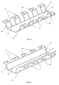
- FIG. 1 shows a schematic perspective view of a deformation element according to an embodiment of the invention
- FIG. 2 shows a schematic perspective view of a deformation element according to another embodiment of the invention
- FIG. 3 shows a schematic perspective view of a deformation element according to another embodiment of the invention
- FIG. 4 shows a schematic perspective view of a deformation element according to another embodiment of the invention
- FIG. 5 shows a schematic cross-sectional view of a deformation element according to the invention in the mounted state on a vehicle roof
- FIG. 6 shows a plan view of a vehicle sky with a plurality of deformation elements according to the invention.
- FIG. 1 an energy absorbing deformation element 1 according to an embodiment of the invention is shown.
- the deformation element 1 is arranged in the mounted state in an impact area between a trim part of a vehicle and a vehicle body.
- the deformation element 1 is in particular between a headliner 9 (cf., eg FIG. 5 ) and a vehicle roof 11 (see, eg FIG. 5 ) arranged. But it is also conceivable to arrange the deformation element 1 in vehicle pillars or the like.
- the deformation element 1 consists of a substantially U-shaped profile 2, at the free end regions in each case at least partially a flange 3, 4 is arranged.
- the substantially U-shaped profile 2 comprises two deformation walls 5, which are aligned in the assembled state substantially parallel to each other and which are connected to at least one bottom part 6 to form a one-piece component.
- the deformation element 1 is preferably made of sheet metal or a plastic material.
- the flanges 3, 4 project in each case laterally from the free ends of the deformation walls 5 of the U-shaped profile. Furthermore, the flanges can be angled relative to the deformation walls 5, that the flanges run konturbmony with the vehicle body.
- a plurality of recesses or notches 7 are provided in the flanges.
- the recesses or notches 7 are rectangular, as can be seen from the figures.
- the notches 7 extend to the walls 5 of the U-shaped profile 2.
- the number of notches 7 and the distance between adjacent notches 7 can be selected so that the desired deformation properties are achieved.
- the size of the notches 7 corresponds to the size of the flanges or tabs 8 remaining between them.
- the height of the deformation walls corresponds to the distance between the trim part (eg the headliner) and the vehicle body (eg the vehicle roof), so that in the installed state the flanges 3, 4 of the deformation element there in each case abut in a system connection.
- FIG. 2 an energy absorbing deformation element 1 according to another preferred embodiment of the invention is shown. Identical elements are given the same reference numerals.
- the notches or recesses 7 extend into the deformation walls 5 and preferably to the base or bottom part 6 of the U-shaped profile. In this case, the rigidity of the deformation element 1 is reduced.
- the notches or recesses 7 are provided in opposing flanges 3, 4 and deformation walls 5 and the notches or recesses 7 are directly opposite.
- the number of notches 7 and the distance between adjacent notches 7 can in turn be selected so that the desired deformation properties are achieved.
- the width of the notches 7 is equal to the width of the flanges or tabs 8 remaining between them.
- FIG. 3 shows a development of the deformation element 1 in FIG. 2 in which the notches or recesses 7 in opposite-lying flanges 3, 4 and deformation walls 5 are offset from one another in the longitudinal direction of the U-profile 2.
- FIG. 4 shows a development of the deformation element 1 in FIG. 1 in which the notches or recesses 7 in opposite flanges 3, 4 are offset from one another in the longitudinal direction of the U-profile 2.
- the arrangement of the deformation element 1 between a headliner 9 and a vehicle roof 11 of a vehicle is shown. It can be seen that the bottom of the bottom part 6 is connected to a rear side of the headliner 9. Preferably, the bottom of the bottom part 6 is glued to the back of the headliner 9. The profile of the bottom part 6 can continue to be designed so that it runs flush with the headliner 9.
- the two deformation walls 5 extend between the headliner 9 and the vehicle roof 11, and preferably the flanges 3, 4 respectively protrude from the free ends the deformation walls 5 of the U-shaped profile 2 laterally.
- the flanges 3, 4 can be angled relative to the deformation walls 5 in such a way that the flanges extend flush with the vehicle roof 11.
- the center line of the vehicle is designated by reference numeral 10 in the FIGS. 5 and 6 designated. It can be seen here that the deformation element 1 is arranged to the side of the vehicle and corresponds to the longitudinal direction of the deformation element in the mounted state of the longitudinal direction of the vehicle in order to achieve improved occupant protection. Several deformation elements 1 are provided in the longitudinal direction of the vehicle.
Landscapes
- Engineering & Computer Science (AREA)
- Mechanical Engineering (AREA)
- Body Structure For Vehicles (AREA)
Applications Claiming Priority (1)
| Application Number | Priority Date | Filing Date | Title |
|---|---|---|---|
| DE102007019700A DE102007019700A1 (de) | 2007-04-26 | 2007-04-26 | Energieabsorbierendes Deformationselement für ein Fahrzeug |
Publications (3)
| Publication Number | Publication Date |
|---|---|
| EP1985508A2 true EP1985508A2 (fr) | 2008-10-29 |
| EP1985508A3 EP1985508A3 (fr) | 2011-05-25 |
| EP1985508B1 EP1985508B1 (fr) | 2013-01-02 |
Family
ID=39535308
Family Applications (1)
| Application Number | Title | Priority Date | Filing Date |
|---|---|---|---|
| EP08001151A Not-in-force EP1985508B1 (fr) | 2007-04-26 | 2008-01-23 | Elément de déformation absorbant l'énergie pour un véhicule |
Country Status (4)
| Country | Link |
|---|---|
| US (1) | US7954883B2 (fr) |
| EP (1) | EP1985508B1 (fr) |
| CN (1) | CN101293504B (fr) |
| DE (1) | DE102007019700A1 (fr) |
Families Citing this family (12)
| Publication number | Priority date | Publication date | Assignee | Title |
|---|---|---|---|---|
| DE102008053769A1 (de) * | 2008-10-22 | 2010-04-29 | Dr.Ing.H.C.F.Porsche Aktiengesellschaft | Deformationselement zur Anpralldämpfung in einem Kraftfahrzeug |
| KR20110062425A (ko) * | 2009-12-03 | 2011-06-10 | 현대자동차주식회사 | 차량용 루프 레일 |
| US8348313B2 (en) | 2010-08-31 | 2013-01-08 | International Automotive Components Group North America, Inc. | Energy absorber for vehicle bumper |
| US8186748B2 (en) | 2010-08-31 | 2012-05-29 | International Automotive Components Group North America, Inc. | Energy absorber for vehicle overhead system |
| DE102012209498B4 (de) * | 2012-06-05 | 2024-10-02 | Bayerische Motoren Werke Aktiengesellschaft | Fahrzeugdach für einen Kraftwagen |
| DE102012024566A1 (de) | 2012-12-15 | 2013-08-01 | Daimler Ag | Dachmodul für ein Fahrzeugdach eines Personenkraftwagens |
| US20160052367A1 (en) * | 2014-08-25 | 2016-02-25 | GM Global Technology Operations LLC | Energy absorbing air handling device for a vehicle |
| JP6652033B2 (ja) * | 2016-11-02 | 2020-02-19 | トヨタ自動車株式会社 | 車体ルーフ構造 |
| JP6787170B2 (ja) * | 2017-02-20 | 2020-11-18 | トヨタ紡織株式会社 | 車両用衝撃吸収構造 |
| JP2018134936A (ja) * | 2017-02-21 | 2018-08-30 | 三菱自動車工業株式会社 | レーダー取付構造 |
| CN111148907B (zh) * | 2017-11-01 | 2022-06-24 | 日本制铁株式会社 | 重叠接合构造 |
| DE102017131325A1 (de) * | 2017-12-27 | 2019-06-27 | Borgward Trademark Holdings Gmbh | Armaturenbrettanordnung für ein Fahrzeug und Fahrzeug |
Citations (2)
| Publication number | Priority date | Publication date | Assignee | Title |
|---|---|---|---|---|
| DE10063339C1 (de) | 2000-12-19 | 2001-12-06 | Porsche Ag | Energieabsorbierendes Deformationselement |
| DE102004058249A1 (de) | 2004-12-03 | 2006-06-08 | Volkswagen Ag | Sicherheitseinrichtung für ein Fahrzeug, insbesondere für ein Kraftfahrzeug |
Family Cites Families (20)
| Publication number | Priority date | Publication date | Assignee | Title |
|---|---|---|---|---|
| DE3838595A1 (de) * | 1988-11-15 | 1990-05-17 | Kolbenschmidt Ag | Bauelement zur absorption von energie |
| JP3381456B2 (ja) * | 1995-05-23 | 2003-02-24 | 日産自動車株式会社 | 自動車用ピラーガーニッシュ支持構造 |
| JP3000898B2 (ja) * | 1995-07-12 | 2000-01-17 | トヨタ自動車株式会社 | 自動車の衝撃エネルギ吸収構造 |
| AU685706B2 (en) * | 1995-07-31 | 1998-01-22 | Toyota Jidosha Kabushiki Kaisha | Collision energy absorbing structure of vehicle body upper portion of automobile |
| US5564744A (en) * | 1995-08-30 | 1996-10-15 | Davidson Textron Inc. | Energy absorbent interior trim for vehicle |
| JP3362598B2 (ja) * | 1996-04-12 | 2003-01-07 | トヨタ自動車株式会社 | 自動車の車体上部のエネルギ吸収構造 |
| US6254172B1 (en) * | 1997-06-18 | 2001-07-03 | Toyota Jidosha Kabushiki Kaisha | Automotive impact energy absorbing structure |
| US5979139A (en) * | 1998-01-06 | 1999-11-09 | Aero Transportation Products, Inc. | Lightweight, self-supporting paneling |
| US6036227A (en) * | 1998-02-23 | 2000-03-14 | General Motors Corporation | Vehicle headliner with impact protection |
| US6041176A (en) * | 1998-02-27 | 2000-03-21 | Texas Instruments Incorporated | Emulation devices utilizing state machines |
| US6199941B1 (en) * | 1998-05-08 | 2001-03-13 | Toyota Jidosha Kabushiki Kaisha | Impact energy absorbing structure in upper vehicle body portion and impact energy absorbing member |
| JP3097684B2 (ja) * | 1999-01-14 | 2000-10-10 | トヨタ自動車株式会社 | 自動車の車体上部の衝撃エネルギ吸収構造 |
| JP2000289650A (ja) | 1999-04-06 | 2000-10-17 | Fuji Heavy Ind Ltd | 室内衝撃吸収構造 |
| JP3607982B2 (ja) * | 2000-05-17 | 2005-01-05 | トヨタ自動車株式会社 | 車体上方構造 |
| DE10101450A1 (de) | 2001-01-15 | 2002-07-25 | Arvinmeritor Gmbh | Fahrzeugdach, insbesondere Kraftfahrzeugdach |
| US6779835B2 (en) * | 2001-12-06 | 2004-08-24 | Lear Corporation | Energy absorbing structure for automobile interior |
| JP4144362B2 (ja) * | 2003-01-20 | 2008-09-03 | スズキ株式会社 | ブラケット取付構造 |
| DE102004026200A1 (de) * | 2004-05-28 | 2005-12-29 | Dr.Ing.H.C. F. Porsche Ag | Kraftfahrzeug mit einem Energie absorbierenden Deformationselement |
| JP4531468B2 (ja) * | 2004-07-14 | 2010-08-25 | 小島プレス工業株式会社 | 車両用衝撃吸収構造体及びその取付構造 |
| US7604286B2 (en) | 2006-01-13 | 2009-10-20 | Nissan Motor Co., Ltd. | Roof structure of a vehicular body |
-
2007
- 2007-04-26 DE DE102007019700A patent/DE102007019700A1/de not_active Withdrawn
-
2008
- 2008-01-23 EP EP08001151A patent/EP1985508B1/fr not_active Not-in-force
- 2008-02-26 US US12/037,467 patent/US7954883B2/en not_active Expired - Fee Related
- 2008-04-22 CN CN2008100945439A patent/CN101293504B/zh not_active Expired - Fee Related
Patent Citations (2)
| Publication number | Priority date | Publication date | Assignee | Title |
|---|---|---|---|---|
| DE10063339C1 (de) | 2000-12-19 | 2001-12-06 | Porsche Ag | Energieabsorbierendes Deformationselement |
| DE102004058249A1 (de) | 2004-12-03 | 2006-06-08 | Volkswagen Ag | Sicherheitseinrichtung für ein Fahrzeug, insbesondere für ein Kraftfahrzeug |
Also Published As
| Publication number | Publication date |
|---|---|
| EP1985508A3 (fr) | 2011-05-25 |
| US7954883B2 (en) | 2011-06-07 |
| US20080265622A1 (en) | 2008-10-30 |
| CN101293504A (zh) | 2008-10-29 |
| DE102007019700A1 (de) | 2008-10-30 |
| CN101293504B (zh) | 2013-01-02 |
| EP1985508B1 (fr) | 2013-01-02 |
Similar Documents
| Publication | Publication Date | Title |
|---|---|---|
| EP1985508B1 (fr) | Elément de déformation absorbant l'énergie pour un véhicule | |
| EP1036715B1 (fr) | Ensemble pare-chocs | |
| EP2014539B1 (fr) | Carrosserie de véhicule automobile dotée de longerons latéraux | |
| EP2018999B1 (fr) | Absorbeur d'énergie destiné à servir de protection contre les chocs dans un véhicule automobile | |
| DE102008023340A1 (de) | Aggregateträger für ein Getriebe eines Kraftfahrzeugs | |
| EP1954550B1 (fr) | Support de montage de structure hybride | |
| DE102007032245A1 (de) | Kraftfahrzeugkarosserie mit seitlichen Schwellern | |
| DE102007056673A1 (de) | Karosserieaufbau | |
| DE102018008894A1 (de) | Energieabsorptions-Baueinheit für einen Kraftwagen sowie Energieabsorptionselement und Verstärkungselement hierfür | |
| EP1923257B1 (fr) | Fixation pour un siège de véhicule automobile | |
| DE202009017309U1 (de) | Unterbodenverkleidung | |
| EP3484735A1 (fr) | Procédé de fabrication d'un toit de véhicule, toit modulaire pour toit de véhicule et toit de véhicule pour véhicule à moteur | |
| DE102012022899A1 (de) | Verbindungselement zur Abstützung eines Stoßfängers eines Kraftfahrzeuges gegenüber einem Montageträger, Baueinheit mit einem solchen Verbindungselement sowie Verfahren zur Herstellung eines Verbindungselements | |
| DE102021002367A1 (de) | Bodenstruktur für einen Personenkraftwagen | |
| DE102010014513A1 (de) | Verbindungsanordnung von wenigstens zwei Strukturbauteilen für einen Kraftwagen sowie Verfahren zu deren Herstellung | |
| DE102007032246B4 (de) | Kraftfahrzeugkarosserie mit seitlichen Schwellern | |
| DE102013002537A1 (de) | Schweller-Bodenstruktur-Anordnung | |
| DE102021102050A1 (de) | Batteriegehäuse, Kraftfahrzeug und Verfahren zum Bereitstellen eines Batteriegehäuses | |
| DE102011014454A1 (de) | Profilteil für einen Kraftwagen | |
| DE102011016100A1 (de) | Klappbare Rückenlehne eines Rücksitzes eines Kraftfahrzeuges | |
| DE102020202883A1 (de) | Unterbaustruktur für ein Fahrzeug | |
| DE102004016839B4 (de) | Vorrichtung zur Aufnahme von Stoßenergie | |
| DE102004058249B4 (de) | Sicherheitseinrichtung für ein Fahrzeug, insbesondere für ein Kraftfahrzeug | |
| DE102010054688A1 (de) | Bodenstruktur für ein Kraftfahrzeug, Fahrzeugkarosserie und Kraftfahrzeug | |
| DE102005016994A1 (de) | Kraftfahrzeug mit einem Versteifungselement |
Legal Events
| Date | Code | Title | Description |
|---|---|---|---|
| PUAI | Public reference made under article 153(3) epc to a published international application that has entered the european phase |
Free format text: ORIGINAL CODE: 0009012 |
|
| AK | Designated contracting states |
Kind code of ref document: A2 Designated state(s): AT BE BG CH CY CZ DE DK EE ES FI FR GB GR HR HU IE IS IT LI LT LU LV MC MT NL NO PL PT RO SE SI SK TR |
|
| AX | Request for extension of the european patent |
Extension state: AL BA MK RS |
|
| RAP1 | Party data changed (applicant data changed or rights of an application transferred) |
Owner name: DR. ING. H.C. F. PORSCHE AG |
|
| PUAL | Search report despatched |
Free format text: ORIGINAL CODE: 0009013 |
|
| AK | Designated contracting states |
Kind code of ref document: A3 Designated state(s): AT BE BG CH CY CZ DE DK EE ES FI FR GB GR HR HU IE IS IT LI LT LU LV MC MT NL NO PL PT RO SE SI SK TR |
|
| AX | Request for extension of the european patent |
Extension state: AL BA MK RS |
|
| 17P | Request for examination filed |
Effective date: 20111125 |
|
| AKX | Designation fees paid |
Designated state(s): AT DE FR GB IT |
|
| GRAP | Despatch of communication of intention to grant a patent |
Free format text: ORIGINAL CODE: EPIDOSNIGR1 |
|
| GRAS | Grant fee paid |
Free format text: ORIGINAL CODE: EPIDOSNIGR3 |
|
| GRAA | (expected) grant |
Free format text: ORIGINAL CODE: 0009210 |
|
| AK | Designated contracting states |
Kind code of ref document: B1 Designated state(s): AT DE FR GB IT |
|
| REG | Reference to a national code |
Ref country code: GB Ref legal event code: FG4D Free format text: NOT ENGLISH |
|
| REG | Reference to a national code |
Ref country code: AT Ref legal event code: REF Ref document number: 591412 Country of ref document: AT Kind code of ref document: T Effective date: 20130115 |
|
| REG | Reference to a national code |
Ref country code: DE Ref legal event code: R096 Ref document number: 502008008978 Country of ref document: DE Effective date: 20130228 |
|
| PLBE | No opposition filed within time limit |
Free format text: ORIGINAL CODE: 0009261 |
|
| STAA | Information on the status of an ep patent application or granted ep patent |
Free format text: STATUS: NO OPPOSITION FILED WITHIN TIME LIMIT |
|
| 26N | No opposition filed |
Effective date: 20131003 |
|
| PG25 | Lapsed in a contracting state [announced via postgrant information from national office to epo] |
Ref country code: IT Free format text: LAPSE BECAUSE OF FAILURE TO SUBMIT A TRANSLATION OF THE DESCRIPTION OR TO PAY THE FEE WITHIN THE PRESCRIBED TIME-LIMIT Effective date: 20130102 |
|
| REG | Reference to a national code |
Ref country code: DE Ref legal event code: R097 Ref document number: 502008008978 Country of ref document: DE Effective date: 20131003 |
|
| REG | Reference to a national code |
Ref country code: AT Ref legal event code: MM01 Ref document number: 591412 Country of ref document: AT Kind code of ref document: T Effective date: 20130123 |
|
| PG25 | Lapsed in a contracting state [announced via postgrant information from national office to epo] |
Ref country code: AT Free format text: LAPSE BECAUSE OF NON-PAYMENT OF DUE FEES Effective date: 20130123 |
|
| REG | Reference to a national code |
Ref country code: FR Ref legal event code: PLFP Year of fee payment: 9 |
|
| REG | Reference to a national code |
Ref country code: FR Ref legal event code: PLFP Year of fee payment: 10 |
|
| REG | Reference to a national code |
Ref country code: FR Ref legal event code: PLFP Year of fee payment: 11 |
|
| PGFP | Annual fee paid to national office [announced via postgrant information from national office to epo] |
Ref country code: GB Payment date: 20180119 Year of fee payment: 11 |
|
| PGFP | Annual fee paid to national office [announced via postgrant information from national office to epo] |
Ref country code: FR Payment date: 20180119 Year of fee payment: 11 |
|
| GBPC | Gb: european patent ceased through non-payment of renewal fee |
Effective date: 20190123 |
|
| PG25 | Lapsed in a contracting state [announced via postgrant information from national office to epo] |
Ref country code: FR Free format text: LAPSE BECAUSE OF NON-PAYMENT OF DUE FEES Effective date: 20190131 |
|
| PG25 | Lapsed in a contracting state [announced via postgrant information from national office to epo] |
Ref country code: GB Free format text: LAPSE BECAUSE OF NON-PAYMENT OF DUE FEES Effective date: 20190123 |
|
| PGFP | Annual fee paid to national office [announced via postgrant information from national office to epo] |
Ref country code: DE Payment date: 20220126 Year of fee payment: 15 |
|
| REG | Reference to a national code |
Ref country code: DE Ref legal event code: R119 Ref document number: 502008008978 Country of ref document: DE |
|
| PG25 | Lapsed in a contracting state [announced via postgrant information from national office to epo] |
Ref country code: DE Free format text: LAPSE BECAUSE OF NON-PAYMENT OF DUE FEES Effective date: 20230801 |