EP1985508A2 - Energy absorbing deformation element for a motor vehicle - Google Patents
Energy absorbing deformation element for a motor vehicle Download PDFInfo
- Publication number
- EP1985508A2 EP1985508A2 EP08001151A EP08001151A EP1985508A2 EP 1985508 A2 EP1985508 A2 EP 1985508A2 EP 08001151 A EP08001151 A EP 08001151A EP 08001151 A EP08001151 A EP 08001151A EP 1985508 A2 EP1985508 A2 EP 1985508A2
- Authority
- EP
- European Patent Office
- Prior art keywords
- deformation element
- deformation
- shaped profile
- walls
- flanges
- Prior art date
- Legal status (The legal status is an assumption and is not a legal conclusion. Google has not performed a legal analysis and makes no representation as to the accuracy of the status listed.)
- Granted
Links
Images


Classifications
-
- B—PERFORMING OPERATIONS; TRANSPORTING
- B60—VEHICLES IN GENERAL
- B60R—VEHICLES, VEHICLE FITTINGS, OR VEHICLE PARTS, NOT OTHERWISE PROVIDED FOR
- B60R21/00—Arrangements or fittings on vehicles for protecting or preventing injuries to occupants or pedestrians in case of accidents or other traffic risks
- B60R21/02—Occupant safety arrangements or fittings, e.g. crash pads
- B60R21/04—Padded linings for the vehicle interior ; Energy absorbing structures associated with padded or non-padded linings
- B60R2021/0442—Padded linings for the vehicle interior ; Energy absorbing structures associated with padded or non-padded linings associated with the roof panel
Definitions
- the invention relates to an energy-absorbing deformation element according to the preamble of claim 1.
- an energy absorbing deformation member which is arranged in a body structure between a shell member and an interior trim panel and consists of a lattice-like member.
- the deformation element consists of mutually spaced U-profiles with a web and between legs of the profiles arranged transversely stiffening webs.
- the profiles are connected via connecting webs to an elongate, at least arranged in a plane assembly.
- the production of the deformation element is complicated because of the various components.
- a deformation element which is formed by two spaced-apart deformation walls, which are aligned substantially parallel to each other and which are connected to at least one connecting part to a one-piece component. At a free end portion of the deformation walls, a flange is arranged.
- the production of the deformation element is simplified.
- the design of the deformation element does not always offer optimum occupant protection.
- the object of the invention is to provide a deformation element for a vehicle, in particular for a motor vehicle, which is simple to manufacture and offers improved occupant protection. This object is achieved by a deformation element with the features of claim 1. Advantageous developments of the deformation element according to the invention will become apparent from the dependent claims.
- the deformation element according to the invention consists of a substantially U-shaped profile, at the free end regions in each case at least partially a flange is arranged, wherein a plurality of notches or recesses are provided in the flange.
- the notches extend into the walls of the U-shaped profile to the bottom part of the U-shaped profile. With this configuration, the deformation element is easily deformed.
- the notches in opposite flanges are directly opposite each other. In this case, advantageous deformation properties of the deformation element are achieved.
- the notches are offset in opposing flanges in the longitudinal direction of the U-profile to each other. In this case, other advantageous deformation properties of the deformation element are achieved.
- FIG. 1 shows a schematic perspective view of a deformation element according to an embodiment of the invention
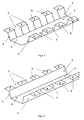
- FIG. 2 shows a schematic perspective view of a deformation element according to another embodiment of the invention
- FIG. 3 shows a schematic perspective view of a deformation element according to another embodiment of the invention
- FIG. 4 shows a schematic perspective view of a deformation element according to another embodiment of the invention
- FIG. 5 shows a schematic cross-sectional view of a deformation element according to the invention in the mounted state on a vehicle roof
- FIG. 6 shows a plan view of a vehicle sky with a plurality of deformation elements according to the invention.
- FIG. 1 an energy absorbing deformation element 1 according to an embodiment of the invention is shown.
- the deformation element 1 is arranged in the mounted state in an impact area between a trim part of a vehicle and a vehicle body.
- the deformation element 1 is in particular between a headliner 9 (cf., eg FIG. 5 ) and a vehicle roof 11 (see, eg FIG. 5 ) arranged. But it is also conceivable to arrange the deformation element 1 in vehicle pillars or the like.
- the deformation element 1 consists of a substantially U-shaped profile 2, at the free end regions in each case at least partially a flange 3, 4 is arranged.
- the substantially U-shaped profile 2 comprises two deformation walls 5, which are aligned in the assembled state substantially parallel to each other and which are connected to at least one bottom part 6 to form a one-piece component.
- the deformation element 1 is preferably made of sheet metal or a plastic material.
- the flanges 3, 4 project in each case laterally from the free ends of the deformation walls 5 of the U-shaped profile. Furthermore, the flanges can be angled relative to the deformation walls 5, that the flanges run konturbmony with the vehicle body.
- a plurality of recesses or notches 7 are provided in the flanges.
- the recesses or notches 7 are rectangular, as can be seen from the figures.
- the notches 7 extend to the walls 5 of the U-shaped profile 2.
- the number of notches 7 and the distance between adjacent notches 7 can be selected so that the desired deformation properties are achieved.
- the size of the notches 7 corresponds to the size of the flanges or tabs 8 remaining between them.
- the height of the deformation walls corresponds to the distance between the trim part (eg the headliner) and the vehicle body (eg the vehicle roof), so that in the installed state the flanges 3, 4 of the deformation element there in each case abut in a system connection.
- FIG. 2 an energy absorbing deformation element 1 according to another preferred embodiment of the invention is shown. Identical elements are given the same reference numerals.
- the notches or recesses 7 extend into the deformation walls 5 and preferably to the base or bottom part 6 of the U-shaped profile. In this case, the rigidity of the deformation element 1 is reduced.
- the notches or recesses 7 are provided in opposing flanges 3, 4 and deformation walls 5 and the notches or recesses 7 are directly opposite.
- the number of notches 7 and the distance between adjacent notches 7 can in turn be selected so that the desired deformation properties are achieved.
- the width of the notches 7 is equal to the width of the flanges or tabs 8 remaining between them.
- FIG. 3 shows a development of the deformation element 1 in FIG. 2 in which the notches or recesses 7 in opposite-lying flanges 3, 4 and deformation walls 5 are offset from one another in the longitudinal direction of the U-profile 2.
- FIG. 4 shows a development of the deformation element 1 in FIG. 1 in which the notches or recesses 7 in opposite flanges 3, 4 are offset from one another in the longitudinal direction of the U-profile 2.
- the arrangement of the deformation element 1 between a headliner 9 and a vehicle roof 11 of a vehicle is shown. It can be seen that the bottom of the bottom part 6 is connected to a rear side of the headliner 9. Preferably, the bottom of the bottom part 6 is glued to the back of the headliner 9. The profile of the bottom part 6 can continue to be designed so that it runs flush with the headliner 9.
- the two deformation walls 5 extend between the headliner 9 and the vehicle roof 11, and preferably the flanges 3, 4 respectively protrude from the free ends the deformation walls 5 of the U-shaped profile 2 laterally.
- the flanges 3, 4 can be angled relative to the deformation walls 5 in such a way that the flanges extend flush with the vehicle roof 11.
- the center line of the vehicle is designated by reference numeral 10 in the FIGS. 5 and 6 designated. It can be seen here that the deformation element 1 is arranged to the side of the vehicle and corresponds to the longitudinal direction of the deformation element in the mounted state of the longitudinal direction of the vehicle in order to achieve improved occupant protection. Several deformation elements 1 are provided in the longitudinal direction of the vehicle.
Landscapes
- Engineering & Computer Science (AREA)
- Mechanical Engineering (AREA)
- Body Structure For Vehicles (AREA)
Abstract
Die Erfindung betrifft ein Energieabsorbierendes Deformationselement für ein Fahrzeug, insbesondere für ein Kraftfahrzeug, bei dem das Deformationselement im montierten Zustand in einem Anprallbereich zwischen einem Verkleidungsteil und einer Fahrzeugkarosserie, insbesondere zwischen einem Dachhimmel und einem Fahrzeugdach angeordnet ist. Das Deformationselement besteht aus einem im Wesentlichen U-förmigen Profil, an dessen freien Endbereichen jeweils wenigstens bereichsweise ein Flansch angeordnet ist, wobei mehrere Ausklinkungen oder Ausnehmungen in den Flanschen vorgesehen sind.The invention relates to an energy absorbing deformation element for a vehicle, in particular for a motor vehicle, in which the deformation element is arranged in the mounted state in an impact region between a trim part and a vehicle body, in particular between a headliner and a vehicle roof. The deformation element consists of a substantially U-shaped profile, at the free end regions in each case at least partially a flange is arranged, wherein a plurality of notches or recesses are provided in the flanges.
Description
Die Erfindung bezieht sich auf ein energieabsorbierendes Deformationselement nach dem Oberbegriff des Anspruchs 1.The invention relates to an energy-absorbing deformation element according to the preamble of
Aus der
Aus der
Aufgabe der Erfindung ist es, ein Deformationselement für ein Fahrzeug, insbesondere für ein Kraftfahrzeug, zu schaffen, das einfach herzustellen ist und einen verbesserten Insassenschutz bietet.
Diese Aufgabe wird erfindungsgemäß durch ein Deformationselement mit den Merkmalen des Anspruchs 1 gelöst. Vorteilhafte Weiterbildungen des erfindungsgemäßen Deformationselements ergeben sich aus den abhängigen Ansprüchen.The object of the invention is to provide a deformation element for a vehicle, in particular for a motor vehicle, which is simple to manufacture and offers improved occupant protection.
This object is achieved by a deformation element with the features of
Das erfindungsgemäße Deformationselement besteht aus einem im Wesentlichen U-förmigen Profil, an dessen freien Endbereichen jeweils wenigstens bereichsweise ein Flansch angeordnet ist, wobei mehrere Ausklinkungen oder Ausnehmungen im Flansch vorgesehen sind. Diese Gestaltung ermöglicht auf einfache Weise ein Deformationselement herzustellen, das verbesserte Deformationseigenschaften besitzt und verbesserten Insassenschutz bietet.The deformation element according to the invention consists of a substantially U-shaped profile, at the free end regions in each case at least partially a flange is arranged, wherein a plurality of notches or recesses are provided in the flange. This design makes it possible to easily produce a deformation element that has improved deformation properties and offers improved occupant protection.
In vorteilhafter Weiterbildung erstrecken sich die Ausklinkungen in die Wände des U-förmigen Profils bis zum Bodenteil des U-förmigen Profils. Bei dieser Gestaltung wird das Deformationselement leicht deformiert.In an advantageous embodiment, the notches extend into the walls of the U-shaped profile to the bottom part of the U-shaped profile. With this configuration, the deformation element is easily deformed.
In einer weiteren vorteilhaften Weiterbildung liegen die Ausklinkungen in gegenüber angeordneten Flanschen einander direkt gegenüber. Hierbei werden vorteilhafte Deformationseigenschaften des Deformationselements erzielt.In a further advantageous development, the notches in opposite flanges are directly opposite each other. In this case, advantageous deformation properties of the deformation element are achieved.
In einer weiteren vorteilhaften Weiterbildung sind die Ausklinkungen in gegenüberliedenden Flanschen in Längsrichtung des U-Profils zueinander versetzt. Hierbei werden andere vorteilhafte Deformationseigenschaften des Deformationselements erzielt.In a further advantageous development, the notches are offset in opposing flanges in the longitudinal direction of the U-profile to each other. In this case, other advantageous deformation properties of the deformation element are achieved.
Weitere Vorteile und Ausgestaltungen der Erfindung ergeben sich aus der nachfolgenden Beschreibung und den beiliegenden Zeichnungen.Further advantages and embodiments of the invention will become apparent from the following description and the accompanying drawings.
Es versteht sich, dass die vorstehend genannten und die nachstehend noch zu erläuternden Merkmale nicht nur in der jeweils angegebenen Kombination, sondern auch in anderen Kombinationen oder in Alleinstellung verwendbar sind, ohne den Rahmen der vorliegenden Erfindung zu verlassen.It is understood that the features mentioned above and those yet to be explained below can be used not only in the particular combination given, but also in other combinations or in isolation, without departing from the scope of the present invention.
Die Erfindung ist anhand mehrerer Ausführungsbeispiele in den Zeichnungen schematisch dargestellt und wird im Folgenden unter Bezugnahme auf die Zeichnungen ausführlich beschrieben.The invention is illustrated schematically with reference to several embodiments in the drawings and will be described in detail below with reference to the drawings.
In
Das Deformationselement 1 besteht aus einem im Wesentlichen U-förmigen Profil 2, an dessen freien Endbereichen jeweils wenigstens bereichsweise ein Flansch 3, 4 angeordnet ist. Das im Wesentlichen U-förmige Profil 2 umfasst zwei Deformationswände 5, die im montierten Zustand im Wesentlichen parallel zueinander ausgerichtet sind und die mit wenigstens einem Bodenteil 6 zu einem einstückigen Bauteil verbunden sind. Das Deformationselement 1 ist vorzugsweise aus Blech oder einem Kunststoffmaterial gefertigt.The
Die Flansche 3, 4 ragen jeweils von den freien Enden der Deformationswände 5 des U-förmigen Profils vorzugsweise seitlich hinaus. Weiterhin können die Flansche so gegenüber den Deformationswände 5 abgewinkelt sind, dass die Flansche konturbündig mit der Fahrzeugkarosserie verlaufen.The
Erfindungsgemäß werden mehrere Ausnehmungen oder Ausklinkungen 7 in den Flanschen vorgesehen. Bei der Veränderung der Größe der Ausklinkungen oder der Ausnehmungen 7 können die Deformationseigenschaften auf einfache Weise angepasst werden. Vorzugsweise sind die Ausnehmungen oder Ausklinkungen 7 rechteckig ausgebildet, wie aus den Figuren ersichtlich ist. In der Ausführungsform in
In
Die
Die
In den
Die zwei Deformationswände 5 verlaufen zwischen dem Dachhimmel 9 und dem Fahrzeugdach 11 und vorzugsweise ragen die Flansche 3, 4 jeweils von den freien Enden der Deformationswände 5 des U-förmigen Profils 2 seitlich hinaus. Wie bereits erwähnt können die Flansche 3, 4 so gegenüber den Deformationswände 5 abgewinkelt sein, dass die Flansche konturbündig mit dem Fahrzeugdach 11 verlaufen.The two
Die Mittellinie des Fahrzeugs ist mit Bezugsziffer 10 in den
Die vorhergehende Beschreibung der Ausführungsbeispiele gemäß der vorliegenden Erfindung dient nur zu illustrativen Zwecken und nicht zum Zwecke der Beschränkung der Erfindung. Insbesondere im Hinblick auf einige bevorzugte Ausführungsbeispiele entnimmt ihr der Fachmann, dass verschiedene Änderungen und Modifikationen in Gestalt und Einzelheiten gemacht werden können, ohne von dem Gedanken und Umfang der Erfindung abzuweichen. Dementsprechend soll die Offenbarung der vorliegenden Erfindung nicht einschränkend sein. Stattdessen soll die Offenbarung der vorliegenden Erfindung den Umfang der Erfindung veranschaulichen, der in den nachfolgenden Ansprüchen dargelegt ist.The foregoing description of the embodiments according to the present invention is for illustrative purposes only, and not for the purpose of limiting the invention. With particular reference to some preferred embodiments, those skilled in the art will appreciate that various changes and modifications in form and detail may be made without departing from the spirit and scope of the invention. Accordingly, the disclosure of the present invention is not intended to be limiting. Instead, the disclosure of the present invention is intended to illustrate the scope of the invention, which is set forth in the following claims.
Claims (10)
Applications Claiming Priority (1)
| Application Number | Priority Date | Filing Date | Title |
|---|---|---|---|
| DE102007019700A DE102007019700A1 (en) | 2007-04-26 | 2007-04-26 | Energy absorbing deformation element for a vehicle |
Publications (3)
| Publication Number | Publication Date |
|---|---|
| EP1985508A2 true EP1985508A2 (en) | 2008-10-29 |
| EP1985508A3 EP1985508A3 (en) | 2011-05-25 |
| EP1985508B1 EP1985508B1 (en) | 2013-01-02 |
Family
ID=39535308
Family Applications (1)
| Application Number | Title | Priority Date | Filing Date |
|---|---|---|---|
| EP08001151A Not-in-force EP1985508B1 (en) | 2007-04-26 | 2008-01-23 | Energy absorbing deformation element for a motor vehicle |
Country Status (4)
| Country | Link |
|---|---|
| US (1) | US7954883B2 (en) |
| EP (1) | EP1985508B1 (en) |
| CN (1) | CN101293504B (en) |
| DE (1) | DE102007019700A1 (en) |
Families Citing this family (12)
| Publication number | Priority date | Publication date | Assignee | Title |
|---|---|---|---|---|
| DE102008053769A1 (en) * | 2008-10-22 | 2010-04-29 | Dr.Ing.H.C.F.Porsche Aktiengesellschaft | Deformation element for use between inner cladding part and body of motorvehicle, has plates sliding along body during deformation of element and including surface with friction co-efficient larger than friction co-efficient of metal |
| KR20110062425A (en) * | 2009-12-03 | 2011-06-10 | 현대자동차주식회사 | Car Roof Rails |
| US8348313B2 (en) | 2010-08-31 | 2013-01-08 | International Automotive Components Group North America, Inc. | Energy absorber for vehicle bumper |
| US8186748B2 (en) | 2010-08-31 | 2012-05-29 | International Automotive Components Group North America, Inc. | Energy absorber for vehicle overhead system |
| DE102012209498B4 (en) * | 2012-06-05 | 2024-10-02 | Bayerische Motoren Werke Aktiengesellschaft | vehicle roof for a motor vehicle |
| DE102012024566A1 (en) | 2012-12-15 | 2013-08-01 | Daimler Ag | Roof module for vehicle e.g. passenger car, has guide element that is provided in absorbing region provided with energy absorption element which is deformed during indirect crash of head of vehicle occupant |
| US20160052367A1 (en) * | 2014-08-25 | 2016-02-25 | GM Global Technology Operations LLC | Energy absorbing air handling device for a vehicle |
| JP6652033B2 (en) * | 2016-11-02 | 2020-02-19 | トヨタ自動車株式会社 | Body roof structure |
| JP6787170B2 (en) * | 2017-02-20 | 2020-11-18 | トヨタ紡織株式会社 | Shock absorption structure for vehicles |
| JP2018134936A (en) | 2017-02-21 | 2018-08-30 | 三菱自動車工業株式会社 | Radar installation structure |
| ES3039526T3 (en) * | 2017-11-01 | 2025-10-22 | Nippon Steel Corp | Overlapping bonded structure |
| DE102017131325A1 (en) * | 2017-12-27 | 2019-06-27 | Borgward Trademark Holdings Gmbh | Dashboard assembly for a vehicle and vehicle |
Citations (2)
| Publication number | Priority date | Publication date | Assignee | Title |
|---|---|---|---|---|
| DE10063339C1 (en) | 2000-12-19 | 2001-12-06 | Porsche Ag | Energy-absorbing deformation element for automobile body component assembled from U-shaped profiles coupled together to provide elongate component |
| DE102004058249A1 (en) | 2004-12-03 | 2006-06-08 | Volkswagen Ag | Safety device for motor vehicle, has deformation unit formed by plate shaped deformation walls that are dimensioned and designed such that resisting force of unit increases than reaction force till threshold value by impact in impact area |
Family Cites Families (20)
| Publication number | Priority date | Publication date | Assignee | Title |
|---|---|---|---|---|
| DE3838595A1 (en) * | 1988-11-15 | 1990-05-17 | Kolbenschmidt Ag | COMPONENT FOR ABSORPTION OF ENERGY |
| JP3381456B2 (en) * | 1995-05-23 | 2003-02-24 | 日産自動車株式会社 | Pillar garnish support structure for automobiles |
| JP3000898B2 (en) * | 1995-07-12 | 2000-01-17 | トヨタ自動車株式会社 | Impact energy absorbing structure of automobile |
| AU685706B2 (en) * | 1995-07-31 | 1998-01-22 | Toyota Jidosha Kabushiki Kaisha | Collision energy absorbing structure of vehicle body upper portion of automobile |
| US5564744A (en) * | 1995-08-30 | 1996-10-15 | Davidson Textron Inc. | Energy absorbent interior trim for vehicle |
| JP3362598B2 (en) * | 1996-04-12 | 2003-01-07 | トヨタ自動車株式会社 | Energy absorption structure on the upper part of the car body |
| US6254172B1 (en) * | 1997-06-18 | 2001-07-03 | Toyota Jidosha Kabushiki Kaisha | Automotive impact energy absorbing structure |
| US5979139A (en) * | 1998-01-06 | 1999-11-09 | Aero Transportation Products, Inc. | Lightweight, self-supporting paneling |
| US6036227A (en) * | 1998-02-23 | 2000-03-14 | General Motors Corporation | Vehicle headliner with impact protection |
| US6041176A (en) * | 1998-02-27 | 2000-03-21 | Texas Instruments Incorporated | Emulation devices utilizing state machines |
| US6199941B1 (en) * | 1998-05-08 | 2001-03-13 | Toyota Jidosha Kabushiki Kaisha | Impact energy absorbing structure in upper vehicle body portion and impact energy absorbing member |
| JP3097684B2 (en) * | 1999-01-14 | 2000-10-10 | トヨタ自動車株式会社 | Impact energy absorbing structure on top of car body |
| JP2000289650A (en) | 1999-04-06 | 2000-10-17 | Fuji Heavy Ind Ltd | Indoor shock absorption structure |
| JP3607982B2 (en) * | 2000-05-17 | 2005-01-05 | トヨタ自動車株式会社 | Car body upper structure |
| DE10101450A1 (en) | 2001-01-15 | 2002-07-25 | Arvinmeritor Gmbh | Vehicle roof, in particular motor vehicle roof |
| US6779835B2 (en) * | 2001-12-06 | 2004-08-24 | Lear Corporation | Energy absorbing structure for automobile interior |
| JP4144362B2 (en) * | 2003-01-20 | 2008-09-03 | スズキ株式会社 | Bracket mounting structure |
| DE102004026200A1 (en) * | 2004-05-28 | 2005-12-29 | Dr.Ing.H.C. F. Porsche Ag | Motor vehicle with an energy-absorbing deformation element |
| JP4531468B2 (en) * | 2004-07-14 | 2010-08-25 | 小島プレス工業株式会社 | Shock absorbing structure for vehicle and its mounting structure |
| US7604286B2 (en) | 2006-01-13 | 2009-10-20 | Nissan Motor Co., Ltd. | Roof structure of a vehicular body |
-
2007
- 2007-04-26 DE DE102007019700A patent/DE102007019700A1/en not_active Withdrawn
-
2008
- 2008-01-23 EP EP08001151A patent/EP1985508B1/en not_active Not-in-force
- 2008-02-26 US US12/037,467 patent/US7954883B2/en not_active Expired - Fee Related
- 2008-04-22 CN CN2008100945439A patent/CN101293504B/en not_active Expired - Fee Related
Patent Citations (2)
| Publication number | Priority date | Publication date | Assignee | Title |
|---|---|---|---|---|
| DE10063339C1 (en) | 2000-12-19 | 2001-12-06 | Porsche Ag | Energy-absorbing deformation element for automobile body component assembled from U-shaped profiles coupled together to provide elongate component |
| DE102004058249A1 (en) | 2004-12-03 | 2006-06-08 | Volkswagen Ag | Safety device for motor vehicle, has deformation unit formed by plate shaped deformation walls that are dimensioned and designed such that resisting force of unit increases than reaction force till threshold value by impact in impact area |
Also Published As
| Publication number | Publication date |
|---|---|
| EP1985508B1 (en) | 2013-01-02 |
| US7954883B2 (en) | 2011-06-07 |
| EP1985508A3 (en) | 2011-05-25 |
| CN101293504A (en) | 2008-10-29 |
| CN101293504B (en) | 2013-01-02 |
| DE102007019700A1 (en) | 2008-10-30 |
| US20080265622A1 (en) | 2008-10-30 |
Similar Documents
| Publication | Publication Date | Title |
|---|---|---|
| EP1985508B1 (en) | Energy absorbing deformation element for a motor vehicle | |
| EP1036715B1 (en) | Bumper arrangement | |
| EP1954550B1 (en) | Hybrid-structure assembly support | |
| DE102008023340A1 (en) | Aggregate carrier for a transmission of a motor vehicle | |
| DE102007032244A1 (en) | Motor vehicle body with side sills | |
| DE102007032245A1 (en) | Motor vehicle body, has reinforcement part including U-shaped profile, and impact element provided between sheet metal outer part and reinforcement part for transmission of lateral impact forces, and partitioning element | |
| DE102007056673A1 (en) | body structure | |
| EP2018999A2 (en) | Energy absorber for use as collision protection in a motor vehicle | |
| DE102018008894A1 (en) | Energy absorption unit for a motor vehicle and energy absorption element and reinforcing element therefor | |
| EP1923257B1 (en) | Seat attachment for a motor vehicle seat | |
| DE202009017309U1 (en) | Underbody paneling | |
| EP2374666A2 (en) | Connection assembly with at least two structural components for a motor vehicle and method for producing same | |
| DE102008060715A1 (en) | Crash box for motor vehicle i.e. passenger car, has fastening units extending as integral component of extruded section in extruding directions, which run transverse and perpendicular to vehicle longitudinal direction | |
| DE102007032246B4 (en) | Motor vehicle body with side sills | |
| DE102021102050A1 (en) | Battery case, motor vehicle and method for providing a battery case | |
| DE102013002537A1 (en) | Ground sill structure arrangement of motor vehicle, has reinforcement structure that is arranged in floor structure and aligned transverse to vehicle longitudinal axis, same as energy-absorbing module | |
| DE102012009306A1 (en) | Bumper assembly for use in vehicle, particularly in tail end of vehicle, has cross beam made of foam, where base body of cross beam has transverse extending deformation structure, particularly support flange between connecting points | |
| DE102011016100A1 (en) | Folding backrest of a rear seat of a motor vehicle | |
| DE102020202883A1 (en) | Substructure for a vehicle | |
| DE102004016839B4 (en) | Device for absorbing impact energy | |
| DE102021002367B4 (en) | Floor structure for a passenger car | |
| DE102004058249B4 (en) | Safety device for a vehicle, in particular for a motor vehicle | |
| DE102011014454A1 (en) | Profile part for motor vehicle, has walls that form two closed chambers in partial manner, where solid foam is arranged in one of chambers | |
| DE102010054688A1 (en) | Floor structure for forming floor of car body of motor vehicle, has reinforcing structure for strengthening vehicle body, particularly in area of seat attachment | |
| DE102005016994A1 (en) | Method for reinforcing vehicle floor especially for cabriolet using a reinforcing panel with pressed profiles |
Legal Events
| Date | Code | Title | Description |
|---|---|---|---|
| PUAI | Public reference made under article 153(3) epc to a published international application that has entered the european phase |
Free format text: ORIGINAL CODE: 0009012 |
|
| AK | Designated contracting states |
Kind code of ref document: A2 Designated state(s): AT BE BG CH CY CZ DE DK EE ES FI FR GB GR HR HU IE IS IT LI LT LU LV MC MT NL NO PL PT RO SE SI SK TR |
|
| AX | Request for extension of the european patent |
Extension state: AL BA MK RS |
|
| RAP1 | Party data changed (applicant data changed or rights of an application transferred) |
Owner name: DR. ING. H.C. F. PORSCHE AG |
|
| PUAL | Search report despatched |
Free format text: ORIGINAL CODE: 0009013 |
|
| AK | Designated contracting states |
Kind code of ref document: A3 Designated state(s): AT BE BG CH CY CZ DE DK EE ES FI FR GB GR HR HU IE IS IT LI LT LU LV MC MT NL NO PL PT RO SE SI SK TR |
|
| AX | Request for extension of the european patent |
Extension state: AL BA MK RS |
|
| 17P | Request for examination filed |
Effective date: 20111125 |
|
| AKX | Designation fees paid |
Designated state(s): AT DE FR GB IT |
|
| GRAP | Despatch of communication of intention to grant a patent |
Free format text: ORIGINAL CODE: EPIDOSNIGR1 |
|
| GRAS | Grant fee paid |
Free format text: ORIGINAL CODE: EPIDOSNIGR3 |
|
| GRAA | (expected) grant |
Free format text: ORIGINAL CODE: 0009210 |
|
| AK | Designated contracting states |
Kind code of ref document: B1 Designated state(s): AT DE FR GB IT |
|
| REG | Reference to a national code |
Ref country code: GB Ref legal event code: FG4D Free format text: NOT ENGLISH |
|
| REG | Reference to a national code |
Ref country code: AT Ref legal event code: REF Ref document number: 591412 Country of ref document: AT Kind code of ref document: T Effective date: 20130115 |
|
| REG | Reference to a national code |
Ref country code: DE Ref legal event code: R096 Ref document number: 502008008978 Country of ref document: DE Effective date: 20130228 |
|
| PLBE | No opposition filed within time limit |
Free format text: ORIGINAL CODE: 0009261 |
|
| STAA | Information on the status of an ep patent application or granted ep patent |
Free format text: STATUS: NO OPPOSITION FILED WITHIN TIME LIMIT |
|
| 26N | No opposition filed |
Effective date: 20131003 |
|
| PG25 | Lapsed in a contracting state [announced via postgrant information from national office to epo] |
Ref country code: IT Free format text: LAPSE BECAUSE OF FAILURE TO SUBMIT A TRANSLATION OF THE DESCRIPTION OR TO PAY THE FEE WITHIN THE PRESCRIBED TIME-LIMIT Effective date: 20130102 |
|
| REG | Reference to a national code |
Ref country code: DE Ref legal event code: R097 Ref document number: 502008008978 Country of ref document: DE Effective date: 20131003 |
|
| REG | Reference to a national code |
Ref country code: AT Ref legal event code: MM01 Ref document number: 591412 Country of ref document: AT Kind code of ref document: T Effective date: 20130123 |
|
| PG25 | Lapsed in a contracting state [announced via postgrant information from national office to epo] |
Ref country code: AT Free format text: LAPSE BECAUSE OF NON-PAYMENT OF DUE FEES Effective date: 20130123 |
|
| REG | Reference to a national code |
Ref country code: FR Ref legal event code: PLFP Year of fee payment: 9 |
|
| REG | Reference to a national code |
Ref country code: FR Ref legal event code: PLFP Year of fee payment: 10 |
|
| REG | Reference to a national code |
Ref country code: FR Ref legal event code: PLFP Year of fee payment: 11 |
|
| PGFP | Annual fee paid to national office [announced via postgrant information from national office to epo] |
Ref country code: GB Payment date: 20180119 Year of fee payment: 11 |
|
| PGFP | Annual fee paid to national office [announced via postgrant information from national office to epo] |
Ref country code: FR Payment date: 20180119 Year of fee payment: 11 |
|
| GBPC | Gb: european patent ceased through non-payment of renewal fee |
Effective date: 20190123 |
|
| PG25 | Lapsed in a contracting state [announced via postgrant information from national office to epo] |
Ref country code: FR Free format text: LAPSE BECAUSE OF NON-PAYMENT OF DUE FEES Effective date: 20190131 |
|
| PG25 | Lapsed in a contracting state [announced via postgrant information from national office to epo] |
Ref country code: GB Free format text: LAPSE BECAUSE OF NON-PAYMENT OF DUE FEES Effective date: 20190123 |
|
| PGFP | Annual fee paid to national office [announced via postgrant information from national office to epo] |
Ref country code: DE Payment date: 20220126 Year of fee payment: 15 |
|
| REG | Reference to a national code |
Ref country code: DE Ref legal event code: R119 Ref document number: 502008008978 Country of ref document: DE |
|
| PG25 | Lapsed in a contracting state [announced via postgrant information from national office to epo] |
Ref country code: DE Free format text: LAPSE BECAUSE OF NON-PAYMENT OF DUE FEES Effective date: 20230801 |